EP4046899A1 - Roller, in particular electric roller - Google Patents
Roller, in particular electric roller Download PDFInfo
- Publication number
- EP4046899A1 EP4046899A1 EP21158693.8A EP21158693A EP4046899A1 EP 4046899 A1 EP4046899 A1 EP 4046899A1 EP 21158693 A EP21158693 A EP 21158693A EP 4046899 A1 EP4046899 A1 EP 4046899A1
- Authority
- EP
- European Patent Office
- Prior art keywords
- spring
- standpipe
- rear wheel
- scooter according
- swing arm
- Prior art date
- Legal status (The legal status is an assumption and is not a legal conclusion. Google has not performed a legal analysis and makes no representation as to the accuracy of the status listed.)
- Granted
Links
Images
Classifications
-
- B—PERFORMING OPERATIONS; TRANSPORTING
- B62—LAND VEHICLES FOR TRAVELLING OTHERWISE THAN ON RAILS
- B62K—CYCLES; CYCLE FRAMES; CYCLE STEERING DEVICES; RIDER-OPERATED TERMINAL CONTROLS SPECIALLY ADAPTED FOR CYCLES; CYCLE AXLE SUSPENSIONS; CYCLE SIDECARS, FORECARS, OR THE LIKE
- B62K3/00—Bicycles
- B62K3/002—Bicycles without a seat, i.e. the rider operating the vehicle in a standing position, e.g. non-motorized scooters; non-motorized scooters with skis or runners
-
- B—PERFORMING OPERATIONS; TRANSPORTING
- B62—LAND VEHICLES FOR TRAVELLING OTHERWISE THAN ON RAILS
- B62K—CYCLES; CYCLE FRAMES; CYCLE STEERING DEVICES; RIDER-OPERATED TERMINAL CONTROLS SPECIALLY ADAPTED FOR CYCLES; CYCLE AXLE SUSPENSIONS; CYCLE SIDECARS, FORECARS, OR THE LIKE
- B62K15/00—Collapsible or foldable cycles
- B62K15/006—Collapsible or foldable cycles the frame being foldable
-
- B—PERFORMING OPERATIONS; TRANSPORTING
- B62—LAND VEHICLES FOR TRAVELLING OTHERWISE THAN ON RAILS
- B62K—CYCLES; CYCLE FRAMES; CYCLE STEERING DEVICES; RIDER-OPERATED TERMINAL CONTROLS SPECIALLY ADAPTED FOR CYCLES; CYCLE AXLE SUSPENSIONS; CYCLE SIDECARS, FORECARS, OR THE LIKE
- B62K25/00—Axle suspensions
- B62K25/04—Axle suspensions for mounting axles resiliently on cycle frame or fork
- B62K25/28—Axle suspensions for mounting axles resiliently on cycle frame or fork with pivoted chain-stay
- B62K25/286—Axle suspensions for mounting axles resiliently on cycle frame or fork with pivoted chain-stay the shock absorber being connected to the chain-stay via a linkage mechanism
-
- B—PERFORMING OPERATIONS; TRANSPORTING
- B62—LAND VEHICLES FOR TRAVELLING OTHERWISE THAN ON RAILS
- B62K—CYCLES; CYCLE FRAMES; CYCLE STEERING DEVICES; RIDER-OPERATED TERMINAL CONTROLS SPECIALLY ADAPTED FOR CYCLES; CYCLE AXLE SUSPENSIONS; CYCLE SIDECARS, FORECARS, OR THE LIKE
- B62K2202/00—Motorised scooters
Definitions
- the invention relates to a scooter, in particular an electric scooter according to the preamble of patent claim 1.
- Scooters with an electric drive also known as e-scooters
- These vehicles have a compact design and can be stowed away in a space-saving manner thanks to the possibility of folding down the longitudinal column.
- the advantages of these electrically powered vehicles compared to motor vehicles are clearly visible in urban areas. They are environmentally friendly and require little energy due to their low weight. In addition, their required footprint is many times smaller and they are easy to handle because they can be folded up.
- Scooters of the type mentioned above are for example in the EP 2 425 989 A1 described.
- the handlebars of an electric scooter which are connected to the front wheel, and also its rear rocker with a suspension.
- two compression springs are arranged on both sides of the handlebar, or one compression spring is arranged surrounding the lower area of the handlebar facing the front wheel.
- one or two shock absorbers are also arranged on the outside between the wheel and the handlebars in order to counteract overshooting of the electric scooter. Individual springs and shock absorbers are also arranged in the area of the rear swing arm.
- - electric scooters are characterized in particular by the fact that they are space-saving and handy - springs and shock absorbers are insufficiently dimensioned due to the small available space, especially in the area of the rear swing arm, to cushion any shocks sufficiently comfortably.
- the invention has for its object to provide a scooter, in particular an electric scooter Rear swing arm has a comfortable suspension with damping and is designed to be compact. According to the invention, this object is achieved by a scooter having the features of the characterizing part of patent claim 1.
- a scooter in particular an electric scooter, is provided whose rear rocker has comfortable suspension with damping and which is of compact design.
- the at least one suspension system is formed by a compression spring, with the at least one compression spring and the at least one shock absorber being arranged on or in the tread element in the longitudinal direction of the latter, the compression spring and shock absorber can be well dimensioned without affecting the pack size of the scooter .
- At least one standpipe is attached to the tread element, in which a compression spring is positioned preloaded between a first displaceable spring mount and a second, stationary spring mount, the first spring mount being connected to a push rod protruding from the standpipe, which is connected to the Rear swing arm is connected.
- the compression spring is preferably designed as a helical spring.
- the push rod is guided through the second spring seat, which preferably has a cup-shaped spring cage in which the compression spring is arranged. This enables a compact arrangement.
- the second spring retainer has an external thread which engages with an internal thread of the standpipe and projects out of the respective standpipe in some areas, whereby the axial position of the second spring retainer within the standpipe can be adjusted.
- the spring tension of the compression spring can be adjusted.
- stationary spring mount is a condition to understand in operation. The second spring retainer is consequently stationary insofar as its position is not being changed to adjust the spring preload. Consequently, different, fixed positions of the second spring mount are possible.
- that part of the second spring receptacle which protrudes from the respective standpipe has a tool engagement which preferably comprises radially introduced bores. This makes it easier to adjust the preload of the compression spring by axially adjusting the second spring mount.
- the second spring seat is provided with a scale on which the respectively set spring preload can be read.
- a shock absorber is arranged in the at least one standpipe, which comprises a cylinder fixed in the standpipe with a piston that can be displaced therein, the piston rod of which is connected to the first spring receptacle.
- the at least one standpipe is formed from a first partial pipe on the spring side and a second partial pipe on the damper side, which two partial pipes are detachably connected to one another via a connecting piece.
- the two partial pipes are preferably screwed to the connecting piece.
- the connecting piece is preferably provided with an external thread at each of its two ends, onto which a partial pipe with an internal thread arranged for this purpose is screwed.
- the connecting piece is designed as a hub in which a connecting cylinder is slidably mounted, via which the piston rod of the shock absorber is connected to the first spring mount.
- the connecting rod, the first spring seat and the connecting cylinder of a standpipe are each formed by sections of a single shaft. This increases the stability of this arrangement.
- the piston rod can have an external thread at the end, with which it is screwed into an internally threaded bore of the connecting cylinder.
- the first spring seat is formed by a cylindrical shoulder, the outer diameter of which essentially corresponds to the inner diameter of the standpipe and which rests against a stop position on the connecting piece or a sealing element lying against it. This achieves a defined, guided movement of the first spring mount.
- the first spring seat is preferably designed in the form of a section with a larger diameter than the connecting cylinder.
- the rear wheel swing arm has two legs arranged opposite one another, with one of the standpipes being arranged on each of the two longitudinal sides of the step element, with one leg of the rear wheel swing arm being connected via a toggle lever to the push rod protruding from a standpipe.
- the two toggle levers are each formed from two levers that are pivotably connected to one another, the first lever being pivotably connected to the rear wheel swing arm and the second lever being pivotably connected to the connecting rod, and the second lever being pivotable about an axis fastened to the tread element is. Due to the ratio of the lengths of the two levers of the toggle levers, a defined conversion of the tilting movement of the rear wheel swing arm into the translatory movement of the two connecting rods is achieved.
- the second lever of the two toggle levers are preferably about a common axis fastened to the tread element pivoted, through which they are connected.
- the second lever of each toggle lever is pivotably connected to a connecting piece which has an internal thread with which it is screwed onto an external thread present at the end of the connecting rod.
- the second spring seat protrudes from the respective standpipe in some areas and has a section with an enlarged inner diameter at its end outside the standpipe, which delimits an annular gap with the connecting rod, in which the connecting piece engages in a stop position.
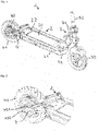
- the electric scooter 1 selected as an exemplary embodiment comprises a step element 2, which is connected in a known manner via a lockable pivoting device 3 to a frame strut 31 in which a steering rod 32 is rotatably mounted, which is provided on one side with a front wheel 33 and on the opposite side with a handlebar (not shown). .
- the steering rod 32 can be pivoted via the lockable pivoting device 3 into a position that is essentially parallel to the stepping element 2 .
- the tread element 2 is connected to a rear wheel 41 at the rear via a rear wheel swing arm 4 .
- the rear wheel 41 is connected to an electric motor 42 which is fed via an accumulator 20 which is accommodated by the tread element 2 .
- the tread element 2 comprises two side profiles 21 which are connected to one another at their ends via a transverse profile 22 arranged between them.
- the side profiles 21 and the transverse profiles 22 are designed as hollow profiles with a substantially rectangular cross section.
- the rectangular frame formed by the side profiles 21 and the transverse profiles 22 is provided on its underside with a floor, not shown, on which the accumulator 20 is arranged. On its upper side, the frame is closed by a cover--not shown.
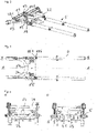
- the rear wheel swing arm 4 is essentially U-shaped and has two legs 43 arranged opposite one another, which end in an axle mount 432 for the rear wheel 41 .
- the rear wheel swing arm 4 has, on its side facing away from the legs 43, a stop part 44 with two spaced bushings 441, which are arranged on both sides of a bushing 23 present in the rear-side transverse profile 22 of the tread element 2, with which they can be connected via an axis guided through it 24 form a hinge via which the rear wheel swing arm 4 is pivotably connected to the transverse profile 22 of the tread element 2 .
- a standpipe 5 is accommodated in each case by the side profiles 21 of the step element 2 , which is formed from a first partial pipe 51 and a second partial pipe 52 , which partial pipes 51 , 52 are connected via a connecting piece 53 .
- the partial pipes 51, 52 each have an internal thread at the end, with which you can each connect to an end on the connecting piece 53 External threads are screwed on.
- the connecting piece 53 has a smaller inner diameter than the partial tubes 51, 52, as a result of which stops 54 are formed in the standpipe 5.
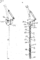
- a shaft 6 is arranged, which is subdivided into three functional sections.
- a connecting cylinder 61 is formed by a first cylindrical section, which is adjoined by a second, diameter-enlarged section, which forms the first spring receptacle 62 .
- the first spring seat 62 merges into a third, diameter-reduced cylindrical section, which forms the push rod 63, on the end of which a threaded pin 64 is formed.
- the shaft 6 is slidably mounted with the connecting cylinder 61 in the connecting piece 53 designed as a hub, the first spring receptacle 62 resting against a stop 54 of the connecting piece 53 in a position in a stop position.
- the stops 54 are provided with a damping layer, which is formed from a thermoelastic plastic in the exemplary embodiment.
- a helical spring 65 which rests against the first spring receptacle 62 and a second spring receptacle 55 which rests against the helical spring 65 are pushed onto the push rod 63 .
- the second spring receptacle 55 is sleeve-shaped and has a spring cage 551 at the end, by which the helical spring 65 is accommodated.
- an external thread is introduced into the second spring receptacle 55 , with which it is screwed into an internal thread arranged at the end in the first partial tube 51 .
- the external thread is followed by a circumferential indentation, with which the second spring receptacle 55 penetrates a locking ring 56 which is attached to the end of the first partial tube 51 .
- the locking ring 56 is composed of two ring halves in the exemplary embodiment.
- the second spring receptacle 55 is provided with a tool engagement 552, which is formed by circumferentially arranged radial blind bores.
- An inside diameter enlarged section is arranged inside in the area of the tool engagement 552, which together with the the push rod 63 guided by the second spring receptacle 55 delimits an annular gap 57 .
- the prestressing of the helical spring 65 can be adjusted by rotating the second spring receptacle 55 .
- a scale 553 is introduced on the outside of the second spring receptacle 55 in front of the tool engagement 552, on which scale the respectively set spring preload can be read.
- a shock absorber 7 is introduced into the second partial tube 52 of the standpipe 5 , the cylinder 71 of which is fastened via a screw which is guided through a plug 58 closing the second partial tube 52 at the end.
- a piston 72 is slidably guided in the cylinder 71 of the shock absorber 7, the piston rod 73 of which is screwed with its external thread at the end into a threaded blind bore made at the free end of the connecting cylinder 61 of the shaft 6, as a result of which the piston rod 73 is connected to the shaft 6.
- a snap ring 611 is fastened on the outside of the connecting cylinder 61, which in a stop position of the connecting cylinder 61 bears against the stop 54 of the connecting piece 53 facing it.
- the axial movement of the connecting cylinder 61 in the connecting piece 53 designed as a hub is thus limited on the one hand by the first spring mount 61 and on the other hand by the snap ring 611 .
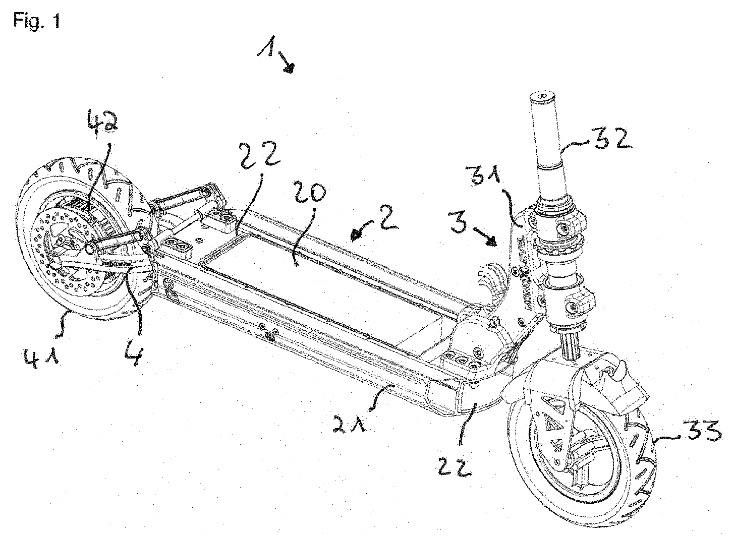
- the two toggle levers 8 are each formed by two levers 81, 82 which are pivotably connected to one another.
- the first, longer lever 81 is pivotally connected at its first end to a U-shaped bracket 431 arranged on the respective arm 43 of the rear wheel swing arm 4, in which it engages and is connected to it via an axle bolt 83.
- the second end of the first lever 81 is in turn connected to the second, shorter lever 82 via an axle bolt 83 .
- the second lever 82 has a slot-shaped recess 821 in which the first lever 81 engages.
- the second lever 82 of the two toggle levers 8 are provided with a passage through which one end of a common axle shaft 84 is guided and through which the two toggle levers 8 are connected to one another.
- the axle shaft 84 is rotatably mounted in two spaced-apart bushings 24 fastened on the rear-side transverse profile 22 .
- a connecting piece 85 is pivotably attached, which has a screw sleeve 851 which is screwed onto the threaded pin 64 of the shaft 6 of the associated standpipe 5.
- the screw sleeve 851 is accommodated in a stop position by the annular gap 57 delimited between the section of the second spring receptacle 55 with the enlarged inner diameter and the push rod 63 guided through it.
Landscapes
- Engineering & Computer Science (AREA)
- Mechanical Engineering (AREA)
- Axle Suspensions And Sidecars For Cycles (AREA)
Abstract
Die Erfindung betrifft einen Roller, insbesondere einen Elektroroller (1), mit einem Trittelement (2), das heckseitig schwenkbar mit einer Hinterradschwinge (4) zur Aufnahme eines Hinterrades (41) verbunden ist, wobei das Trittelement (2) und die Hinterradschwinge (4) zur Abfederung von Stößen mit wenigstens einer Federung und wenigstens einem Stoßdämpfer (7) verbunden sind. Die wenigstens eine Federung ist durch eine Druckfeder (65) gebildet, wobei die wenigstens eine Druckfeder (65) und der wenigstens eine Stoßdämpfer (7) in Längsrichtung des Trittelements (2) an diesem oder in diesem angeordnet sind.
Description
Die Erfindung betrifft einen Roller, insbesondere einen Elektroroller nach dem Oberbegriff des Patentanspruchs 1.The invention relates to a scooter, in particular an electric scooter according to the preamble of patent claim 1.
Mit einem Elektroantrieb versehene Roller, auch als E-Scooter bezeichnet, erfreuen sich zunehmender Beliebtheit. Diese Fahrzeuge sind kompakt ausgestaltet und durch die Möglichkeit des Umlegens der Längssäule platzsparend verstaubar. Die Vorteile dieser elektrisch angetriebenen Fahrzeuge gegenüber Kraftfahrzeugen sind im stadtnahen Bereich deutlich erkennbar. Sie sind umweltfreundlich und benötigen aufgrund ihres geringen Eigengewichtes wenig Energie. Außerdem ist ihre benötigte Stellfläche um ein Vielfaches kleiner und sie sind aufgrund ihrer Zusammenfaltbarkeit einfach zu handhaben. Roller der vorgenannten Art sind beispielsweise in der
Um auch auf holprigen Wegen ein komfortables Fahren zu ermöglichen, ist es bekannt, die mit dem Vorderrad verbundene Lenkstange eines Elektrorollers sowie auch seine Heckschwinge mit einer Federung zu versehen. Hierzu sind beispielsweise zwei Druckfedern beidseitig des Lenkers angeordnet, oder es ist eine Druckfeder dem unteren, dem Vorderrad zugewandten Bereich des Lenkers umgebend angeordnet. Weiterhin ist bekannt, außen zwischen Rad und Lenker einen, oder auch zwei Stoßdämpfer anzuordnen, um einem Überschwingen des Elektrorollers entgegenzuwirken. Im Bereich der Heckschwinge werden vereinzelnd ebenfalls Federn und Stoßdämpfer angeordnet.In order to enable comfortable driving even on bumpy roads, it is known to provide the handlebars of an electric scooter, which are connected to the front wheel, and also its rear rocker with a suspension. For this purpose, for example, two compression springs are arranged on both sides of the handlebar, or one compression spring is arranged surrounding the lower area of the handlebar facing the front wheel. It is also known to arrange one or two shock absorbers on the outside between the wheel and the handlebars in order to counteract overshooting of the electric scooter. Individual springs and shock absorbers are also arranged in the area of the rear swing arm.
Um das Packmaß möglichst gering zu halten - Elektroroller zeichnen sich insbesondere dadurch aus, dass sie platzsparend und handlich ausgebildet sind - sind Federn und Stoßdämpfer aufgrund des geringen verfügbaren Bauraums jedoch insbesondere im Bereich der Heckschwinge unzureichend dimensioniert, um auftretende Stöße hinreichend komfortabel abzufedern.In order to keep the pack size as small as possible - electric scooters are characterized in particular by the fact that they are space-saving and handy - springs and shock absorbers are insufficiently dimensioned due to the small available space, especially in the area of the rear swing arm, to cushion any shocks sufficiently comfortably.
Hier setzt die vorliegende Erfindung an. Der Erfindung liegt die Aufgabe zugrunde, einen Roller, insbesondere einen Elektroroller bereitzustellen, dessen Heckschwinge eine komfortable Federung mit Dämpfung aufweist und der dabei kompakt ausgebildet ist. Gemäß der Erfindung wird diese Aufgabe durch einen Roller mit den Merkmalen des kennzeichnenden Teils des Patentanspruchs 1 gelöst.This is where the present invention comes in. The invention has for its object to provide a scooter, in particular an electric scooter Rear swing arm has a comfortable suspension with damping and is designed to be compact. According to the invention, this object is achieved by a scooter having the features of the characterizing part of patent claim 1.
Mit der Erfindung ist ein Roller, insbesondere ein Elektroroller bereitgestellt, dessen Heckschwinge eine komfortable Federung mit Dämpfung aufweist und der dabei kompakt ausgebildet ist. Dadurch, dass die wenigstens eine Federung durch eine Druckfeder gebildet ist, wobei die wenigstens eine Druckfeder und der wenigstens eine Stoßdämpfer in Längsrichtung des Trittelements an diesem oder in diesem angeordnet sind, ist eine gute Dimensionierung von Druckfeder und Stoßdämpfer ohne Beeinträchtigung des Packmaßes des Rollers ermöglicht.With the invention, a scooter, in particular an electric scooter, is provided whose rear rocker has comfortable suspension with damping and which is of compact design. Because the at least one suspension system is formed by a compression spring, with the at least one compression spring and the at least one shock absorber being arranged on or in the tread element in the longitudinal direction of the latter, the compression spring and shock absorber can be well dimensioned without affecting the pack size of the scooter .
In Weiterbildung der Erfindung ist an dem Trittelement wenigstens ein Standrohr befestigt, in dem jeweils eine Druckfeder zwischen einer ersten verschiebbaren Federaufnahme und einer zweiten, ortsfesten Federaufnahme vorgespannt positioniert ist, wobei die erste Federaufnahme mit einer aus dem Standrohr herausragenden Schubstange verbunden ist, die mit der Hinterradschwinge verbunden ist. Hierdurch ist eine geführte Federbewegung in Längsrichtung des Trittelements erzielt. Bevorzugt ist die Druckfeder als Schraubenfeder ausgeführt.In a further development of the invention, at least one standpipe is attached to the tread element, in which a compression spring is positioned preloaded between a first displaceable spring mount and a second, stationary spring mount, the first spring mount being connected to a push rod protruding from the standpipe, which is connected to the Rear swing arm is connected. This achieves a guided spring movement in the longitudinal direction of the tread element. The compression spring is preferably designed as a helical spring.
In Ausgestaltung der Erfindung ist die Schubstange durch die zweite Federaufnahme geführt, die vorzugsweise einen becherförmigen Federkorb aufweist, in dem die Druckfeder angeordnet ist. Hierdurch ist eine kompakte Anordnung ermöglicht.In an embodiment of the invention, the push rod is guided through the second spring seat, which preferably has a cup-shaped spring cage in which the compression spring is arranged. This enables a compact arrangement.
In weiterer Ausgestaltung der Erfindung weist die zweite Federaufnahme ein Außengewinde auf, das mit einem Innengewinde des Standrohrs im Eingriff ist, und bereichsweise aus dem jeweiligen Standrohr hinausragt, wodurch die axiale Position der zweiten Federaufnahme innerhalb des Standrohrs verstellbar ist. Hierdurch ist die Federspannung der Druckfeder einstellbar.
Die Angabe "ortsfeste Federaufnahme" ist in diesem Zusammenhang als Zustand im Betrieb zu verstehen. Die zweite Federaufnahme ist folglich insoweit ortsfest, solange ihre Position nicht gerade zur Verstellung der Federvorspannung verändert wird. Es sind folglich unterschiedliche, ortsfeste Positionen der zweiten Federaufnahme möglich.In a further embodiment of the invention, the second spring retainer has an external thread which engages with an internal thread of the standpipe and projects out of the respective standpipe in some areas, whereby the axial position of the second spring retainer within the standpipe can be adjusted. As a result, the spring tension of the compression spring can be adjusted.
In this context, the statement "stationary spring mount" is a condition to understand in operation. The second spring retainer is consequently stationary insofar as its position is not being changed to adjust the spring preload. Consequently, different, fixed positions of the second spring mount are possible.
In Weiterbildung der Erfindung weist der aus dem jeweiligen Standrohr herausragendende Teil der zweiten Federaufnahme einen Werkzeugeingriff auf, der vorzugsweise radial eingebrachte Bohrungen umfasst. Hierdurch ist die Einstellung der Vorspannung der Druckfeder durch axiale Verstellung der zweiten Federaufnahme erleichtert. Besonders bevorzugt ist die zweite Federaufnahme mit einer Skala versehen, auf der die jeweils eingestellte Federvorspannung ablesbar ist.In a further development of the invention, that part of the second spring receptacle which protrudes from the respective standpipe has a tool engagement which preferably comprises radially introduced bores. This makes it easier to adjust the preload of the compression spring by axially adjusting the second spring mount. Particularly preferably, the second spring seat is provided with a scale on which the respectively set spring preload can be read.
In Ausgestaltung der Erfindung ist in dem wenigstens einen Standrohr jeweils ein Stoßdämpfer angeordnet, der einen in dem Standrohr festgelegten Zylinder mit einem darin verschiebbaren Kolben umfasst, dessen Kolbenstange mit der ersten Federaufnahme verbunden ist. Hierdurch ist eine kompakte, hintereinander positionierte Anordnung von Druckfeder und Stoßdämpfer erzielt.In an embodiment of the invention, a shock absorber is arranged in the at least one standpipe, which comprises a cylinder fixed in the standpipe with a piston that can be displaced therein, the piston rod of which is connected to the first spring receptacle. This achieves a compact arrangement of compression spring and shock absorber positioned one behind the other.
In weiterer Ausgestaltung der Erfindung ist das wenigstens eine Standrohr aus einem ersten, federseitigen Teilrohr und einem zweiten, dämpferseitigen Teilrohr gebildet, welche beiden Teilrohre über ein Verbindungsstück miteinander lösbar verbunden sind. Hierdurch ist eine einfache Montage der in dem Standrohr angeordneten Bauteile ermöglicht. Vorzugsweise sind die beiden Teilrohre mit dem Verbindungsstück verschraubt. Hierzu ist das Verbindungsstück bevorzugt an seinen beiden Enden jeweils mit einem Außengewinde versehen, auf dass jeweils ein Teilrohr mit einem hierzu angeordneten Innengewinde aufgeschraubt ist.In a further embodiment of the invention, the at least one standpipe is formed from a first partial pipe on the spring side and a second partial pipe on the damper side, which two partial pipes are detachably connected to one another via a connecting piece. This enables simple assembly of the components arranged in the standpipe. The two partial pipes are preferably screwed to the connecting piece. For this purpose, the connecting piece is preferably provided with an external thread at each of its two ends, onto which a partial pipe with an internal thread arranged for this purpose is screwed.
In Weiterbildung der Erfindung ist das Verbindungsstück als Nabe ausgebildet, in der ein Verbindungszylinder verschiebbar gelagert ist, über den die Kolbenstange des Stoßdämpfers mit der ersten Federaufnahme verbunden ist. Hierdurch ist eine gute axiale Führung der aus Kolbenstange, Verbindungszylinder und Schubstange gebildeten Anordnung erzielt.In a further development of the invention, the connecting piece is designed as a hub in which a connecting cylinder is slidably mounted, via which the piston rod of the shock absorber is connected to the first spring mount. This achieves good axial guidance of the arrangement formed by the piston rod, connecting cylinder and connecting rod.
In Ausgestaltung der Erfindung sind die Schubstange, die erste Federaufnahme und der Verbindungszylinder jeweils eines Standrohres durch Abschnitte einer einzigen Welle gebildet. Hierdurch ist die Stabilität dieser Anordnung erhöht. Die Kolbenstange kann endseitig ein Außengewinde aufweisen, mit dem sie in eine Innengewindebohrung des Verbindungszylinders eingeschraubt ist.In an embodiment of the invention, the connecting rod, the first spring seat and the connecting cylinder of a standpipe are each formed by sections of a single shaft. This increases the stability of this arrangement. The piston rod can have an external thread at the end, with which it is screwed into an internally threaded bore of the connecting cylinder.
In weiterer Ausgestaltung der Erfindung ist die erste Federaufnahme durch einen zylindrischen Absatz gebildet, dessen Außendurchmesser im Wesentlichen dem Innendurchmesser des Standrohres entspricht und der an einer Anschlagstellung an dem Verbindungsstück oder einem an diesem anliegenden Dichtelement anliegt. Hierdurch ist eine definierte, geführte Bewegung der ersten Federaufnahme erzielt. Dabei ist die erste Federaufnahme bevorzugt in Form eines gegenüber dem Verbindungszylinder durchmessererweiterten Abschnitts ausgebildet.In a further embodiment of the invention, the first spring seat is formed by a cylindrical shoulder, the outer diameter of which essentially corresponds to the inner diameter of the standpipe and which rests against a stop position on the connecting piece or a sealing element lying against it. This achieves a defined, guided movement of the first spring mount. The first spring seat is preferably designed in the form of a section with a larger diameter than the connecting cylinder.
In Weiterbildung der Erfindung weist die Hinterradschwinge zwei gegenüberliegend angeordnete Schenkel auf, wobei an dem Trittelement an seinen beiden Längsseiten jeweils eines der Standrohre angeordnet ist, wobei jeweils ein Schenkel der Hinterradschwinge über einen Kniehebel mit der aus einem Standrohr herausragenden Schubstange verbunden ist. Hierdurch ist eine Transformation der Kippbewegung der Hinterradschwinge in eine translatorische Bewegung der in den beiden Standrohren verschiebbar angeordneten Schubstangen bewirkt.In a further development of the invention, the rear wheel swing arm has two legs arranged opposite one another, with one of the standpipes being arranged on each of the two longitudinal sides of the step element, with one leg of the rear wheel swing arm being connected via a toggle lever to the push rod protruding from a standpipe. This results in a transformation of the tilting movement of the rear wheel swing arm into a translational movement of the push rods, which are arranged so as to be displaceable in the two standpipes.
In Ausgestaltung der Erfindung sind die beiden Kniehebel jeweils aus zwei schwenkbar miteinander verbundenen Hebeln gebildet, wobei der erste Hebel mit der Hinterradschwinge schwenkbar verbunden ist und der zweite Hebel mit der Schubstange schwenkbar verbundenen ist und wobei der zweite Hebel um eine an dem Trittelement befestigte Achse schwenkbar ist. Durch das Verhältnis der Längen der beiden Hebel der Kniehebel ist eine definierte Übersetzung der Kippbewegung der Hinterradschwinge in die translatorische Bewegung der beiden Schubstangen erzielt. Dabei sind die zweiten Hebel der beiden Kniehebel bevorzugt um eine gemeinsame an dem Trittelement befestigte Achse schwenkbar, über die sie verbunden sind.In an embodiment of the invention, the two toggle levers are each formed from two levers that are pivotably connected to one another, the first lever being pivotably connected to the rear wheel swing arm and the second lever being pivotably connected to the connecting rod, and the second lever being pivotable about an axis fastened to the tread element is. Due to the ratio of the lengths of the two levers of the toggle levers, a defined conversion of the tilting movement of the rear wheel swing arm into the translatory movement of the two connecting rods is achieved. In this case, the second lever of the two toggle levers are preferably about a common axis fastened to the tread element pivoted, through which they are connected.
In weiterer Ausgestaltung der Erfindung ist der zweite Hebel jeweils eines Kniehebels mit einem Anschlussstück schwenkbar verbunden, das ein Innengewinde aufweist, mit dem es auf ein endseitig an der Schubstange vorhandenes Außengewinde aufgeschraubt ist. Hierdurch ist die Montage vereinfacht. Vorteilhaft ragt die zweite Federaufnahme bereichsweise aus dem jeweiligen Standrohr hinaus und weist an ihrem außerhalb des Standrohrs befindlichen Ende einen innendurchmessererweiterten Abschnitt auf, der mit der Schubstange einen Ringspalt begrenzt, in dem das Anschlussstück in einer Anschlagposition eingreift.In a further embodiment of the invention, the second lever of each toggle lever is pivotably connected to a connecting piece which has an internal thread with which it is screwed onto an external thread present at the end of the connecting rod. This simplifies assembly. Advantageously, the second spring seat protrudes from the respective standpipe in some areas and has a section with an enlarged inner diameter at its end outside the standpipe, which delimits an annular gap with the connecting rod, in which the connecting piece engages in a stop position.
Andere Weiterbildungen und Ausgestaltungen der Erfindung sind in den übrigen Unteransprüchen angegeben. Ein Ausführungsbeispiel der Erfindung ist in den Zeichnungen dargestellt und wird nachfolgend im Einzelnen beschrieben. Es zeigen:
- Figur 1
- die räumliche Darstellung eines Elektrorollers (ohne Lenker);
- Figur 2
- die Detaildarstellung der Heckschwinge des Elektrorollers aus
Figur 1 ; - Figur 3
- die Darstellung der Heckschwinge des Elektrorollers aus
Figur 1 mit angeordneter Feder-Stoßdämpfer-Einheit; Figur 4- die Darstellung der Heckschwinge mit Feder-Stoßdämpfer-Einheit aus
Figur 3 in der Draufsicht; Figur 5- die Darstellung der Heckschwinge mit Feder-Stoßdämpfer-Einheit aus
Figur 3 - a) in der Ansicht von hinten;
- b) in der Ansicht von vorne;
Figur 6- die Darstellung der Heckschwinge mit Feder-Stoßdämpfer-
Einheit aus Figur 4 - a) im Längsschnitt A-A;
- b) im Längsschnitt B-B.
- figure 1
- the spatial representation of an electric scooter (without handlebars);
- figure 2
- the detailed view of the rear swing arm of the electric scooter
figure 1 ; - figure 3
- the representation of the rear swing arm of the electric scooter
figure 1 with arranged spring-shock absorber unit; - figure 4
- the representation of the rear swingarm with spring-shock absorber unit
figure 3 in top view; - figure 5
- the representation of the rear swingarm with spring-shock absorber unit
figure 3 - a) in rear view;
- b) in front view;
- figure 6
- the representation of the rear swingarm with spring-shock absorber unit
figure 4 - a) in longitudinal section AA;
- b) in longitudinal section BB.
Der als Ausführungsbeispiel gewählte Elektroroller 1 umfasst ein Trittelement 2, das in bekannter Art und Weise über eine arretierbare Schwenkvorrichtung 3 mit einer Rahmenstrebe 31 verbunden ist, in der eine Lenkstange 32 drehbar gelagert ist, die an einer Seite mit einem Vorderrad 33 sowie an der diesen gegenüberliegenden Seite mit einem - nicht dargestellten - Lenker versehen ist. Die Lenkstange 32 kann über die arretierbare Schwenkvorrichtung 3 in eine im Wesentlichen zum Trittelement 2 parallele Position verschwenkt werden. Das Trittelement 2 ist heckseitig über eine Hinterradschwinge 4 mit einem Hinterrad 41 verbunden. Das Hinterrad 41 ist mit einem Elektromotor 42 verbunden, der über einen Akkumulator 20 gespeist ist, der von dem Trittelement 2 aufgenommen ist.The electric scooter 1 selected as an exemplary embodiment comprises a step element 2, which is connected in a known manner via a lockable pivoting device 3 to a
Das Trittelement 2 umfasst im Ausführungsbeispiel zwei Seitenprofile 21, die an ihren Enden über je ein zwischen diesen angeordnetes Querprofil 22 miteinander verbunden sind. Die Seitenprofile 21 und die Querprofile 22 sind als Hohlprofile mit im Wesentlichen rechteckförmigen Querschnitt ausgebildet. Der durch die Seitenprofile 21 und die Querprofile 22 gebildete, rechteckige Rahmen ist auf seiner Unterseite mit einem - nicht dargestellten - Boden versehen, auf dem der Akkumulator 20 angeordnet ist. Auf seiner Oberseite ist der Rahmen durch einen - nicht dargestellten - Deckel verschlossen.In the exemplary embodiment, the tread element 2 comprises two
Die Hinterradschwinge 4 ist im Wesentlichen U-förmig ausgebildet und weist zwei gegenüberliegend angeordnete Schenkel 43 auf, die endseitig in eine Achsaufnahme 432 für das Hinterrad 41 münden. Mittig weist die Hinterradschwinge 4 an ihrer den Schenkeln 43 entgegengerichteten Seite ein Anschlagteil 44 mit zwei beabstandet zueinander angeordneten Buchsen 441 auf, die beidseitig einer in dem heckseitigen Querprofil 22 des Trittelements 2 vorhandene Buchse 23 angeordnet sind, mit der sie über eine durch diese geführte Achse 24 ein Scharnier ausbilden, über das die Hinterradschwinge 4 schwenkbar mit dem Querprofil 22 des Trittelements 2 verbunden ist.
Von den Seitenprofilen 21 des Trittelements 2 ist jeweils ein Standrohr 5 aufgenommen, die das aus einem ersten Teilrohr 51 und einem zweiten Teilrohr 52 gebildet ist, welche Teilrohre 51, 52 über ein Verbindungsstück 53 verbunden sind. Hierzu weisen die Teilrohre 51, 52 jeweils endseitig ein Innengewinde auf, mit dem Sie jeweils auf ein endseitig an dem Verbindungsstück 53 vorhandenes Außengewinde aufgeschraubt sind. Das Verbindungsstück 53 weist einen gegenüber den Teilrohren 51, 52 geringeren Innendurchmesser auf, wodurch in dem Standrohr 5 Anschläge 54 gebildet sind.The rear
A
In den beiden identisch ausgebildeten Standrohren 5 ist eine Welle 6 angeordnet, die aus drei Funktionsabschnitten untergliedert ist. Durch einen ersten zylindrischen Abschnitt ist ein Verbindungszylinder 61 gebildet, an den sich ein zweiter, durchmessererweiterter Abschnitt anschließt, der die erste Federaufnahme 62 ausbildet. Die erste Federaufnahme 62 geht in einen dritten, durchmesserreduzierten zylindrischen Abschnitt über, der die Schubstange 63 bildet, an die endseitig ein Gewindestift 64 angeformt ist. Die Welle 6 ist mit dem Verbindungszylinder 61 in dem als Nabe ausgebildeten Verbindungsstück 53 verschiebbar gelagert, wobei die erste Federaufnahme 62 in einer Position in einer Anschlagstellung an einem Anschlag 54 des Verbindungsstücks 53 anliegt. Zur Anschlagdämpfung sind die Anschläge 54 mit einer Dämpfungsschicht versehen, die im Ausführungsbeispiel aus einem thermoelastischen Kunststoff gebildet ist.In the two identically designed
Auf die Schubstange 63 ist eine Schraubenfeder 65 aufgeschoben, die an der ersten Federaufnahme 62 anliegt, sowie eine zweite Federaufnahme 55, die an der Schraubenfeder 65 anliegt. Die zweite Federaufnahme 55 ist hülsenförmig ausgebildet und weist endseitig einen Federkorb 551 auf, von dem die Schraubenfeder 65 aufgenommen ist. Im Anschluss an den Federkorb 551 ist in die zweite Federaufnahme 55 ein Außengewinde eingebracht, mit dem sie in ein endseitig in dem ersten Teilrohr 51 angeordnetes Innengewinde eingeschraubt ist. An das Außengewinde schließt sich eine umlaufende Einbuchtung an, mit der die zweite Federaufnahme 55 einen Verschlussring 56 durchdringt, der endseitig an dem ersten Teilrohr 51 angebracht ist. Zur Montage ist der Verschlussring 56 im Ausführungsbeispiel aus zwei Ringhälften zusammengesetzt. An seinem dem Federkorb 551 entgegengesetzten, außerhalb des ersten Teilrohres 51 angeordneten Ende ist die zweite Federaufnahme 55 mit einem Werkzeugeingriff 552 versehen, der durch umlaufend angeordnete radiale Sackbohrungen gebildet ist. Innen ist im Bereich des Werkzeugeingriffs 552 ein innendurchmessererweiterter Abschnitt angeordnet, der zusammen mit der durch die zweite Federaufnahme 55 geführten Schubstange 63 einen Ringspalt 57 begrenzt. Durch Drehung der zweiten Federaufnahme 55 ist die Vorspannung der Schraubenfeder 65 einstellbar. Hierzu ist außen auf der zweiten Federaufnahme 55 vor dem Werkzeugeingriff 552 eine Skalierung 553 eingebracht, auf der die jeweils eingestellte Federvorspannung ablesbar ist.A
An seinem dem Verschlussring 56 gegenüberliegenden Ende ist in das zweite Teilrohr 52 des Standrohrs 5 ein Stoßdämpfer 7 eingebracht, dessen Zylinder 71 über eine Schraube befestigt ist, die durch einen das zweite Teilrohr 52 endseitig verschließenden Stopfen 58 geführt ist. In dem Zylinder 71 des Stoßdämpfers 7 ist ein Kolben 72 verschiebbar geführt, dessen Kolbenstange 73 mit seinem endseitig vorhandenen Außengewinde in eine an dem freien Ende des Verbindungszylinders 61 der Welle 6 eingebrachte Gewindesackbohrung eingeschraubt ist, wodurch die Kolbenstange 73 mit der Welle 6 verbunden ist. An diesem Ende ist außen auf den Verbindungszylinder 61 ein Sprengring 611 befestigt, der in einer Anschlagposition des Verbindungszylinders 61 an dem diesem zugewandten Anschlag 54 des Verbindungsstücks 53 anliegt. Die axiale Bewegung des Verbindungszylinders 61 in dem als Nabe ausgebildeten Verbindungsstück 53 ist somit einerseits durch die erste Federaufnahme 61 und andererseits durch den Sprengring 611 begrenzt.At its end opposite the locking
Jeweils ein Schenkel 43 der Hinterradschwinge 4 ist über einen Kniehebel 8 mit der Welle 6 des mit diesem auf derselben Seite angeordneten Standrohrs 5 verbunden. Die beiden Kniehebel 8 sind jeweils durch zwei schwenkbar miteinander verbundenen Hebel 81, 82 gebildet. Der erste, längere Hebel 81 ist mit seinem ersten Ende schwenkbar mit einer an dem jeweiligen Schenkel 43 der Hinterradschwinge 4 angeordneten, U-förmigen Lasche 431 verbunden , in die er eingreift und mit dieser über einen Achsbolzen 83 verbunden ist. Mit seinem zweiten Ende ist der erste Hebel 81 mit dem zweiten, kürzeren Hebel 82 wiederum über einen Achsbolzen 83 verbunden. Hierzu weist der zweite Hebel 82 eine schlitzförmige Ausnehmung 821 auf, in die der erste Hebel 81 eingreift.In each case one leg 43 of the rear
Beabstandet zu der Ausnehmung 821 sind die zweiten Hebel 82 der beiden Kniehebel 8 mit einer Durchführung versehen, durch die jeweils ein Ende einer gemeinsamen Achswelle 84 geführt ist und durch welche die beiden Kniehebel 8 miteinander verbunden sind. Die Achswelle 84 ist in zwei beabstandet zueinander auf dem heckseitigen Querprofil 22 befestigten Buchsen 24 drehbar gelagert. An dem freien Ende des zweiten Hebels 82 der Kniehebel 8 ist ein Anschlussstück 85 schwenkbar befestigt, das eine Schraubhülse 851 aufweist, die auf den Gewindestift 64 der Welle 6 des zugeordneten Standrohrs 5 aufgeschraubt ist. Die Schraubhülse 851 ist in einer Anschlagposition von dem zwischen dem innendurchmessererweitertern Abschnitt der zweiten Federaufnahme 55 und der durch diese geführten Schubstange 63 begrenzten Ringspalt 57 aufgenommen.Spaced from the
Claims (15)
Priority Applications (2)
| Application Number | Priority Date | Filing Date | Title |
|---|---|---|---|
| EP21158693.8A EP4046899B1 (en) | 2021-02-23 | 2021-02-23 | Scooter, in particular electric scooter |
| PCT/EP2022/053156 WO2022179853A1 (en) | 2021-02-23 | 2022-02-09 | Scooter, in particular electric scooter |
Applications Claiming Priority (1)
| Application Number | Priority Date | Filing Date | Title |
|---|---|---|---|
| EP21158693.8A EP4046899B1 (en) | 2021-02-23 | 2021-02-23 | Scooter, in particular electric scooter |
Publications (2)
| Publication Number | Publication Date |
|---|---|
| EP4046899A1 true EP4046899A1 (en) | 2022-08-24 |
| EP4046899B1 EP4046899B1 (en) | 2023-02-22 |
Family
ID=74732599
Family Applications (1)
| Application Number | Title | Priority Date | Filing Date |
|---|---|---|---|
| EP21158693.8A Active EP4046899B1 (en) | 2021-02-23 | 2021-02-23 | Scooter, in particular electric scooter |
Country Status (2)
| Country | Link |
|---|---|
| EP (1) | EP4046899B1 (en) |
| WO (1) | WO2022179853A1 (en) |
Cited By (1)
| Publication number | Priority date | Publication date | Assignee | Title |
|---|---|---|---|---|
| FR3152484A1 (en) * | 2023-09-06 | 2025-03-07 | Cochet | Rear suspension device for a scooter and scooter equipped with such a device |
Citations (13)
| Publication number | Priority date | Publication date | Assignee | Title |
|---|---|---|---|---|
| KR200175479Y1 (en) * | 1999-10-08 | 2000-03-15 | 주식회사델타모페드 | Shock-absorption mechanism for low speed motor cycle |
| KR20010036533A (en) * | 1999-10-08 | 2001-05-07 | 김암규 | Shock-absorption mechanism for low speed motor cycle |
| CN2452878Y (en) * | 2000-12-05 | 2001-10-10 | 信隆实业(深圳)有限公司 | Rear wheel shock-absorbing mechanism for scooter |
| CN2457021Y (en) * | 2000-11-24 | 2001-10-31 | 陈定兴 | Scooter shock absorber |
| US6406042B1 (en) * | 2000-10-10 | 2002-06-18 | Shui-Te Tsai | Kick scooter |
| US20030213633A1 (en) * | 2002-05-16 | 2003-11-20 | Patmont Motor Werks | Scooter with Integral Frame Mounted Shock Absorber |
| EP2425989A1 (en) | 2010-09-01 | 2012-03-07 | Dijiya Energy Saving Technology Inc. | Integrated wheel and electric scooter using the wheel |
| CN202879720U (en) * | 2012-09-21 | 2013-04-17 | 杨莲传 | Rear shock absorber structure of scooter |
| US20160137257A1 (en) * | 2014-11-18 | 2016-05-19 | Zhejiang Freedare Sports Equipment Co., Ltd. | Concealed rear wheel suspension device for a scooter |
| CN206734537U (en) * | 2017-03-31 | 2017-12-12 | 纳恩博(北京)科技有限公司 | Dampening assembly and scooter |
| WO2019149024A1 (en) * | 2018-01-30 | 2019-08-08 | 深圳市多彩实业有限公司 | Electric scooter with suspension structure |
| WO2019156285A1 (en) * | 2018-02-09 | 2019-08-15 | 연제혁 | Electric scooter |
| DE202021100072U1 (en) * | 2021-01-08 | 2021-01-28 | Anita Wu | Foldable scooter |
-
2021
- 2021-02-23 EP EP21158693.8A patent/EP4046899B1/en active Active
-
2022
- 2022-02-09 WO PCT/EP2022/053156 patent/WO2022179853A1/en not_active Ceased
Patent Citations (13)
| Publication number | Priority date | Publication date | Assignee | Title |
|---|---|---|---|---|
| KR200175479Y1 (en) * | 1999-10-08 | 2000-03-15 | 주식회사델타모페드 | Shock-absorption mechanism for low speed motor cycle |
| KR20010036533A (en) * | 1999-10-08 | 2001-05-07 | 김암규 | Shock-absorption mechanism for low speed motor cycle |
| US6406042B1 (en) * | 2000-10-10 | 2002-06-18 | Shui-Te Tsai | Kick scooter |
| CN2457021Y (en) * | 2000-11-24 | 2001-10-31 | 陈定兴 | Scooter shock absorber |
| CN2452878Y (en) * | 2000-12-05 | 2001-10-10 | 信隆实业(深圳)有限公司 | Rear wheel shock-absorbing mechanism for scooter |
| US20030213633A1 (en) * | 2002-05-16 | 2003-11-20 | Patmont Motor Werks | Scooter with Integral Frame Mounted Shock Absorber |
| EP2425989A1 (en) | 2010-09-01 | 2012-03-07 | Dijiya Energy Saving Technology Inc. | Integrated wheel and electric scooter using the wheel |
| CN202879720U (en) * | 2012-09-21 | 2013-04-17 | 杨莲传 | Rear shock absorber structure of scooter |
| US20160137257A1 (en) * | 2014-11-18 | 2016-05-19 | Zhejiang Freedare Sports Equipment Co., Ltd. | Concealed rear wheel suspension device for a scooter |
| CN206734537U (en) * | 2017-03-31 | 2017-12-12 | 纳恩博(北京)科技有限公司 | Dampening assembly and scooter |
| WO2019149024A1 (en) * | 2018-01-30 | 2019-08-08 | 深圳市多彩实业有限公司 | Electric scooter with suspension structure |
| WO2019156285A1 (en) * | 2018-02-09 | 2019-08-15 | 연제혁 | Electric scooter |
| DE202021100072U1 (en) * | 2021-01-08 | 2021-01-28 | Anita Wu | Foldable scooter |
Cited By (1)
| Publication number | Priority date | Publication date | Assignee | Title |
|---|---|---|---|---|
| FR3152484A1 (en) * | 2023-09-06 | 2025-03-07 | Cochet | Rear suspension device for a scooter and scooter equipped with such a device |
Also Published As
| Publication number | Publication date |
|---|---|
| WO2022179853A1 (en) | 2022-09-01 |
| EP4046899B1 (en) | 2023-02-22 |
Similar Documents
| Publication | Publication Date | Title |
|---|---|---|
| DE602004006018T2 (en) | ADJUSTABLE GAS SPRING MOUNTING SYSTEM | |
| DE69017920T2 (en) | Motorbike with height-adjustable body. | |
| EP3403910B1 (en) | Ram drive, in particular for a motor vehicle | |
| DE2935300A1 (en) | WHEEL SUSPENSION FOR VEHICLES | |
| DE19653148A1 (en) | Telescopic spring-loaded wheel guide | |
| EP3412928B1 (en) | Shock absorbing device, in particular for a motor vehicle | |
| DE4123643A1 (en) | Bicycle with sprung wheels - has each damper connected to its pressure accumulator via manually-operated valve | |
| EP3009708B1 (en) | Vibration damper with independently adjustable shock absorption for the traction phase and the pressure phase | |
| EP1238900B1 (en) | Bicycle frame | |
| DE4117460C2 (en) | Control device for variable adjustment of the damping force of vibration dampers | |
| DE102011013059B4 (en) | Bicycle suspension adjuster | |
| EP4046899B1 (en) | Scooter, in particular electric scooter | |
| DE202021000494U1 (en) | Foldable handlebar | |
| EP4019381B1 (en) | Steering rod for two-wheeled vehicle | |
| EP1964695B1 (en) | Pneumatic spring and damping unit with operating element | |
| EP3552940B1 (en) | Steering device of a two-wheeled vehicle, in particular a bicycle with a front suspension | |
| DE4116814C1 (en) | Motorcycle handlebar with two vibratory arms - de4119125 coupled by sprung and damped housing with two separate chambers, each with two absorbers | |
| DE202021100890U1 (en) | Scooters, especially electric scooters | |
| EP4019379B1 (en) | Foldable handlebar | |
| DE202020107471U1 (en) | Handlebar for two-wheelers | |
| DE102024124210A1 (en) | Damping device for a bicycle | |
| DE4427409A1 (en) | Bicycle with rear suspension | |
| DE20105369U1 (en) | Spring seat post | |
| DE102024124214A1 (en) | Damping device for a bicycle | |
| DE102024124217A1 (en) | Damping device for a bicycle |
Legal Events
| Date | Code | Title | Description |
|---|---|---|---|
| STAA | Information on the status of an ep patent application or granted ep patent |
Free format text: STATUS: EXAMINATION IS IN PROGRESS |
|
| PUAI | Public reference made under article 153(3) epc to a published international application that has entered the european phase |
Free format text: ORIGINAL CODE: 0009012 |
|
| 17P | Request for examination filed |
Effective date: 20211004 |
|
| AK | Designated contracting states |
Kind code of ref document: A1 Designated state(s): AL AT BE BG CH CY CZ DE DK EE ES FI FR GB GR HR HU IE IS IT LI LT LU LV MC MK MT NL NO PL PT RO RS SE SI SK SM TR |
|
| GRAP | Despatch of communication of intention to grant a patent |
Free format text: ORIGINAL CODE: EPIDOSNIGR1 |
|
| STAA | Information on the status of an ep patent application or granted ep patent |
Free format text: STATUS: GRANT OF PATENT IS INTENDED |
|
| INTG | Intention to grant announced |
Effective date: 20221017 |
|
| GRAS | Grant fee paid |
Free format text: ORIGINAL CODE: EPIDOSNIGR3 |
|
| GRAA | (expected) grant |
Free format text: ORIGINAL CODE: 0009210 |
|
| STAA | Information on the status of an ep patent application or granted ep patent |
Free format text: STATUS: THE PATENT HAS BEEN GRANTED |
|
| AK | Designated contracting states |
Kind code of ref document: B1 Designated state(s): AL AT BE BG CH CY CZ DE DK EE ES FI FR GB GR HR HU IE IS IT LI LT LU LV MC MK MT NL NO PL PT RO RS SE SI SK SM TR |
|
| REG | Reference to a national code |
Ref country code: GB Ref legal event code: FG4D Free format text: NOT ENGLISH |
|
| REG | Reference to a national code |
Ref country code: CH Ref legal event code: EP |
|
| REG | Reference to a national code |
Ref country code: DE Ref legal event code: R096 Ref document number: 502021000444 Country of ref document: DE |
|
| REG | Reference to a national code |
Ref country code: AT Ref legal event code: REF Ref document number: 1549343 Country of ref document: AT Kind code of ref document: T Effective date: 20230315 Ref country code: IE Ref legal event code: FG4D Free format text: LANGUAGE OF EP DOCUMENT: GERMAN |
|
| REG | Reference to a national code |
Ref country code: LT Ref legal event code: MG9D |
|
| P01 | Opt-out of the competence of the unified patent court (upc) registered |
Effective date: 20230425 |
|
| REG | Reference to a national code |
Ref country code: NL Ref legal event code: MP Effective date: 20230222 |
|
| PG25 | Lapsed in a contracting state [announced via postgrant information from national office to epo] |
Ref country code: RS Free format text: LAPSE BECAUSE OF FAILURE TO SUBMIT A TRANSLATION OF THE DESCRIPTION OR TO PAY THE FEE WITHIN THE PRESCRIBED TIME-LIMIT Effective date: 20230222 Ref country code: PT Free format text: LAPSE BECAUSE OF FAILURE TO SUBMIT A TRANSLATION OF THE DESCRIPTION OR TO PAY THE FEE WITHIN THE PRESCRIBED TIME-LIMIT Effective date: 20230622 Ref country code: NO Free format text: LAPSE BECAUSE OF FAILURE TO SUBMIT A TRANSLATION OF THE DESCRIPTION OR TO PAY THE FEE WITHIN THE PRESCRIBED TIME-LIMIT Effective date: 20230522 Ref country code: NL Free format text: LAPSE BECAUSE OF FAILURE TO SUBMIT A TRANSLATION OF THE DESCRIPTION OR TO PAY THE FEE WITHIN THE PRESCRIBED TIME-LIMIT Effective date: 20230222 Ref country code: LV Free format text: LAPSE BECAUSE OF FAILURE TO SUBMIT A TRANSLATION OF THE DESCRIPTION OR TO PAY THE FEE WITHIN THE PRESCRIBED TIME-LIMIT Effective date: 20230222 Ref country code: LT Free format text: LAPSE BECAUSE OF FAILURE TO SUBMIT A TRANSLATION OF THE DESCRIPTION OR TO PAY THE FEE WITHIN THE PRESCRIBED TIME-LIMIT Effective date: 20230222 Ref country code: HR Free format text: LAPSE BECAUSE OF FAILURE TO SUBMIT A TRANSLATION OF THE DESCRIPTION OR TO PAY THE FEE WITHIN THE PRESCRIBED TIME-LIMIT Effective date: 20230222 Ref country code: ES Free format text: LAPSE BECAUSE OF FAILURE TO SUBMIT A TRANSLATION OF THE DESCRIPTION OR TO PAY THE FEE WITHIN THE PRESCRIBED TIME-LIMIT Effective date: 20230222 |
|
| PG25 | Lapsed in a contracting state [announced via postgrant information from national office to epo] |
Ref country code: SE Free format text: LAPSE BECAUSE OF FAILURE TO SUBMIT A TRANSLATION OF THE DESCRIPTION OR TO PAY THE FEE WITHIN THE PRESCRIBED TIME-LIMIT Effective date: 20230222 Ref country code: PL Free format text: LAPSE BECAUSE OF FAILURE TO SUBMIT A TRANSLATION OF THE DESCRIPTION OR TO PAY THE FEE WITHIN THE PRESCRIBED TIME-LIMIT Effective date: 20230222 Ref country code: IS Free format text: LAPSE BECAUSE OF FAILURE TO SUBMIT A TRANSLATION OF THE DESCRIPTION OR TO PAY THE FEE WITHIN THE PRESCRIBED TIME-LIMIT Effective date: 20230622 Ref country code: GR Free format text: LAPSE BECAUSE OF FAILURE TO SUBMIT A TRANSLATION OF THE DESCRIPTION OR TO PAY THE FEE WITHIN THE PRESCRIBED TIME-LIMIT Effective date: 20230523 Ref country code: FI Free format text: LAPSE BECAUSE OF FAILURE TO SUBMIT A TRANSLATION OF THE DESCRIPTION OR TO PAY THE FEE WITHIN THE PRESCRIBED TIME-LIMIT Effective date: 20230222 |
|
| REG | Reference to a national code |
Ref country code: BE Ref legal event code: MM Effective date: 20230228 |
|
| PG25 | Lapsed in a contracting state [announced via postgrant information from national office to epo] |
Ref country code: SM Free format text: LAPSE BECAUSE OF FAILURE TO SUBMIT A TRANSLATION OF THE DESCRIPTION OR TO PAY THE FEE WITHIN THE PRESCRIBED TIME-LIMIT Effective date: 20230222 Ref country code: RO Free format text: LAPSE BECAUSE OF FAILURE TO SUBMIT A TRANSLATION OF THE DESCRIPTION OR TO PAY THE FEE WITHIN THE PRESCRIBED TIME-LIMIT Effective date: 20230222 Ref country code: LU Free format text: LAPSE BECAUSE OF NON-PAYMENT OF DUE FEES Effective date: 20230223 Ref country code: EE Free format text: LAPSE BECAUSE OF FAILURE TO SUBMIT A TRANSLATION OF THE DESCRIPTION OR TO PAY THE FEE WITHIN THE PRESCRIBED TIME-LIMIT Effective date: 20230222 Ref country code: DK Free format text: LAPSE BECAUSE OF FAILURE TO SUBMIT A TRANSLATION OF THE DESCRIPTION OR TO PAY THE FEE WITHIN THE PRESCRIBED TIME-LIMIT Effective date: 20230222 Ref country code: CZ Free format text: LAPSE BECAUSE OF FAILURE TO SUBMIT A TRANSLATION OF THE DESCRIPTION OR TO PAY THE FEE WITHIN THE PRESCRIBED TIME-LIMIT Effective date: 20230222 |
|
| REG | Reference to a national code |
Ref country code: DE Ref legal event code: R097 Ref document number: 502021000444 Country of ref document: DE |
|
| PG25 | Lapsed in a contracting state [announced via postgrant information from national office to epo] |
Ref country code: SK Free format text: LAPSE BECAUSE OF FAILURE TO SUBMIT A TRANSLATION OF THE DESCRIPTION OR TO PAY THE FEE WITHIN THE PRESCRIBED TIME-LIMIT Effective date: 20230222 |
|
| REG | Reference to a national code |
Ref country code: IE Ref legal event code: MM4A |
|
| PLBE | No opposition filed within time limit |
Free format text: ORIGINAL CODE: 0009261 |
|
| STAA | Information on the status of an ep patent application or granted ep patent |
Free format text: STATUS: NO OPPOSITION FILED WITHIN TIME LIMIT |
|
| PG25 | Lapsed in a contracting state [announced via postgrant information from national office to epo] |
Ref country code: MC Free format text: LAPSE BECAUSE OF FAILURE TO SUBMIT A TRANSLATION OF THE DESCRIPTION OR TO PAY THE FEE WITHIN THE PRESCRIBED TIME-LIMIT Effective date: 20230222 |
|
| 26N | No opposition filed |
Effective date: 20231123 |
|
| PG25 | Lapsed in a contracting state [announced via postgrant information from national office to epo] |
Ref country code: SI Free format text: LAPSE BECAUSE OF FAILURE TO SUBMIT A TRANSLATION OF THE DESCRIPTION OR TO PAY THE FEE WITHIN THE PRESCRIBED TIME-LIMIT Effective date: 20230222 Ref country code: MC Free format text: LAPSE BECAUSE OF FAILURE TO SUBMIT A TRANSLATION OF THE DESCRIPTION OR TO PAY THE FEE WITHIN THE PRESCRIBED TIME-LIMIT Effective date: 20230222 Ref country code: IE Free format text: LAPSE BECAUSE OF NON-PAYMENT OF DUE FEES Effective date: 20230223 Ref country code: FR Free format text: LAPSE BECAUSE OF NON-PAYMENT OF DUE FEES Effective date: 20230422 |
|
| PG25 | Lapsed in a contracting state [announced via postgrant information from national office to epo] |
Ref country code: BE Free format text: LAPSE BECAUSE OF NON-PAYMENT OF DUE FEES Effective date: 20230228 |
|
| PG25 | Lapsed in a contracting state [announced via postgrant information from national office to epo] |
Ref country code: IT Free format text: LAPSE BECAUSE OF FAILURE TO SUBMIT A TRANSLATION OF THE DESCRIPTION OR TO PAY THE FEE WITHIN THE PRESCRIBED TIME-LIMIT Effective date: 20230222 |
|
| REG | Reference to a national code |
Ref country code: CH Ref legal event code: PL |
|
| PG25 | Lapsed in a contracting state [announced via postgrant information from national office to epo] |
Ref country code: CH Free format text: LAPSE BECAUSE OF NON-PAYMENT OF DUE FEES Effective date: 20240229 |
|
| PG25 | Lapsed in a contracting state [announced via postgrant information from national office to epo] |
Ref country code: CH Free format text: LAPSE BECAUSE OF NON-PAYMENT OF DUE FEES Effective date: 20240229 |
|
| PG25 | Lapsed in a contracting state [announced via postgrant information from national office to epo] |
Ref country code: BG Free format text: LAPSE BECAUSE OF FAILURE TO SUBMIT A TRANSLATION OF THE DESCRIPTION OR TO PAY THE FEE WITHIN THE PRESCRIBED TIME-LIMIT Effective date: 20230222 |
|
| PG25 | Lapsed in a contracting state [announced via postgrant information from national office to epo] |
Ref country code: BG Free format text: LAPSE BECAUSE OF FAILURE TO SUBMIT A TRANSLATION OF THE DESCRIPTION OR TO PAY THE FEE WITHIN THE PRESCRIBED TIME-LIMIT Effective date: 20230222 |
|
| PGFP | Annual fee paid to national office [announced via postgrant information from national office to epo] |
Ref country code: AT Payment date: 20250417 Year of fee payment: 5 |
|
| PG25 | Lapsed in a contracting state [announced via postgrant information from national office to epo] |
Ref country code: CY Free format text: LAPSE BECAUSE OF FAILURE TO SUBMIT A TRANSLATION OF THE DESCRIPTION OR TO PAY THE FEE WITHIN THE PRESCRIBED TIME-LIMIT; INVALID AB INITIO Effective date: 20210223 |
|
| PG25 | Lapsed in a contracting state [announced via postgrant information from national office to epo] |
Ref country code: HU Free format text: LAPSE BECAUSE OF FAILURE TO SUBMIT A TRANSLATION OF THE DESCRIPTION OR TO PAY THE FEE WITHIN THE PRESCRIBED TIME-LIMIT; INVALID AB INITIO Effective date: 20210223 |
|
| REG | Reference to a national code |
Ref country code: DE Ref legal event code: R084 Ref document number: 502021000444 Country of ref document: DE |
|
| GBPC | Gb: european patent ceased through non-payment of renewal fee |
Effective date: 20250223 |
|
| PG25 | Lapsed in a contracting state [announced via postgrant information from national office to epo] |
Ref country code: TR Free format text: LAPSE BECAUSE OF FAILURE TO SUBMIT A TRANSLATION OF THE DESCRIPTION OR TO PAY THE FEE WITHIN THE PRESCRIBED TIME-LIMIT Effective date: 20230222 |
|
| PG25 | Lapsed in a contracting state [announced via postgrant information from national office to epo] |
Ref country code: GB Free format text: LAPSE BECAUSE OF NON-PAYMENT OF DUE FEES Effective date: 20250223 |
|
| PGFP | Annual fee paid to national office [announced via postgrant information from national office to epo] |
Ref country code: DE Payment date: 20260219 Year of fee payment: 6 |