EP3552940B1 - Steering device of a two-wheeled vehicle, in particular a bicycle with a front suspension - Google Patents
Steering device of a two-wheeled vehicle, in particular a bicycle with a front suspension Download PDFInfo
- Publication number
- EP3552940B1 EP3552940B1 EP19163439.3A EP19163439A EP3552940B1 EP 3552940 B1 EP3552940 B1 EP 3552940B1 EP 19163439 A EP19163439 A EP 19163439A EP 3552940 B1 EP3552940 B1 EP 3552940B1
- Authority
- EP
- European Patent Office
- Prior art keywords
- stem
- fork
- handlebar stem
- steering device
- shaft
- Prior art date
- Legal status (The legal status is an assumption and is not a legal conclusion. Google has not performed a legal analysis and makes no representation as to the accuracy of the status listed.)
- Active
Links
Images



Classifications
-
- B—PERFORMING OPERATIONS; TRANSPORTING
- B62—LAND VEHICLES FOR TRAVELLING OTHERWISE THAN ON RAILS
- B62K—CYCLES; CYCLE FRAMES; CYCLE STEERING DEVICES; RIDER-OPERATED TERMINAL CONTROLS SPECIALLY ADAPTED FOR CYCLES; CYCLE AXLE SUSPENSIONS; CYCLE SIDECARS, FORECARS, OR THE LIKE
- B62K21/00—Steering devices
- B62K21/12—Handlebars; Handlebar stems
- B62K21/14—Handlebars; Handlebar stems having resilient parts therein
-
- B—PERFORMING OPERATIONS; TRANSPORTING
- B62—LAND VEHICLES FOR TRAVELLING OTHERWISE THAN ON RAILS
- B62K—CYCLES; CYCLE FRAMES; CYCLE STEERING DEVICES; RIDER-OPERATED TERMINAL CONTROLS SPECIALLY ADAPTED FOR CYCLES; CYCLE AXLE SUSPENSIONS; CYCLE SIDECARS, FORECARS, OR THE LIKE
- B62K21/00—Steering devices
- B62K21/18—Connections between forks and handlebars or handlebar stems
- B62K21/20—Connections between forks and handlebars or handlebar stems resilient
Definitions
- the invention relates to a steering device for a two-wheeler, in particular a bicycle, with a front suspension according to the preamble of claim 1.
- a generally known steering device for a two-wheeled vehicle in particular a bicycle, has a frame-side control tube in which a fork shaft of a front fork is pivotably received.
- a threaded headset in which an adjusting ring is screwed onto the steerer tube, or alternatively a threadless headset with a clamping collar are used to prevent pull-out and to adjust the bearing play of the steerer tube.
- the steerer tube ends at the top of the head tube, while with a threadless headset, the steerer tube protrudes upward out of the head tube, where it is held in place by means of a clamping collar of the stem with the interposition of rings as a so-called spacer.
- suspension systems for stems and / or seat posts and / or forks and / or rear structures are generally known in a two-wheeled vehicle, in particular in a bicycle.
- Spring-loaded front forks are mostly designed as telescopic forks and essentially consist of a fork bridge as well as standing or Immersion tubes with suspension and / or damping elements.
- the steerer tube is positioned in the middle of the fork bridge and pivoted in the steering head bearing in the head tube.
- the dip tubes are arranged opposite one another on the fork bridge and dip into the assigned standpipes when driving over uneven road surfaces and / or braking maneuvers.
- the front wheel hub At the lower end of the stanchions is the front wheel hub and usually a brake body on one side, for example a brake disc for a front wheel brake.
- a brake body on one side for example a brake disc for a front wheel brake.
- a characteristic of such a telescopic fork is the large spring deflection, especially when braking, which disadvantageously results in a reduction in the caster and the control angle.
- Mounting the front wheel brake on one side also disadvantageously leads to entanglements in the front wheel fork when braking. These properties lead to a reduction in driving stability and also increased wear and tear on the sliding surfaces of the standpipes and immersion tubes, so that there is a high maintenance requirement.
- the front end suspension has a telescopic arrangement in which a front end assembly consists of a vertical front end shaft and a horizontal front end supporting the handlebars and the front end shaft is held in the fork shaft in a torsion-proof manner and is supported by springs.
- the stem arrangement from the vertical stem shaft and the horizontal stem can be made in one piece or in two parts.
- Embodiments are known for this ( EP 3 115 289 A1 ; DE 297 15 537 U2 ; CZ 993 U1 ), in which relatively complicated and expensive arrangements of spiral springs are used, which are contained in the steerer tube and which have to be covered and sealed against the environment.
- the available installation space for spring arrangements in the steerer tube is very limited, so that the design freedom for the arrangement of several spiral springs is very limited.
- a generic steering device of a two-wheeler in particular a bicycle with a front suspension according to the preamble of claim 1 is known (see document DE9207057U1 ) with a frame-side head tube in which a steerer tube of a front fork is swiveled, with a threaded headset in which an adjusting ring is screwed onto the steerer tube or alternatively with a threadless headset with a clamping collar to secure the steerer tube in position in the head tube and to adjust bearing play .
- the front end suspension has a telescopic arrangement in which a front end shaft of a front end assembly composed of a vertical front end shaft and a horizontal front end is received in the fork shaft in a torsion-proof manner and is resiliently supported.
- a front end shaft of a front end assembly composed of a vertical front end shaft and a horizontal front end is received in the fork shaft in a torsion-proof manner and is resiliently supported.
- an elastomer ring element with free circumferential surfaces is arranged, through which the stem shaft is guided and further into the fork stem, so that in the event of a driving force on the stem the stem dips into the steerer tube, the elastomer ring element being resiliently deformable.
- the object of the invention is to develop a generic steering device of a two-wheeler, in particular a bicycle with a front suspension, by means of a simple and functionally reliable arrangement as a pull-out safety device and for adjusting the preload.
- a screw is guided through a hole in the stem shaft from above, which is screwed into a rebound stop part which is supported from below on an annular stop in the fork stem, a screw head being supported on the stem above.
- This rebound stop has the function of a pull-out lock for the stem shaft upwards.
- a preload can be applied to the elastomer ring element, the size of which can be adjusted depending on the screwing position. In this way, the response behavior of the front suspension can be adapted and set through the dimensioning of the elastomer ring element, with regard to its geometry and the elastomer material, as well as through the set preload.
- the elastomer ring element can be virtually wear-free and maintenance-free, whereby the lead-through of the stem shaft through the elastomer ring element can be carried out in a tight and sealed manner, so that no further sealing measures are required. Due to the free circumferential surfaces of the elastomer ring element, the elastomer material can deform relatively freely during compression and bulge on the circumferential surfaces, so that relatively large free spaces are available for a design, in particular relatively large spring deflections are possible. Due to the design, the spring travel here is less than that of off-road two-wheelers than mountain bikes with telescopic front forks.
- the elastomer ring element can simply be made of polyurethane as a PUR ring damper with a cylindrical basic shape, possibly with circumferential indentations.
- the rebound stop part can also be designed as an elastomer buffer, in which in particular a stable core with an internal thread has a support made of elastomer material.
- the elastomer ring element expediently has an upper and a lower planar support surface, the front end and the adjusting ring or, alternatively, the clamping sleeve also each having an associated support surface of approximately the same area.
- the non-rotating telescopic arrangement is constructed in such a way that the stem shaft has a non-circular, preferably a square, cross-section as a square shaft.
- a corresponding tubular inner contour is firmly present in the fork stem, in which the stem stem can be immersed in contact with sliding surfaces and can be longitudinally displaced.
- the tubular inner contour with the sliding surfaces is preferably made available in a bushing that is firmly mounted in the fork shaft, in particular pressed or screwed.
- a socket can advantageously be installed in a commercially available front fork as original equipment and, if necessary, also as a retrofit.
- the sliding surfaces in the tubular inner contour are formed in a particularly preferred development by needle bearings.
- needle bearings In particular, in the case of a square cross section of the tubular inner contour, four correspondingly square needle bearings are used with needles rotatably arranged one above the other in the axial direction.
- the axial length of the elastomer ring element in the non-pretensioned state can be between 10% to 50%, preferably between 20% to 30% of the length of the head tube, which on the one hand enables comfort-increasing spring travel to be achieved and, on the other hand, the front suspension does not have the usual appearance of the entire two-wheeler changed unfavorably.
- the front-end suspension according to the invention can be used both in conjunction with a threaded headset or alternatively with a clamping collar, a so-called ahead system.
- the clamping collar is part of the stem.
- the clamping collar is a separate component with an elastomer ring element arranged above it and can optionally be extended upwards as an adapter, in such a way that the cross section of the steerer tube (not the steerer tube) continues upwards and there, and possibly in the
- the telescopic arrangement with a displaceable stem shaft, the sliding surfaces, possibly with a mounted bushing and needle bearings, and the pull-out stop is formed in the upper region of the fork shaft.
- the elastomer ring element is then arranged between the adapter as an extension of the clamping collar and the stem.
- Such an adapter version can be used particularly simply and inexpensively as a retrofit kit in which a two-wheeler, in particular a bicycle can be retrofitted with a front suspension in a workshop or in the do-it-yourself process.
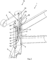
- FIG. 1 the perspective view of a bicycle 1 is shown in the area of a frame-side head tube 2, with a front fork 3 pivotably received in the head tube 2 and a stem 4, a handlebar that can be mounted on the stem 4 is not shown.
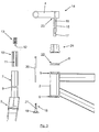
- FIG. 2 Using a sectional view according to Figure 2 a completely assembled front suspension and an exploded view Figure 3 the individual parts used in a first embodiment are explained below:
- An upper headset 5 with an upper bearing shell and a clamping ring and a lower headset 6 are accommodated in the frame-side head tube 2.
- a steerer tube 7 of a front fork 3 is pivotably received in the head tube 2 or in the upper and lower headset 5, 6, an adjusting ring 8 with an internal thread being screwed onto the steerer tube 7 on an external counter-thread (the threads are not shown in detail) and on the Clamping ring of the upper headset 5 is supported, whereby a position securing of the steerer tube 7 in the head tube 2 in connection with an adjustment of a bearing play can be carried out.
- this first embodiment according to the Figures 1 to 6 it is therefore a design with a threaded headset in which the adjusting ring is screwed onto the fork shaft 7.
- an annular stop 9 with an axial bore is made in a central longitudinal region.
- a bushing as a sliding bushing 10 is fixedly mounted in the fork shaft 7, in particular pressed or screwed.
- the sliding bush 10 has a cylindrical outer surface and a tubular inner contour 11 with a square cross section, on which sliding surfaces 12 are formed by four inserted needle bearings 13.
- the front end 4 is part of a front end arrangement 14, which also has a vertical front end shaft 15 with a square outer contour assigned to the inner contour 11.
- a bore extends through the stem 15 16 with a lower bore widening that is larger in diameter as a bolt guide 17.
- a rebound stop part 18 is inserted into the fork shaft 7 from below, which is supported by a plate part 19, optionally with an elastomer pad, on the stop 9 from below in the fork shaft 7.
- the rebound stop part 18 is held with a long screw 20, which is inserted from above through the bore 16 of the stem shaft and is screwed into an internal thread of an upwardly protruding bolt 21 of the rebound stop part 18, the bolt 21 engaging the bolt guide 17.
- an elastomer ring element 24 which is cylindrical in its basic shape, is inserted as a PUR ring damper, here with circumferential annular grooves, in which, depending on the screw-in position, with corresponding opposing surfaces the screw 20 can be pre-tensioned.
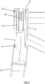
- FIG 7 A spring-loaded state of the front suspension is shown: by a driving-related force on the handlebar (not shown) and thus the front end 4, the latter is loaded from above, so that the front end shaft 15 dips further into the sliding bush 10, whereby the elastomer ring element 24 is compressed and is deformed.
- the plate part 19 of the rebound stop part 18 lifts down from the stop 9 in accordance with the deflection travel. In this way, a force load triggered from above, for example by an uneven road surface, is absorbed in an elastically damped manner, which clearly increases driving comfort.
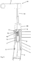
- FIG 8 a second embodiment is shown in a sectional view, in which a threadless upper headset 5 is used without an adjusting ring as a so-called ahead system.
- the fork shaft 7 protrudes upward over the head tube 2 with an overhang 25.
- This protrusion 25 is surrounded by a clamping collar 26. After the clamping collar 26 has been screwed tightly to the protrusion 25, the fork shaft 7 is secured against being pulled out downwards and the bearing play can also be adjusted.
- the elastomer ring element 24 can be inserted between the clamping collar 26 and the support surface 23 of the front end 4, whereby the remaining parts can be arranged in the fork stem 7, in particular in the protrusion 25, according to the first embodiment.
- an extension 27 for the formation of an adapter 28 is attached to the clamping collar 26 firmly connected to the top, so that the components for the front suspension, in particular the sliding bush 10 and the fork stem 7 immersed therein, are essentially arranged in the area of the adapter 28 .
- Such a front-end suspension with adapter 28 is therefore particularly well suited for equipping / retrofitting a conventional bicycle with an ahead system.
Landscapes
- Engineering & Computer Science (AREA)
- Mechanical Engineering (AREA)
- Fluid-Damping Devices (AREA)
- Vibration Prevention Devices (AREA)
Description
Die Erfindung betrifft eine Lenkvorrichtung eines Zweirads, insbesondere eines Fahrrads mit einer Vorbaufederung nach dem Oberbegriff des Anspruchs 1.The invention relates to a steering device for a two-wheeler, in particular a bicycle, with a front suspension according to the preamble of
Eine allgemein bekannte Lenkvorrichtung eines Zweirads, insbesondere eines Fahrrads weist ein rahmenseitiges Steuerrohr auf, in dem ein Gabelschaft einer Vorderradgabel schwenkbar aufgenommen ist. Als Auszugsicherung und zur Einstellung eines Lagerspiels des Gabelschafts im Steuerrohr werden ein Gewindesteuersatz, bei dem ein Einstellring auf den Gabelschaft geschraubt ist oder alternativ ein gewindeloser Steuersatz mit einer Klemmmanschette verwendet. Bei Verwendung eines Gewindesteuersatzes endet der Gabelschaft an der Oberseite des Steuerrohrs, während bei einem gewindelosen Steuersatz der Gabelschaft nach oben aus dem Steuerrohr ragt, wo er gegebenenfalls unter Zwischenschaltung von Ringen als sogenannte Spacer mittels einer Klemmmanschette des Vorbaus gehalten wird.A generally known steering device for a two-wheeled vehicle, in particular a bicycle, has a frame-side control tube in which a fork shaft of a front fork is pivotably received. A threaded headset, in which an adjusting ring is screwed onto the steerer tube, or alternatively a threadless headset with a clamping collar are used to prevent pull-out and to adjust the bearing play of the steerer tube. When using a threaded headset, the steerer tube ends at the top of the head tube, while with a threadless headset, the steerer tube protrudes upward out of the head tube, where it is held in place by means of a clamping collar of the stem with the interposition of rings as a so-called spacer.
Zur Erhöhung des Fahrkomforts sind bei einem Zweirad, insbesondere bei einem Fahrrad Federungssysteme für Vorbauten und/oder Sattelstützen und/oder Gabeln und/oder Hinterbauten allgemein bekannt. Gefederte Vorderradgabeln werden dabei meist als Teleskopgabeln ausgeführt und bestehen im Wesentlichen aus einer Gabelbrücke sowie Stand- bzw. Tauchrohren mit Federungs- und/oder Dämpfungselementen. Der Gabelschaft ist mittig auf der Gabelbrücke positioniert und schwenkbar im Lenkkopflager im Steuerrohr gelagert. Die Tauchrohre sind gegenüberliegend an der Gabelbrücke angeordnet und tauchen beim Überfahren von Fahrbahnunebenheiten und/oder Bremsmanövern in die zugeordneten Standrohre ein. Am unteren Ende der Standrohre liegt die Vorderradnabe und meist einseitig ein Bremskörper, beispielsweise eine Bremsscheibe für eine Vorderradbremse. Charakteristisch für eine solche Teleskopgabel ist der große Federweg, insbesondere bei Bremsverzögerungen, was nachteilig eine Verringerung des Nachlaufs und des Steuerwinkels zur Folge hat. Eine einseitige Montage der Vorderradbremse führt zudem nachteilig zu Verschränkungen in der Vorderradgabel beim Bremsen. Diese Eigenschaften führen zur Verringerung der Fahrstabilität und erhöhten zusätzlich den Verschleiß an den Gleitflächen der Stand- und Tauchrohre, sodass ein hoher Wartungsaufwand besteht.In order to increase the ride comfort, suspension systems for stems and / or seat posts and / or forks and / or rear structures are generally known in a two-wheeled vehicle, in particular in a bicycle. Spring-loaded front forks are mostly designed as telescopic forks and essentially consist of a fork bridge as well as standing or Immersion tubes with suspension and / or damping elements. The steerer tube is positioned in the middle of the fork bridge and pivoted in the steering head bearing in the head tube. The dip tubes are arranged opposite one another on the fork bridge and dip into the assigned standpipes when driving over uneven road surfaces and / or braking maneuvers. At the lower end of the stanchions is the front wheel hub and usually a brake body on one side, for example a brake disc for a front wheel brake. A characteristic of such a telescopic fork is the large spring deflection, especially when braking, which disadvantageously results in a reduction in the caster and the control angle. Mounting the front wheel brake on one side also disadvantageously leads to entanglements in the front wheel fork when braking. These properties lead to a reduction in driving stability and also increased wear and tear on the sliding surfaces of the standpipes and immersion tubes, so that there is a high maintenance requirement.
Weiter bekannt ist eine grundsätzlich andere Art einer Vorbaufederung, bei der keine Teleskopgabel sondern eine Starrgabel verwendet wird und der Lenker mit seinem Vorbau bezüglich des Steuerrohrs beim Überfahren von Fahrbahnunebenheiten und/oder Bremsmanövern nachgiebig rückstellend gelagert ist. Dazu weist die Vorbaufederung eine Teleskopanordnung auf, bei der eine Vorbauanordnung aus einem vertikalen Vorbauschaft und einem horizontalen, den Lenker tragenden Vorbau besteht und der Vorbauschaft im Gabelschaft verdrehfest aufgenommen und federn abgestützt ist. Die Vorbauanordnung aus dem vertikalen Vorbauschaft und dem horizontalen Vorbau kann dabei einteilig oder zweiteilig ausgeführt sein. Dazu sind Ausführungsformen bekannt (
Weiter ist eine gattungsgemäße Lenkvorrichtung eines Zweirads, insbesondere eines Fahrrads mit einer Vorbaufederung nach dem Oberbegriff des Anspruchs 1 bekannt (siehe Dokument
Aufgabe der Erfindung ist es, eine gattungsgemäße Lenkvorrichtung eines Zweirads, insbesondere eines Fahrrads mit einer Vorbaufederung durch eine einfache und funktionssichere Anordnung als Ausziehsicherung und zur Vorspannungseinstellung weiterzubilden.The object of the invention is to develop a generic steering device of a two-wheeler, in particular a bicycle with a front suspension, by means of a simple and functionally reliable arrangement as a pull-out safety device and for adjusting the preload.
Diese Aufgabe wird mit den Merkmalen des Anspruchs 1 gelöst.This object is achieved with the features of
Gemäß Anspruch 1 ist durch eine Bohrung im Vorbauschaft von oben her eine Schraube geführt, die in ein Ausfeder-Anschlagteil geschraubt ist, welches sich von unten her an einem ringförmigen Anschlag im Gabelschaft abstützt, wobei sich ein Schraubenkopf oben am Vorbau abstützt. Dieses Ausfeder-Anschlagteil hat die Funktion einer Ausziehsicherung für den Vorbauschaft nach oben. Zudem kann damit eine Vorspannung in Elastomer-Ringelement aufgebracht werden, die je nach Einschraubposition in ihrer Größe einstellbar ist. Damit kann das Ansprechverhalten der Vorbaufederung sowohl durch die Dimensionierung des Elastomer-Ringelements, hinsichtlich seiner Geometrie und des Elastomermaterials sowie durch die eingestellte Vorspannung angepasst und eingestellt werden.According to
Der Begriff "Elastomer" ist als Sammelbegriff für elastisch verformbare Materialien, insbesondere für Gummi, PUR oder ähnliche Materialien zu verstehen.The term "elastomer" is to be understood as a collective term for elastically deformable materials, in particular for rubber, PUR or similar materials.
Das Elastomer-Ringelement kann nahezu verschleiß- und wartungsfrei sein, wobei die Durchführung des Vorbauschafts durch das Elastomer-Ringelement anliegend und dicht ausgeführt werden kann, so dass keine weiteren Abdichtmaßnahmen erforderlich sind. Durch die freien Umfangsflächen des Elastomer-Ringelements kann das Elastomermaterial beim Einfedern relativ frei verformen und an den Umfangsflächen ausbeulen, so dass für eine Auslegung relativ große Freiräume zur Verfügung stehen, insbesondere auch relativ große Federwege möglich sind. Die Federwege sind hier konstruktionsbedingt zwar geringer als bei geländegängigen Zweirädern als Mountainbikes mit Teleskop-Vorderradgabeln. Mit der demgegenüber hier einfacher aufgebauten Vorbaufederung soll dagegen eine Verbesserung des Fahrkomforts bei Zweirädern, insbesondere Fahrrädern erreicht werden, die auf relativ ebenen befestigten Fahrbahnen im Stadtbereich oder über Land gefahren werden. Ein Einsatzgebiet liegt bevorzugt auch bei Elektro-Fahrrädern, sogenannten E-Bikes, welche vergleichsweise durch den Elektroantrieb schwer sind und bei denen mit einer erfindungsgemäßen Vorbaufederung der Fahrkomfort merklich gesteigert werden kann.The elastomer ring element can be virtually wear-free and maintenance-free, whereby the lead-through of the stem shaft through the elastomer ring element can be carried out in a tight and sealed manner, so that no further sealing measures are required. Due to the free circumferential surfaces of the elastomer ring element, the elastomer material can deform relatively freely during compression and bulge on the circumferential surfaces, so that relatively large free spaces are available for a design, in particular relatively large spring deflections are possible. Due to the design, the spring travel here is less than that of off-road two-wheelers than mountain bikes with telescopic front forks. With the front suspension, which is more simply constructed here, on the other hand, an improvement in the driving comfort of two-wheelers, in particular bicycles, is to be achieved be driven on relatively flat paved roadways in urban areas or over land. One area of application is preferably also in electric bicycles, so-called e-bikes, which are comparatively heavy due to the electric drive and in which the ride comfort can be significantly increased with a front suspension according to the invention.
Das Elastomer-Ringelement kann einfach aus Polyurethan als PUR-Ringdämpfer mit einer zylindrischen Grundform, gegebenenfalls mit umlaufenden Einbuchtungen ausgeführt sein. Auch das Ausfeder-Anschlagteil kann als Elastomerpuffer ausgebildet sein, bei dem insbesondere ein stabiler Kern mit Innengewinde eine Auflage aus Elastomermaterial aufweist.The elastomer ring element can simply be made of polyurethane as a PUR ring damper with a cylindrical basic shape, possibly with circumferential indentations. The rebound stop part can also be designed as an elastomer buffer, in which in particular a stable core with an internal thread has a support made of elastomer material.
Zweckmäßig weist das Elastomer-Ringelement eine obere und eine untere plane Stützfläche auf, wobei auch der Vorbau und der Einstellring oder alternativ die Klemmmanschette jeweils eine zugeordnete, etwa flächengleiche Stützfläche aufweisen.The elastomer ring element expediently has an upper and a lower planar support surface, the front end and the adjusting ring or, alternatively, the clamping sleeve also each having an associated support surface of approximately the same area.
In einer konkreten Ausgestaltung ist die verdrehfeste Teleskopanordnung dergestalt aufgebaut, dass der Vorbauschaft einen nicht kreisförmigen, vorzugsweise einen quadratischen Querschnitt als Vierkant-Schaft aufweist. Als Aufnahmekontur ist im Gabelschaft eine entsprechende rohrförmige Innenkontur fest vorhanden, in der der Vorbauschaft an Gleitflächen anliegend eintauchbar und längsverlagerbar ist. Damit kann vom Lenker über den Vorbau und den Vorbauschaft ein Lenkmoment auf den Gabelschaft, in Verbindung mit einer Längsverlagerung der Teleskopanordnung übertragen werden. Die rohrförmige Innenkontur mit den Gleitflächen wird vorzugsweise in einer Buchse zur Verfügung gestellt, die im Gabelschaft fest montiert, insbesondere verpresst oder verschraubt ist. Eine solche Buchse kann vorteilhaft in einer handelsüblichen Vorderradgabel als Erstausrüstung und gegebenenfalls auch als Nachrüstung montiert werden.In a specific embodiment, the non-rotating telescopic arrangement is constructed in such a way that the stem shaft has a non-circular, preferably a square, cross-section as a square shaft. As a receiving contour, a corresponding tubular inner contour is firmly present in the fork stem, in which the stem stem can be immersed in contact with sliding surfaces and can be longitudinally displaced. In this way, a steering torque can be transmitted from the handlebar via the stem and stem to the fork stem, in conjunction with a longitudinal displacement of the telescopic arrangement. The tubular inner contour with the sliding surfaces is preferably made available in a bushing that is firmly mounted in the fork shaft, in particular pressed or screwed. Such a socket can advantageously be installed in a commercially available front fork as original equipment and, if necessary, also as a retrofit.
Für eine leichtgängige Führung sind die Gleitflächen in der rohrförmigen Innenkontur in einer besonders bevorzugten Weiterbildung durch Nadellager gebildet. Insbesondere sind bei einem quadratischen Querschnitt der rohrförmigen Innenkontur vier entsprechend quadratisch angeordnete Nadellager verwendet mit in Axialrichtung übereinander drehbar angeordneten Nadeln.For smooth guidance, the sliding surfaces in the tubular inner contour are formed in a particularly preferred development by needle bearings. In particular, in the case of a square cross section of the tubular inner contour, four correspondingly square needle bearings are used with needles rotatably arranged one above the other in the axial direction.
Die axiale Länge des Elastomer-Ringelements kann im nicht vorgespannten Zustand zwischen 10% bis 50%, vorzugsweise zwischen 20% bis 30% der Länge des Steuerrohrs betragen, womit einerseits fahrkomfortsteigernde Federwege erreichbar sind und zudem die Vorbaufederung das übliche gewohnte Erscheinungsbild des gesamten Zweirads nicht ungünstig verändert.The axial length of the elastomer ring element in the non-pretensioned state can be between 10% to 50%, preferably between 20% to 30% of the length of the head tube, which on the one hand enables comfort-increasing spring travel to be achieved and, on the other hand, the front suspension does not have the usual appearance of the entire two-wheeler changed unfavorably.
Wie bereits ausgeführt, ist die erfindungsgemäße Vorbaufederung sowohl in Verbindung mit einem Gewindesteuersatz oder alternativ mit einer Klemmmanschette, einem sogenannten Ahead-System einsetzbar. Bei einem üblichen, allgemein bekannten Ahead-System ist die Klemmmanschette Bestandteil des Vorbaus. In Verbindung mit der erfindungsgemäßen Vorbaufederung ist die Klemmmanschette dagegen ein separates Bauteil mit darüber angeordnetem Elastomer-Ringelement und kann gegebenenfalls nach oben als Adapter verlängert werden, dergestalt dass darin der Querschnitt des Gabelschafts (nicht der Gabelschaft) nach oben weitergeführt und dort, sowie gegebenenfalls im oberen Bereich des Gabelschafts die Teleskopanordnung mit verlagerbarem Vorbauschaft, den Gleitflächen, gegebenenfalls mit einer montierten Buchse und Nadellagern, und dem Ausziehanschlag ausgebildet ist. Das Elastomer-Ringelement ist dann zwischen dem Adapter als Verlängerung der Klemmmanschette und dem Vorbau angeordnet. Eine solche Adapterausführung ist besonders einfach und kostengünstig als Nachrüstbausatz verwendbar, bei dem ein Zweirad, insbesondere ein Fahrrad in einer Werkstatt oder im Do-it-yourself-Verfahren mit einer Vorbaufederung nachrüstbar ist.As already stated, the front-end suspension according to the invention can be used both in conjunction with a threaded headset or alternatively with a clamping collar, a so-called ahead system. In a customary, well-known ahead system, the clamping collar is part of the stem. In connection with the front suspension according to the invention, however, the clamping collar is a separate component with an elastomer ring element arranged above it and can optionally be extended upwards as an adapter, in such a way that the cross section of the steerer tube (not the steerer tube) continues upwards and there, and possibly in the The telescopic arrangement with a displaceable stem shaft, the sliding surfaces, possibly with a mounted bushing and needle bearings, and the pull-out stop is formed in the upper region of the fork shaft. The elastomer ring element is then arranged between the adapter as an extension of the clamping collar and the stem. Such an adapter version can be used particularly simply and inexpensively as a retrofit kit in which a two-wheeler, in particular a bicycle can be retrofitted with a front suspension in a workshop or in the do-it-yourself process.
Anhand einer Zeichnung werden Ausführungsformen der Erfindung näher erläutert.Embodiments of the invention are explained in more detail with the aid of a drawing.
Es zeigen:
Figur 1- eine perspektivische Ansicht im Bereich eines rahmenseitigen Steuerrohrs eines Fahrrads mit einer Vorbaufederung,
Figur 2- einen vertikalen Längsschnitt der Darstellung nach
Figur 1 Figur 3- eine Explosionsdarstellung der Einzelteile,
Figuren - Schnittdarstellungen der Montagereihenfolge,
Figur 7- einem eingefederten Zustand der Vorbaufederung nach
Figur 2 Figur 8- eine Schnittdarstellung einer alternativen zweiten Ausführungsform.
- Figure 1
- a perspective view in the area of a frame-side head tube of a bicycle with a front suspension,
- Figure 2
- a vertical longitudinal section according to the illustration
Figure 1 , - Figure 3
- an exploded view of the individual parts,
- Figures 4, 5, 6
- Sectional views of the assembly sequence,
- Figure 7
- after a sprung state of the front suspension
Figure 2 , and - Figure 8
- a sectional view of an alternative second embodiment.
In
Anhand einer Schnittdarstellung nach
Im rahmenseitigen Steuerrohr 2 ist ein oberer Steuersatz 5 mit oberer Lagerschale und einem Klemmring sowie ein unterer Steuersatz 6 aufgenommen.Using a sectional view according to
An
Ein Gabelschaft 7 einer Vorderradgabel 3 ist im Steuerrohr 2 bzw. im oberen und unteren Steuersatz 5, 6 schwenkbar aufgenommen, wobei ein Einstellring 8 mit Innengewinde auf den Gabelschaft 7 auf ein Außengegengewinde geschraubt ist (die Gewinde sind nicht im Detail dargestellt) und sich am Klemmring des oberen Steuersatzes 5 abstützt, wodurch eine Lagesicherung des Gabelschafts 7 im Steuerrohr 2 in Verbindung mit einer Einstellung eines Lagerspiels durchführbar ist. Bei dieser ersten Ausführungsform nach den
Im Gabelschaft 7 ist in einem mittleren Längsbereich ein ringförmiger Anschlag 9 mit einer axialen Bohrung hergestellt. Darüber liegend ist eine Buchse als Gleitbuchse 10 fest im Gabelschaft 7 montiert, insbesondere verpresst oder verschraubt. Die Gleitbuchse 10 hat dazu eine zylindrische Außenfläche sowie eine rohrförmige Innenkontur 11 mit quadratischem Querschnitt, an der Gleitflächen 12 durch vier eingesetzte Nadellager 13 ausgebildet sind.In the
Der Vorbau 4 ist Bestandteil einer Vorbauanordnung 14, die zudem einen vertikalen Vorbauschaft 15 mit einer der Innenkontur 11 zugeordneten 4-Kant-Außenkontur aufweist. Durch den Vorbauschaft 15 erstreckt sich eine Bohrung 16 mit einem im Durchmesser größeren unteren Bohrungserweiterung als Bolzenführung 17.The
Von unten her ist in den Gabelschaft 7 ein Ausfederanschlagteil 18 eingeführt, welches sich mit einem Tellerteil 19, gegebenenfalls mit einer Elastomerauflage, am Anschlag 9 von unten hier im Gabelschaft 7 abstützt. Das Ausfederanschlagteil 18 wird mit einer langen Schraube 20 gehalten, welche von oben her durch die Bohrung 16 des Vorbauschafts gesteckt ist und in ein Innengewinde eines nach oben abstehenden Bolzens 21 des AusfederAnschlagteils 18 eingeschraubt ist, wobei der Bolzen 21 in die Bolzenführung 17 eingreift.A
Zwischen dem Einstellring 8 mit einer oberen planen Stützfläche 22 und dem Vorbau mit einer unteren planen Stützfläche 23 ist mit entsprechenden Gegenflächen ein in seiner Grundform zylindrisches Elastomer-Ringelement 24 als PUR-Ringdämpfer, hier mit umlaufenden Ringnuten, eingesetzt, in dem je nach Einschraubposition mit der Schraube 20 eine Vorspannung aufbringbar ist.Between the adjusting
Im Folgenden werden anhand von Schnittdarstellungen die einzelnen Montageschritte näher erläutert:
In
In
In
In
In
In
Zur Realisierung der erfindungsgemäßen Vorbaufederung kann das Elastomer-Ringelement 24 zwischen der Klemmmanschette 26 und der Stützfläche 23 des Vorbaus 4 eingesetzt werden, wobei die übrigen Teile entsprechend der ersten Ausführungsform im Gabelschaft 7, insbesondere im Überstand 25 angeordnet sein können.To implement the front suspension according to the invention, the
In der in
Claims (8)
- Steering device of a two-wheeled vehicle, in particular a bicycle with a handlebar stem suspension,
with a frame-side head tube (2), in which a fork stem (7) of a front wheel fork (3) is pivotably accommodated,
with a threaded headset, in which an adjustment ring (8) is screwed onto the fork stem (7), or alternatively with a threadless headset having a clamping sleeve (26) both for securing the position of the fork stem (7) in the head tube (2) and for setting a bearing play, wherein
the handlebar stem suspension comprises a telescopic arrangement, in which a handlebar stem shaft (15) of a handlebar stem arrangement (14) consisting of a vertical handlebar stem shaft (15) and a horizontal handlebar stem (4) is accommodated in a torsion-proof manner and supported resiliently in the fork stem (7),
wherein, for resiliently supporting the handlebar stem (4) between the setting ring (8) or alternatively between the clamping sleeve (26) and the handlebar stem (4), there is arranged an elastomer annular element (24) having free circumferential surfaces, through which elastomer annular element the handlebar stem shaft (15) is guided and led further into the fork stem (7) such that, in the event of a travel-induced supporting force on the handlebar stem (4), the handlebar stem shaft (15) dips into the fork stem (7), wherein the elastomer annular element (24) is deformable in a resetting manner,
characterized in that a screw (20) is guided from above through a bore in the handlebar stem shaft (15), the screw being screwed into a rebound stop part (18) which is supported from below on an annular stop (9) in the fork stem (7) as a pull-out lock and for applying an adjustable prestress on the elastomer annular element (24). - Steering device according to Claim 1, characterized in that the elastomer annular element (24) is a PUR annular damper, and/or in that the rebound stop part (18) is in the form of an elastomer buffer.
- Steering device according to Claim 1 or 2, characterized in that the elastomer annular element (24) has an upper and a lower flat supporting surface, and
in that the handlebar stem and the setting ring or alternatively the clamping sleeve in each case have an associated flat supporting surface (22, 23) of approximately identical area. - Steering device according to one of Claims 1 to 3, characterized in that the torsion-proof telescopic arrangement is constructed in such a manner that the handlebar stem shaft (15) comprises a non-circular, preferably a square cross section in the form of a square shaft, and
in that in the fork stem (7) there is a corresponding tubular inner contour (11) in which the handlebar stem shaft (15), lying on sliding surfaces (12), can dip and be displaced longitudinally. - Steering device according to Claim 4, characterized in that the tubular inner contour is produced with sliding surfaces (12), in particular with a square cross section in a bushing as a sliding bushing (10) which is mounted fixedly, in particular pressed or screwed, in the fork stem (7).
- Steering device according to Claim 4 or 5, characterized in that the sliding surfaces (12) in the tubular inner contour (10) are formed by needle bearings (13).
- Steering device according to one of Claims 1 to 6, characterized in that, in the non-prestressed state, the axial length of the elastomer annular element (24) is between 10% to 50%, preferably between 20% to 30%, of the length of the head tube (2).
- Steering device according to one of Claims 1 to 7, characterized in that, in an embodiment having a threadless headset and a clamping sleeve (26), the latter as an adapter (28) is extended upwards in such a manner that the cross section of the fork stem (7) is guided further upwards therein and there and optionally in the upper region of the fork stem (7) the telescopic arrangement having the displaceable handlebar stem shaft (15) with the sliding surfaces (12) is optionally formed in a fitted bushing (10) with needle bearings (13) and the pull-out stop (9, 18), and
in that the elastomer annular element (24) is arranged between the adapter (28) and the handlebar stem (4).
Applications Claiming Priority (1)
| Application Number | Priority Date | Filing Date | Title |
|---|---|---|---|
| DE102018002277.4A DE102018002277A1 (en) | 2018-03-20 | 2018-03-20 | Steering device of a bicycle, especially a bicycle with a Vorbaufederung |
Publications (2)
| Publication Number | Publication Date |
|---|---|
| EP3552940A1 EP3552940A1 (en) | 2019-10-16 |
| EP3552940B1 true EP3552940B1 (en) | 2020-12-16 |
Family
ID=65818328
Family Applications (1)
| Application Number | Title | Priority Date | Filing Date |
|---|---|---|---|
| EP19163439.3A Active EP3552940B1 (en) | 2018-03-20 | 2019-03-18 | Steering device of a two-wheeled vehicle, in particular a bicycle with a front suspension |
Country Status (4)
| Country | Link |
|---|---|
| EP (1) | EP3552940B1 (en) |
| DE (1) | DE102018002277A1 (en) |
| DK (1) | DK3552940T3 (en) |
| ES (1) | ES2863569T3 (en) |
Families Citing this family (2)
| Publication number | Priority date | Publication date | Assignee | Title |
|---|---|---|---|---|
| TWI741852B (en) * | 2020-10-26 | 2021-10-01 | 六哥股份有限公司 | Single-gun shock-absorbing front fork structure and shock-absorbing method thereof |
| US12269556B2 (en) * | 2022-06-10 | 2025-04-08 | Dah Ken Industrial Co., Ltd. | Stem buffer suspension assembly structure |
Family Cites Families (9)
| Publication number | Priority date | Publication date | Assignee | Title |
|---|---|---|---|---|
| CH230449A (en) * | 1942-08-27 | 1943-12-31 | Cruchet Georges | Bicycle the handlebars of which are fitted with a shock-absorbing device. |
| FR1312987A (en) | 1962-01-31 | 1962-12-21 | Moulton Consultants Ltd | Improvements to suspension systems for the front wheels of bicycles, mopeds, scooters and motorcycles |
| DE3420862A1 (en) * | 1984-06-05 | 1985-12-05 | Helmut 6638 Dillingen Mischler | Spring-mounted intermediate element for the saddles or handlebars of two-wheeled vehicles |
| FR2683010B1 (en) * | 1991-10-25 | 1995-04-21 | Daniel Dormoy | METHOD AND DEVICE FOR MOUNTING A SHOCK ABSORBER ELEMENT BETWEEN TWO CONCENTRIC MECHANICAL AXES, ONE OF WHICH IS SUBJECT TO VIBRATION. |
| DE9207057U1 (en) * | 1992-05-25 | 1992-07-30 | Kao, Weng-Ho, Shin-Tien City, Taipeh | Shock absorbing device for the front fork of a bicycle |
| CZ993U1 (en) * | 1993-02-01 | 1993-11-19 | Vladimír Vrzal | Bicycle handle-bars springing system |
| DE29715537U1 (en) * | 1997-08-29 | 1997-12-11 | Hsin Lung Accessories Co., Ltd, Hu Ko Hsiang, Hsin Chu | Shaft component with shock absorbing mechanism |
| US9994279B2 (en) | 2015-07-10 | 2018-06-12 | Specialized Bicycle Components, Inc. | Suspension assembly and bicycle having a suspension assembly |
| DE202017101030U1 (en) * | 2017-02-24 | 2017-03-09 | Dah Ken Industrial Co., Ltd. | Shock absorber for bicycle handlebars |
-
2018
- 2018-03-20 DE DE102018002277.4A patent/DE102018002277A1/en not_active Withdrawn
-
2019
- 2019-03-18 EP EP19163439.3A patent/EP3552940B1/en active Active
- 2019-03-18 DK DK19163439.3T patent/DK3552940T3/en active
- 2019-03-18 ES ES19163439T patent/ES2863569T3/en active Active
Non-Patent Citations (1)
| Title |
|---|
| None * |
Also Published As
| Publication number | Publication date |
|---|---|
| ES2863569T3 (en) | 2021-10-11 |
| DK3552940T3 (en) | 2021-03-01 |
| EP3552940A1 (en) | 2019-10-16 |
| DE102018002277A1 (en) | 2019-09-26 |
Similar Documents
| Publication | Publication Date | Title |
|---|---|---|
| EP3403910B1 (en) | Ram drive, in particular for a motor vehicle | |
| DE69017920T2 (en) | Motorbike with height-adjustable body. | |
| EP3412928B1 (en) | Shock absorbing device, in particular for a motor vehicle | |
| EP1970227A2 (en) | Wheel suspension for motor vehicles | |
| EP3552940A1 (en) | Steering device of a two-wheeled vehicle, in particular a bicycle with a front suspension | |
| EP1159186A1 (en) | Spring fork and bicycle, motorcycle or tricycle with a spring fork | |
| DE3301707A1 (en) | HYDRAULIC TELESCOPIC SHOCK ABSORBER FOR A MOTOR VEHICLE, ESPECIALLY FOR A MOTORCYCLE | |
| EP1964695B1 (en) | Pneumatic spring and damping unit with operating element | |
| DE3502579A1 (en) | Height adjusting device | |
| EP1002675A1 (en) | Suspension strut for wheel suspensions | |
| DE10128676B4 (en) | bicycle frame | |
| DE19713671C2 (en) | Front fork shock absorber for road bikes | |
| EP4019381B1 (en) | Steering rod for two-wheeled vehicle | |
| EP4046899B1 (en) | Scooter, in particular electric scooter | |
| DE202019101448U1 (en) | Level adjustment for motorcycles | |
| DE3242830A1 (en) | SPRING FRONT SUSPENSION FOR MOTORCYCLES | |
| DE112020006907T5 (en) | shock absorber | |
| DE102013106899A1 (en) | Steering bearings | |
| WO2020120752A1 (en) | Arrangement for securing a vibration damper of a vehicle | |
| DE102011053613B3 (en) | Shock strut for chassis of model jet, has upper part at which linkage is arranged, where linkage is formed as two-arm lever and vibration damper is arranged between upper part and long lever arm of linkage | |
| DE29515660U1 (en) | Bicycle suspension | |
| DE2626392A1 (en) | Damper mounting for independent suspension | |
| DE29909138U1 (en) | Suspension, swiveling seat post with cushioning | |
| DE102025125022A1 (en) | NEGATIVE AIR SPRING VOLUME SEAL FOR AIR SPRING ARRANGEMENT | |
| DE102006008992A1 (en) | Sprung fork for bicycle, includes three linear needle bearings running in tracks of molding fixed to fork shaft having commercially-standard dimensions |
Legal Events
| Date | Code | Title | Description |
|---|---|---|---|
| PUAI | Public reference made under article 153(3) epc to a published international application that has entered the european phase |
Free format text: ORIGINAL CODE: 0009012 |
|
| STAA | Information on the status of an ep patent application or granted ep patent |
Free format text: STATUS: THE APPLICATION HAS BEEN PUBLISHED |
|
| AK | Designated contracting states |
Kind code of ref document: A1 Designated state(s): AL AT BE BG CH CY CZ DE DK EE ES FI FR GB GR HR HU IE IS IT LI LT LU LV MC MK MT NL NO PL PT RO RS SE SI SK SM TR |
|
| AX | Request for extension of the european patent |
Extension state: BA ME |
|
| STAA | Information on the status of an ep patent application or granted ep patent |
Free format text: STATUS: REQUEST FOR EXAMINATION WAS MADE |
|
| 17P | Request for examination filed |
Effective date: 20200325 |
|
| RBV | Designated contracting states (corrected) |
Designated state(s): AL AT BE BG CH CY CZ DE DK EE ES FI FR GB GR HR HU IE IS IT LI LT LU LV MC MK MT NL NO PL PT RO RS SE SI SK SM TR |
|
| GRAP | Despatch of communication of intention to grant a patent |
Free format text: ORIGINAL CODE: EPIDOSNIGR1 |
|
| STAA | Information on the status of an ep patent application or granted ep patent |
Free format text: STATUS: GRANT OF PATENT IS INTENDED |
|
| INTG | Intention to grant announced |
Effective date: 20200714 |
|
| GRAS | Grant fee paid |
Free format text: ORIGINAL CODE: EPIDOSNIGR3 |
|
| GRAA | (expected) grant |
Free format text: ORIGINAL CODE: 0009210 |
|
| STAA | Information on the status of an ep patent application or granted ep patent |
Free format text: STATUS: THE PATENT HAS BEEN GRANTED |
|
| AK | Designated contracting states |
Kind code of ref document: B1 Designated state(s): AL AT BE BG CH CY CZ DE DK EE ES FI FR GB GR HR HU IE IS IT LI LT LU LV MC MK MT NL NO PL PT RO RS SE SI SK SM TR |
|
| REG | Reference to a national code |
Ref country code: GB Ref legal event code: FG4D Free format text: NOT ENGLISH |
|
| REG | Reference to a national code |
Ref country code: IE Ref legal event code: FG4D Free format text: LANGUAGE OF EP DOCUMENT: GERMAN |
|
| REG | Reference to a national code |
Ref country code: DE Ref legal event code: R096 Ref document number: 502019000524 Country of ref document: DE |
|
| REG | Reference to a national code |
Ref country code: AT Ref legal event code: REF Ref document number: 1345349 Country of ref document: AT Kind code of ref document: T Effective date: 20210115 |
|
| REG | Reference to a national code |
Ref country code: DK Ref legal event code: T3 Effective date: 20210226 |
|
| REG | Reference to a national code |
Ref country code: NL Ref legal event code: FP |
|
| PG25 | Lapsed in a contracting state [announced via postgrant information from national office to epo] |
Ref country code: GR Free format text: LAPSE BECAUSE OF FAILURE TO SUBMIT A TRANSLATION OF THE DESCRIPTION OR TO PAY THE FEE WITHIN THE PRESCRIBED TIME-LIMIT Effective date: 20210317 Ref country code: NO Free format text: LAPSE BECAUSE OF FAILURE TO SUBMIT A TRANSLATION OF THE DESCRIPTION OR TO PAY THE FEE WITHIN THE PRESCRIBED TIME-LIMIT Effective date: 20210316 Ref country code: RS Free format text: LAPSE BECAUSE OF FAILURE TO SUBMIT A TRANSLATION OF THE DESCRIPTION OR TO PAY THE FEE WITHIN THE PRESCRIBED TIME-LIMIT Effective date: 20201216 Ref country code: FI Free format text: LAPSE BECAUSE OF FAILURE TO SUBMIT A TRANSLATION OF THE DESCRIPTION OR TO PAY THE FEE WITHIN THE PRESCRIBED TIME-LIMIT Effective date: 20201216 |
|
| PGFP | Annual fee paid to national office [announced via postgrant information from national office to epo] |
Ref country code: FR Payment date: 20210226 Year of fee payment: 3 |
|
| PG25 | Lapsed in a contracting state [announced via postgrant information from national office to epo] |
Ref country code: BG Free format text: LAPSE BECAUSE OF FAILURE TO SUBMIT A TRANSLATION OF THE DESCRIPTION OR TO PAY THE FEE WITHIN THE PRESCRIBED TIME-LIMIT Effective date: 20210316 Ref country code: LV Free format text: LAPSE BECAUSE OF FAILURE TO SUBMIT A TRANSLATION OF THE DESCRIPTION OR TO PAY THE FEE WITHIN THE PRESCRIBED TIME-LIMIT Effective date: 20201216 Ref country code: SE Free format text: LAPSE BECAUSE OF FAILURE TO SUBMIT A TRANSLATION OF THE DESCRIPTION OR TO PAY THE FEE WITHIN THE PRESCRIBED TIME-LIMIT Effective date: 20201216 |
|
| PGFP | Annual fee paid to national office [announced via postgrant information from national office to epo] |
Ref country code: DK Payment date: 20210225 Year of fee payment: 3 |
|
| PG25 | Lapsed in a contracting state [announced via postgrant information from national office to epo] |
Ref country code: HR Free format text: LAPSE BECAUSE OF FAILURE TO SUBMIT A TRANSLATION OF THE DESCRIPTION OR TO PAY THE FEE WITHIN THE PRESCRIBED TIME-LIMIT Effective date: 20201216 |
|
| REG | Reference to a national code |
Ref country code: LT Ref legal event code: MG9D |
|
| PG25 | Lapsed in a contracting state [announced via postgrant information from national office to epo] |
Ref country code: CZ Free format text: LAPSE BECAUSE OF FAILURE TO SUBMIT A TRANSLATION OF THE DESCRIPTION OR TO PAY THE FEE WITHIN THE PRESCRIBED TIME-LIMIT Effective date: 20201216 Ref country code: EE Free format text: LAPSE BECAUSE OF FAILURE TO SUBMIT A TRANSLATION OF THE DESCRIPTION OR TO PAY THE FEE WITHIN THE PRESCRIBED TIME-LIMIT Effective date: 20201216 Ref country code: SK Free format text: LAPSE BECAUSE OF FAILURE TO SUBMIT A TRANSLATION OF THE DESCRIPTION OR TO PAY THE FEE WITHIN THE PRESCRIBED TIME-LIMIT Effective date: 20201216 Ref country code: SM Free format text: LAPSE BECAUSE OF FAILURE TO SUBMIT A TRANSLATION OF THE DESCRIPTION OR TO PAY THE FEE WITHIN THE PRESCRIBED TIME-LIMIT Effective date: 20201216 Ref country code: RO Free format text: LAPSE BECAUSE OF FAILURE TO SUBMIT A TRANSLATION OF THE DESCRIPTION OR TO PAY THE FEE WITHIN THE PRESCRIBED TIME-LIMIT Effective date: 20201216 Ref country code: PT Free format text: LAPSE BECAUSE OF FAILURE TO SUBMIT A TRANSLATION OF THE DESCRIPTION OR TO PAY THE FEE WITHIN THE PRESCRIBED TIME-LIMIT Effective date: 20210416 Ref country code: LT Free format text: LAPSE BECAUSE OF FAILURE TO SUBMIT A TRANSLATION OF THE DESCRIPTION OR TO PAY THE FEE WITHIN THE PRESCRIBED TIME-LIMIT Effective date: 20201216 |
|
| PG25 | Lapsed in a contracting state [announced via postgrant information from national office to epo] |
Ref country code: PL Free format text: LAPSE BECAUSE OF FAILURE TO SUBMIT A TRANSLATION OF THE DESCRIPTION OR TO PAY THE FEE WITHIN THE PRESCRIBED TIME-LIMIT Effective date: 20201216 |
|
| REG | Reference to a national code |
Ref country code: DE Ref legal event code: R097 Ref document number: 502019000524 Country of ref document: DE |
|
| PG25 | Lapsed in a contracting state [announced via postgrant information from national office to epo] |
Ref country code: IS Free format text: LAPSE BECAUSE OF FAILURE TO SUBMIT A TRANSLATION OF THE DESCRIPTION OR TO PAY THE FEE WITHIN THE PRESCRIBED TIME-LIMIT Effective date: 20210416 |
|
| REG | Reference to a national code |
Ref country code: ES Ref legal event code: FG2A Ref document number: 2863569 Country of ref document: ES Kind code of ref document: T3 Effective date: 20211011 |
|
| PLBE | No opposition filed within time limit |
Free format text: ORIGINAL CODE: 0009261 |
|
| STAA | Information on the status of an ep patent application or granted ep patent |
Free format text: STATUS: NO OPPOSITION FILED WITHIN TIME LIMIT |
|
| PG25 | Lapsed in a contracting state [announced via postgrant information from national office to epo] |
Ref country code: MC Free format text: LAPSE BECAUSE OF FAILURE TO SUBMIT A TRANSLATION OF THE DESCRIPTION OR TO PAY THE FEE WITHIN THE PRESCRIBED TIME-LIMIT Effective date: 20201216 Ref country code: AL Free format text: LAPSE BECAUSE OF FAILURE TO SUBMIT A TRANSLATION OF THE DESCRIPTION OR TO PAY THE FEE WITHIN THE PRESCRIBED TIME-LIMIT Effective date: 20201216 |
|
| 26N | No opposition filed |
Effective date: 20210917 |
|
| PG25 | Lapsed in a contracting state [announced via postgrant information from national office to epo] |
Ref country code: IE Free format text: LAPSE BECAUSE OF NON-PAYMENT OF DUE FEES Effective date: 20210318 Ref country code: LU Free format text: LAPSE BECAUSE OF NON-PAYMENT OF DUE FEES Effective date: 20210318 |
|
| PG25 | Lapsed in a contracting state [announced via postgrant information from national office to epo] |
Ref country code: SI Free format text: LAPSE BECAUSE OF FAILURE TO SUBMIT A TRANSLATION OF THE DESCRIPTION OR TO PAY THE FEE WITHIN THE PRESCRIBED TIME-LIMIT Effective date: 20201216 |
|
| PGFP | Annual fee paid to national office [announced via postgrant information from national office to epo] |
Ref country code: BE Payment date: 20220331 Year of fee payment: 4 |
|
| PGFP | Annual fee paid to national office [announced via postgrant information from national office to epo] |
Ref country code: IT Payment date: 20220331 Year of fee payment: 4 Ref country code: ES Payment date: 20220404 Year of fee payment: 4 |
|
| REG | Reference to a national code |
Ref country code: DK Ref legal event code: EBP Effective date: 20220331 |
|
| REG | Reference to a national code |
Ref country code: CH Ref legal event code: PL |
|
| REG | Reference to a national code |
Ref country code: NL Ref legal event code: MM Effective date: 20220401 |
|
| PG25 | Lapsed in a contracting state [announced via postgrant information from national office to epo] |
Ref country code: NL Free format text: LAPSE BECAUSE OF NON-PAYMENT OF DUE FEES Effective date: 20220401 Ref country code: LI Free format text: LAPSE BECAUSE OF NON-PAYMENT OF DUE FEES Effective date: 20220331 Ref country code: FR Free format text: LAPSE BECAUSE OF NON-PAYMENT OF DUE FEES Effective date: 20220331 Ref country code: CH Free format text: LAPSE BECAUSE OF NON-PAYMENT OF DUE FEES Effective date: 20220331 |
|
| PG25 | Lapsed in a contracting state [announced via postgrant information from national office to epo] |
Ref country code: DK Free format text: LAPSE BECAUSE OF NON-PAYMENT OF DUE FEES Effective date: 20220331 |
|
| PG25 | Lapsed in a contracting state [announced via postgrant information from national office to epo] |
Ref country code: CY Free format text: LAPSE BECAUSE OF FAILURE TO SUBMIT A TRANSLATION OF THE DESCRIPTION OR TO PAY THE FEE WITHIN THE PRESCRIBED TIME-LIMIT Effective date: 20201216 |
|
| PG25 | Lapsed in a contracting state [announced via postgrant information from national office to epo] |
Ref country code: HU Free format text: LAPSE BECAUSE OF FAILURE TO SUBMIT A TRANSLATION OF THE DESCRIPTION OR TO PAY THE FEE WITHIN THE PRESCRIBED TIME-LIMIT; INVALID AB INITIO Effective date: 20190318 |
|
| GBPC | Gb: european patent ceased through non-payment of renewal fee |
Effective date: 20230318 |
|
| REG | Reference to a national code |
Ref country code: BE Ref legal event code: MM Effective date: 20230331 |
|
| PG25 | Lapsed in a contracting state [announced via postgrant information from national office to epo] |
Ref country code: GB Free format text: LAPSE BECAUSE OF NON-PAYMENT OF DUE FEES Effective date: 20230318 |
|
| PG25 | Lapsed in a contracting state [announced via postgrant information from national office to epo] |
Ref country code: GB Free format text: LAPSE BECAUSE OF NON-PAYMENT OF DUE FEES Effective date: 20230318 |
|
| PG25 | Lapsed in a contracting state [announced via postgrant information from national office to epo] |
Ref country code: BE Free format text: LAPSE BECAUSE OF NON-PAYMENT OF DUE FEES Effective date: 20230331 |
|
| PG25 | Lapsed in a contracting state [announced via postgrant information from national office to epo] |
Ref country code: ES Free format text: LAPSE BECAUSE OF NON-PAYMENT OF DUE FEES Effective date: 20230319 |
|
| REG | Reference to a national code |
Ref country code: ES Ref legal event code: FD2A Effective date: 20240426 |
|
| PG25 | Lapsed in a contracting state [announced via postgrant information from national office to epo] |
Ref country code: MK Free format text: LAPSE BECAUSE OF FAILURE TO SUBMIT A TRANSLATION OF THE DESCRIPTION OR TO PAY THE FEE WITHIN THE PRESCRIBED TIME-LIMIT Effective date: 20201216 Ref country code: IT Free format text: LAPSE BECAUSE OF NON-PAYMENT OF DUE FEES Effective date: 20230318 Ref country code: ES Free format text: LAPSE BECAUSE OF NON-PAYMENT OF DUE FEES Effective date: 20230319 |
|
| PG25 | Lapsed in a contracting state [announced via postgrant information from national office to epo] |
Ref country code: MT Free format text: LAPSE BECAUSE OF FAILURE TO SUBMIT A TRANSLATION OF THE DESCRIPTION OR TO PAY THE FEE WITHIN THE PRESCRIBED TIME-LIMIT Effective date: 20201216 |
|
| REG | Reference to a national code |
Ref country code: AT Ref legal event code: MM01 Ref document number: 1345349 Country of ref document: AT Kind code of ref document: T Effective date: 20240318 |
|
| PG25 | Lapsed in a contracting state [announced via postgrant information from national office to epo] |
Ref country code: AT Free format text: LAPSE BECAUSE OF NON-PAYMENT OF DUE FEES Effective date: 20240318 |
|
| PG25 | Lapsed in a contracting state [announced via postgrant information from national office to epo] |
Ref country code: TR Free format text: LAPSE BECAUSE OF FAILURE TO SUBMIT A TRANSLATION OF THE DESCRIPTION OR TO PAY THE FEE WITHIN THE PRESCRIBED TIME-LIMIT Effective date: 20201216 |
|
| PGFP | Annual fee paid to national office [announced via postgrant information from national office to epo] |
Ref country code: DE Payment date: 20260325 Year of fee payment: 8 |
|
| PGFP | Annual fee paid to national office [announced via postgrant information from national office to epo] |
Ref country code: AT Payment date: 20260410 Year of fee payment: 5 |