EP4046841A1 - Fahrgestellrahmenmodul für elektrofahrzeug - Google Patents
Fahrgestellrahmenmodul für elektrofahrzeug Download PDFInfo
- Publication number
- EP4046841A1 EP4046841A1 EP22157607.7A EP22157607A EP4046841A1 EP 4046841 A1 EP4046841 A1 EP 4046841A1 EP 22157607 A EP22157607 A EP 22157607A EP 4046841 A1 EP4046841 A1 EP 4046841A1
- Authority
- EP
- European Patent Office
- Prior art keywords
- cage
- wire
- clip
- chassis frame
- frame
- Prior art date
- Legal status (The legal status is an assumption and is not a legal conclusion. Google has not performed a legal analysis and makes no representation as to the accuracy of the status listed.)
- Granted
Links
Images


Classifications
-
- B—PERFORMING OPERATIONS; TRANSPORTING
- B60—VEHICLES IN GENERAL
- B60K—ARRANGEMENT OR MOUNTING OF PROPULSION UNITS OR OF TRANSMISSIONS IN VEHICLES; ARRANGEMENT OR MOUNTING OF PLURAL DIVERSE PRIME-MOVERS IN VEHICLES; AUXILIARY DRIVES FOR VEHICLES; INSTRUMENTATION OR DASHBOARDS FOR VEHICLES; ARRANGEMENTS IN CONNECTION WITH COOLING, AIR INTAKE, GAS EXHAUST OR FUEL SUPPLY OF PROPULSION UNITS IN VEHICLES
- B60K1/00—Arrangement or mounting of electrical propulsion units
- B60K1/04—Arrangement or mounting of electrical propulsion units of the electric storage means for propulsion
-
- B—PERFORMING OPERATIONS; TRANSPORTING
- B62—LAND VEHICLES FOR TRAVELLING OTHERWISE THAN ON RAILS
- B62D—MOTOR VEHICLES; TRAILERS
- B62D21/00—Understructures, i.e. chassis frame on which a vehicle body may be mounted
- B62D21/02—Understructures, i.e. chassis frame on which a vehicle body may be mounted comprising longitudinally or transversely arranged frame members
-
- B—PERFORMING OPERATIONS; TRANSPORTING
- B62—LAND VEHICLES FOR TRAVELLING OTHERWISE THAN ON RAILS
- B62D—MOTOR VEHICLES; TRAILERS
- B62D21/00—Understructures, i.e. chassis frame on which a vehicle body may be mounted
- B62D21/07—Understructures, i.e. chassis frame on which a vehicle body may be mounted wide-hipped frame type, i.e. a wide box-shaped mid portion with narrower sections extending from said mid portion in both fore and aft directions
-
- B—PERFORMING OPERATIONS; TRANSPORTING
- B62—LAND VEHICLES FOR TRAVELLING OTHERWISE THAN ON RAILS
- B62D—MOTOR VEHICLES; TRAILERS
- B62D25/00—Superstructure or monocoque structure sub-units; Parts or details thereof not otherwise provided for
- B62D25/20—Floors or bottom sub-units
- B62D25/2009—Floors or bottom sub-units in connection with other superstructure subunits
- B62D25/2018—Floors or bottom sub-units in connection with other superstructure subunits the subunits being front structures
-
- B—PERFORMING OPERATIONS; TRANSPORTING
- B62—LAND VEHICLES FOR TRAVELLING OTHERWISE THAN ON RAILS
- B62D—MOTOR VEHICLES; TRAILERS
- B62D25/00—Superstructure or monocoque structure sub-units; Parts or details thereof not otherwise provided for
- B62D25/20—Floors or bottom sub-units
- B62D25/2009—Floors or bottom sub-units in connection with other superstructure subunits
- B62D25/2027—Floors or bottom sub-units in connection with other superstructure subunits the subunits being rear structures
-
- B—PERFORMING OPERATIONS; TRANSPORTING
- B62—LAND VEHICLES FOR TRAVELLING OTHERWISE THAN ON RAILS
- B62D—MOTOR VEHICLES; TRAILERS
- B62D25/00—Superstructure or monocoque structure sub-units; Parts or details thereof not otherwise provided for
- B62D25/20—Floors or bottom sub-units
- B62D25/2009—Floors or bottom sub-units in connection with other superstructure subunits
- B62D25/2036—Floors or bottom sub-units in connection with other superstructure subunits the subunits being side panels, sills or pillars
-
- B—PERFORMING OPERATIONS; TRANSPORTING
- B60—VEHICLES IN GENERAL
- B60K—ARRANGEMENT OR MOUNTING OF PROPULSION UNITS OR OF TRANSMISSIONS IN VEHICLES; ARRANGEMENT OR MOUNTING OF PLURAL DIVERSE PRIME-MOVERS IN VEHICLES; AUXILIARY DRIVES FOR VEHICLES; INSTRUMENTATION OR DASHBOARDS FOR VEHICLES; ARRANGEMENTS IN CONNECTION WITH COOLING, AIR INTAKE, GAS EXHAUST OR FUEL SUPPLY OF PROPULSION UNITS IN VEHICLES
- B60K1/00—Arrangement or mounting of electrical propulsion units
- B60K1/04—Arrangement or mounting of electrical propulsion units of the electric storage means for propulsion
- B60K2001/0405—Arrangement or mounting of electrical propulsion units of the electric storage means for propulsion characterised by their position
- B60K2001/0438—Arrangement under the floor
-
- B—PERFORMING OPERATIONS; TRANSPORTING
- B60—VEHICLES IN GENERAL
- B60Y—INDEXING SCHEME RELATING TO ASPECTS CROSS-CUTTING VEHICLE TECHNOLOGY
- B60Y2306/00—Other features of vehicle sub-units
- B60Y2306/01—Reducing damages in case of crash, e.g. by improving battery protection
-
- B—PERFORMING OPERATIONS; TRANSPORTING
- B60—VEHICLES IN GENERAL
- B60Y—INDEXING SCHEME RELATING TO ASPECTS CROSS-CUTTING VEHICLE TECHNOLOGY
- B60Y2410/00—Constructional features of vehicle sub-units
- B60Y2410/115—Electric wiring; Electric connectors
Definitions
- Exemplary embodiments of the present disclosure relate to a chassis frame module for an electric vehicle, and more particularly, to a chassis frame module for an electric vehicle, in which a wire assembly for containing a wire can be modularized as a unit part to follow the expandability of the specification of a vehicle.
- an electric vehicle refers to a vehicle which drives by using electricity as power, and acquires driving energy by rotating a motor using electricity stored in a battery.
- PBV Purpose Built Vehicle
- Various embodiments are directed to a chassis frame module for an electric vehicle, in which a wire assembly for containing a wire can be modularized as a unit part to follow the expandability of the specification of a vehicle.
- various embodiments are directed to a chassis frame module for an electrical vehicle, which can improve the coupling performance of a wire to a chassis frame module.
- a chassis frame module for an electric vehicle may include: a chassis frame comprising a pair of side frames; a pair of inclined frames connected to front ends of the respective side frames, respectively, and a distance between the pair of inclined frames decreases toward the front; a front frame connected to the inclined frames; and a rear frame connected to rear ends of the pair of side frames; a battery disposed between the pair of side frames; and a plurality of wire assemblies disposed between the side frame and the battery and in a longitudinal direction of the side frame, and being configured to house a wire in an internal space thereof.
- the plurality of wire assemblies each may include: a cage disposed between the side frame and the battery, and in the longitudinal direction of the side frame; and a clip having one side supported by the cage and the other side connected to the side frame.
- the cage may include: a cage body formed in a hollow shape, and being configured to house the wire in an internal space thereof; a cage holding part formed on one side of the cage body, and configured to hold a neighboring cage body; a cage insertion part formed on the other side of the cage body, and inserted into the neighboring cage body; and a lever inserted into one side of the cage holding part, and configured to expand an opening of the cage holding part.
- the width of an inner surface of the cage holding part may decrease toward an inside of the cage body, and a width of an outer surface of the cage insertion part may decrease toward an outside of the cage body.
- the lever may include: a first lever support part supported by one surface of the cage body; a second lever support part extending from the first lever support part and being inserted into one side of the cage holding part; and a lever manipulation part extending from the second lever support part, and being configured to be pressed to turn the second lever support part to expand an opening of the cage holding part.
- the cage holding part may have an insertion hole formed therein, the cage body has a protrusion formed on an outer surface thereof, and the protrusion is inserted into the insertion hole of a neighboring cage holding part.
- the clip may include: a clip body having one side supported by the cage body and the other side connected to the side frame; and a clip through part mounted on one surface of the clip body, inserted into the cage body, and being configured to support the wire.
- the plurality of wire assemblies each may further include a clip fitting part having one open side to surround an outer surface of the wire and the other side placed on an outer surface of the clip through part.
- the wire may include: a wire body inserted into an internal space of the cage body; a first wire end part mounted on one side of the wire body and having the clip fitting part mounted on an outer surface thereof; and a second wire end part mounted on the other side of the wire body and inserted into a neighboring first wire end part.
- the cage may be made of a plastic material.
- a chassis frame module for an electric vehicle may include: a chassis frame comprising a pair of side frames; a pair of inclined frames connected to front ends of the side frames, respectively, such that a distance therebetween decreases toward the front; a front frame connected to the inclined frames; and a rear frame configured to connect rear ends of the side frames; a battery disposed between the pair of side frames; and a wire assembly connected to the side frame and the battery, and being configured to contain a wire in an internal space thereof.
- the wire assembly may include: a wire cage having one side connected to the side frame and the other side connected to the battery; and a clip mounted in the wire cage, such that the wire is seated thereon.
- the clip may be detachably mounted on the wire cage.
- the clip may include: a clip insertion part mounted on the wire cage; a clip rod part extended from one side of the clip insertion part; a contact surface part mounted at an end of the clip rod part, and being in contact with the wire cage; and an elastic coupling part formed on one side of the contact surface part, having a ring shape with an open side, and being elastically coupled to the wire.
- the clip insertion part may be formed in an arrowhead shape whose size gradually decreases in an insertion direction to the wire cage, and being made of an elastically deformable material.
- the wire cage may include: a wire body having one side connected to the side frame and the other side connected to the battery; and having an internal space formed therein; and a grid part mounted in the internal space of the cage body, formed in a grid shape, and configured to divide a space in which the plurality of clips are mounted.
- the wire cage may further include a plurality of open observation windows formed in the cage body along the length of the cage body.
- the wire cage may be made of a plastic material.
- the wire may be housed in the wire assembly which connects the side frame and the battery.
- the space efficiency of the chassis frame module may be increased so that the chassis frame module can be manufactured in a shape proper to the concept of the vehicle.
- the wire assemblies may be applied to the side frame which is modified according to the specification and concept of the vehicle.
- the wire may be housed in the wire assembly, which makes it possible to reduce the corrosion of the wire, caused by the exposure to the outside.
- the wire assembly may be interposed between the side frame and the battery.
- the wire assembly can disperse a collision load and reduce the damage to the battery, thereby reducing an occurrence of accident such as a fire.
- chassis frame module for an electric vehicle will be described below with reference to the accompanying drawings through various exemplary embodiments. It should be noted that the drawings are not to precise scale and may be exaggerated in thickness of lines or sizes of components for descriptive convenience and clarity only.
- FIG. 1 is a perspective view schematically illustrating a chassis frame module for an electrical vehicle in accordance with an embodiment of the present disclosure
- FIG. 2 is a partially expanded perspective view schematically illustrating a portion "A" of FIG. 1
- FIG. 3 is an assembled perspective view schematically illustrating the chassis frame module for an electrical vehicle in accordance with the embodiment of the present disclosure
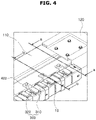
- FIG. 4 is a partially expanded perspective view schematically illustrating a portion "B" of FIG. 3
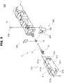
- FIG. 5 is a partially expanded perspective view schematically illustrating a portion "C" of FIG. 3
- FIG. 6 is a perspective view schematically illustrating one side of a cage in accordance with the embodiment of the present disclosure
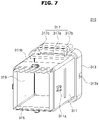
- FIG. 7 is a perspective view schematically illustrating the other side of the cage in accordance with the embodiment of the present disclosure
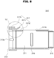
- FIG. 8 is a cross-sectional view schematically illustrating the cage in accordance with the embodiment of the present disclosure
- FIG. 9 is a partially expanded cross-sectional view schematically illustrating a portion "D" of FIG. 8
- FIG. 10 is a cross-sectional view taken along line a-a of FIG. 4
- FIG. 11 is a cross-sectional view taken along line b-b of FIG. 4 .
- the chassis frame module for an electric vehicle in accordance with the embodiment of the present disclosure includes a chassis frame 100, a battery 200 and a wire assembly 300.
- the chassis frame 100 serves to support the bottom of a vehicle body (not illustrated), and protect the vehicle body from a vehicle accident or the like.
- the chassis frame 100 includes a side frame 110, an inclined frame 120, a front frame 130 and a rear frame 140.
- the chassis frame 100 may be made of a metal or elastic fiber.
- the chassis frame 100 may be made of a metal including a light metal or a metal including elastic fiber, and thus improve the strength and hardness of the vehicle and improve the fuel efficiency of the vehicle, while reducing the weight of the vehicle.
- Examples of the light metal included in the chassis frame 100 may include aluminum, magnesium and the like.
- the vehicle body is a structure of the vehicle, which is designed to contain and protect mechanical parts, passengers and freight, and has a shape that is decided according to the use and size of the vehicle or the like.
- the vehicle body is seated on the top of the chassis frame to support the vehicle body.
- the side frame 110 is provided as a pair of side frames which are spaced apart from each other in the widthwise direction (side-to-side direction in FIG. 1 ) of the vehicle body such that the battery 200 is disposed therebetween, and the vehicle body is seated on the pair of side frames.
- An extruded material e.g. aluminum or the like
- manufactured through an extrusion method may be used for the side frame 110.
- the inclined frame 120 is provided as a pair of inclined frames connected to the respective front ends (right ends in FIG. 1 ) of the pair of side frames 110.
- the pair of inclined frames are installed so as to be inclined in directions facing each other, such that the distance therebetween gradually decreases toward the front (to the right in FIG. 1 ).
- An extruded material e.g. aluminum or the like
- manufactured through an extrusion method may be used for the inclined frame 120.
- the front frame 130 is connected to the inclined frames 120, and disposed at the front (right in FIG. 1 ) of the vehicle.
- An extruded material e.g. aluminum or the like
- An extrusion method may be used for the front frame 130.
- the rear frame 140 serves to connect the rear ends of the side frames 110, and is disposed at the front (left in FIG. 1 ) of the vehicle body.
- An extruded material e.g. aluminum or the like
- An extrusion method may be used for the rear frame 140.
- the battery 200 is installed on the chassis frame 100, and serves to store electric power and supply the electric power to the vehicle.
- the battery 200 is disposed between the pair of side frames 110 in the chassis frame 100.
- the wire assembly 300 is disposed between the side frame 110 and the battery 200, is provided as a plurality of wire assemblies disposed in the longitudinal direction of the side frame 110, and serves to contain a wire in an internal space thereof.
- the plurality of wire assemblies 300 are each modularized to have a preset length, and disposed in the longitudinal direction of the side frame 110 so as to correspond to the length L of the side frame 110. As the plurality of wire assemblies 300 are modularized and disposed according to the length L of the side frame 110, the wire assemblies 300 may be applied to various side frames 110 which are modified according to the specification and concept of the vehicle.
- the wire assembly 300 may contain a wire 10 therein such that the wire 10 is not exposed to the outside, which makes it possible to prevent corrosion of the wire 10.
- the wire assembly 300 is connected to the side frame 110 by a fastener 400.
- the wire assembly 300 includes a cage 310 and a clip 320.
- the cage 310 is disposed between the side frame 110 and the battery 200, and provided as a plurality of cages which are disposed in the longitudinal direction of the side frame 110 so as to correspond to the length L of the side frame 110.
- the number of the cages 310 may be set to a value corresponding to the length of the side frame 110, such that the cages 310 can be applied to various side frames 110 which are modified according to the specification of the vehicle.
- the cage 310 includes a cage body 311, a cage holding part 313, a cage insertion part 315 and a lever 317.
- the cage body 311 is formed in a hollow shape, and houses the wire 10 in the internal space thereof.
- the cage body 311 is provided as a plurality of cage bodies disposed in the longitudinal direction of the side frame 110, and the neighboring cage bodies 311 are coupled to each other as one body.
- the cage holding part 313 is formed on one side (left side in FIG. 5 ) of the cage body 311, and serves to hold the neighboring cage body 311. That is, the cage holding part 313 of the cage 310 holds the cage insertion part 315 of the neighboring cage 310 disposed on the left side in FIG. 5 .
- the cage insertion part 315 is formed on the other side (right side in FIG. 5 ) of the cage body 311, and inserted into the neighboring cage body 311. That is, the cage insertion part 315 of the cage 310 is inserted into the cage holding part 313 of the neighboring cage 310 disposed on the right side in FIG. 5 .
- the lever 317 is inserted into one side (left side in FIG. 8 ) of the cage holding part 313, and serves to expand an opening of the cage holding part 313.
- the cage insertion part 315 inserted into the cage holding part 313 may be separated from the cage holding part 313.
- the inner surface of the cage holding part 313 has a width that decreases toward the inside of the cage body 311, and the outer surface of the cage insertion part 315 has a width that decreases toward the outside of the cage body 311.
- the cage insertion part 315 may be easily inserted or introduced into the cage holding part 313.
- the cage holding part 313 has an insertion hole 313a
- the cage body 311 has a protrusion 311a formed on the outer surface thereof.
- the protrusion 311a is inserted into the insertion hole 313a of the neighboring cage holding part 313.
- the cage body 311 has an open surface 311b formed on one side (top side in FIG. 5 ) thereof. Through the open surface 311b, a clip fitting part 330 is inserted into the cage body 311.
- the lever 317 includes a first lever support part 317a, a second lever support part 317b and a lever manipulation part 317c.
- the first lever support part 317a is supported by one surface (left top surface in FIG. 8 ) of the cage body 311.
- the second lever support part 317b is extended from the first lever support part 317a to the left (based on FIG. 8 ), and inserted into one side (left side in FIG. 8 ) of the cage holding part 313.
- the lever manipulation part 317c is extended from the second lever support part 317b, and pressed to turn the second lever support part 317b, thereby expanding the opening of the cage holding part 313.
- the second lever support part 317b connected to the lever manipulation part 317c is also turned in the clockwise direction to expand the opening of the cage holding part 313.
- the protrusion 311a is separated from the insertion hole 313a, and the connected cages 310 are separated from each other.
- the wire cage 310 is made of a plastic material having preset strength and hardness.
- the preset strength and hardness of the wire cage 310 indicate strength and hardness which are set to such an extent that the wire cage 310 can connect the battery 200 and the side frame 110 while supporting the weight of the battery 200, and can be broken when external shock equal to or more than a preset level of shock is transferred from the side frame 110, thereby buffering the shock transferred to the battery 200.
- the wire cage 310 may be broken by shock transferred from the side frame 110, and disperse a collision load. As a result, the wire cage 310 may reduce the damage to the battery 200, thereby reducing an occurrence of accident such as a fire.
- the clip 320 has one side (left side in FIG. 5 ) supported by the cage 310 and the other side (right side in FIG. 5 ) connected to the side frame 110.
- the clip 320 includes a clip body 321 and a clip through part 323.
- the clip body 321 has one side (bottom side in FIG. 5 ) supported by the cage body 311 and the other side (top side in FIG. 5 ) connected to the side frame 110.
- the clip body 321 is formed in a shape similar to the S-shape.
- the other side of the clip body 321 is fixedly connected to the side frame 110 by the fastener 400.
- the clip through part 323 is mounted on one surface (right surface in FIG. 5 ) of the clip body 321 and inserted into the cage body 311, and serves to support the wire 10.
- the clip through part 323 has a hole formed in the center thereof, such that the wire 10 is inserted into the hole formed in the center of the clip through part 323 to support the wire 10.
- the cage 310 further includes a slit 319 formed through a side surface of the cage body 311.
- the clip through part 323 is inserted into the clip body 321 through the slit 319 of the cage 310.
- the wire assembly 300 further includes the clip fitting part 330.
- One side (bottom side in FIG. 5 ) of the clip fitting part 330 is open to surround the outer surface of the wire 10, and the other side of the clip fitting part 330 is placed on the outer surface of the clip through part 323.
- the other side of the clip fitting part 330 is formed in a ring shape, and hooked and placed on the outer surface of the clip through part 323.
- the clip fitting part 330 surrounds the outer surface of the wire 10 and thus prevents the separation of the wire 10.
- the wire 10 is provided as a plurality of wires which correspond to the modularized wire assemblies 300 and are used as connectable power connections or pipes.
- the wire 10 includes a wire body 11, a first wire end part 13 and a second wire end part 15.
- the wire body 11 is formed in a rod shape with a preset length.
- the first wire end part 13 is mounted on one side (left side in FIG. 5 ) of the wire body 11, and has an outer surface on which the clip fitting part 330 is mounted.
- the second wire end part 15 is mounted on the other side (right side in FIG. 5 ) of the wire body 11, and inserted into the first wire end part 13 of the neighboring wire body 11 disposed on the right side in FIG. 5 .
- the wire 10 may be housed in the wire assembly 300 which connects the side frame 110 and the battery 200.
- the space efficiency of the chassis frame module may be increased so that the chassis frame module can be manufactured in a shape proper to the concept of the vehicle.
- the wire assemblies 300 may be applied to the side frame 110 which is modified according to the specification and concept of the vehicle.
- the wire 10 may be housed in the wire assembly 300, which makes it possible to reduce the corrosion of the wire, caused by the exposure to the outside.
- the wire assembly 300 may be interposed between the side frame 110 and the battery 200.
- the wire assembly 300 can disperse a collision load and reduce the damage to the battery 200, thereby reducing an occurrence of accident such as a fire.
- FIG. 12 is a perspective view schematically illustrating a chassis frame module for an electric vehicle in accordance with another embodiment of the present disclosure
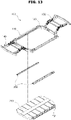
- FIG. 13 is an assembled perspective view schematically illustrating the chassis frame module for an electric vehicle in accordance with the another embodiment of the present disclosure
- FIG. 14 is a perspective view schematically illustrating a wire assembly in accordance with the another embodiment of the present disclosure
- FIG. 15 is an assembled perspective view schematically illustrating the wire assembly in accordance with the another embodiment of the present disclosure
- FIG. 16 is a partially expanded perspective view schematically illustrating a portion "C" of FIG. 15
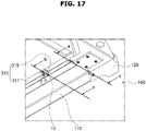
- FIG. 17 is a partially expanded perspective view schematically illustrating a portion "A" of FIG. 12
- FIG. 18 is a schematic cross-sectional view taken along line a-a of FIG. 17
- FIG. 19 is a schematic cross-sectional view taken along line b-b of FIG. 17
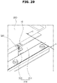
- FIG. 20 is a partially expanded perspective view schematically illustrating a portion "B" of FIG. 13
- FIG. 21 is a schematic cross-sectional view taken along line c-c of FIG. 20 .
- a chassis frame module for an electric vehicle in accordance with another embodiment of the present disclosure includes a chassis frame 100, a battery 200, and a wire assembly 300.
- the chassis frame 100 serves to support the bottom of a vehicle body (not illustrated), and protect the vehicle body from a vehicle accident or the like.
- the chassis frame 100 includes a side frame 110, an inclined frame 120, a front frame 130 and a rear frame 140.
- the chassis frame 100 may be made of a metal or elastic fiber.
- the chassis frame 100 may be made of a light metal or a metal including elastic fiber, and thus improve the strength and hardness of the vehicle and improve the fuel efficiency of the vehicle, while reducing the weight of the vehicle.
- Examples of the light metal included in the chassis frame 100 may include aluminum, magnesium and the like.
- the vehicle body is a structure of the vehicle, which is designed to contain and protect mechanical parts, passengers and freight, and has a shape decided according to the use and size of the vehicle or the like.
- the vehicle body is seated on the top of the chassis frame to support the vehicle body.
- the side frame 110 is provided as a pair of side frames which are spaced apart from each other in the widthwise direction (side-to-side direction in FIG. 12 ) of the vehicle body such that the battery 200 is disposed therebetween, and the vehicle body is seated on the pair of side frames.
- An extruded material e.g. aluminum or the like
- manufactured through an extrusion method may be used for the side frame 110.
- the inclined frame 120 is provided as a pair of inclined frames connected to the respective front ends (right ends in FIG. 12 ) of the pair of side frames 110.
- the pair of inclined frames are installed so as to be inclined in directions facing each other, such that the distance therebetween gradually decreases toward the front (to the right in FIG. 12 ).
- An extruded material e.g. aluminum or the like
- manufactured through an extrusion method may be used for the inclined frame 120.
- the front frame 130 is connected to the inclined frames 120, and disposed at the front (right in FIG. 12 ) of the vehicle body.
- An extruded material e.g. aluminum or the like
- An extrusion method may be used for the front frame 130.
- the rear frame 140 serves to connect the rear ends of the side frames 110, and is disposed at the rear (left in FIG. 12 ) of the vehicle body.
- An extruded material e.g. aluminum or the like
- An extrusion method may be used for the rear frame 140.
- the battery 200 is installed on the chassis frame 100, and serves to store electric power and supply the electric power to the vehicle.
- the battery 200 is disposed between the pair of side frames 110 in the chassis frame 100.
- the wire assembly 300 is connected to the side frame 110 and the battery 200, and contains a wire 10 in an internal space thereof.
- the wire 10 may be contained in the wire assembly 300 so as not to be exposed to the outside, which makes it possible to prevent corrosion of the wire 10.
- the wire assembly 300 is connected to the side frame 110 by a fastener 400.
- the wire assembly 300 includes a wire cage 310 and a clip 320.
- the wire cage 310 has one side (right side in FIG. 14 ) connected to the side frame 110 and the other side (left side in FIG. 14 ) connected to the battery 200.
- the wire cage 310 has an internal space in which the wire 10 is contained.
- the wire assembly 300 is disposed between the side frame 110 and the battery 200.
- the clip 320 of the wire assembly 300 is coupled to the side frame 110, and the wire cage 310 of the wire assembly 300 is assembled and fixed to the outer wall of the battery 200 with the clip 320.
- the wire cage 310 includes a cage body 311 and a grid part 313.
- the cage body 311 has one side (right side in FIG. 14 ) connected to the side frame 110 and the other side (left side in FIG. 14 ) connected to the battery 200, and has an internal space formed therein.
- the wire 10 is inserted and contained in the internal space of the hollow wire cage 310.
- the grid part 313 is mounted in the internal space of the cage body 311, and formed in a grid shape to divide the space in which a plurality of clips 320 are mounted. That is, the grid part 313 has a cross-shaped cross-section.
- the cross-shaped grid part 313 may form four divided spaces, and the plurality of clips 320 may be mounted in the respective divided spaces.
- the plurality of wires 10 mounted on the clips 320 are separately disposed so as not to overlap each other.
- the wire cage 310 is made of a plastic material having preset strength and hardness.
- the preset strength and hardness of the wire cage 310 indicate strength and hardness which are set to such an extent that the wire cage 310 can connect the battery 200 and the side frame 110 while supporting the weight of the battery 200, and can be broken when external shock equal to or more than a preset level of shock is applied from the side frame 110, thereby buffering the shock applied to the battery 200.
- the wire cage 310 may be broken by shock applied from the side frame 110, and disperse a collision load. As a result, the wire cage 310 may reduce the damage to the battery 200, thereby reducing an occurrence of accident such as a fire.
- the wire cage 310 further includes an observation window 315.
- the observation window 315 is provided as a plurality of observation windows 315 formed in the cage body 311 along the length of the cage body 311.
- the observation window 315 is open toward the side frame 110 from the cage body 311. Through the open observation window 315, an operator may confirm whether the wire 10 is inserted and contained into the cage body 311, and check whether the wire 10 is normally mounted on the clip 320 mounted in the cage body 311.
- the clip 320 is mounted in the wire cage 310, such that the wire 10 is seated on the clip 320.
- the clip 320 having the wire 10 seated thereon prevents the separation of the wire 10.
- the clip 320 is detachably mounted in the wire cage 310. As the clip 320 is detachably mounted in the wire cage 310, the clip 320 may be easily assembled to/separated from the wire cage 310, such that an operator can perform repair or replacement.
- the clip 320 includes a clip insertion part 321, a clip rod part 323, a contact surface part 325, and an elastic coupling part 327.
- the clip insertion part 321 is mounted on the cage body 311 of the wire cage 310.
- the clip insertion part 321 is detachably mounted on the cage body 311 of the wire cage 310.
- the clip insertion part 321 is formed in an arrowhead shape whose size gradually decreases in the insertion direction to the wire cage 310, and made of an elastically deformable material.
- the clip insertion part 321 is formed in an arrowhead shape whose size gradually decreases in the insertion direction to the wire cage 310, and thus easily inserted into the cage body 311 of the wire cage 310.
- the clip insertion part 321 is made of an elastically deformable material. Therefore, the clip insertion part 321 is compressed when inserted into the cage body 311 of the wire cage 310, and then elastically restored after the insertion into the cage body 311 of the wire cage 310. Thus, the clip insertion part 321 may be prevented from being separated from the cage body 311.
- the clip rod part 323 is extended from one side (right side in FIG. 16 ) of the clip insertion part 321, and formed in a rod shape with a preset length.
- the clip rod part 323 connects the clip insertion part 321 and the contact surface part 325, and is inserted into a through-hole of the cage body 311.
- the contact surface part 325 is mounted at an end (right end in FIG. 16 ) of the clip rod part 323, and comes into contact with one surface of the cage body 311 of the wire cage 310.
- the contact surface part 325 comes in contact with the one surface of the cage body 311 of the wire cage 310, and thus serves as a stopper to restrict the movement of the clip insertion part 321 and the clip rod part 323.
- the elastic coupling part 327 is formed on one side of the contact surface part 325, has a ring shape whose one side (right side in FIG. 16 ) is open, and is elastically coupled to the wire 10.
- the elastic coupling part 327 is made of a metal or plastic material. When the wire 10 is inserted into the opening of the elastic coupling part 327, the elastic coupling part 327 may be spread. Then, the elastic coupling part 327 may be retracted while surrounding the outer surface of the wire 10, and elastically coupled to the wire 10, thereby preventing the separation of the wire 10.
- the wire 10 may be contained in the wire assembly 300 which connects the side frame 110 and the battery 200.
- the space efficiency of the chassis frame module may be improved so that the chassis frame module can be manufactured in a shape proper to the concept of the vehicle.
- the wire 10 may be contained in the wire assembly 300, which makes it possible to reduce the corrosion of the wire 10, caused by the exposure to the outside.
- the wire assembly 300 may be interposed between the side frame 110 and the battery 200.
- the wire assembly 300 can disperse a collision load and reduce the damage to the battery 200, thereby reducing the occurrence of accident such as a fire.
Landscapes
- Engineering & Computer Science (AREA)
- Chemical & Material Sciences (AREA)
- Combustion & Propulsion (AREA)
- Transportation (AREA)
- Mechanical Engineering (AREA)
- Battery Mounting, Suspending (AREA)
- Body Structure For Vehicles (AREA)
Applications Claiming Priority (2)
| Application Number | Priority Date | Filing Date | Title |
|---|---|---|---|
| KR1020210022797A KR102958870B1 (ko) | 2021-02-19 | 전기차량용 샤시 프레임 | |
| KR1020210022796A KR102958869B1 (ko) | 2021-02-19 | 전기차량용 샤시 프레임 |
Publications (2)
| Publication Number | Publication Date |
|---|---|
| EP4046841A1 true EP4046841A1 (de) | 2022-08-24 |
| EP4046841B1 EP4046841B1 (de) | 2024-11-06 |
Family
ID=81326230
Family Applications (1)
| Application Number | Title | Priority Date | Filing Date |
|---|---|---|---|
| EP22157607.7A Active EP4046841B1 (de) | 2021-02-19 | 2022-02-18 | Fahrgestellrahmenmodul für elektrofahrzeug |
Country Status (3)
| Country | Link |
|---|---|
| US (1) | US11713079B2 (de) |
| EP (1) | EP4046841B1 (de) |
| CN (1) | CN216709422U (de) |
Cited By (1)
| Publication number | Priority date | Publication date | Assignee | Title |
|---|---|---|---|---|
| FR3151805A1 (fr) * | 2023-08-03 | 2025-02-07 | Psa Automobiles Sa | Vehicule automobile comprenant une entretoise de fixation de cables de servitude, et procede sur la base d’un tel vehicule |
Families Citing this family (9)
| Publication number | Priority date | Publication date | Assignee | Title |
|---|---|---|---|---|
| DE102018213517A1 (de) * | 2018-08-10 | 2020-02-13 | Bayerische Motoren Werke Aktiengesellschaft | Batteriespeicheranordnung, Verwendung eines Trägers, Verfahren zum Montieren einer Batteriespeicheranordnung sowie Arbeitsvorrichtung |
| KR102792069B1 (ko) * | 2020-09-01 | 2025-04-08 | 현대모비스 주식회사 | 전기차용 섀시 플랫폼 모듈 |
| US11713079B2 (en) * | 2021-02-19 | 2023-08-01 | Hyundai Mobis Co., Ltd. | Chassis frame module for electric vehicle |
| US12409718B2 (en) * | 2021-09-09 | 2025-09-09 | Oshkosh Corporation | Structural refuse vehicle body with undermounted batteries |
| US12233946B2 (en) * | 2021-09-30 | 2025-02-25 | Mazda Motor Corporation | Vehicle-body structure including a cross member at a rear portion of the floor panel |
| JP2023122984A (ja) * | 2022-02-24 | 2023-09-05 | マツダ株式会社 | 後部車体構造 |
| FR3138802B1 (fr) * | 2022-08-10 | 2026-04-17 | Psa Automobiles Sa | Véhicule terrestre à éléments de structure adaptés à des variations de longueur de parties de plancher |
| US12447808B2 (en) * | 2022-10-14 | 2025-10-21 | Ford Global Technologies, Llc | Structural assembly and vehicle having structural assembly |
| USD1104863S1 (en) * | 2023-06-09 | 2025-12-09 | Shanghai Windrose Automotive Technology Co., Ltd. | Truck frame |
Citations (8)
| Publication number | Priority date | Publication date | Assignee | Title |
|---|---|---|---|---|
| DE4417470C1 (de) * | 1994-05-19 | 1995-05-04 | Daimler Benz Ag | Fahrgastzelle mit einem in einen Freiraum einlegbaren Kabelbaum |
| EP1939026A1 (de) * | 2006-12-28 | 2008-07-02 | Mitsubishi Jidosha Kogyo Kabushiki Kaisha | Struktur zur Montage von Batterien auf elektrische Fahrzeuge |
| US8596685B2 (en) * | 2010-07-23 | 2013-12-03 | Renault S.A.S. | Motor vehicle chassis having a part for attaching bodywork elements and electrical cables to the central floor |
| JP2014101009A (ja) * | 2012-11-20 | 2014-06-05 | Aisin Keikinzoku Co Ltd | 電池保護構造体 |
| US20200079202A1 (en) * | 2018-09-12 | 2020-03-12 | Honda Motor Co., Ltd. | Vehicle |
| KR102089486B1 (ko) | 2018-07-19 | 2020-03-16 | 주식회사 한국쓰리축 | 전기차용 샤시플랫폼 모듈 |
| US20200406976A1 (en) * | 2019-06-25 | 2020-12-31 | Toyota Jidosha Kabushiki Kaisha | Vehicle structure of frame vehicle |
| US20200406978A1 (en) * | 2019-06-28 | 2020-12-31 | Toyota Jidosha Kabushiki Kaisha | Vehcile lower portion structure |
Family Cites Families (8)
| Publication number | Priority date | Publication date | Assignee | Title |
|---|---|---|---|---|
| JP3086642B2 (ja) * | 1995-10-23 | 2000-09-11 | 矢崎総業株式会社 | ジョイントコネクタ |
| US6270150B1 (en) * | 1998-12-15 | 2001-08-07 | Great Dane Limited Partnership | Trailer with conduit retainer |
| US7270346B2 (en) * | 2004-09-27 | 2007-09-18 | Oshkosh Truck Corporation | Vehicle frame |
| JP5968687B2 (ja) * | 2012-06-12 | 2016-08-10 | プレス工業株式会社 | 車体フレームの配管配線構造 |
| US10112563B2 (en) * | 2015-06-30 | 2018-10-30 | Faraday & Future Inc. | Tapered crush can |
| JP2017076500A (ja) * | 2015-10-14 | 2017-04-20 | 住友電装株式会社 | ワイヤハーネス |
| DE102019107504B4 (de) * | 2019-03-25 | 2023-05-11 | Bayerische Motoren Werke Aktiengesellschaft | Energiespeicher für einen Kraftwagen |
| US11713079B2 (en) * | 2021-02-19 | 2023-08-01 | Hyundai Mobis Co., Ltd. | Chassis frame module for electric vehicle |
-
2022
- 2022-02-17 US US17/674,386 patent/US11713079B2/en active Active
- 2022-02-18 CN CN202220334519.3U patent/CN216709422U/zh active Active
- 2022-02-18 EP EP22157607.7A patent/EP4046841B1/de active Active
Patent Citations (8)
| Publication number | Priority date | Publication date | Assignee | Title |
|---|---|---|---|---|
| DE4417470C1 (de) * | 1994-05-19 | 1995-05-04 | Daimler Benz Ag | Fahrgastzelle mit einem in einen Freiraum einlegbaren Kabelbaum |
| EP1939026A1 (de) * | 2006-12-28 | 2008-07-02 | Mitsubishi Jidosha Kogyo Kabushiki Kaisha | Struktur zur Montage von Batterien auf elektrische Fahrzeuge |
| US8596685B2 (en) * | 2010-07-23 | 2013-12-03 | Renault S.A.S. | Motor vehicle chassis having a part for attaching bodywork elements and electrical cables to the central floor |
| JP2014101009A (ja) * | 2012-11-20 | 2014-06-05 | Aisin Keikinzoku Co Ltd | 電池保護構造体 |
| KR102089486B1 (ko) | 2018-07-19 | 2020-03-16 | 주식회사 한국쓰리축 | 전기차용 샤시플랫폼 모듈 |
| US20200079202A1 (en) * | 2018-09-12 | 2020-03-12 | Honda Motor Co., Ltd. | Vehicle |
| US20200406976A1 (en) * | 2019-06-25 | 2020-12-31 | Toyota Jidosha Kabushiki Kaisha | Vehicle structure of frame vehicle |
| US20200406978A1 (en) * | 2019-06-28 | 2020-12-31 | Toyota Jidosha Kabushiki Kaisha | Vehcile lower portion structure |
Cited By (1)
| Publication number | Priority date | Publication date | Assignee | Title |
|---|---|---|---|---|
| FR3151805A1 (fr) * | 2023-08-03 | 2025-02-07 | Psa Automobiles Sa | Vehicule automobile comprenant une entretoise de fixation de cables de servitude, et procede sur la base d’un tel vehicule |
Also Published As
| Publication number | Publication date |
|---|---|
| EP4046841B1 (de) | 2024-11-06 |
| CN216709422U (zh) | 2022-06-10 |
| US11713079B2 (en) | 2023-08-01 |
| US20220266907A1 (en) | 2022-08-25 |
Similar Documents
| Publication | Publication Date | Title |
|---|---|---|
| EP4046841A1 (de) | Fahrgestellrahmenmodul für elektrofahrzeug | |
| US10093249B2 (en) | Electric device mounting structure | |
| JP4935112B2 (ja) | 蓄電パックの車載構造 | |
| JP5821387B2 (ja) | 車両のインバータ搭載構造 | |
| US11394071B2 (en) | Battery assembly structure | |
| EP1361099A2 (de) | Antriebsstranglagerung | |
| JP2009274666A (ja) | 蓄電装置の支持構造 | |
| CN111769220A (zh) | 用于车辆牵引电池系统的安装支架 | |
| JP6293783B2 (ja) | 自動車のクレードルのための連結装置 | |
| EP1264724A3 (de) | Anordnung einer Fahrzeugantriebseinheit und Methode | |
| CN108422844A (zh) | 车辆 | |
| JP2020032857A (ja) | 車両 | |
| JP6546982B2 (ja) | 自動車両のためのエネルギ供給システム及び自動車両 | |
| KR20140021889A (ko) | 차량용 배터리 트레이 | |
| US11104383B2 (en) | Vehicle front portion structure | |
| US20210107354A1 (en) | Mounting system for powertrain of vehicle | |
| CN111391922B (zh) | 电动汽车车架 | |
| US10165704B2 (en) | External power feeding apparatus | |
| KR102939182B1 (ko) | 고전압배터리를 탑재하는 차량의 차체 | |
| EP3722186A1 (de) | Querträger für fahrzeugboden, fahrzeugboden, formteil aus aluminiumlegierung und fahrzeug | |
| KR102958870B1 (ko) | 전기차량용 샤시 프레임 | |
| JP4325554B2 (ja) | ドア構造 | |
| KR20220118839A (ko) | 전기차량용 샤시 프레임 | |
| KR20220118838A (ko) | 전기차량용 샤시 프레임 | |
| US11377046B2 (en) | Vehicle with toilet |
Legal Events
| Date | Code | Title | Description |
|---|---|---|---|
| PUAI | Public reference made under article 153(3) epc to a published international application that has entered the european phase |
Free format text: ORIGINAL CODE: 0009012 |
|
| STAA | Information on the status of an ep patent application or granted ep patent |
Free format text: STATUS: REQUEST FOR EXAMINATION WAS MADE |
|
| 17P | Request for examination filed |
Effective date: 20220318 |
|
| AK | Designated contracting states |
Kind code of ref document: A1 Designated state(s): AL AT BE BG CH CY CZ DE DK EE ES FI FR GB GR HR HU IE IS IT LI LT LU LV MC MK MT NL NO PL PT RO RS SE SI SK SM TR |
|
| RBV | Designated contracting states (corrected) |
Designated state(s): AL AT BE BG CH CY CZ DE DK EE ES FI FR GB GR HR HU IE IS IT LI LT LU LV MC MK MT NL NO PL PT RO RS SE SI SK SM TR |
|
| GRAP | Despatch of communication of intention to grant a patent |
Free format text: ORIGINAL CODE: EPIDOSNIGR1 |
|
| STAA | Information on the status of an ep patent application or granted ep patent |
Free format text: STATUS: GRANT OF PATENT IS INTENDED |
|
| RIC1 | Information provided on ipc code assigned before grant |
Ipc: B62D 25/20 20060101ALI20240606BHEP Ipc: B62D 21/07 20060101ALI20240606BHEP Ipc: B60K 1/04 20190101AFI20240606BHEP |
|
| INTG | Intention to grant announced |
Effective date: 20240621 |
|
| GRAS | Grant fee paid |
Free format text: ORIGINAL CODE: EPIDOSNIGR3 |
|
| GRAA | (expected) grant |
Free format text: ORIGINAL CODE: 0009210 |
|
| STAA | Information on the status of an ep patent application or granted ep patent |
Free format text: STATUS: THE PATENT HAS BEEN GRANTED |
|
| AK | Designated contracting states |
Kind code of ref document: B1 Designated state(s): AL AT BE BG CH CY CZ DE DK EE ES FI FR GB GR HR HU IE IS IT LI LT LU LV MC MK MT NL NO PL PT RO RS SE SI SK SM TR |
|
| REG | Reference to a national code |
Ref country code: GB Ref legal event code: FG4D |
|
| P01 | Opt-out of the competence of the unified patent court (upc) registered |
Free format text: CASE NUMBER: APP_53447/2024 Effective date: 20240926 |
|
| REG | Reference to a national code |
Ref country code: CH Ref legal event code: EP |
|
| REG | Reference to a national code |
Ref country code: DE Ref legal event code: R096 Ref document number: 602022007341 Country of ref document: DE |
|
| REG | Reference to a national code |
Ref country code: IE Ref legal event code: FG4D |
|
| REG | Reference to a national code |
Ref country code: LT Ref legal event code: MG9D |
|
| REG | Reference to a national code |
Ref country code: NL Ref legal event code: MP Effective date: 20241106 |
|
| PG25 | Lapsed in a contracting state [announced via postgrant information from national office to epo] |
Ref country code: IS Free format text: LAPSE BECAUSE OF FAILURE TO SUBMIT A TRANSLATION OF THE DESCRIPTION OR TO PAY THE FEE WITHIN THE PRESCRIBED TIME-LIMIT Effective date: 20250306 Ref country code: PT Free format text: LAPSE BECAUSE OF FAILURE TO SUBMIT A TRANSLATION OF THE DESCRIPTION OR TO PAY THE FEE WITHIN THE PRESCRIBED TIME-LIMIT Effective date: 20250306 Ref country code: HR Free format text: LAPSE BECAUSE OF FAILURE TO SUBMIT A TRANSLATION OF THE DESCRIPTION OR TO PAY THE FEE WITHIN THE PRESCRIBED TIME-LIMIT Effective date: 20241106 |
|
| PG25 | Lapsed in a contracting state [announced via postgrant information from national office to epo] |
Ref country code: FI Free format text: LAPSE BECAUSE OF FAILURE TO SUBMIT A TRANSLATION OF THE DESCRIPTION OR TO PAY THE FEE WITHIN THE PRESCRIBED TIME-LIMIT Effective date: 20241106 Ref country code: NL Free format text: LAPSE BECAUSE OF FAILURE TO SUBMIT A TRANSLATION OF THE DESCRIPTION OR TO PAY THE FEE WITHIN THE PRESCRIBED TIME-LIMIT Effective date: 20241106 |
|
| REG | Reference to a national code |
Ref country code: AT Ref legal event code: MK05 Ref document number: 1739017 Country of ref document: AT Kind code of ref document: T Effective date: 20241106 |
|
| PG25 | Lapsed in a contracting state [announced via postgrant information from national office to epo] |
Ref country code: BG Free format text: LAPSE BECAUSE OF FAILURE TO SUBMIT A TRANSLATION OF THE DESCRIPTION OR TO PAY THE FEE WITHIN THE PRESCRIBED TIME-LIMIT Effective date: 20241106 |
|
| PG25 | Lapsed in a contracting state [announced via postgrant information from national office to epo] |
Ref country code: ES Free format text: LAPSE BECAUSE OF FAILURE TO SUBMIT A TRANSLATION OF THE DESCRIPTION OR TO PAY THE FEE WITHIN THE PRESCRIBED TIME-LIMIT Effective date: 20241106 |
|
| PG25 | Lapsed in a contracting state [announced via postgrant information from national office to epo] |
Ref country code: NO Free format text: LAPSE BECAUSE OF FAILURE TO SUBMIT A TRANSLATION OF THE DESCRIPTION OR TO PAY THE FEE WITHIN THE PRESCRIBED TIME-LIMIT Effective date: 20250206 |
|
| PG25 | Lapsed in a contracting state [announced via postgrant information from national office to epo] |
Ref country code: LV Free format text: LAPSE BECAUSE OF FAILURE TO SUBMIT A TRANSLATION OF THE DESCRIPTION OR TO PAY THE FEE WITHIN THE PRESCRIBED TIME-LIMIT Effective date: 20241106 Ref country code: GR Free format text: LAPSE BECAUSE OF FAILURE TO SUBMIT A TRANSLATION OF THE DESCRIPTION OR TO PAY THE FEE WITHIN THE PRESCRIBED TIME-LIMIT Effective date: 20250207 Ref country code: AT Free format text: LAPSE BECAUSE OF FAILURE TO SUBMIT A TRANSLATION OF THE DESCRIPTION OR TO PAY THE FEE WITHIN THE PRESCRIBED TIME-LIMIT Effective date: 20241106 |
|
| PG25 | Lapsed in a contracting state [announced via postgrant information from national office to epo] |
Ref country code: PL Free format text: LAPSE BECAUSE OF FAILURE TO SUBMIT A TRANSLATION OF THE DESCRIPTION OR TO PAY THE FEE WITHIN THE PRESCRIBED TIME-LIMIT Effective date: 20241106 |
|
| PG25 | Lapsed in a contracting state [announced via postgrant information from national office to epo] |
Ref country code: RS Free format text: LAPSE BECAUSE OF FAILURE TO SUBMIT A TRANSLATION OF THE DESCRIPTION OR TO PAY THE FEE WITHIN THE PRESCRIBED TIME-LIMIT Effective date: 20250206 |
|
| PG25 | Lapsed in a contracting state [announced via postgrant information from national office to epo] |
Ref country code: SM Free format text: LAPSE BECAUSE OF FAILURE TO SUBMIT A TRANSLATION OF THE DESCRIPTION OR TO PAY THE FEE WITHIN THE PRESCRIBED TIME-LIMIT Effective date: 20241106 |
|
| PG25 | Lapsed in a contracting state [announced via postgrant information from national office to epo] |
Ref country code: DK Free format text: LAPSE BECAUSE OF FAILURE TO SUBMIT A TRANSLATION OF THE DESCRIPTION OR TO PAY THE FEE WITHIN THE PRESCRIBED TIME-LIMIT Effective date: 20241106 |
|
| PG25 | Lapsed in a contracting state [announced via postgrant information from national office to epo] |
Ref country code: EE Free format text: LAPSE BECAUSE OF FAILURE TO SUBMIT A TRANSLATION OF THE DESCRIPTION OR TO PAY THE FEE WITHIN THE PRESCRIBED TIME-LIMIT Effective date: 20241106 |
|
| PG25 | Lapsed in a contracting state [announced via postgrant information from national office to epo] |
Ref country code: RO Free format text: LAPSE BECAUSE OF FAILURE TO SUBMIT A TRANSLATION OF THE DESCRIPTION OR TO PAY THE FEE WITHIN THE PRESCRIBED TIME-LIMIT Effective date: 20241106 |
|
| PG25 | Lapsed in a contracting state [announced via postgrant information from national office to epo] |
Ref country code: SK Free format text: LAPSE BECAUSE OF FAILURE TO SUBMIT A TRANSLATION OF THE DESCRIPTION OR TO PAY THE FEE WITHIN THE PRESCRIBED TIME-LIMIT Effective date: 20241106 |
|
| PG25 | Lapsed in a contracting state [announced via postgrant information from national office to epo] |
Ref country code: CZ Free format text: LAPSE BECAUSE OF FAILURE TO SUBMIT A TRANSLATION OF THE DESCRIPTION OR TO PAY THE FEE WITHIN THE PRESCRIBED TIME-LIMIT Effective date: 20241106 |
|
| PG25 | Lapsed in a contracting state [announced via postgrant information from national office to epo] |
Ref country code: IT Free format text: LAPSE BECAUSE OF FAILURE TO SUBMIT A TRANSLATION OF THE DESCRIPTION OR TO PAY THE FEE WITHIN THE PRESCRIBED TIME-LIMIT Effective date: 20241106 |
|
| REG | Reference to a national code |
Ref country code: DE Ref legal event code: R097 Ref document number: 602022007341 Country of ref document: DE |
|
| PG25 | Lapsed in a contracting state [announced via postgrant information from national office to epo] |
Ref country code: SE Free format text: LAPSE BECAUSE OF FAILURE TO SUBMIT A TRANSLATION OF THE DESCRIPTION OR TO PAY THE FEE WITHIN THE PRESCRIBED TIME-LIMIT Effective date: 20241106 |
|
| PLBE | No opposition filed within time limit |
Free format text: ORIGINAL CODE: 0009261 |
|
| STAA | Information on the status of an ep patent application or granted ep patent |
Free format text: STATUS: NO OPPOSITION FILED WITHIN TIME LIMIT |
|
| PG25 | Lapsed in a contracting state [announced via postgrant information from national office to epo] |
Ref country code: MC Free format text: LAPSE BECAUSE OF FAILURE TO SUBMIT A TRANSLATION OF THE DESCRIPTION OR TO PAY THE FEE WITHIN THE PRESCRIBED TIME-LIMIT Effective date: 20241106 |
|
| REG | Reference to a national code |
Ref country code: CH Ref legal event code: PL |
|
| 26N | No opposition filed |
Effective date: 20250807 |
|
| PG25 | Lapsed in a contracting state [announced via postgrant information from national office to epo] |
Ref country code: LU Free format text: LAPSE BECAUSE OF NON-PAYMENT OF DUE FEES Effective date: 20250218 |
|
| PG25 | Lapsed in a contracting state [announced via postgrant information from national office to epo] |
Ref country code: CH Free format text: LAPSE BECAUSE OF NON-PAYMENT OF DUE FEES Effective date: 20250228 |
|
| REG | Reference to a national code |
Ref country code: BE Ref legal event code: MM Effective date: 20250228 |
|
| PGFP | Annual fee paid to national office [announced via postgrant information from national office to epo] |
Ref country code: GB Payment date: 20251222 Year of fee payment: 5 |
|
| PGFP | Annual fee paid to national office [announced via postgrant information from national office to epo] |
Ref country code: FR Payment date: 20251223 Year of fee payment: 5 |
|
| PG25 | Lapsed in a contracting state [announced via postgrant information from national office to epo] |
Ref country code: BE Free format text: LAPSE BECAUSE OF NON-PAYMENT OF DUE FEES Effective date: 20250228 |
|
| PG25 | Lapsed in a contracting state [announced via postgrant information from national office to epo] |
Ref country code: IE Free format text: LAPSE BECAUSE OF NON-PAYMENT OF DUE FEES Effective date: 20250218 |
|
| PGFP | Annual fee paid to national office [announced via postgrant information from national office to epo] |
Ref country code: DE Payment date: 20251222 Year of fee payment: 5 |