EP4046824B1 - Motorradreifenpaar - Google Patents
Motorradreifenpaar Download PDFInfo
- Publication number
- EP4046824B1 EP4046824B1 EP22153385.4A EP22153385A EP4046824B1 EP 4046824 B1 EP4046824 B1 EP 4046824B1 EP 22153385 A EP22153385 A EP 22153385A EP 4046824 B1 EP4046824 B1 EP 4046824B1
- Authority
- EP
- European Patent Office
- Prior art keywords
- tire
- band
- cord
- carcass
- band cord
- Prior art date
- Legal status (The legal status is an assumption and is not a legal conclusion. Google has not performed a legal analysis and makes no representation as to the accuracy of the status listed.)
- Active
Links
Images


Classifications
-
- B—PERFORMING OPERATIONS; TRANSPORTING
- B60—VEHICLES IN GENERAL
- B60C—VEHICLE TYRES; TYRE INFLATION; TYRE CHANGING; CONNECTING VALVES TO INFLATABLE ELASTIC BODIES IN GENERAL; DEVICES OR ARRANGEMENTS RELATED TO TYRES
- B60C9/00—Reinforcements or ply arrangement of pneumatic tyres
- B60C9/18—Structure or arrangement of belts or breakers, crown-reinforcing or cushioning layers
- B60C9/20—Structure or arrangement of belts or breakers, crown-reinforcing or cushioning layers built-up from rubberised plies each having all cords arranged substantially parallel
- B60C9/22—Structure or arrangement of belts or breakers, crown-reinforcing or cushioning layers built-up from rubberised plies each having all cords arranged substantially parallel the plies being arranged with all cords disposed along the circumference of the tyre
-
- B—PERFORMING OPERATIONS; TRANSPORTING
- B60—VEHICLES IN GENERAL
- B60C—VEHICLE TYRES; TYRE INFLATION; TYRE CHANGING; CONNECTING VALVES TO INFLATABLE ELASTIC BODIES IN GENERAL; DEVICES OR ARRANGEMENTS RELATED TO TYRES
- B60C9/00—Reinforcements or ply arrangement of pneumatic tyres
- B60C9/0007—Reinforcements made of metallic elements, e.g. cords, yarns, filaments or fibres made from metal
-
- B—PERFORMING OPERATIONS; TRANSPORTING
- B60—VEHICLES IN GENERAL
- B60C—VEHICLE TYRES; TYRE INFLATION; TYRE CHANGING; CONNECTING VALVES TO INFLATABLE ELASTIC BODIES IN GENERAL; DEVICES OR ARRANGEMENTS RELATED TO TYRES
- B60C9/00—Reinforcements or ply arrangement of pneumatic tyres
- B60C9/02—Carcasses
- B60C9/0238—Carcasses characterised by special physical properties of the carcass ply
-
- B—PERFORMING OPERATIONS; TRANSPORTING
- B60—VEHICLES IN GENERAL
- B60C—VEHICLE TYRES; TYRE INFLATION; TYRE CHANGING; CONNECTING VALVES TO INFLATABLE ELASTIC BODIES IN GENERAL; DEVICES OR ARRANGEMENTS RELATED TO TYRES
- B60C9/00—Reinforcements or ply arrangement of pneumatic tyres
- B60C9/0042—Reinforcements made of synthetic materials
-
- B—PERFORMING OPERATIONS; TRANSPORTING
- B60—VEHICLES IN GENERAL
- B60C—VEHICLE TYRES; TYRE INFLATION; TYRE CHANGING; CONNECTING VALVES TO INFLATABLE ELASTIC BODIES IN GENERAL; DEVICES OR ARRANGEMENTS RELATED TO TYRES
- B60C9/00—Reinforcements or ply arrangement of pneumatic tyres
- B60C9/02—Carcasses
- B60C9/04—Carcasses the reinforcing cords of each carcass ply arranged in a substantially parallel relationship
- B60C9/06—Carcasses the reinforcing cords of each carcass ply arranged in a substantially parallel relationship the cords extend diagonally from bead to bead and run in opposite directions in each successive carcass ply, i.e. bias angle ply
-
- B—PERFORMING OPERATIONS; TRANSPORTING
- B60—VEHICLES IN GENERAL
- B60C—VEHICLE TYRES; TYRE INFLATION; TYRE CHANGING; CONNECTING VALVES TO INFLATABLE ELASTIC BODIES IN GENERAL; DEVICES OR ARRANGEMENTS RELATED TO TYRES
- B60C9/00—Reinforcements or ply arrangement of pneumatic tyres
- B60C9/18—Structure or arrangement of belts or breakers, crown-reinforcing or cushioning layers
- B60C2009/1828—Structure or arrangement of belts or breakers, crown-reinforcing or cushioning layers characterised by special physical properties of the belt ply
-
- B—PERFORMING OPERATIONS; TRANSPORTING
- B60—VEHICLES IN GENERAL
- B60C—VEHICLE TYRES; TYRE INFLATION; TYRE CHANGING; CONNECTING VALVES TO INFLATABLE ELASTIC BODIES IN GENERAL; DEVICES OR ARRANGEMENTS RELATED TO TYRES
- B60C9/00—Reinforcements or ply arrangement of pneumatic tyres
- B60C9/18—Structure or arrangement of belts or breakers, crown-reinforcing or cushioning layers
- B60C9/20—Structure or arrangement of belts or breakers, crown-reinforcing or cushioning layers built-up from rubberised plies each having all cords arranged substantially parallel
- B60C9/22—Structure or arrangement of belts or breakers, crown-reinforcing or cushioning layers built-up from rubberised plies each having all cords arranged substantially parallel the plies being arranged with all cords disposed along the circumference of the tyre
- B60C2009/2238—Physical properties or dimensions of the ply coating rubber
-
- B—PERFORMING OPERATIONS; TRANSPORTING
- B60—VEHICLES IN GENERAL
- B60C—VEHICLE TYRES; TYRE INFLATION; TYRE CHANGING; CONNECTING VALVES TO INFLATABLE ELASTIC BODIES IN GENERAL; DEVICES OR ARRANGEMENTS RELATED TO TYRES
- B60C9/00—Reinforcements or ply arrangement of pneumatic tyres
- B60C9/18—Structure or arrangement of belts or breakers, crown-reinforcing or cushioning layers
- B60C9/20—Structure or arrangement of belts or breakers, crown-reinforcing or cushioning layers built-up from rubberised plies each having all cords arranged substantially parallel
- B60C9/22—Structure or arrangement of belts or breakers, crown-reinforcing or cushioning layers built-up from rubberised plies each having all cords arranged substantially parallel the plies being arranged with all cords disposed along the circumference of the tyre
- B60C2009/2252—Physical properties or dimension of the zero degree ply cords
-
- B—PERFORMING OPERATIONS; TRANSPORTING
- B60—VEHICLES IN GENERAL
- B60C—VEHICLE TYRES; TYRE INFLATION; TYRE CHANGING; CONNECTING VALVES TO INFLATABLE ELASTIC BODIES IN GENERAL; DEVICES OR ARRANGEMENTS RELATED TO TYRES
- B60C2200/00—Tyres specially adapted for particular applications
- B60C2200/10—Tyres specially adapted for particular applications for motorcycles, scooters or the like
Definitions
- the present invention relates to motorcycle tire pairs.
- a band jointless band (JLB) including a spirally wound band cord is known as a component of a motorcycle tire.
- JLB jointless band
- the steering performance and stability of a motorcycle are improved by adjusting the strength and the spacing ratio of a band cord for each of a front tire and a rear tire.
- PATENT LITERATURE 1 Japanese Patent No. 2567836
- a motorcycle tire pair in accordance with the preamble of claim 1 is known from US 2007/158008 A1 .
- Related tires are described in US 2020/331298 A1 , JP H01 240306 A and US 4 510 983 A .
- the present invention has been made in view of such circumstances, and an object of the present invention is to provide a motorcycle tire pair that can contribute to improvement of ride comfort.
- a motorcycle tire pair includes a front tire and a rear tire.
- Each of the front tire and the rear tire includes a pair of beads, a carcass extending on and between a first bead and a second bead, a tread located outward of the carcass in a radial direction, and a band located between the tread and the carcass in the radial direction.
- the carcass includes a large number of carcass cords aligned with each other and each tilted relative to an equator plane.
- the band includes a band cord extending substantially in a circumferential direction.
- a ratio of a bending stiffness of the band cord of the front tire to a bending stiffness of the band cord of the rear tire is not less than 0.0 and less than 0.7.
- the bending stiffness of the band cord of the front tire is less than 15.0 g ⁇ cm
- the bending stiffness of the band cord of the rear tire is not less than 15.0 g cm and not greater than 40.0 g cm.
- the band cord of the front tire is a cord formed from an aramid fiber
- the band cord of the rear tire is a steel cord
- an angle of the carcass cords of the front tire with respect to the equator plane is smaller than an angle of the carcass cords of the rear tire with respect to the equator plane.
- the angle of the carcass cords of the front tire with respect to the equator plane is not less than 20° and less than 70°, and the angle of the carcass cords of the rear tire with respect to the equator plane is not less than 70°.
- a density of the band cord in the band of the front tire is higher than a density of the band cord in the band of the rear tire.
- a motorcycle tire pair that can contribute to improving ride comfort and ensuring stability is obtained.
- a state where a tire is fitted on a normal rim, the internal pressure of the tire is adjusted to a normal internal pressure, and no load is applied to the tire is referred to as a normal state.
- the dimensions and angles of each component of the tire are measured in the normal state.
- the dimensions and angles of each component in a meridional cross-section of the tire, which cannot be measured in a state where the tire is fitted on the normal rim, are measured in a cross-section of the tire obtained by cutting the tire along a plane including a rotation axis, with the distance between right and left beads being made equal to the distance between the beads in the tire that is fitted on the normal rim.
- the normal rim means a rim specified in a standard on which the tire is based.
- the "standard rim” in the JATMA standard, the "Design Rim” in the TRA standard, and the “Measuring Rim” in the ETRTO standard are normal rims.
- a rim in the present disclosure means a normal rim unless otherwise specified.
- the normal internal pressure means an internal pressure specified in the standard on which the tire is based.
- the "highest air pressure” in the JATMA standard, the "maximum value” recited in “TIRE LOAD LIMITS AT VARIOUS COLD INFLATION PRESSURES" in the TRA standard, and the "INFLATION PRESSURE” in the ETRTO standard are normal internal pressures.
- a normal load means a load specified in the standard on which the tire is based.
- the "maximum load capacity" in the JATMA standard, the “maximum value” recited in the "TIRE LOAD LIMITS AT VARIOUS COLD INFLATION PRESSURES" in the TRA standard, and the “LOAD CAPACITY" in the ETRTO standard are normal loads.
- a motorcycle tire pair according to an embodiment of the present invention includes a front tire which is mounted on the front wheel of a motorcycle, and a rear tire which is mounted on the rear wheel of the motorcycle. The following will describe the front tire and the rear tire.
- FIG. 1 shows a part of a cross-section (hereinafter, also referred to as meridional cross-section) of a front tire 2 (hereinafter, tire 2) along a plane including the rotation axis of the tire 2.
- the right-left direction is the axial direction of the tire 2
- the up-down direction is the radial direction of the tire 2.
- the direction perpendicular to the surface of the sheet of FIG. 1 is the circumferential direction of the tire 2.
- an alternate long and short dash line ELf represents the equator plane of the tire 2.
- a solid line BLf extending in the axial direction is a bead base line.
- the bead base line BLf is a line that defines the rim diameter (see JATMA or the like) of a rim (not shown) on which the tire 2 is mounted.
- the tire 2 includes a tread 4, a pair of sidewalls 6, a pair of beads 8, a carcass 10, an inner liner 12, and a band 14.
- the tread 4 is formed from a crosslinked rubber.
- the tread 4 comes into contact with a road surface at an outer surface thereof.
- the outer surface of the tread 4 is a tread surface 16.
- the tread surface 16 is curved such that a portion thereof at the equator plane ELf projects radially outward.
- a groove 18 is formed on the tread 4. Accordingly, a tread pattern is formed. The groove 18 does not have to be formed on the tread 4.
- a position indicated by reference character Fe is an end of the tread surface 16.
- a length indicated by a double-headed arrow TWf is a tread width.
- the tread width TWf is represented as the distance in the axial direction from a first end Fe of the tread surface 16 to a second end Fe of the tread surface 16.
- each end Fe of the tread surface 16 is an outer end in the axial direction of the tire 2.
- the tread width TWf is also the maximum width of the tire 2.
- Each sidewall 6 is formed from a crosslinked rubber.
- the sidewall 6 is connected to an end of the tread 4.
- the sidewall 6 is located inward of the tread 4 in the radial direction.
- the sidewall 6 extends in the radial direction along the carcass 10.
- Each bead 8 is located inward of the sidewall 6 in the radial direction.
- the bead 8 includes a core 20 and an apex 22.
- the core 20 includes a steel wire which is not shown.
- the apex 22 is located outward of the core 20 in the radial direction.
- the apex 22 is tapered outward.
- the apex 22 is formed from a crosslinked rubber that has high stiffness.
- the carcass 10 is located inward of the tread 4 and the pair of sidewalls 6.
- the carcass 10 extends on and between a first bead 8 and a second bead 8.
- the above-described tread 4 is located outward of the carcass 10 in the radial direction.
- the carcass 10 includes at least one carcass ply 24.
- the carcass 10 of the tire 2 includes two carcass plies 24.
- the carcass ply 24 located on the inner side in the radial direction on the inner side of the tread 4 is a first carcass ply 26, and the carcass ply 24 located outward of the first carcass ply 26 is a second carcass ply 28.
- the first carcass ply 26 includes a first ply body 26a which extends on and between a first core 20 and a second core 20, and a pair of first turned-up portions 26b which are connected to the first ply body 26a and turned up around the respective cores 20 from the inner side toward the outer side in the axial direction.
- the second carcass ply 28 includes a second ply body 28a which extends on and between the first core 20 and the second core 20, and a pair of second turned-up portions 28b which are connected to the second ply body 28a and turned up around the respective cores 20 from the inner side toward the outer side in the axial direction.
- a double-headed arrow HF1 indicates the distance in the radial direction from the bead base line BLf to an end of the first turned-up portion 26b.
- the distance HF1 is the height of the first turned-up portion 26b.
- a double-headed arrow HF2 indicates the distance in the radial direction from the bead base line BLf to an end of the second turned-up portion 28b.
- the distance HF2 is the height of the second turned-up portion 28b.
- the height HF1 of the first turned-up portion 26b is larger than the height HF2 of the second turned-up portion 28b.
- the height HF1 of the first turned-up portion 26b may be smaller than the height HF2 of the second turned-up portion 28b.
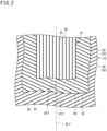
- FIG. 2 shows the configuration of the carcass 10 together with the band 14 described later.
- the right-left direction is the axial direction of the tire 2
- the up-down direction is the circumferential direction of the tire 2.
- the direction perpendicular to the surface of the sheet of FIG. 2 is the radial direction of the tire 2.
- the front side of the sheet of FIG. 2 is the outer side in the radial direction, and the back side thereof is the inner side in the radial direction.
- each carcass ply 24 included in the carcass 10 includes a large number of carcass cords 30 aligned with each other.
- each carcass cord 30 is represented by a solid line, but the carcass cords 30 are covered with a topping rubber 32.
- Each carcass cord 30 is tilted relative to the equator plane ELf. As shown in FIG. 2 , the direction in which each carcass cord 30 in the first carcass ply 26 is tilted is opposite to the direction in which each carcass cord 30 in the second carcass ply 28 is tilted.
- an angle indicated by reference character ⁇ 1f is the angle of each carcass cord 30 in the first carcass ply 26 with respect to the equator plane ELf.
- An angle indicated by reference character ⁇ 2f is the angle of each carcass cord 30 in the second carcass ply 28 with respect to the equator plane ELf.
- the tilt angle ⁇ 1f is equal to the tilt angle ⁇ 2f.
- the average value of the angle ⁇ 1f and the angle ⁇ 2f is used as an angle ⁇ f of the carcass cords 30 with respect to the equator plane ELf (hereinafter, also referred to as tilt angle ⁇ f of the carcass cords 30).
- a tilt angle ⁇ r of carcass cords of the rear tire, which will be described later, is also represented in the same manner as the tire 2.
- Each carcass cord 30 is a cord formed from an organic fiber.
- the organic fiber include nylon fibers, rayon fibers, polyester fibers, and aramid fibers.
- the inner liner 12 is located inward of the carcass 10.
- the inner liner 12 forms an inner surface of the tire 2.
- the inner liner 12 is formed from a crosslinked rubber that has a low gas permeability coefficient.
- the inner liner 12 maintains the internal pressure of the tire 2.
- the band 14 is located between the tread 4 and the carcass 10 in the radial direction. As shown in FIG. 1 , the band 14 is laminated on the carcass 10. A position indicated by reference character Bf is an end of the band 14. A length indicated by a double-headed arrow BWf is the width of the band 14. The width BWf of the band 14 is represented as the distance in the axial direction from a first end Bf of the band 14 to a second end Bf of the band 14. In the tire 2, the ratio (BWf/TWf) of the width BWf of the band 14 to the tread width TWf is not less than 0.80 and not greater than 0.95.
- the band 14 includes a spirally wound band cord 34.
- the band cord 34 is represented by a solid line, but the band cord 34 is covered with a topping rubber 36.
- the band cord 34 extends substantially in the circumferential direction. Specifically, the angle of the band cord 34 with respect to the circumferential direction is not greater than 5°.
- the band 14 is also referred to as jointless band.
- the band cord 34 is a steel cord or a cord formed from an organic fiber.
- the organic fiber include nylon fibers, rayon fibers, polyester fibers, and aramid fibers.
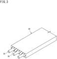
- a strip 38 in FIG. 3 is used for forming the band 14.
- the strip 38 has a tape shape.
- the strip 38 includes the band cord 34 and the topping rubber 36.
- the topping rubber 36 is in an unvulcanized state.
- the strip 38 includes a plurality of band cords 34 aligned with each other in the width direction thereof.
- the number of band cords 34 included in the strip 38 may be one.
- the band 14 is formed by spirally winding the strip 38 in the circumferential direction.
- the band 14 of the tire 2 includes one band ply.
- the number of cross-sections of the band cord 34 included per 5 cm width of a cross-section of the band 14 obtained in a zone having a width of 10 cm and centered on the equator plane ELf, in the meridional cross-section of the tire 2, is represented as a density Df of the band cord 34 in the band 14.
- the unit of the density Df of the band cord 34 is ends/5 cm.
- a density Dr of a band cord of the rear tire is also represented in the same manner as the tire 2.
- the density Df of the band cord 34 in the band 14 is preferably not less than 30 ends/5 cm. From the viewpoint of weight reduction, the density Df of the band cord 34 is preferably not greater than 50 ends/5 cm.
- FIG. 4 shows a part of a meridional cross-section of a rear tire 52 (hereinafter, tire 52).
- tire 52 the right-left direction is the axial direction of the tire 52
- the up-down direction is the radial direction of the tire 52.
- the direction perpendicular to the surface of the sheet of FIG. 4 is the circumferential direction of the tire 52.
- an alternate long and short dash line ELr represents the equator plane of the tire 52.
- a solid line BLr extending in the axial direction is a bead base line.
- the bead base line BLr is a line that defines the rim diameter (see JATMA or the like) of a rim (not shown) on which the tire 52 is mounted.
- the tire 52 includes a tread 54, a pair of sidewalls 56, a pair of beads 58, a carcass 60, an inner liner 62, and a band 64.
- the tread 54 is formed from a crosslinked rubber.
- the tread 54 comes into contact with a road surface at a tread surface 66 thereof.
- the tread surface 66 is curved such that a portion thereof at the equator plane ELr projects radially outward.
- a groove 68 is formed on the tread 54. Accordingly, a tread pattern is formed. The groove 68 does not have to be formed on the tread 54.
- a position indicated by reference character Re is an end of the tread surface 66.
- a length indicated by a double-headed arrow TWr is a tread width.
- each end Re of the tread surface 66 is an outer end in the axial direction of the tire 52.
- Each sidewall 56 is formed from a crosslinked rubber.
- the sidewall 56 is connected to an end of the tread 54.
- the sidewall 56 is located inward of the tread 54 in the radial direction.
- the sidewall 56 extends in the radial direction along the carcass 60.
- Each bead 58 is located inward of the sidewall 56 in the radial direction.
- the bead 58 includes a core 70 and an apex 72.
- the core 70 includes a steel wire which is not shown.
- the apex 72 is located outward of the core 70 in the radial direction.
- the apex 72 is tapered outward.
- the apex 72 is formed from a crosslinked rubber that has high stiffness.
- the carcass 60 is located inward of the tread 54 and the pair of sidewalls 56.
- the carcass 60 extends on and between a first bead 58 and a second bead 58.
- the above-described tread 54 is located outward of the carcass 60 in the radial direction.
- the carcass 60 includes at least one carcass ply 74.
- the carcass 60 of the tire 52 includes two carcass plies 74, that is, a first carcass ply 76 and a second carcass ply 78.
- the first carcass ply 76 includes a first ply body 76a which extends on and between a first core 70 and a second core 70, and a pair of first turned-up portions 76b which are connected to the first ply body 76a and turned up around the respective cores 70 from the inner side toward the outer side in the axial direction.
- the second carcass ply 78 includes a second ply body 78a which extends on and between the first core 70 and the second core 70, and a pair of second turned-up portions 78b which are connected to the second ply body 78a and turned up around the respective cores 70 from the inner side toward the outer side in the axial direction.
- a double-headed arrow HR1 indicates the height of the first turned-up portion 76b.
- a double-headed arrow HR2 indicates the height of the second turned-up portion 78b.
- the height HR1 of the first turned-up portion 76b is larger than the height HR2 of the second turned-up portion 78b.
- the height HR1 of the first turned-up portion 76b may be smaller than the height HR2 of the second turned-up portion 78b.
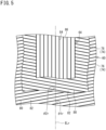
- FIG. 5 shows the configuration of the carcass 60 together with the band 64 described later.
- the right-left direction is the axial direction of the tire 52
- the up-down direction is the circumferential direction of the tire 52.
- the direction perpendicular to the surface of the sheet of FIG. 5 is the radial direction of the tire 52.
- the front side of the sheet of FIG. 5 is the outer side in the radial direction, and the back side thereof is the inner side in the radial direction.
- each carcass ply 74 includes a large number of carcass cords 80 aligned with each other.
- each carcass cord 80 is represented by a solid line, but the carcass cords 80 are covered with a topping rubber 82.
- Each carcass cord 80 is tilted relative to the equator plane ELr. As shown in FIG. 5 , the direction in which each carcass cord 80 in the first carcass ply 76 is tilted is opposite to the direction in which each carcass cord 80 in the second carcass ply 78 is tilted.
- an angle indicated by reference character ⁇ 1r is the angle of each carcass cord 80 in the first carcass ply 76 with respect to the equator plane ELr.
- An angle indicated by reference character ⁇ 2r is the angle of each carcass cord 80 in the second carcass ply 78 with respect to the equator plane ELr.
- the tilt angle ⁇ 1r is equal to the tilt angle ⁇ 2r.
- each carcass cord 80 is a cord formed from an organic fiber.
- the organic fiber include nylon fibers, rayon fibers, polyester fibers, and aramid fibers.
- the inner liner 62 is located inward of the carcass 60.
- the inner liner 62 forms an inner surface of the tire 52.
- the inner liner 62 is formed from a crosslinked rubber that has a low gas permeability coefficient. The inner liner 62 maintains the internal pressure of the tire 52.
- the band 64 is located between the tread 54 and the carcass 60 in the radial direction. As shown in FIG. 4 , the band 64 is laminated on the carcass 60. Similar to the band 14 of the front tire 2, the band 64 includes one band ply.
- a position indicated by reference character Br is an end of the band 64.
- a length indicated by a double-headed arrow BWr is the width of the band 64.
- the ratio (BWr/TWr) of the width BWr of the band 64 to the tread width TWr is not less than 0.80 and not greater than 0.95.
- the band 64 includes a spirally wound band cord 84.
- the band cord 84 is represented by a solid line, but the band cord 84 is covered with a topping rubber 86.
- the band cord 84 extends substantially in the circumferential direction. Specifically, the angle of the band cord 84 with respect to the circumferential direction is not greater than 5°.
- the band cord 84 is a steel cord or a cord formed from an organic fiber.
- the organic fiber include nylon fibers, rayon fibers, polyester fibers, and aramid fibers.
- a strip is used for forming the band 64, similar to the band 14 of the front tire 2.
- the band 64 is formed by spirally winding the strip in the circumferential direction.
- the density Dr of the band cord 84 in the band 64 is preferably not less than 30 ends/5 cm. From the viewpoint of weight reduction, the density Dr of the band cord 84 is preferably not greater than 50 ends/5 cm.
- the present inventor has conducted thorough studies for improving the ride comfort of a motorcycle, and as a result, the present inventor has found that a study focusing on the bending stiffness of a band cord is effective for improving the ride comfort, and the bending stiffness of the band cord also contributes to ensuring stability, and thus has completed the present invention.
- the bending stiffness of the band cord is the average value of a bending moment at +15 degrees and a bending moment at -15 degrees.
- the unit of the bending stiffness is g cm, and the bending stiffness is represented by a value rounded off to the second decimal place. If the bending stiffness of the band cord is too small to measure, the bending stiffness of the band cord is represented as 0.0 g ⁇ cm.
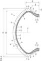
- the bending moment at +15 degrees and the bending moment at -15 degrees are obtained, for example, by using a stiffness tester (for example, 150-D type) manufactured by TABER INDUSTRIES (USA) as follows.
- both ends of the band cord (reference character B in FIG. 6 ) are attached to clamps (reference character K in FIG. 6 ).
- the bending moment when a bending angle of + 15 degrees is given is obtained as the bending moment at + 15 degrees
- the bending moment when a bending angle of -15 degrees is given is obtained as the bending moment at -15 degrees.
- a band cord having a low bending stiffness contributes to improvement of ride comfort. If the bending stiffness of the band cord is excessively low, when a high load is applied to the tire, the tire becomes significantly deformed. The tire having a large amount of deformation decreases stability.
- the rear wheel side of a vehicle body is heavier than the front wheel side of the vehicle body.
- lift acts, so that the rear wheel side becomes even heavier. Therefore, the band cord of the rear tire mounted on the rear wheel needs to have a bending stiffness having a certain value or higher.
- the present inventor has conducted thorough studies focusing on the fact that the contribution of the front tire is high for ride comfort and the contribution of the rear tire is high for stability, and as a result, the present inventor has found that ride comfort and stability are well-balanced in a tire pair that uses a band cord having a low bending stiffness for the front tire and that uses a band cord having a high bending stiffness for the rear tire, and has also found that when the ratio of the bending stiffness of the band cord of the front tire to the bending stiffness of the band cord of the rear tire is set to be not less than 0.7, the ride comfort is decreased due to the front tire and the stability is decreased due to the rear tire.
- the ratio (Jf/Jr) of a bending stiffness Jf of the band cord 34 of the front tire 2 to a bending stiffness Jr of the band cord 84 of the rear tire 52 is not less than 0.0 and less than 0.7.
- the front tire 2 contributes to improving ride comfort
- the rear tire 52 contributes to ensuring stability.
- good ride comfort and stability are achieved.
- the bending stiffness Jf of the band cord 34 of the front tire 2 is less than 15.0 g cm
- the bending stiffness Jr of the band cord 84 of the rear tire 52 is not less than 15.0 g ⁇ cm and not greater than 40.0 g ⁇ cm.
- the bending stiffness Jf of the band cord 34 of the front tire 2 is set to be less than 15.0 g cm, a decrease in ride comfort due to the front tire 2 is suppressed.
- the bending stiffness Jf is more preferably not greater than 10.0 g cm. From the viewpoint of ride comfort, it is more preferable that the bending stiffness Jf is lower, so that a preferable lower limit of the bending stiffness Jf is not set.
- the bending stiffness Jr of the band cord 84 of the rear tire 52 is set to be not less than 15.0 g cm, a decrease in stability due to the rear tire 52 is suppressed.
- the bending stiffness Jr is set to be not greater than 40.0 g cm, a decrease in ride comfort due to the rear tire 52 is suppressed. From this viewpoint, the bending stiffness Jr is more preferably not greater than 30 g ⁇ cm.
- the bending stiffness Jf of the band cord 34 of the front tire 2 is not greater than 10.0 g cm, and the bending stiffness Jr of the band cord 84 of the rear tire 52 is not less than 15.0 g ⁇ cm and not greater than 30.0 g ⁇ cm.
- the band cord 34 of the front tire 2 is a steel cord or a cord formed from an organic fiber. Since the band cord 34 is formed so as to have the low bending stiffness Jf, when a steel cord is used as the band cord 34, a steel cord having a small diameter is used. In this case, the strength of the band cord 34 is reduced, so that there is a possibility that the water pressure resistance fracture strength cannot meet a predetermined standard.
- a cord formed from an organic fiber other than an aramid fiber, as a cord formed from an organic fiber is used as the band cord 34, the holding force by the band 14 may be insufficient, and the high-speed stability may be decreased.
- the band cord 34 of the front tire 2 in the tire pair is preferably a cord formed from an aramid fiber.
- the band cord 84 of the rear tire 52 is a steel cord or a cord formed from an organic fiber. Since the band cord 84 has the high bending stiffness Jr, when a cord formed from an organic fiber is used as the band cord 84, a cord formed from an organic fiber and having a large diameter is used. In this case, the proportion of the band cord 84 in the band 64 is increased, and the amount of the topping rubber 86 covering the band cord 84 is decreased. When the band cord 84 cannot be covered with a sufficient amount of the topping rubber 86, the topping rubber 86 is likely to be peeled from the band cord 84, and the durability of the rear tire 52 may be decreased. From the viewpoint of preventing a decrease in durability due to the band 64, the band cord 84 of the rear tire 52 in the tire pair is preferably a steel cord.
- the band cord 34 having the low bending stiffness Jf is used for the band 14 of the front tire 2, so that the stress when a slip angle is given to the front tire 2 is decreased. Depending on the degree of stress decrease, the cornering performance may be impaired.
- the tilt angle ⁇ f of the carcass cords 30 of the front tire 2 is smaller than the tilt angle ⁇ r of the carcass cords 80 of the rear tire 52.
- the small tilt angle ⁇ f increases the stress when a slip angle is given to the front tire 2, so that the cornering force of the front tire 2 is made larger than the cornering force of the rear tire 52.
- the cornering performance of the motorcycle is improved even though the band cord 34 having the low bending stiffness Jf is used for the band 14 of the front tire 2 in the tire pair.
- the tilt angle ⁇ f of the carcass cords 30 of the front tire 2 is preferably smaller than the tilt angle ⁇ r of the carcass cords 80 of the rear tire 52.
- the difference ( ⁇ r- ⁇ f) between the tilt angle ⁇ r of the carcass cords 80 of the rear tire 52 and the tilt angle ⁇ f of the carcass cords 30 of the front tire 2 is preferably not less than 5° and more preferably not less than 8°.
- the difference ( ⁇ r- ⁇ f) is preferably not greater than 25° and more preferably not greater than 20°.
- the tilt angle ⁇ f of the carcass cords 30 of the front tire 2 is not less than 20° and less than 70°, and the tilt angle ⁇ r of the carcass cords 80 of the rear tire 52 is not less than 70°.
- the tilt angle ⁇ f is set to be not less than 20°, the stiffness of the carcass 10 in the front tire 2 is appropriately maintained, so that good ride comfort is maintained. From this viewpoint, the tilt angle ⁇ f is more preferably not less than 30° and further preferably not less than 40°. When the tilt angle Of is set to be less than 70°, the carcass 10 contributes to improvement of the cornering performance. From this viewpoint, the tilt angle ⁇ f is more preferably not greater than 68° and further preferably not greater than 65°.
- the tilt angle ⁇ r is set to be not less than 70°, the stiffness of the carcass 60 in the rear tire 52 is appropriately maintained.
- the contribution of the rear tire 52 to the cornering performance and the contribution of the front tire 2 to the cornering performance are well-balanced, so that good lightness is maintained in the motorcycle.
- the tire pair can effectively contribute to improvement of the cornering performance.
- the tilt angle ⁇ r is more preferably not less than 72° and further preferably not less than 80°.
- the upper limit of the tilt angle ⁇ r is 90°.
- the density of the band cord in the band affects the stress when a slip angle is given to the tire.
- Great stress contributes to improvement of the cornering force of the tire.
- the density Df of the band cord 34 in the band 14 of the front tire 2 is higher than the density Dr of the band cord 84 in the band 64 of the rear tire 52. Therefore, the cornering force of the front tire 2 is made larger than the cornering force of the rear tire 52. The cornering performance of the motorcycle is improved even though the band cord 34 having the low bending stiffness Jf is used for the band 14 of the front tire 2 in the tire pair. From this viewpoint, the density Df of the band cord 34 in the band 14 of the front tire 2 is preferably higher than the density Dr of the band cord 84 in the band 64 of the rear tire 52.
- the ratio (Df/Dr) of the density Df of the band cord 34 in the band 14 of the front tire 2 to the density Dr of the band cord 84 in the band 64 of the rear tire 52 is preferably not less than 1.1 and more preferably not less than 1.2. From the viewpoint of well-balancing the stiffness of the front tire 2 and the stiffness of the rear tire 52, the ratio (Df/Dr) is preferably not greater than 1.4 and more preferably not greater than 1.3.
- a motorcycle tire pair that can contribute to improving ride comfort and ensuring stability is obtained.
- Example 1 a cord formed from an aramid fiber was used as the band cord. This is represented as "K" in the cell for band cord under F in Table 1.
- the bending stiffness Jf and the density Df of the band cord and the tilt angle ⁇ f of the carcass cords are as shown in Table 1 below.
- each carcass cord In the front tire, a cord formed from a rayon fiber was used as each carcass cord.
- the configuration of the carcass cord was 1840 dtex/2.
- the height HF1 of each first turned-up portion was 45 mm, and the height HF2 of each second turned-up portion was 20 mm.
- each carcass cord In the rear tire, a cord formed from a rayon fiber was used as each carcass cord.
- the configuration of the carcass cord was 1840 dtex/2.
- the height HR1 of each first turned-up portion was 50 mm, and the height HR2 of each second turned-up portion was 30 mm.
- Example 2 A tire pair of Example 2 was obtained in the same manner as Example 1, except that the tilt angle ⁇ r of the carcass cords of the rear tire is as shown in Table 1 below.
- Example 3 A tire pair of Example 3 was obtained in the same manner as Example 2, except that the tilt angle ⁇ f of the carcass cords of the front tire is as shown in Table 1 below.
- Example 4 A tire pair of Example 4 was obtained in the same manner as Example 3, except that the density Df of the band cord of the front tire is as shown in Table 1 below.
- Tire pairs of Examples 5 to 10 and Comparative Examples 1 to 3 were obtained in the same manner as Example 1, except that the specifications of the band cord of the front tire and the specifications of the band cord of the rear tire are as shown in Tables 1 and 2 below.
- a front tire was fitted onto a rim (MT 3.50 ⁇ 17) and inflated with air to adjust the internal pressure of the tire to 250 kPa.
- a rear tire was fitted onto a rim (MT 5.50 ⁇ 17) and inflated with air to adjust the internal pressure of the tire to 290 kPa.
- the motorcycle was caused to run on a test course having a dry asphalt road surface, and sensory evaluations (5-point method) were made by a test rider for ride comfort, stability, and cornering performance.
- the results are shown as indexes in Tables 1 and 2 below.
- the total value of the indexes of the respective items is described in each cell for steering stability in Tables 1 and 2. A higher value indicates a better result.
- test tire (rear tire) was caused to run on a drum tester under the following conditions. The broken state of each cord and the peeled state of each member after running were visually confirmed. The results are shown as indexes in Tables 1 and 2 below. A higher value indicates that the tire has better durability.
Landscapes
- Engineering & Computer Science (AREA)
- Mechanical Engineering (AREA)
- Tires In General (AREA)
Claims (6)
- Motorradreifenpaar, das einen Vorderreifen (2) und einen Hinterreifen (52) umfasst, wobeisowohl der Vorderreifen (2) als auch der Hinterreifen (52) ein Paar Wülste (8, 58), eine Karkasse (10, 60), die sich auf und zwischen einem ersten Wulst (8, 58) und einem zweiten Wulst (8, 58) erstreckt, eine Lauffläche (4, 54), die in einer radialen Richtung außerhalb der Karkasse (10, 60) angeordnet ist, und ein Band (14, 64) aufweist, das in der radialen Richtung zwischen der Lauffläche (4, 54) und der Karkasse (10, 60) angeordnet ist,die Karkasse (10, 60) eine große Anzahl von Karkasskorden (30, 80) umfasst, die zueinander ausgerichtet und jeweils relativ zu einer Äquatorebene geneigt sind, unddas Band (14, 64) einen Bandkord (34, 84) aufweist, der sich im Wesentlichen in einer Umfangsrichtung erstreckt,dadurch gekennzeichnet, dassein Verhältnis (Jf/Jr) einer Biegesteifigkeit (Jf) des Bandkords (34) des Vorderreifens (2) zu einer Biegesteifigkeit (Jr) des Bandkords (84) des Hinterreifens (52) nicht kleiner als 0,0 und kleiner als 0,7 ist.
- Motorradreifenpaar (1) nach Anspruch 1, wobeidie Biegesteifigkeit (Jf) des Bandkords (34) des Vorderreifens (2) weniger als 15,0 g•cm beträgt, unddie Biegesteifigkeit (Jr) des Bandkords (84) des Hinterreifens (52) nicht weniger als 15,0 g•cm und nicht mehr als 40,0 g•cm beträgt.
- Motorradreifenpaar nach Anspruch 1 oder 2, wobeider Bandkord (34) des Vorderreifens (2) ein aus einer Aramidfaser gebildeter Kord ist, undder Bandkord (84) des Hinterreifens (52) ein Stahlkord ist.
- Motorradreifenpaar nach einem der Ansprüche 1 bis 3, wobei ein Winkel (θf) der Karkasskorde (30) des Vorderreifens (2) in Bezug auf die Äquatorebene kleiner ist als ein Winkel (θr) der Karkasskorde (80) des Hinterreifens (52) in Bezug auf die Äquatorebene.
- Motorradreifenpaar (1) nach Anspruch 4, wobeider Winkel (θf) der Karkasskorde (30) des Vorderreifens (2) in Bezug auf die Äquatorebene nicht weniger als 20° und weniger als 70° beträgt, undder Winkel (θr) der Karkasskorde (80) des Hinterreifens (52) gegenüber der Äquatorebene nicht weniger als 70° beträgt.
- Motorradreifenpaar nach einem der Ansprüche 1 bis 5, wobei eine Dichte (Df) des Bandkords (34) in dem Band (14) des Vorderreifens (2) höher ist als eine Dichte (Dr) des Bandkords (84) in dem Band (64) des Hinterreifens (52).
Applications Claiming Priority (1)
| Application Number | Priority Date | Filing Date | Title |
|---|---|---|---|
| JP2021024276A JP7608861B2 (ja) | 2021-02-18 | 2021-02-18 | 二輪自動車用タイヤ対 |
Publications (2)
| Publication Number | Publication Date |
|---|---|
| EP4046824A1 EP4046824A1 (de) | 2022-08-24 |
| EP4046824B1 true EP4046824B1 (de) | 2023-08-23 |
Family
ID=80034917
Family Applications (1)
| Application Number | Title | Priority Date | Filing Date |
|---|---|---|---|
| EP22153385.4A Active EP4046824B1 (de) | 2021-02-18 | 2022-01-26 | Motorradreifenpaar |
Country Status (4)
| Country | Link |
|---|---|
| US (1) | US11760131B2 (de) |
| EP (1) | EP4046824B1 (de) |
| JP (1) | JP7608861B2 (de) |
| CN (1) | CN114953851B (de) |
Family Cites Families (18)
| Publication number | Priority date | Publication date | Assignee | Title |
|---|---|---|---|---|
| JPS5973307A (ja) | 1982-10-18 | 1984-04-25 | Bridgestone Corp | 二輪車用空気入りベルテツドタイヤ対 |
| JP2567836B2 (ja) | 1985-11-13 | 1996-12-25 | 株式会社ブリヂストン | 二輪車用ラジアルタイヤ |
| JPH0655561B2 (ja) | 1988-03-18 | 1994-07-27 | 株式会社ブリヂストン | 二輪車用タイヤ組立体 |
| JPH0325005A (ja) * | 1989-06-21 | 1991-02-01 | Bridgestone Corp | 二輪車用空気入りタイヤ対 |
| JPH08295102A (ja) * | 1995-04-26 | 1996-11-12 | Sumitomo Rubber Ind Ltd | 空気入りラジアルタイヤ |
| IT1283051B1 (it) * | 1996-05-22 | 1998-04-07 | Pirelli | Coppia di pneumatici ad elevata curvatura trasversale,particolarmente per veicoli a due ruote e metodo per il controllo del comportamento |
| ES2323455T3 (es) * | 2002-05-24 | 2009-07-16 | Bridgestone Corporation | Neumatico radial para motocicleta. |
| DE602005025081D1 (de) | 2004-01-26 | 2011-01-13 | Bridgestone Corp | Radialluftreifen für motorrad |
| JP2008143327A (ja) | 2006-12-08 | 2008-06-26 | Sumitomo Rubber Ind Ltd | 自動二輪車用タイヤ |
| JP5138923B2 (ja) | 2006-12-11 | 2013-02-06 | 住友ゴム工業株式会社 | 自動二輪車用タイヤ |
| JP2008254623A (ja) | 2007-04-06 | 2008-10-23 | Sumitomo Rubber Ind Ltd | 自動二輪車用ラジアルタイヤ |
| JP5350749B2 (ja) * | 2008-10-28 | 2013-11-27 | 住友ゴム工業株式会社 | 二輪自動車用タイヤ対 |
| JP2014172547A (ja) * | 2013-03-11 | 2014-09-22 | Sumitomo Rubber Ind Ltd | 自動二輪車用ラジアルタイヤ |
| JP5753554B2 (ja) * | 2013-07-29 | 2015-07-22 | 株式会社ブリヂストン | 自動二輪車用タイヤ |
| JP6230959B2 (ja) * | 2014-05-30 | 2017-11-15 | 東洋ゴム工業株式会社 | ランフラットタイヤ |
| JP7014580B2 (ja) * | 2017-11-29 | 2022-02-01 | Toyo Tire株式会社 | 空気入りタイヤ |
| JP7226061B2 (ja) | 2019-04-22 | 2023-02-21 | 住友ゴム工業株式会社 | 自動二輪車用タイヤ及び自動二輪車用タイヤセット |
| JP7490473B2 (ja) | 2019-08-02 | 2024-05-27 | キヤノン株式会社 | 液体吐出ヘッドの製造方法及び液体吐出ヘッド |
-
2021
- 2021-02-18 JP JP2021024276A patent/JP7608861B2/ja active Active
-
2022
- 2022-01-18 US US17/577,636 patent/US11760131B2/en active Active
- 2022-01-24 CN CN202210078433.3A patent/CN114953851B/zh active Active
- 2022-01-26 EP EP22153385.4A patent/EP4046824B1/de active Active
Also Published As
| Publication number | Publication date |
|---|---|
| CN114953851B (zh) | 2025-08-22 |
| CN114953851A (zh) | 2022-08-30 |
| JP7608861B2 (ja) | 2025-01-07 |
| US11760131B2 (en) | 2023-09-19 |
| US20220258538A1 (en) | 2022-08-18 |
| EP4046824A1 (de) | 2022-08-24 |
| JP2022126287A (ja) | 2022-08-30 |
Similar Documents
| Publication | Publication Date | Title |
|---|---|---|
| EP2610075A1 (de) | Zweirädriger Autoreifen | |
| EP2899042B1 (de) | Motorradreifen | |
| US20180257439A1 (en) | Pneumatic Tire | |
| EP2815895B1 (de) | Luftreifen für ein zweirädriges kraftfahrzeug | |
| EP2196328A1 (de) | Reifenpaar für kraftfahrzeug mit zwei rädern | |
| EP3530485B2 (de) | Luftreifen | |
| EP3202599B1 (de) | Luftreifen | |
| EP3789216B1 (de) | Luftreifen | |
| EP3388253B1 (de) | Reifen für ein zweirädriges automobiles fahrzeug | |
| EP2602125B1 (de) | Luftreifen | |
| EP3838624B1 (de) | Luftreifen | |
| EP3943660B1 (de) | Reifen | |
| EP4046824B1 (de) | Motorradreifenpaar | |
| EP3287302B1 (de) | Luftreifen | |
| EP4059739A1 (de) | Reifen für gokarts | |
| JPH0649105U (ja) | 空気入りラジアルタイヤ | |
| JPH1178411A (ja) | 乗用車用空気入りラジアル・タイヤ | |
| EP3730313B1 (de) | Motorradreifen | |
| EP1642752B1 (de) | Radialer Motorradluftreifen | |
| US20230339267A1 (en) | Pneumatic tire | |
| EP4223558B1 (de) | Motorradreifenpaar | |
| EP3398792B1 (de) | Reifen für ein zweirädriges automobiles fahrzeug | |
| EP3932695A1 (de) | Motorradreifen | |
| EP4253089B1 (de) | Motorradreifenpaar | |
| EP3290231B1 (de) | Reifen für zweirädriges fahrzeug |
Legal Events
| Date | Code | Title | Description |
|---|---|---|---|
| PUAI | Public reference made under article 153(3) epc to a published international application that has entered the european phase |
Free format text: ORIGINAL CODE: 0009012 |
|
| STAA | Information on the status of an ep patent application or granted ep patent |
Free format text: STATUS: THE APPLICATION HAS BEEN PUBLISHED |
|
| AK | Designated contracting states |
Kind code of ref document: A1 Designated state(s): AL AT BE BG CH CY CZ DE DK EE ES FI FR GB GR HR HU IE IS IT LI LT LU LV MC MK MT NL NO PL PT RO RS SE SI SK SM TR |
|
| STAA | Information on the status of an ep patent application or granted ep patent |
Free format text: STATUS: REQUEST FOR EXAMINATION WAS MADE |
|
| 17P | Request for examination filed |
Effective date: 20221018 |
|
| RBV | Designated contracting states (corrected) |
Designated state(s): AL AT BE BG CH CY CZ DE DK EE ES FI FR GB GR HR HU IE IS IT LI LT LU LV MC MK MT NL NO PL PT RO RS SE SI SK SM TR |
|
| GRAP | Despatch of communication of intention to grant a patent |
Free format text: ORIGINAL CODE: EPIDOSNIGR1 |
|
| STAA | Information on the status of an ep patent application or granted ep patent |
Free format text: STATUS: GRANT OF PATENT IS INTENDED |
|
| P01 | Opt-out of the competence of the unified patent court (upc) registered |
Effective date: 20230510 |
|
| INTG | Intention to grant announced |
Effective date: 20230614 |
|
| GRAS | Grant fee paid |
Free format text: ORIGINAL CODE: EPIDOSNIGR3 |
|
| GRAA | (expected) grant |
Free format text: ORIGINAL CODE: 0009210 |
|
| STAA | Information on the status of an ep patent application or granted ep patent |
Free format text: STATUS: THE PATENT HAS BEEN GRANTED |
|
| AK | Designated contracting states |
Kind code of ref document: B1 Designated state(s): AL AT BE BG CH CY CZ DE DK EE ES FI FR GB GR HR HU IE IS IT LI LT LU LV MC MK MT NL NO PL PT RO RS SE SI SK SM TR |
|
| REG | Reference to a national code |
Ref country code: GB Ref legal event code: FG4D |
|
| REG | Reference to a national code |
Ref country code: CH Ref legal event code: EP |
|
| REG | Reference to a national code |
Ref country code: IE Ref legal event code: FG4D |
|
| REG | Reference to a national code |
Ref country code: DE Ref legal event code: R096 Ref document number: 602022000352 Country of ref document: DE |
|
| REG | Reference to a national code |
Ref country code: LT Ref legal event code: MG9D |
|
| REG | Reference to a national code |
Ref country code: NL Ref legal event code: MP Effective date: 20230823 |
|
| REG | Reference to a national code |
Ref country code: AT Ref legal event code: MK05 Ref document number: 1602165 Country of ref document: AT Kind code of ref document: T Effective date: 20230823 |
|
| PG25 | Lapsed in a contracting state [announced via postgrant information from national office to epo] |
Ref country code: GR Free format text: LAPSE BECAUSE OF FAILURE TO SUBMIT A TRANSLATION OF THE DESCRIPTION OR TO PAY THE FEE WITHIN THE PRESCRIBED TIME-LIMIT Effective date: 20231124 |
|
| PG25 | Lapsed in a contracting state [announced via postgrant information from national office to epo] |
Ref country code: IS Free format text: LAPSE BECAUSE OF FAILURE TO SUBMIT A TRANSLATION OF THE DESCRIPTION OR TO PAY THE FEE WITHIN THE PRESCRIBED TIME-LIMIT Effective date: 20231223 |
|
| PG25 | Lapsed in a contracting state [announced via postgrant information from national office to epo] |
Ref country code: SE Free format text: LAPSE BECAUSE OF FAILURE TO SUBMIT A TRANSLATION OF THE DESCRIPTION OR TO PAY THE FEE WITHIN THE PRESCRIBED TIME-LIMIT Effective date: 20230823 Ref country code: RS Free format text: LAPSE BECAUSE OF FAILURE TO SUBMIT A TRANSLATION OF THE DESCRIPTION OR TO PAY THE FEE WITHIN THE PRESCRIBED TIME-LIMIT Effective date: 20230823 Ref country code: PT Free format text: LAPSE BECAUSE OF FAILURE TO SUBMIT A TRANSLATION OF THE DESCRIPTION OR TO PAY THE FEE WITHIN THE PRESCRIBED TIME-LIMIT Effective date: 20231226 Ref country code: NO Free format text: LAPSE BECAUSE OF FAILURE TO SUBMIT A TRANSLATION OF THE DESCRIPTION OR TO PAY THE FEE WITHIN THE PRESCRIBED TIME-LIMIT Effective date: 20231123 Ref country code: NL Free format text: LAPSE BECAUSE OF FAILURE TO SUBMIT A TRANSLATION OF THE DESCRIPTION OR TO PAY THE FEE WITHIN THE PRESCRIBED TIME-LIMIT Effective date: 20230823 Ref country code: LV Free format text: LAPSE BECAUSE OF FAILURE TO SUBMIT A TRANSLATION OF THE DESCRIPTION OR TO PAY THE FEE WITHIN THE PRESCRIBED TIME-LIMIT Effective date: 20230823 Ref country code: LT Free format text: LAPSE BECAUSE OF FAILURE TO SUBMIT A TRANSLATION OF THE DESCRIPTION OR TO PAY THE FEE WITHIN THE PRESCRIBED TIME-LIMIT Effective date: 20230823 Ref country code: IS Free format text: LAPSE BECAUSE OF FAILURE TO SUBMIT A TRANSLATION OF THE DESCRIPTION OR TO PAY THE FEE WITHIN THE PRESCRIBED TIME-LIMIT Effective date: 20231223 Ref country code: HR Free format text: LAPSE BECAUSE OF FAILURE TO SUBMIT A TRANSLATION OF THE DESCRIPTION OR TO PAY THE FEE WITHIN THE PRESCRIBED TIME-LIMIT Effective date: 20230823 Ref country code: GR Free format text: LAPSE BECAUSE OF FAILURE TO SUBMIT A TRANSLATION OF THE DESCRIPTION OR TO PAY THE FEE WITHIN THE PRESCRIBED TIME-LIMIT Effective date: 20231124 Ref country code: FI Free format text: LAPSE BECAUSE OF FAILURE TO SUBMIT A TRANSLATION OF THE DESCRIPTION OR TO PAY THE FEE WITHIN THE PRESCRIBED TIME-LIMIT Effective date: 20230823 Ref country code: AT Free format text: LAPSE BECAUSE OF FAILURE TO SUBMIT A TRANSLATION OF THE DESCRIPTION OR TO PAY THE FEE WITHIN THE PRESCRIBED TIME-LIMIT Effective date: 20230823 |
|
| PG25 | Lapsed in a contracting state [announced via postgrant information from national office to epo] |
Ref country code: PL Free format text: LAPSE BECAUSE OF FAILURE TO SUBMIT A TRANSLATION OF THE DESCRIPTION OR TO PAY THE FEE WITHIN THE PRESCRIBED TIME-LIMIT Effective date: 20230823 |
|
| PG25 | Lapsed in a contracting state [announced via postgrant information from national office to epo] |
Ref country code: ES Free format text: LAPSE BECAUSE OF FAILURE TO SUBMIT A TRANSLATION OF THE DESCRIPTION OR TO PAY THE FEE WITHIN THE PRESCRIBED TIME-LIMIT Effective date: 20230823 |
|
| PG25 | Lapsed in a contracting state [announced via postgrant information from national office to epo] |
Ref country code: SM Free format text: LAPSE BECAUSE OF FAILURE TO SUBMIT A TRANSLATION OF THE DESCRIPTION OR TO PAY THE FEE WITHIN THE PRESCRIBED TIME-LIMIT Effective date: 20230823 Ref country code: RO Free format text: LAPSE BECAUSE OF FAILURE TO SUBMIT A TRANSLATION OF THE DESCRIPTION OR TO PAY THE FEE WITHIN THE PRESCRIBED TIME-LIMIT Effective date: 20230823 Ref country code: ES Free format text: LAPSE BECAUSE OF FAILURE TO SUBMIT A TRANSLATION OF THE DESCRIPTION OR TO PAY THE FEE WITHIN THE PRESCRIBED TIME-LIMIT Effective date: 20230823 Ref country code: EE Free format text: LAPSE BECAUSE OF FAILURE TO SUBMIT A TRANSLATION OF THE DESCRIPTION OR TO PAY THE FEE WITHIN THE PRESCRIBED TIME-LIMIT Effective date: 20230823 Ref country code: DK Free format text: LAPSE BECAUSE OF FAILURE TO SUBMIT A TRANSLATION OF THE DESCRIPTION OR TO PAY THE FEE WITHIN THE PRESCRIBED TIME-LIMIT Effective date: 20230823 Ref country code: CZ Free format text: LAPSE BECAUSE OF FAILURE TO SUBMIT A TRANSLATION OF THE DESCRIPTION OR TO PAY THE FEE WITHIN THE PRESCRIBED TIME-LIMIT Effective date: 20230823 Ref country code: SK Free format text: LAPSE BECAUSE OF FAILURE TO SUBMIT A TRANSLATION OF THE DESCRIPTION OR TO PAY THE FEE WITHIN THE PRESCRIBED TIME-LIMIT Effective date: 20230823 |
|
| REG | Reference to a national code |
Ref country code: DE Ref legal event code: R097 Ref document number: 602022000352 Country of ref document: DE |
|
| PG25 | Lapsed in a contracting state [announced via postgrant information from national office to epo] |
Ref country code: IT Free format text: LAPSE BECAUSE OF FAILURE TO SUBMIT A TRANSLATION OF THE DESCRIPTION OR TO PAY THE FEE WITHIN THE PRESCRIBED TIME-LIMIT Effective date: 20230823 |
|
| PLBE | No opposition filed within time limit |
Free format text: ORIGINAL CODE: 0009261 |
|
| STAA | Information on the status of an ep patent application or granted ep patent |
Free format text: STATUS: NO OPPOSITION FILED WITHIN TIME LIMIT |
|
| 26N | No opposition filed |
Effective date: 20240524 |
|
| PG25 | Lapsed in a contracting state [announced via postgrant information from national office to epo] |
Ref country code: SI Free format text: LAPSE BECAUSE OF FAILURE TO SUBMIT A TRANSLATION OF THE DESCRIPTION OR TO PAY THE FEE WITHIN THE PRESCRIBED TIME-LIMIT Effective date: 20230823 |
|
| PG25 | Lapsed in a contracting state [announced via postgrant information from national office to epo] |
Ref country code: MC Free format text: LAPSE BECAUSE OF FAILURE TO SUBMIT A TRANSLATION OF THE DESCRIPTION OR TO PAY THE FEE WITHIN THE PRESCRIBED TIME-LIMIT Effective date: 20230823 |
|
| PG25 | Lapsed in a contracting state [announced via postgrant information from national office to epo] |
Ref country code: MC Free format text: LAPSE BECAUSE OF FAILURE TO SUBMIT A TRANSLATION OF THE DESCRIPTION OR TO PAY THE FEE WITHIN THE PRESCRIBED TIME-LIMIT Effective date: 20230823 |
|
| PG25 | Lapsed in a contracting state [announced via postgrant information from national office to epo] |
Ref country code: LU Free format text: LAPSE BECAUSE OF NON-PAYMENT OF DUE FEES Effective date: 20240126 |
|
| PG25 | Lapsed in a contracting state [announced via postgrant information from national office to epo] |
Ref country code: LU Free format text: LAPSE BECAUSE OF NON-PAYMENT OF DUE FEES Effective date: 20240126 |
|
| PG25 | Lapsed in a contracting state [announced via postgrant information from national office to epo] |
Ref country code: BE Free format text: LAPSE BECAUSE OF NON-PAYMENT OF DUE FEES Effective date: 20240131 |
|
| PG25 | Lapsed in a contracting state [announced via postgrant information from national office to epo] |
Ref country code: BE Free format text: LAPSE BECAUSE OF NON-PAYMENT OF DUE FEES Effective date: 20240131 |
|
| REG | Reference to a national code |
Ref country code: BE Ref legal event code: MM Effective date: 20240131 |
|
| PG25 | Lapsed in a contracting state [announced via postgrant information from national office to epo] |
Ref country code: BG Free format text: LAPSE BECAUSE OF FAILURE TO SUBMIT A TRANSLATION OF THE DESCRIPTION OR TO PAY THE FEE WITHIN THE PRESCRIBED TIME-LIMIT Effective date: 20230823 |
|
| PG25 | Lapsed in a contracting state [announced via postgrant information from national office to epo] |
Ref country code: BG Free format text: LAPSE BECAUSE OF FAILURE TO SUBMIT A TRANSLATION OF THE DESCRIPTION OR TO PAY THE FEE WITHIN THE PRESCRIBED TIME-LIMIT Effective date: 20230823 |
|
| PG25 | Lapsed in a contracting state [announced via postgrant information from national office to epo] |
Ref country code: IE Free format text: LAPSE BECAUSE OF NON-PAYMENT OF DUE FEES Effective date: 20240126 |
|
| PG25 | Lapsed in a contracting state [announced via postgrant information from national office to epo] |
Ref country code: IE Free format text: LAPSE BECAUSE OF NON-PAYMENT OF DUE FEES Effective date: 20240126 |
|
| PG25 | Lapsed in a contracting state [announced via postgrant information from national office to epo] |
Ref country code: CY Free format text: LAPSE BECAUSE OF FAILURE TO SUBMIT A TRANSLATION OF THE DESCRIPTION OR TO PAY THE FEE WITHIN THE PRESCRIBED TIME-LIMIT; INVALID AB INITIO Effective date: 20220126 |
|
| REG | Reference to a national code |
Ref country code: CH Ref legal event code: PL |
|
| PG25 | Lapsed in a contracting state [announced via postgrant information from national office to epo] |
Ref country code: CH Free format text: LAPSE BECAUSE OF NON-PAYMENT OF DUE FEES Effective date: 20250131 |
|
| PG25 | Lapsed in a contracting state [announced via postgrant information from national office to epo] |
Ref country code: TR Free format text: LAPSE BECAUSE OF FAILURE TO SUBMIT A TRANSLATION OF THE DESCRIPTION OR TO PAY THE FEE WITHIN THE PRESCRIBED TIME-LIMIT Effective date: 20230823 |
|
| PGFP | Annual fee paid to national office [announced via postgrant information from national office to epo] |
Ref country code: FR Payment date: 20251128 Year of fee payment: 5 |
|
| PGFP | Annual fee paid to national office [announced via postgrant information from national office to epo] |
Ref country code: DE Payment date: 20251203 Year of fee payment: 5 |