EP4045447B1 - Verfahren und vorrichtung zur korrektur der vorschubstrecke eines bandes zum schneiden - Google Patents
Verfahren und vorrichtung zur korrektur der vorschubstrecke eines bandes zum schneiden Download PDFInfo
- Publication number
- EP4045447B1 EP4045447B1 EP20775021.7A EP20775021A EP4045447B1 EP 4045447 B1 EP4045447 B1 EP 4045447B1 EP 20775021 A EP20775021 A EP 20775021A EP 4045447 B1 EP4045447 B1 EP 4045447B1
- Authority
- EP
- European Patent Office
- Prior art keywords
- distance
- feeding
- strip
- longitudinal edge
- cutting
- Prior art date
- Legal status (The legal status is an assumption and is not a legal conclusion. Google has not performed a legal analysis and makes no representation as to the accuracy of the status listed.)
- Active
Links
Images


Classifications
-
- B—PERFORMING OPERATIONS; TRANSPORTING
- B26—HAND CUTTING TOOLS; CUTTING; SEVERING
- B26D—CUTTING; DETAILS COMMON TO MACHINES FOR PERFORATING, PUNCHING, CUTTING-OUT, STAMPING-OUT OR SEVERING
- B26D5/00—Arrangements for operating and controlling machines or devices for cutting, cutting-out, stamping-out, punching, perforating, or severing by means other than cutting
- B26D5/007—Control means comprising cameras, vision or image processing systems
-
- B—PERFORMING OPERATIONS; TRANSPORTING
- B65—CONVEYING; PACKING; STORING; HANDLING THIN OR FILAMENTARY MATERIAL
- B65H—HANDLING THIN OR FILAMENTARY MATERIAL, e.g. SHEETS, WEBS, CABLES
- B65H35/00—Delivering articles from cutting or line-perforating machines; Article or web delivery apparatus incorporating cutting or line-perforating devices, e.g. adhesive tape dispensers
- B65H35/04—Delivering articles from cutting or line-perforating machines; Article or web delivery apparatus incorporating cutting or line-perforating devices, e.g. adhesive tape dispensers from or with transverse cutters or perforators
- B65H35/06—Delivering articles from cutting or line-perforating machines; Article or web delivery apparatus incorporating cutting or line-perforating devices, e.g. adhesive tape dispensers from or with transverse cutters or perforators from or with blade, e.g. shear-blade, cutters or perforators
-
- B—PERFORMING OPERATIONS; TRANSPORTING
- B65—CONVEYING; PACKING; STORING; HANDLING THIN OR FILAMENTARY MATERIAL
- B65H—HANDLING THIN OR FILAMENTARY MATERIAL, e.g. SHEETS, WEBS, CABLES
- B65H35/00—Delivering articles from cutting or line-perforating machines; Article or web delivery apparatus incorporating cutting or line-perforating devices, e.g. adhesive tape dispensers
- B65H35/0006—Article or web delivery apparatus incorporating cutting or line-perforating devices
- B65H35/006—Article or web delivery apparatus incorporating cutting or line-perforating devices with means for delivering a predetermined length of tape
-
- B—PERFORMING OPERATIONS; TRANSPORTING
- B26—HAND CUTTING TOOLS; CUTTING; SEVERING
- B26D—CUTTING; DETAILS COMMON TO MACHINES FOR PERFORATING, PUNCHING, CUTTING-OUT, STAMPING-OUT OR SEVERING
- B26D3/00—Cutting work characterised by the nature of the cut made; Apparatus therefor
- B26D3/003—Cutting work characterised by the nature of the cut made; Apparatus therefor specially adapted for cutting rubber
-
- B—PERFORMING OPERATIONS; TRANSPORTING
- B26—HAND CUTTING TOOLS; CUTTING; SEVERING
- B26D—CUTTING; DETAILS COMMON TO MACHINES FOR PERFORATING, PUNCHING, CUTTING-OUT, STAMPING-OUT OR SEVERING
- B26D5/00—Arrangements for operating and controlling machines or devices for cutting, cutting-out, stamping-out, punching, perforating, or severing by means other than cutting
-
- B—PERFORMING OPERATIONS; TRANSPORTING
- B26—HAND CUTTING TOOLS; CUTTING; SEVERING
- B26D—CUTTING; DETAILS COMMON TO MACHINES FOR PERFORATING, PUNCHING, CUTTING-OUT, STAMPING-OUT OR SEVERING
- B26D7/00—Details of apparatus for cutting, cutting-out, stamping-out, punching, perforating, or severing by means other than cutting
- B26D7/01—Means for holding or positioning work
-
- B—PERFORMING OPERATIONS; TRANSPORTING
- B29—WORKING OF PLASTICS; WORKING OF SUBSTANCES IN A PLASTIC STATE IN GENERAL
- B29D—PRODUCING PARTICULAR ARTICLES FROM PLASTICS OR FROM SUBSTANCES IN A PLASTIC STATE
- B29D30/00—Producing pneumatic or solid tyres or parts thereof
- B29D30/06—Pneumatic tyres or parts thereof (e.g. produced by casting, moulding, compression moulding, injection moulding, centrifugal casting)
- B29D30/38—Textile inserts, e.g. cord or canvas layers, for tyres; Treatment of inserts prior to building the tyre
-
- B—PERFORMING OPERATIONS; TRANSPORTING
- B65—CONVEYING; PACKING; STORING; HANDLING THIN OR FILAMENTARY MATERIAL
- B65H—HANDLING THIN OR FILAMENTARY MATERIAL, e.g. SHEETS, WEBS, CABLES
- B65H23/00—Registering, tensioning, smoothing or guiding webs
- B65H23/02—Registering, tensioning, smoothing or guiding webs transversely
- B65H23/0204—Sensing transverse register of web
- B65H23/0216—Sensing transverse register of web with an element utilising photoelectric effect
-
- B—PERFORMING OPERATIONS; TRANSPORTING
- B65—CONVEYING; PACKING; STORING; HANDLING THIN OR FILAMENTARY MATERIAL
- B65H—HANDLING THIN OR FILAMENTARY MATERIAL, e.g. SHEETS, WEBS, CABLES
- B65H23/00—Registering, tensioning, smoothing or guiding webs
- B65H23/02—Registering, tensioning, smoothing or guiding webs transversely
- B65H23/032—Controlling transverse register of web
-
- B—PERFORMING OPERATIONS; TRANSPORTING
- B29—WORKING OF PLASTICS; WORKING OF SUBSTANCES IN A PLASTIC STATE IN GENERAL
- B29D—PRODUCING PARTICULAR ARTICLES FROM PLASTICS OR FROM SUBSTANCES IN A PLASTIC STATE
- B29D30/00—Producing pneumatic or solid tyres or parts thereof
- B29D30/06—Pneumatic tyres or parts thereof (e.g. produced by casting, moulding, compression moulding, injection moulding, centrifugal casting)
- B29D30/38—Textile inserts, e.g. cord or canvas layers, for tyres; Treatment of inserts prior to building the tyre
- B29D30/42—Endless textile bands without bead-rings
-
- B—PERFORMING OPERATIONS; TRANSPORTING
- B29—WORKING OF PLASTICS; WORKING OF SUBSTANCES IN A PLASTIC STATE IN GENERAL
- B29D—PRODUCING PARTICULAR ARTICLES FROM PLASTICS OR FROM SUBSTANCES IN A PLASTIC STATE
- B29D30/00—Producing pneumatic or solid tyres or parts thereof
- B29D30/06—Pneumatic tyres or parts thereof (e.g. produced by casting, moulding, compression moulding, injection moulding, centrifugal casting)
- B29D30/38—Textile inserts, e.g. cord or canvas layers, for tyres; Treatment of inserts prior to building the tyre
- B29D30/46—Cutting textile inserts to required shape
-
- B—PERFORMING OPERATIONS; TRANSPORTING
- B65—CONVEYING; PACKING; STORING; HANDLING THIN OR FILAMENTARY MATERIAL
- B65H—HANDLING THIN OR FILAMENTARY MATERIAL, e.g. SHEETS, WEBS, CABLES
- B65H2301/00—Handling processes for sheets or webs
- B65H2301/50—Auxiliary process performed during handling process
- B65H2301/51—Modifying a characteristic of handled material
- B65H2301/515—Cutting handled material
- B65H2301/5151—Cutting handled material transversally to feeding direction
- B65H2301/51512—Cutting handled material transversally to feeding direction using a cutting member moving linearly in a plane parallel to the surface of the web and along a direction crossing the handled material
-
- B—PERFORMING OPERATIONS; TRANSPORTING
- B65—CONVEYING; PACKING; STORING; HANDLING THIN OR FILAMENTARY MATERIAL
- B65H—HANDLING THIN OR FILAMENTARY MATERIAL, e.g. SHEETS, WEBS, CABLES
- B65H2511/00—Dimensions; Position; Numbers; Identification; Occurrences
- B65H2511/20—Location in space
- B65H2511/21—Angle
- B65H2511/216—Orientation, e.g. with respect to direction of movement
-
- B—PERFORMING OPERATIONS; TRANSPORTING
- B65—CONVEYING; PACKING; STORING; HANDLING THIN OR FILAMENTARY MATERIAL
- B65H—HANDLING THIN OR FILAMENTARY MATERIAL, e.g. SHEETS, WEBS, CABLES
- B65H2801/00—Application field
- B65H2801/93—Tyres
Definitions
- the invention relates to a method and an apparatus for correcting a feeding distance of a strip for cutting, in particular a strip for tire building.
- JP 2014 218065 A discloses a method to adjust a cutting position of a belt member so that the belt member can be cut at a certain length.
- a belt member is cut by a belt cutter and then conveyed by a conveying means and wound around a winding body.
- the tip of the belt member placed on the conveying means is cut obliquely at a certain angle with respect to the longitudinal direction by the belt cutter.
- the belt member is conveyed until the tip of the belt member formed by cutting reaches a center position of the width detection sensor, and the width of the tip is measured. When the width is wider than a reference value, the conveyance amount for conveying the rear end side of the belt member to the belt cutter is reduced.
- JP 2014 218065 A requires the creation of the tip prior to the measurement.
- the correction amount can only be determined when the leading end of the belt member has already been cut and the tip passes over the width detection sensor.
- the conveyance amount for conveying the rear end side of the belt member to the belt cutter is then adjusted.
- the adjustment does not take into account that the rear end side may be in a different lateral position than the tip at the leading end and that this also has a considerable effect on the length of the belt member.
- the width detection sensor of JP 2014 218065 A is formed by a plurality of light emitting units and light receiving units arranged on the upper and lower sides of the belt member to measure the width. Such a width detection sensor is relatively complex and expensive.
- the invention provides a method for correcting a feeding distance of a strip for cutting, wherein the strip has a strip body extending in a longitudinal direction, a first longitudinal edge extending at first side of the strip body and a second longitudinal edge extending at a second side of the strip body opposite to the first side, wherein the method comprises the steps of:
- the lateral position of the first longitudinal edge relative to the cutting line determines where the cutting line, extending at the oblique cutting angle, will intersect - and therefore cut - the first longitudinal edge.
- a lateral offset may result in the cutting line intersecting with the first longitudinal edge earlier or later than expected, thus causing a short-than-expected or longer-than-expected length of the strip.
- the lateral position of the first longitudinal edge at both the leading edge and the trailing edge has a significant influence on the overall length of the strip.
- the lateral offset may be different at the leading edge compared to the trailing edge, thereby potentially increasing the effect.
- the conveyance amount or the feeding distance can be adjusted accordingly to compensate.
- the lateral position of the first longitudinal edge can be detected at any moment during the conveyance as it is not dependent on the formation of the leading edge.
- the detection can for example be performed prior to the cutting and/or upstream of the cutting line.
- the conveyance amount for both the leading edge and the trailing edge can be adjusted according to the lateral position of the first longitudinal edge at said leading edge and the trailing edge, respectively.
- by adjusting the feeding distance based on the offset distance of the detected lateral position one does not need to measure the entire width of the strip.
- a single sensor with a relatively small detection area can be used to detect the lateral position of the first longitudinal edge.
- the determination of the correction distance can be simplified significantly, thus reducing the complexity and/or costs of the system as a whole.
- the lateral position of the first longitudinal edge is detected at the measuring line upstream of the cutting line with respect to the feeding direction.
- the feeding distance and/or the conveyance amount for both the leading edge and the trailing edge can be adjusted according to the lateral position of the first longitudinal edge at said leading edge and the trailing edge, respectively.
- the reference position is located at the measuring line at a reference distance from the cutting line in the feeding direction, wherein the detected lateral position, when offset over the offset distance, is either at a larger distance or at a smaller distance from the cutting line in the feeding direction than the reference distance, wherein the feeding distance is adjusted by adding the correction distance to the reference distance in case of the larger distance and by subtracting the correction distance from the reference distance in case of the smaller distance.
- the strip can be advanced from the measuring line to the cutting line over a feeding distance such that the cutting line intersects with the detected lateral position on said first longitudinal edge.
- a trigonometric function can provide a relatively simple way of determining the correction distance, given that the cutting angle and the offset distance are known.
- a range of values indicative of the correction distance associated with a range of lateral positions is stored in a database, wherein the method comprises the steps of:
- the relationship between the correction distance and the lateral positions may be determined experimentally or mathematically prior to the steps of the aforementioned method to generate a range of values that can be readily called upon during the method. Such predefined values can be equally useful in determining the appropriate correction distance.
- the reference position is a fixed position.
- the reference position may for example be the most optimal lateral position of the first longitudinal edge for cutting.
- the lateral position of the first longitudinal edge is detected at least twice along the edge length, wherein a detected first lateral position of the at least two detected lateral positions is used as the reference position for determining the offset distance for a detected second lateral position of the at least two detected lateral positions.
- the current embodiment compares the two detected lateral positions with each other.
- the detected first lateral position is spaced apart from the detected second lateral position in the feeding direction over the edge length.
- the detected first lateral position is the lateral position of the first longitudinal edge at the leading edge
- the detected second lateral position is the lateral position of the first longitudinal edge at the trailing edge.
- the lateral positions can thus be detected along the first longitudinal edge in the positions where ultimately the leading edge and the trailing edge are formed by cutting.
- the method prior to cutting the strip to form the leading edge, comprises the steps of:
- the strip is positioned after the first part of the feeding distance in a position in which the cutting line intersects with the first longitudinal edge at the detected first lateral position, i.e. corresponding to where the lateral position of the first longitudinal edge was detected at the measuring line.
- the method after cutting the strip to form the leading edge and prior to cutting the strip to form the trailing edge, comprises the steps of:
- the detected second lateral position at the measuring line is representative of the lateral position where the cutting line would intersect with the first longitudinal edge. Based on the detected second lateral position, the third part of the feeding distance can then be determined and corrected to ensure that after cutting, the edge length between the first lateral position and the second lateral position matches the desired edge length for the strip.
- the lateral position of the first longitudinal edge is detected at the measuring line upstream of the cutting line with respect to the feeding direction, wherein the cutting line converges towards the measuring line at one of the first longitudinal edge and the second longitudinal edge.
- the cutting line is adjustable to extend at an alternative oblique cutting angle to the feeding direction, wherein the cutting line converges towards the measuring line at the other of the first longitudinal edge and the second longitudinal edge, wherein the steps of the method performed in relation to the second longitudinal edge instead of the first longitudinal edge when the cutting line extends at the alternative oblique cutting angle.
- the adjustable cutting line allows for cutting strips at differently or oppositely inclined angles.
- the lateral position may be determined at either one of the first longitudinal edge and the second longitudinal edge, depending on which longitudinal edge gives the most relevant information to determine the correction distance.
- the measuring line extends in the lateral direction perpendicular to the feeding direction.
- the measuring line is thus positioned at a neutral or right angle to the feeding direction. This can greatly simplify the calculation of the correction distance, as it is not necessary to take into account any oblique angle of the measuring line and the effect thereof on the measurements.
- the invention provides an apparatus for correcting a feeding distance of a strip for cutting, wherein the strip has a strip body extending in a longitudinal direction, a first longitudinal edge extending at first side of the strip body and a second longitudinal edge extending at a second side of the strip body opposite to the first side, wherein the apparatus comprises:
- the control unit of the apparatus is arranged to control the apparatus such that the feeding distance in substantially the same way as in the method according to the first aspect of the invention.
- the apparatus has the same technical advantages as the method, which will not be repeated hereafter. It will also be clear that - in addition to the embodiments mentioned hereafter - the apparatus can be combined with any one of the embodiments of the method, wherein the control unit is configured for controlling and/or executing the steps of the method described therein.
- the measuring line is located upstream of the cutting line with respect to the feeding direction.
- the feeding distance and/or the conveyance amount for both the leading edge and the trailing edge can be adjusted according to the lateral position of the first longitudinal edge at said leading edge and the trailing edge, respectively.
- the measuring line extends in the lateral direction perpendicular to the feeding direction.
- the measuring line is thus positioned at a neutral or right angle to the feeding direction. This can greatly simplify the calculation of the correction distance, as it is not necessary to take into account any oblique angle of the measuring line and the effect thereof on the measurements.
- the sensor device comprises a first sensor for detecting the lateral position of the first longitudinal edge along the measuring line.
- Said first sensor can have a relatively small detection area and can be relatively simple in construction, thus reducing the complexity and/or the costs of the overall apparatus.
- the sensor device comprises a second sensor for detecting the lateral position of the second longitudinal edge, wherein the cutting line is adjustable to extend at an alternative oblique cutting angle to the feeding direction, wherein the control unit is arranged for adjusting the feeding distance in relation to the detected lateral position of the second longitudinal edge instead of the first longitudinal edge when the cutting line extends at the alternative oblique cutting angle.
- the second sensor has the same technical advantages as the first sensor.
- the provision of the second sensor allows for the lateral position to be determined at either one of the first longitudinal edge and the second longitudinal edge, depending on which longitudinal edge gives the most relevant information to determine the correction distance.
- Figures 1 and 2 show an apparatus 1 for correcting a conveyance amount or feeding distance F1, F2, F3 of a strip 9 for cutting.
- the strip 9 has a strip body 90 extending in a longitudinal direction Y, a first longitudinal edge 91 extending at first side of the strip body 90 and a second longitudinal edge 92 extending at a second side of the strip body 90 opposite to the first side.
- the longitudinal edge 91, 92 do not always extend parallel to the longitudinal direction Y. Instead, they may deviate slightly in a lateral direction X perpendicular to the longitudinal direction Y, as shown in an exaggerated manner in figure 6A .
- the strip 9 is preferably a tire component for manufacturing a green or unvulcanized tire.
- the strip 9 is used to manufacture cord-reinforced breaker plies.
- Said cord-reinforced breaker plies are typically cut from a continuous strip at an oblique cutting angle parallel or substantially parallel to the direction of the reinforcement cords embedded in said continuous strip.
- the resulting strip 9 has a substantially rhomboid contour, as shown in figure 6D , which is characteristic for breaker plies.
- the strip 9, after cutting, forms a tire component that has a leading edge 93 and a trailing edge 94 with respect to the feeding direction F.
- the first longitudinal edge 91 further has an edge length L in the feeding direction F between the leading edge 93 and the trailing edge 94.
- said edge length L is kept uniform over a batch of tire components.
- Figure 1 schematically shows that, in this exemplary embodiment, the apparatus 1 comprises a rear conveyor 11 and a front conveyor 12 for feeding the strip 9 in a feeding direction F across a cutting line C between the rear conveyor 11 and the front conveyor 12.
- a single conveyor (not shown) may be used that extends across the cutting line C, wherein a cutting bar, known per se, may be provided on the single conveyor to cut the strip S on the continuous surface of the single conveyor.
- the apparatus 1 further comprises a drive 10 for driving the rear conveyor 11.
- a similar drive (not shown) is arranged at the front conveyor 12.
- the cutting line C is arranged at an oblique cutting angle H with respect to the feeding direction F.
- the rear conveyor 11 and the front conveyor 12 are spaced apart in the feeding direction F to facilitate bias cutting along said cutting line C.
- the apparatus 1 further comprises a cutter 2, i.e. a disc cutter, for cutting the strip 9 along said cutting line C.
- the disc cutter may cooperate with counter-member (not shown), i.e. another disc cutter or a cutting bar, in a manner known per se to obtain an accurate cut.
- the cutting angle H is adjustable, i.e. by adjusting the orientation of a cutting frame (not shown), known per se, that supports the cutter 2 relative to the rear conveyor 11, to change the orientation of the cutting line C.
- the cutting angle H may be adjusted within a range of ten to forty degrees with respect to the feeding direction F or it may even be moved over ninety degrees or more to obtain a cutting angle that is opposite to the cutting angle H as shown in figure 3A .
- the apparatus 1 further comprises a sensor device 3 that is arranged at or near the entry point of the strip 9 on the rear conveyor 11.
- the sensor device 3 is used to determine the lateral position of the first longitudinal edge 91 and/or the second longitudinal edge 92 along a measuring line M extending in the lateral direction X, as shown in figure 2 .
- the measuring line M may extend at an oblique or non-right angle to the feeding direction F, although this will make the correction, as described hereafter, slightly more complex.
- the sensor device 3 is an optical sensor device.
- the sensor device 3 may for example comprise one or more imaging sensors and/or cameras.
- the sensor device 3 optionally comprises a laser (not shown) for projecting a laser line onto the strip 9.
- mechanical means may be used to 'feel' the lateral position of the longitudinal edges 91, 92 of the strip 9 through direct contact.
- the sensor device 3 is located upstream of the cutting line C with respect to the feeding direction F. In this case, the sensor device 3 is located above the rear conveyor 11.
- the sensor device 3 may however also be located below the rear conveyor 11, partially above and below said rear conveyor 11 or upstream of the rear conveyor 11.
- the sensor device 3 comprises a first sensor 31 and a second sensor 32 for detecting the lateral position of the first longitudinal edge 91 and the second longitudinal edge 92, respectively. It is noted that the invention only requires one of the sensors 31, 32 to operate. Nevertheless, the other sensor 31, 32 may be used to provide additional information or may be kept inactive during at least a part of the operation. In particular, the apparatus 1 may alternate between the first sensor 31 and the second sensor 32 depending on the lateral position of the longitudinal edge 91, 92 that is used as input for the correction, as described in more detail hereafter.
- the apparatus 1 further comprises a control unit 4 that is operationally connected to the sensor device 3 and the drive 10 for controlling the drive 10, and the operation of the rear conveyor 11, in response to detection signals representative of the lateral position of the first longitudinal edge 91 and/or the second longitudinal edge 92.
- the control unit 4 is arranged for adjusting the feeding distance over which the strip 9 is conveyed or advanced prior to, between and/or after the cuts.
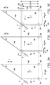
- Figures 3A, 3B and 3C show the potential impact of a lateral offset distance of the first longitudinal edge 91 on the length of the strip 9.
- figure 3A shows the strip 9 being correctly aligned and cut at or along the cutting line C.
- the first longitudinal edge 91 of the strip 9 is located on or is collinear with a lateral reference position R for said first longitudinal edge 91.
- the measuring line M is spaced apart from the cutting line C over a reference distance L1.
- the length of the first longitudinal edge 91 between the measuring line M and the cutting line C will be equal to said reference distance L1.
- Figures 3B and 3C show the potential length differences of said strip at the cutting line as a result of misalignment with respect to the correct alignment of figure 3A .
- the first longitudinal edge 91 is offset over a first lateral offset distance D1 in the lateral direction X with respect to the lateral reference position R.
- the length of the first longitudinal edge 91 between the measuring line M and the cutting line C has effectively increased to a larger length L2 than the reference distance L1.
- Figure 3C shows that when the first longitudinal edge 91 is offset in the opposite direction over a second lateral offset distance D2, the length of the first longitudinal edge 91 between the measuring line M and the cutting line C has effectively decreased to a smaller length L3 than the reference distance L1.
- the method according to the present invention intends to compensate for these length differences by determining a correction distance E1, E2, as shown in more detail in figures 4 and 5 , based on the lateral offset distance D1, D2 and by adding or subtracting said correction distance E1, E2 from the feeding distances F1, F2, F3, as shown in figures 6A-6D , over which the strip S is conveyed in the feeding direction F.
- the method according to the present invention comprises the following steps:
- the method further comprises the step of:
- the offset distance D1, D2, D3 can be determined by comparing the detected lateral position P1, P2 with the reference position R. Based on said the determined offset distance D1, D2, D3, one can calculate the correction distance E1, E2, E3 in the feeding direction F by using a trigonometric function, preferably a tangent, with a first parameter indicative of the cutting angle H and a second parameter indicative of the offset distance D1, D2, D3 as parameters.
- the cutting angle H may be entered into the apparatus 1 through manual input by an operator or the cutting angle H may be determined automatically, i.e. with suitable sensor means.
- a range of values indicative of the correction distance E1, E2, E3 associated with a range of lateral positions P1, P2 is stored in a database.
- the database may be part of the control unit 4 or located at a different location.
- the relationship between the correction distance E1, E2, E3 and the cutting angle H is not actively calculated. Instead, it may be determined by simply retrieving one value from the range of values that is associated with a lateral position P1, P2 from the range of lateral positions P1, P2 that corresponds or substantially corresponds to the detected lateral position P1, P2 of the first longitudinal edge 91.
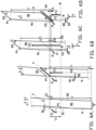
- FIGS 6A-6D show in more detail which parts of the feeding distance F1, F2, F3 are corrected at which moment and based on which detected lateral positions P1, P2.
- figure 6A shows the strip 9 with a section of the strip body 90 that is still continuous, i.e. uncut.
- a first lateral position P1 of the first longitudinal edge 91 is detected at the measuring line M upstream of the cutting line C with respect to the feeding direction F.
- the detection can be done by the first sensor 31 as shown in figure 2 .
- the second sensor 32 is not required and may be inactive.
- the control unit 4 receives detection signals representative of the first lateral position P1 from the sensor device 3 and determines a first correction distance E1 based on the aforementioned relationship between the first lateral position P1 and the cutting angle H.
- the strip 9 is subsequently fed over a first part F1 of the feeding distance F1, F2, F3 to move the part of the strip 9 that was located on the measuring line M during the detection of the first lateral position P1 towards the cutting line C.
- the first part F1 of the feeding distance F1, F2, F3 is corrected with the correction distance E1 such that the detected first lateral position P1 is located on the cutting line C after the feeding.
- the first part F1 of the feeding distance F1, F2, F3 is equal to the reference length L corrected with the first correction distance E1.
- the cutting line C intersects with the first longitudinal edge 91 in the first lateral position P1.
- the hatched part of the strip 9 in figure 6B is the part of the strip 9 that would have cut-off if no correction distance E1 was applied to the first part F1 of the feeding distance F1, F2, F3.
- Figure 6C shows the situation after the strip 9 has been cut to form the leading edge 93 and prior to cutting the strip 9 to form the trailing edge 94.
- an operator Before the trailing edge 94 is cut, an operator has input a parameter to set the length of the tire component.
- said parameter is an edge length L for the first longitudinal edge 91 or the second longitudinal edge 92.
- a predefined edge length L for the first longitudinal edge 91 is given.
- the strip 9 has been fed over a second part F2 of the feeding distance F1, F2, F3 that corresponds or substantially corresponds to the predefined edge length L minus the first part F1 of the feeding distance F1, F2, F3. Consequently, the strip 9 is now located with a section of the strip body 90 at the measuring line M where the strip 9 would be cut to create the trailing edge 94 based on the predefined edge length L.
- a second lateral position P2 of the first longitudinal edge 91 is detected at the measuring line M in the situation as shown in figure 6C .
- the detection can again be performed solely by the first sensor 31 as shown in figure 2 .
- the control unit 4 receives detection signals representative of the second lateral position P2 from the sensor device 3 and determines a second lateral offset distance D2 by comparing the detected second lateral position P2 with the reference position R.
- the control unit 4 can subsequently determine a second correction distance E2 based on the aforementioned relationship between the second lateral offset distance D2 and the cutting angle H.
- control unit 4 may compare the detected second lateral position P2 with the detected first lateral position P1 and determine a third or offset distance D3 based on the difference between said two lateral positions P1, P2. The control unit 4 may then determine a third or overall correction distance E3 based on the aforementioned relationship between the third or overall lateral offset distance D3 and the cutting angle H.
- the strip 9 can be fed further over a third part F3 of the feeding distance F1, F2, F3, as shown in figure 6D .
- the third part F3 of the feeding distance F1, F2, F3 is corrected with the second correction distance E2 so that the detected second lateral position P2 is located on the cutting line C.
- the third part F3 of the feeding distance F1, F2, F3 is equal to the reference distance L1, as shown in figure 3A , corrected with the second correction distance E2.
- the third part F3 of the feeding distance F1, F2, F3 is equal to the first part F1 of the feeding distance F1 corrected with the overall correction distance E3.
- the strip 9 may now be cut along the cutting line C to create the trailing edge 94. Note that the cutting line C intersects with the first longitudinal edge 91 exactly at the edge length L. Hence, a tire component can be obtained with an edge length L that is constant or substantially constant regardless of the offset of the first longitudinal edge 91 in the lateral direction X.
- the hatched part of the strip 9 in figure 6D is the part of the strip 9 that would have been included if no correction distance E2, E3 was applied to the third part F3 of the feeding distance F1, F2, F3.
- the trailing edge 94 of the tire component created during the abovementioned steps of the method inherently creates a leading edge 93 at the strip 9 directly upstream of said tire component.
- the creation of said leading edge 93 forms the start of a next cycle of the method.
- the detection of the second lateral position P2 in figure 6C may therefore be simultaneously the detection of the first lateral position P1 of a next cycle of the method, i.e. for cutting a next tire component out of the continuous strip 9.
- the detected second lateral position P2 may be used for determining the correction distance E2 required to obtain the desired edge length L of the current tire component, while the same correction distance E2 is also used as the correction distance E1 for cutting the leading edge 93 of the next tire component.
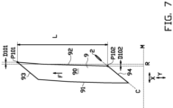
- Figure 7 illustrates schematically that the same or a similar detection and determination can also be performed along the second longitudinal edge 92 as if it were the first longitudinal edge 91.
- the second sensor 32 of figure 2 may be used to determine the lateral offset distances D101, D102 of the detected first lateral position P101 and the detected second lateral position P102 with respect to a reference position R for the second longitudinal edge 92.
- the embodiment of figure 7 has the additional advantage that the leading edge 93 can be cut from the sharp leading tip at the intersection between the second longitudinal edge 92 and the leading edge 93 towards the first longitudinal edge 91, which can provide greater accuracy when creating the leading tip.
- the invention relates to a method for correcting a feeding distance F1, F2, F3 of a strip 9 for cutting, wherein the method comprises the steps of:
Landscapes
- Engineering & Computer Science (AREA)
- Mechanical Engineering (AREA)
- Life Sciences & Earth Sciences (AREA)
- Forests & Forestry (AREA)
- Textile Engineering (AREA)
- Computer Vision & Pattern Recognition (AREA)
- Tyre Moulding (AREA)
- Registering, Tensioning, Guiding Webs, And Rollers Therefor (AREA)
- Control Of Cutting Processes (AREA)
- Controlling Sheets Or Webs (AREA)
Claims (16)
- Verfahren zur Korrektur einer Vorschubdistanz (F1, F2, F3) eines Bands (9) zum Schneiden, wobei das Band (9) einen sich in einer Längsrichtung (Y) erstreckenden Bandkörper (90), eine sich an einer ersten Seite des Bandkörpers (90) erstreckende erste Längskante (91) und eine sich an einer der ersten Seite gegenüberliegenden zweiten Seite des Bandkörpers (90) erstreckende zweite Längskante (92) aufweist, wobei das Verfahren die folgenden Schritte umfasst:- Vorschieben des Bands (9) über die Vorschubdistanz (F1, F2, F3) in einer Vorschubrichtung (F) zu einer Schnittlinie (C), die sich in einem schrägen Schnittwinkel (H) zu der Vorschubrichtung (F) erstreckt;- Erfassen einer seitlichen Position (P1, P2) der ersten Längskante (91) entlang einer Messlinie (M);dadurch gekennzeichnet, dass, wenn die erfasste seitliche Position (P1, P2) über eine Versatzdistanz (D1, D2, D3) in einer seitlichen Richtung (X) senkrecht zur Vorschubrichtung (F) in Bezug auf eine Referenzposition (R) für die erste Längskante (91) an der Messlinie (M) versetzt ist, das Verfahren ferner den Schritt umfasst:- Einstellen der Vorschubdistanz (F1, F2, F3) mit einer Korrekturdistanz (E1, E2, E3), die sich auf die Versatzdistanz (D1, D2) in einem Verhältnis bezieht, das durch den Schnittwinkel (H) definiert ist.
- Verfahren nach Anspruch 1, wobei die seitliche Position (P1, P2) der ersten Längskante (91) an der Messlinie (M) vor der Schnittlinie (C) in Bezug auf die Vorschubrichtung (F) erfasst wird,
wobei vorzugsweise die Referenzposition (R) an der Messlinie (M) in einer Referenz Korrekturdistanz (L1) von der Schnittlinie (C) in Vorschubrichtung (F) liegt, wobei die erfasste seitliche Position (P1, P2) um die Versatzdistanz (D1, D2, D3) versetzt entweder in einer größeren Distanz (L2) oder in einer kleineren Distanz (L3) von der Schnittlinie (C) in Vorschubrichtung (F) liegt als die Referenzdistanz (L1), wobei die Vorschubdistanz (F1, F2, F3) eingestellt wird, indem die Korrekturdistanz (E1) zu der Referenzdistanz (L1) im Falle der größeren Distanz (L2) addiert wird und indem die Korrekturdistanz (E2) von der Referenzdistanz (L1) im Falle der kleineren Distanz (L3) subtrahiert wird. - Verfahren nach einem der vorhergehenden Ansprüche, wobei das Verfahren die folgenden Schritte umfasst:- Vergleichen der erfassten seitlichen Position (P1, P2) mit der Referenzposition (R), um die Versatzdistanz (D1, D2, D3) zu bestimmen; und- Berechnen der Korrekturdistanz (E1, E2, E3) in der Vorschubrichtung (F) unter Verwendung einer trigonometrischen Funktion mit einem ersten Parameter, der den Schnittwinkel (H) angibt, und einem zweiten Parameter, der die Versatzdistanz (D1, D2, D3) angibt, als Parameter; und- Einstellen der Vorschubdistanz (F1, F2, F3) auf der Grundlage der berechneten Korrekturdistanz (E1, E2, E3).
- Verfahren nach Anspruch 3, wobei die trigonometrische Funktion ein Tangens ist.
- Verfahren nach Anspruch 4, wobei die trigonometrische Funktion lautet

wobei die trigonometrische Funktion lautet
- Verfahren nach Anspruch 1 oder 2, wobei ein Bereich von Werten, die die Korrekturdistanz (E1, E2, E3) anzeigen, der einem Bereich von seitlichen Positionen (P1, p2) zugeordnet ist, in einer Datenbank gespeichert wird, wobei das Verfahren die folgenden Schritte umfasst:- Abrufen eines Wertes aus dem Wertebereich, der einer seitlichen Position (P1, P2) aus dem Bereich der seitlichen Positionen (P1, P2) zugeordnet ist, die der erfassten seitlichen Position (P1, P2) der ersten Längskante (91) entspricht oder im Wesentlichen entspricht, und Verwenden dieses Wertes als die Korrekturdistanz (E1, E2, E3), um die Vorschubdistanz (F1, F2, F3) einzustellen.
- Verfahren nach einem der vorhergehenden Ansprüche, wobei die Referenzposition (R) eine feste Position ist.
- Verfahren nach einem der Ansprüche 1 bis 6, wobei das Verfahren die folgenden Schritte umfasst:- Schneiden des Bands (9) an der Schnittlinie (C) zur Bildung einer Vorderkante (93) in Bezug auf die Vorschubrichtung (F) ;- Vorschieben des Bands (9) in der Vorschubrichtung (F) über die Vorschubdistanz (F1, F2, F3); und- Schneiden des Bands (9) an der Schnittlinie (C), um eine Hinterkante (94) in Bezug auf die Vorschubrichtung (F) zu bilden;wobei die erste Längskante (91) eine Kantenlänge (L) in der Vorschubrichtung (F) zwischen der Vorderkante (93) und der Hinterkante (94) aufweist; undwobei, wenn die seitliche Position (P1, P2) der ersten Längskante (91) in der seitlichen Richtung (X) an der Hinterkante (94) in Bezug auf die Vorderkante (93) versetzt ist, die Vorschubdistanz (F1, F2, F3) mit der Korrekturdistanz (E1, E2, E3) so eingestellt wird, dass die Kantenlänge (L) unabhängig von dem Versatz konstant oder im Wesentlichen konstant ist.
- Verfahren nach Anspruch 8, wobei die seitliche Position (P1, P2) der ersten Längskante (91) mindestens zweimal entlang der Kantenlänge (L) erfasst wird, wobei eine erfasste erste seitliche Position (P1) der mindestens zwei erfassten seitlichen Positionen (P1, P2) als Referenzposition (R) zur Bestimmung der Versatzdistanz (D3) für eine erfasste zweite seitliche Position (P2) der mindestens zwei erfassten seitlichen Positionen (P1, P2) verwendet wird, wobei vorzugsweise die erfasste erste seitliche Position (P1) von der erfassten zweiten seitlichen Position (P2) in Vorschubrichtung (F) über die Kantenlänge (L) beabstandet ist.
- Verfahren nach Anspruch 9, wobei die erfasste erste seitliche Position (P1) die seitliche Position der ersten Längskante (91) an der Vorderkante (93) ist und die erfasste zweite seitliche Position (P2) die seitliche Position der ersten Längskante (91) an der Hinterkante (94) ist.
- Verfahren nach einem der Ansprüche 8 bis 10, wobei das Verfahren vor dem Schneiden des Bands (9) zur Bildung der Vorderkante (93) die folgenden Schritte umfasst:- Erfassen einer ersten seitlichen Position (P1) der ersten Längskante (91) an der Messlinie (M) stromaufwärts der Schnittlinie (C) in Bezug auf die Vorschubrichtung (F); und- Vorschieben des Bands (9) über einen ersten Teil (F1) der Vorschubdistanz (F1, F2, F3), der mit der Korrekturdistanz (E1) korrigiert wird, so dass sich die erfasste erste seitliche Position (P1) nach dem Vorschieben des Bands (9) über den ersten Teil (F1) der Vorschubdistanz (F1, F2, F3) auf der Schnittlinie (C) befindet,
wobei das Verfahren vorzugsweise nach dem Schneiden des Bands (9) zur Bildung der Vorderkante (93) und vor dem Schneiden des Bands (9) zur Bildung der Hinterkante (94) die folgenden Schritte umfasst:- Vorschieben des Bands (9) über einen zweiten Teil (F2) der Vorschubdistanz (F1, F2, F3), der der Kantenlänge (L) minus dem ersten Teil (F1) der Vorschubdistanz (F1, F2, F3) entspricht oder im Wesentlichen entspricht;- Erfassen einer zweiten seitlichen Position (P2) der ersten Längskante (91) an der Messlinie (M); und- Vorschieben des Bands (9) über einen dritten Teil (F3) der Vorschubdistanz (F1, F2, F3), der mit der Korrekturdistanz (E2, E3) korrigiert wird, so dass die erfasste zweite seitliche Position (P2) auf der Schnittlinie (C) nach dem Vorschieben des Bands (9) über den dritten Teil (F3) der Vorschubdistanz (F1, F2, F3) liegt. - Verfahren nach einem der vorhergehenden Ansprüche, wobei die seitliche Position (P1, P2) der ersten Längskante (91) an der Messlinie (M) in Bezug auf die Vorschubrichtung (F) vor der Schnittlinie (C) erfasst wird, wobei die Schnittlinie (C) an der ersten Längskante (91) oder der zweiten Längskante (92) zur Messlinie (M) hin konvergiert,
wobei vorzugsweise die Schnittlinie (C) so einstellbar ist, dass sie sich in einem alternativen schrägen Schnittwinkel zur Vorschubrichtung (F) erstreckt, wobei die Schnittlinie (C) an der anderen der ersten Längskante (91) und der zweiten Längskante (92) zur Messlinie (M) konvergiert, wobei die Verfahrensschritte in Bezug auf die zweite Längskante (92) anstelle der ersten Längskante (91) durchgeführt werden, wenn sich die Schnittlinie (C) in dem alternativen schrägen Schnittwinkel erstreckt. - Verfahren nach einem der vorhergehenden Ansprüche, wobei die Messlinie (M) in der seitlichen Richtung (X) senkrecht zur Vorschubrichtung (F) verläuft.
- Vorrichtung (1) zur Korrektur einer Vorschubdistanz (F1, F2, F3) eines zu schneidenden Bands (9), wobei das Band (9) einen sich in einer Längsrichtung (Y) erstreckenden Bandkörper (90), eine sich an einer ersten Seite des Bandkörpers (90) erstreckende erste Längskante (91) und eine sich an einer der ersten Seite gegenüberliegenden zweiten Seite des Bandkörpers (90) erstreckende zweite Längskante (92) aufweist, wobei die Vorrichtung (1) umfasst:- einen Schneider (2) zum Schneiden des Bands (9) entlang einer Schnittlinie (C);- einen Förderer (11) zum Vorschieben des Bands (9) über die Vorschubdistanz (F1, F2, F3) in einer Vorschubrichtung (F) in Richtung der Schnittlinie (C), wobei sich die Schnittlinie (C) in einem schrägen Schnittwinkel (H) zu der Vorschubrichtung (F) erstreckt- einen Antrieb (10) zum Steuern des Förderers (11);- eine Sensoreinrichtung (3) zur Erfassung einer seitlichen Position (P1, P2) der ersten Längskante (91) entlang einer Messlinie (M); und- eine Steuereinheit (4), die mit der Sensoreinrichtung (3) und dem Antrieb (10) in Wirkverbindung steht,
dadurch gekennzeichnet, dass die Steuereinheit (4) ausgebildet ist zum:
Anpassen der Vorschubdistanz (F1, F2, F3), wenn die erfasste seitliche Position (P1, P2) um eine Versatzdistanz (D1, D2) in einer seitlichen Richtung (X) senkrecht zur Vorschubrichtung (F) gegenüber einer Referenzposition (R) für die erste Längskante (91) an der Messlinie (M) versetzt ist, wobei die Vorschubdistanz (F1, F2, F3) mit einer Korrekturdistanz (E1, E2, E3) eingestellt wird, die mit der Versatzdistanz (D1, D2) in einem Verhältnis steht, das durch den Schnittwinkel (H) definiert ist. - Vorrichtung (1) nach Anspruch 19, wobei die Messlinie (M) in Bezug auf die Vorschubrichtung (F) vor der Schnittlinie (C) angeordnet ist und/oder wobei die Messlinie (M) in der seitlichen Richtung (X) senkrecht zur Vorschubrichtung (F) verläuft.
- Vorrichtung (1) nach Anspruch 14 oder 15, wobei die Sensoreinrichtung (3) einen ersten Sensor (31) zur Erfassung der seitlichen Position (P1, P2) der ersten Längskante (91) entlang der Messlinie (M) aufweist,
wobei die Sensoreinrichtung (3) vorzugsweise einen zweiten Sensor (32) zur Erfassung der seitlichen Position (P1, P2) der zweiten Längskante (92) aufweist, wobei die Schnittlinie (C) in einem alternativen Schrägschnittwinkel zur Vorschubrichtung (F) verstellbar ist, wobei die Steuereinheit (4) zur Einstellung der Vorschubdistanz (F1, F2, F3) in Abhängigkeit von der erfassten seitlichen Position (P1, P2) der zweiten Längskante (91) anstelle der ersten Längskante (91) eingerichtet ist, wenn die Schnittlinie (C) in dem alternativen Schrägschnittwinkel verläuft.
Priority Applications (1)
| Application Number | Priority Date | Filing Date | Title |
|---|---|---|---|
| RS20240185A RS65162B1 (sr) | 2019-10-18 | 2020-09-24 | Postupak i aparatura za korigovanje rastojanja dopremanja trake za sečenje |
Applications Claiming Priority (2)
| Application Number | Priority Date | Filing Date | Title |
|---|---|---|---|
| NL2024050A NL2024050B1 (en) | 2019-10-18 | 2019-10-18 | Method and apparatus for correcting a feeding distance of a strip for cutting |
| PCT/EP2020/076747 WO2021073850A1 (en) | 2019-10-18 | 2020-09-24 | Method and apparatus for correcting a feeding distance of a strip for cutting |
Publications (3)
| Publication Number | Publication Date |
|---|---|
| EP4045447A1 EP4045447A1 (de) | 2022-08-24 |
| EP4045447C0 EP4045447C0 (de) | 2023-11-29 |
| EP4045447B1 true EP4045447B1 (de) | 2023-11-29 |
Family
ID=68807355
Family Applications (1)
| Application Number | Title | Priority Date | Filing Date |
|---|---|---|---|
| EP20775021.7A Active EP4045447B1 (de) | 2019-10-18 | 2020-09-24 | Verfahren und vorrichtung zur korrektur der vorschubstrecke eines bandes zum schneiden |
Country Status (13)
| Country | Link |
|---|---|
| US (1) | US11634296B2 (de) |
| EP (1) | EP4045447B1 (de) |
| JP (1) | JP7138231B2 (de) |
| KR (1) | KR102528705B1 (de) |
| CN (1) | CN112677218B (de) |
| BR (1) | BR112022007189A2 (de) |
| HU (1) | HUE065508T2 (de) |
| MX (1) | MX2022004527A (de) |
| NL (1) | NL2024050B1 (de) |
| PL (1) | PL4045447T3 (de) |
| RS (1) | RS65162B1 (de) |
| TW (1) | TW202116539A (de) |
| WO (1) | WO2021073850A1 (de) |
Families Citing this family (3)
| Publication number | Priority date | Publication date | Assignee | Title |
|---|---|---|---|---|
| CA3142129A1 (en) * | 2019-06-17 | 2020-12-24 | 1045929 Ontario Limited | Sod harvesting systems and related methods |
| CN118875520B (zh) * | 2024-08-19 | 2025-09-26 | 大族激光科技产业集团股份有限公司 | 卷料多切割头寻边方法、装置、切割设备和存储介质 |
| CN119036547A (zh) * | 2024-11-01 | 2024-11-29 | 成都市棠德家具有限公司 | 一种用于卷材切割的定位方法及切割装置 |
Family Cites Families (22)
| Publication number | Priority date | Publication date | Assignee | Title |
|---|---|---|---|---|
| US2261837A (en) * | 1940-06-29 | 1941-11-04 | Firestone Tire & Rubber Co | Bias cutter |
| US4824515A (en) * | 1983-05-09 | 1989-04-25 | The Firestone Tire & Rubber Company | Ply applicator |
| JP3020991B2 (ja) * | 1990-04-05 | 2000-03-15 | 株式会社ブリヂストン | 帯状部材巻付方法および装置 |
| FR2694519A1 (fr) * | 1992-08-07 | 1994-02-11 | Sedepro | Procédé de fabrication d'un pneumatique et machine de fabrication d'un renfort de sommet pour pneumatique. |
| DE19641509C2 (de) | 1996-10-09 | 1999-06-24 | Continental Ag | Verfahren zum Transport eines Gürtelaufbaustreifens zum Aufbau eines Gürtels für einen Fahrzeugluftreifen |
| AU2001258926A1 (en) | 2000-05-17 | 2001-11-26 | Vmi-Epe-Holland B.V. | Supply device for supplying rubber material to a cutting device |
| JP2002370194A (ja) * | 2001-06-14 | 2002-12-24 | Nippon Reliance Kk | 定尺切断装置における対角寸法測定方法および装置 |
| DE602004005090T2 (de) * | 2003-02-13 | 2007-12-13 | Société de Technologie Michelin | Formgebung und Anlegen einer Reifengürtellage auf eine Haltevorrichtung |
| US8016968B2 (en) * | 2005-07-29 | 2011-09-13 | Xerox Corporation | Process for producing an imaging member belt having an angular seam |
| JP5345244B2 (ja) | 2010-03-16 | 2013-11-20 | 株式会社ニレコ | ウェブ中心位置制御装置、方法及びプログラム並びにウェブトリミング装置 |
| FR2960180B1 (fr) * | 2010-05-21 | 2012-06-15 | Soc Tech Michelin | Dispositif d'ajustement d'un front de nappe |
| KR20140040126A (ko) * | 2011-04-12 | 2014-04-02 | 하부르크-프로이덴베르거 마쉬넨바우 게엠베하 | 벨트 스트립을 정렬하기 위한 장치 및 방법 |
| TWI616293B (zh) * | 2012-04-04 | 2018-03-01 | 住友化學股份有限公司 | 薄膜切斷方法及薄膜切斷系統 |
| JP6100083B2 (ja) | 2013-05-10 | 2017-03-22 | 株式会社ブリヂストン | 一定長さにカットされた部材の巻付体への巻付方法及び巻付体への部材の巻付装置 |
| NL2011764C2 (en) * | 2013-11-08 | 2015-05-11 | Vmi Holland Bv | Method for centering a tire component. |
| EP3132926B1 (de) | 2014-04-15 | 2019-03-06 | Bridgestone Corporation | Vorrichtung für die zuführung von reifenmaterialelementen und verfahren für die zuführung von reifenmaterialelementen |
| DE102016116798A1 (de) | 2016-09-08 | 2018-03-08 | Dieffenbacher GmbH Maschinen- und Anlagenbau | Tapelegevorrichtung und Tapelegeverfahren mit verschwenkbarer Schneideinrichtung |
| NL2018057B1 (en) | 2016-12-23 | 2018-07-02 | Vmi Holland Bv | Cutting device and method for cutting-off a length of a continuous strip to form a tire component |
| NL2018959B1 (en) * | 2017-05-22 | 2018-12-04 | Vmi Holland Bv | Method and assembly for applying a tire component to a drum |
| BR112020012051B1 (pt) * | 2017-12-19 | 2023-04-04 | Compagnie Generale Des Etablissements Michelin | Método para colocar uma lona de reforço em um tambor de grande dimensão |
| FR3088566B3 (fr) * | 2018-11-16 | 2020-11-13 | Michelin & Cie | Systeme de coupe de bandelettes par couteaux helicoidaux et procede de coupe correspondant |
| JP7762647B2 (ja) * | 2019-09-04 | 2025-10-30 | ザ スティーラスティック カンパニー リミテッド ライアビリティ カンパニー | 様々なタイヤベルトサイズのための移送ツーリング |
-
2019
- 2019-10-18 NL NL2024050A patent/NL2024050B1/en not_active IP Right Cessation
-
2020
- 2020-09-24 RS RS20240185A patent/RS65162B1/sr unknown
- 2020-09-24 KR KR1020227016533A patent/KR102528705B1/ko active Active
- 2020-09-24 JP JP2021503035A patent/JP7138231B2/ja active Active
- 2020-09-24 MX MX2022004527A patent/MX2022004527A/es unknown
- 2020-09-24 EP EP20775021.7A patent/EP4045447B1/de active Active
- 2020-09-24 US US17/769,989 patent/US11634296B2/en active Active
- 2020-09-24 PL PL20775021.7T patent/PL4045447T3/pl unknown
- 2020-09-24 BR BR112022007189A patent/BR112022007189A2/pt unknown
- 2020-09-24 HU HUE20775021A patent/HUE065508T2/hu unknown
- 2020-09-24 WO PCT/EP2020/076747 patent/WO2021073850A1/en not_active Ceased
- 2020-10-06 TW TW109134591A patent/TW202116539A/zh unknown
- 2020-10-16 CN CN202011110782.6A patent/CN112677218B/zh active Active
Also Published As
| Publication number | Publication date |
|---|---|
| CN112677218B (zh) | 2023-08-15 |
| KR20220083790A (ko) | 2022-06-20 |
| PL4045447T3 (pl) | 2024-04-29 |
| BR112022007189A2 (pt) | 2022-06-28 |
| EP4045447C0 (de) | 2023-11-29 |
| NL2024050B1 (en) | 2021-06-22 |
| TW202116539A (zh) | 2021-05-01 |
| US11634296B2 (en) | 2023-04-25 |
| JP7138231B2 (ja) | 2022-09-15 |
| US20220363506A1 (en) | 2022-11-17 |
| MX2022004527A (es) | 2022-07-05 |
| KR102528705B1 (ko) | 2023-05-03 |
| JP2022513551A (ja) | 2022-02-09 |
| WO2021073850A1 (en) | 2021-04-22 |
| EP4045447A1 (de) | 2022-08-24 |
| RS65162B1 (sr) | 2024-02-29 |
| HUE065508T2 (hu) | 2024-05-28 |
| CN112677218A (zh) | 2021-04-20 |
Similar Documents
| Publication | Publication Date | Title |
|---|---|---|
| EP4045447B1 (de) | Verfahren und vorrichtung zur korrektur der vorschubstrecke eines bandes zum schneiden | |
| CN103596750B (zh) | 用于束带帘布层的定向的方法和装置 | |
| EP1727667B1 (de) | Schneideinrichtung | |
| CN104520055B (zh) | 用于切割金属薄板胚料的方法 | |
| CN102026766B (zh) | 线电极放电加工装置、以及线电极放电加工方法 | |
| JP6693769B2 (ja) | ロールフィーダ、およびコイル材搬送方法 | |
| CN107433287A (zh) | 一种热轧飞剪头尾剪切起始位置的动态控制方法 | |
| US5752593A (en) | Belt feeder centering method and apparatus | |
| JP4089057B2 (ja) | フィルムエッジ厚み測定装置及びフィルムエッジ厚み測定方法 | |
| JP2017226128A (ja) | 製袋機およびその制御方法 | |
| US20130199697A1 (en) | Device for Adjusting a Layer Front | |
| CN1946544B (zh) | 切割工具 | |
| KR20140002893A (ko) | 나이프 정렬장치 및 그 나이프 정렬방법 | |
| KR101091171B1 (ko) | 열간 압연에서의 크롭 쉬어 구동 제어방법 | |
| JP3484882B2 (ja) | 板材の切断装置 | |
| KR101403474B1 (ko) | 다중 센서를 이용한 사행 보정제어장치 | |
| JPH04279324A (ja) | キャップトレッドのセンターリング方法 | |
| KR102370392B1 (ko) | 냉연공정 소재의 두께 제어 장치 및 제어 방법 | |
| JP2502623Y2 (ja) | ロ―ル紙定寸切断装置の切断長補正装置 | |
| CN117021641A (zh) | 成型机带束层控制贴合精度的系统及方法 | |
| KR101701645B1 (ko) | 강판 선단부 벤딩 교정 장치 및 방법 | |
| JP3521987B2 (ja) | 帯状シート材料継目部の段付修正方法 | |
| NL1025767C2 (nl) | Inrichting voor het aanbrengen van een gordellaag, en snijinrichting daarvoor. | |
| JPH09136211A (ja) | サイドトリマ部の鋼帯通板位置制御方法 | |
| JPH07326240A (ja) | フラットケーブルの製造方法 |
Legal Events
| Date | Code | Title | Description |
|---|---|---|---|
| STAA | Information on the status of an ep patent application or granted ep patent |
Free format text: STATUS: UNKNOWN |
|
| STAA | Information on the status of an ep patent application or granted ep patent |
Free format text: STATUS: THE INTERNATIONAL PUBLICATION HAS BEEN MADE |
|
| PUAI | Public reference made under article 153(3) epc to a published international application that has entered the european phase |
Free format text: ORIGINAL CODE: 0009012 |
|
| STAA | Information on the status of an ep patent application or granted ep patent |
Free format text: STATUS: REQUEST FOR EXAMINATION WAS MADE |
|
| 17P | Request for examination filed |
Effective date: 20220308 |
|
| AK | Designated contracting states |
Kind code of ref document: A1 Designated state(s): AL AT BE BG CH CY CZ DE DK EE ES FI FR GB GR HR HU IE IS IT LI LT LU LV MC MK MT NL NO PL PT RO RS SE SI SK SM TR |
|
| DAV | Request for validation of the european patent (deleted) | ||
| DAX | Request for extension of the european patent (deleted) | ||
| STAA | Information on the status of an ep patent application or granted ep patent |
Free format text: STATUS: EXAMINATION IS IN PROGRESS |
|
| 17Q | First examination report despatched |
Effective date: 20230622 |
|
| REG | Reference to a national code |
Ref country code: DE Ref legal event code: R079 Free format text: PREVIOUS MAIN CLASS: B65H0035000000 Ipc: B26D0003000000 Ref document number: 602020021962 Country of ref document: DE |
|
| GRAP | Despatch of communication of intention to grant a patent |
Free format text: ORIGINAL CODE: EPIDOSNIGR1 |
|
| STAA | Information on the status of an ep patent application or granted ep patent |
Free format text: STATUS: GRANT OF PATENT IS INTENDED |
|
| RIC1 | Information provided on ipc code assigned before grant |
Ipc: B65H 23/032 20060101ALI20230822BHEP Ipc: B29D 30/46 20060101ALI20230822BHEP Ipc: B29D 30/42 20060101ALI20230822BHEP Ipc: B65H 23/02 20060101ALI20230822BHEP Ipc: B29D 30/38 20060101ALI20230822BHEP Ipc: B65H 35/00 20060101ALI20230822BHEP Ipc: B26D 7/01 20060101ALI20230822BHEP Ipc: B26D 5/00 20060101ALI20230822BHEP Ipc: B26D 3/00 20060101AFI20230822BHEP |
|
| INTG | Intention to grant announced |
Effective date: 20230908 |
|
| GRAS | Grant fee paid |
Free format text: ORIGINAL CODE: EPIDOSNIGR3 |
|
| GRAA | (expected) grant |
Free format text: ORIGINAL CODE: 0009210 |
|
| STAA | Information on the status of an ep patent application or granted ep patent |
Free format text: STATUS: THE PATENT HAS BEEN GRANTED |
|
| AK | Designated contracting states |
Kind code of ref document: B1 Designated state(s): AL AT BE BG CH CY CZ DE DK EE ES FI FR GB GR HR HU IE IS IT LI LT LU LV MC MK MT NL NO PL PT RO RS SE SI SK SM TR |
|
| REG | Reference to a national code |
Ref country code: GB Ref legal event code: FG4D |
|
| REG | Reference to a national code |
Ref country code: CH Ref legal event code: EP |
|
| REG | Reference to a national code |
Ref country code: DE Ref legal event code: R096 Ref document number: 602020021962 Country of ref document: DE |
|
| REG | Reference to a national code |
Ref country code: IE Ref legal event code: FG4D |
|
| U01 | Request for unitary effect filed |
Effective date: 20231206 |
|
| U07 | Unitary effect registered |
Designated state(s): AT BE BG DE DK EE FI FR IT LT LU LV MT NL PT SE SI Effective date: 20231212 |
|
| PG25 | Lapsed in a contracting state [announced via postgrant information from national office to epo] |
Ref country code: GR Free format text: LAPSE BECAUSE OF FAILURE TO SUBMIT A TRANSLATION OF THE DESCRIPTION OR TO PAY THE FEE WITHIN THE PRESCRIBED TIME-LIMIT Effective date: 20240301 |
|
| PG25 | Lapsed in a contracting state [announced via postgrant information from national office to epo] |
Ref country code: IS Free format text: LAPSE BECAUSE OF FAILURE TO SUBMIT A TRANSLATION OF THE DESCRIPTION OR TO PAY THE FEE WITHIN THE PRESCRIBED TIME-LIMIT Effective date: 20240329 |
|
| REG | Reference to a national code |
Ref country code: SK Ref legal event code: T3 Ref document number: E 43627 Country of ref document: SK |
|
| PG25 | Lapsed in a contracting state [announced via postgrant information from national office to epo] |
Ref country code: ES Free format text: LAPSE BECAUSE OF FAILURE TO SUBMIT A TRANSLATION OF THE DESCRIPTION OR TO PAY THE FEE WITHIN THE PRESCRIBED TIME-LIMIT Effective date: 20231129 |
|
| PG25 | Lapsed in a contracting state [announced via postgrant information from national office to epo] |
Ref country code: IS Free format text: LAPSE BECAUSE OF FAILURE TO SUBMIT A TRANSLATION OF THE DESCRIPTION OR TO PAY THE FEE WITHIN THE PRESCRIBED TIME-LIMIT Effective date: 20240329 Ref country code: GR Free format text: LAPSE BECAUSE OF FAILURE TO SUBMIT A TRANSLATION OF THE DESCRIPTION OR TO PAY THE FEE WITHIN THE PRESCRIBED TIME-LIMIT Effective date: 20240301 Ref country code: ES Free format text: LAPSE BECAUSE OF FAILURE TO SUBMIT A TRANSLATION OF THE DESCRIPTION OR TO PAY THE FEE WITHIN THE PRESCRIBED TIME-LIMIT Effective date: 20231129 |
|
| REG | Reference to a national code |
Ref country code: HU Ref legal event code: AG4A Ref document number: E065508 Country of ref document: HU |
|
| PG25 | Lapsed in a contracting state [announced via postgrant information from national office to epo] |
Ref country code: NO Free format text: LAPSE BECAUSE OF FAILURE TO SUBMIT A TRANSLATION OF THE DESCRIPTION OR TO PAY THE FEE WITHIN THE PRESCRIBED TIME-LIMIT Effective date: 20240229 Ref country code: HR Free format text: LAPSE BECAUSE OF FAILURE TO SUBMIT A TRANSLATION OF THE DESCRIPTION OR TO PAY THE FEE WITHIN THE PRESCRIBED TIME-LIMIT Effective date: 20231129 |
|
| PG25 | Lapsed in a contracting state [announced via postgrant information from national office to epo] |
Ref country code: CZ Free format text: LAPSE BECAUSE OF FAILURE TO SUBMIT A TRANSLATION OF THE DESCRIPTION OR TO PAY THE FEE WITHIN THE PRESCRIBED TIME-LIMIT Effective date: 20231129 |
|
| PG25 | Lapsed in a contracting state [announced via postgrant information from national office to epo] |
Ref country code: SM Free format text: LAPSE BECAUSE OF FAILURE TO SUBMIT A TRANSLATION OF THE DESCRIPTION OR TO PAY THE FEE WITHIN THE PRESCRIBED TIME-LIMIT Effective date: 20231129 Ref country code: RO Free format text: LAPSE BECAUSE OF FAILURE TO SUBMIT A TRANSLATION OF THE DESCRIPTION OR TO PAY THE FEE WITHIN THE PRESCRIBED TIME-LIMIT Effective date: 20231129 Ref country code: CZ Free format text: LAPSE BECAUSE OF FAILURE TO SUBMIT A TRANSLATION OF THE DESCRIPTION OR TO PAY THE FEE WITHIN THE PRESCRIBED TIME-LIMIT Effective date: 20231129 |
|
| U20 | Renewal fee for the european patent with unitary effect paid |
Year of fee payment: 5 Effective date: 20240709 |
|
| REG | Reference to a national code |
Ref country code: DE Ref legal event code: R097 Ref document number: 602020021962 Country of ref document: DE |
|
| PLBE | No opposition filed within time limit |
Free format text: ORIGINAL CODE: 0009261 |
|
| STAA | Information on the status of an ep patent application or granted ep patent |
Free format text: STATUS: NO OPPOSITION FILED WITHIN TIME LIMIT |
|
| 26N | No opposition filed |
Effective date: 20240830 |
|
| PG25 | Lapsed in a contracting state [announced via postgrant information from national office to epo] |
Ref country code: MC Free format text: LAPSE BECAUSE OF FAILURE TO SUBMIT A TRANSLATION OF THE DESCRIPTION OR TO PAY THE FEE WITHIN THE PRESCRIBED TIME-LIMIT Effective date: 20231129 |
|
| REG | Reference to a national code |
Ref country code: CH Ref legal event code: PL |
|
| GBPC | Gb: european patent ceased through non-payment of renewal fee |
Effective date: 20240924 |
|
| PG25 | Lapsed in a contracting state [announced via postgrant information from national office to epo] |
Ref country code: GB Free format text: LAPSE BECAUSE OF NON-PAYMENT OF DUE FEES Effective date: 20240924 |
|
| PG25 | Lapsed in a contracting state [announced via postgrant information from national office to epo] |
Ref country code: CH Free format text: LAPSE BECAUSE OF NON-PAYMENT OF DUE FEES Effective date: 20240930 |
|
| PG25 | Lapsed in a contracting state [announced via postgrant information from national office to epo] |
Ref country code: IE Free format text: LAPSE BECAUSE OF NON-PAYMENT OF DUE FEES Effective date: 20240924 |
|
| PGFP | Annual fee paid to national office [announced via postgrant information from national office to epo] |
Ref country code: PL Payment date: 20250911 Year of fee payment: 6 |
|
| PGFP | Annual fee paid to national office [announced via postgrant information from national office to epo] |
Ref country code: HU Payment date: 20250922 Year of fee payment: 6 |
|
| PGFP | Annual fee paid to national office [announced via postgrant information from national office to epo] |
Ref country code: RS Payment date: 20250912 Year of fee payment: 6 |
|
| PGFP | Annual fee paid to national office [announced via postgrant information from national office to epo] |
Ref country code: SK Payment date: 20250916 Year of fee payment: 6 |
|
| U20 | Renewal fee for the european patent with unitary effect paid |
Year of fee payment: 6 Effective date: 20250924 |