EP4045273B1 - Extrusionsvorrichtung und extrusionsverfahren - Google Patents
Extrusionsvorrichtung und extrusionsverfahren Download PDFInfo
- Publication number
- EP4045273B1 EP4045273B1 EP20793615.4A EP20793615A EP4045273B1 EP 4045273 B1 EP4045273 B1 EP 4045273B1 EP 20793615 A EP20793615 A EP 20793615A EP 4045273 B1 EP4045273 B1 EP 4045273B1
- Authority
- EP
- European Patent Office
- Prior art keywords
- profile
- extrusion
- parameter
- calibration
- control
- Prior art date
- Legal status (The legal status is an assumption and is not a legal conclusion. Google has not performed a legal analysis and makes no representation as to the accuracy of the status listed.)
- Active
Links
Images


Classifications
-
- B—PERFORMING OPERATIONS; TRANSPORTING
- B29—WORKING OF PLASTICS; WORKING OF SUBSTANCES IN A PLASTIC STATE IN GENERAL
- B29C—SHAPING OR JOINING OF PLASTICS; SHAPING OF MATERIAL IN A PLASTIC STATE, NOT OTHERWISE PROVIDED FOR; AFTER-TREATMENT OF THE SHAPED PRODUCTS, e.g. REPAIRING
- B29C48/00—Extrusion moulding, i.e. expressing the moulding material through a die or nozzle which imparts the desired form; Apparatus therefor
- B29C48/25—Component parts, details or accessories; Auxiliary operations
- B29C48/92—Measuring, controlling or regulating
-
- B—PERFORMING OPERATIONS; TRANSPORTING
- B29—WORKING OF PLASTICS; WORKING OF SUBSTANCES IN A PLASTIC STATE IN GENERAL
- B29C—SHAPING OR JOINING OF PLASTICS; SHAPING OF MATERIAL IN A PLASTIC STATE, NOT OTHERWISE PROVIDED FOR; AFTER-TREATMENT OF THE SHAPED PRODUCTS, e.g. REPAIRING
- B29C48/00—Extrusion moulding, i.e. expressing the moulding material through a die or nozzle which imparts the desired form; Apparatus therefor
- B29C48/25—Component parts, details or accessories; Auxiliary operations
- B29C48/88—Thermal treatment of the stream of extruded material, e.g. cooling
- B29C48/90—Thermal treatment of the stream of extruded material, e.g. cooling with calibration or sizing, i.e. combined with fixing or setting of the final dimensions of the extruded article
- B29C48/901—Thermal treatment of the stream of extruded material, e.g. cooling with calibration or sizing, i.e. combined with fixing or setting of the final dimensions of the extruded article of hollow bodies
- B29C48/903—Thermal treatment of the stream of extruded material, e.g. cooling with calibration or sizing, i.e. combined with fixing or setting of the final dimensions of the extruded article of hollow bodies externally
-
- B—PERFORMING OPERATIONS; TRANSPORTING
- B29—WORKING OF PLASTICS; WORKING OF SUBSTANCES IN A PLASTIC STATE IN GENERAL
- B29C—SHAPING OR JOINING OF PLASTICS; SHAPING OF MATERIAL IN A PLASTIC STATE, NOT OTHERWISE PROVIDED FOR; AFTER-TREATMENT OF THE SHAPED PRODUCTS, e.g. REPAIRING
- B29C48/00—Extrusion moulding, i.e. expressing the moulding material through a die or nozzle which imparts the desired form; Apparatus therefor
- B29C48/001—Combinations of extrusion moulding with other shaping operations
- B29C48/0022—Combinations of extrusion moulding with other shaping operations combined with cutting
-
- B—PERFORMING OPERATIONS; TRANSPORTING
- B29—WORKING OF PLASTICS; WORKING OF SUBSTANCES IN A PLASTIC STATE IN GENERAL
- B29C—SHAPING OR JOINING OF PLASTICS; SHAPING OF MATERIAL IN A PLASTIC STATE, NOT OTHERWISE PROVIDED FOR; AFTER-TREATMENT OF THE SHAPED PRODUCTS, e.g. REPAIRING
- B29C48/00—Extrusion moulding, i.e. expressing the moulding material through a die or nozzle which imparts the desired form; Apparatus therefor
- B29C48/03—Extrusion moulding, i.e. expressing the moulding material through a die or nozzle which imparts the desired form; Apparatus therefor characterised by the shape of the extruded material at extrusion
- B29C48/12—Articles with an irregular circumference when viewed in cross-section, e.g. window profiles
-
- B—PERFORMING OPERATIONS; TRANSPORTING
- B29—WORKING OF PLASTICS; WORKING OF SUBSTANCES IN A PLASTIC STATE IN GENERAL
- B29C—SHAPING OR JOINING OF PLASTICS; SHAPING OF MATERIAL IN A PLASTIC STATE, NOT OTHERWISE PROVIDED FOR; AFTER-TREATMENT OF THE SHAPED PRODUCTS, e.g. REPAIRING
- B29C48/00—Extrusion moulding, i.e. expressing the moulding material through a die or nozzle which imparts the desired form; Apparatus therefor
- B29C48/25—Component parts, details or accessories; Auxiliary operations
- B29C48/269—Extrusion in non-steady condition, e.g. start-up or shut-down
-
- B—PERFORMING OPERATIONS; TRANSPORTING
- B29—WORKING OF PLASTICS; WORKING OF SUBSTANCES IN A PLASTIC STATE IN GENERAL
- B29C—SHAPING OR JOINING OF PLASTICS; SHAPING OF MATERIAL IN A PLASTIC STATE, NOT OTHERWISE PROVIDED FOR; AFTER-TREATMENT OF THE SHAPED PRODUCTS, e.g. REPAIRING
- B29C48/00—Extrusion moulding, i.e. expressing the moulding material through a die or nozzle which imparts the desired form; Apparatus therefor
- B29C48/25—Component parts, details or accessories; Auxiliary operations
- B29C48/30—Extrusion nozzles or dies
- B29C48/32—Extrusion nozzles or dies with annular openings, e.g. for forming tubular articles
-
- B—PERFORMING OPERATIONS; TRANSPORTING
- B29—WORKING OF PLASTICS; WORKING OF SUBSTANCES IN A PLASTIC STATE IN GENERAL
- B29C—SHAPING OR JOINING OF PLASTICS; SHAPING OF MATERIAL IN A PLASTIC STATE, NOT OTHERWISE PROVIDED FOR; AFTER-TREATMENT OF THE SHAPED PRODUCTS, e.g. REPAIRING
- B29C48/00—Extrusion moulding, i.e. expressing the moulding material through a die or nozzle which imparts the desired form; Apparatus therefor
- B29C48/25—Component parts, details or accessories; Auxiliary operations
- B29C48/88—Thermal treatment of the stream of extruded material, e.g. cooling
- B29C48/90—Thermal treatment of the stream of extruded material, e.g. cooling with calibration or sizing, i.e. combined with fixing or setting of the final dimensions of the extruded article
- B29C48/904—Thermal treatment of the stream of extruded material, e.g. cooling with calibration or sizing, i.e. combined with fixing or setting of the final dimensions of the extruded article using dry calibration, i.e. no quenching tank, e.g. with water spray for cooling or lubrication
-
- B—PERFORMING OPERATIONS; TRANSPORTING
- B29—WORKING OF PLASTICS; WORKING OF SUBSTANCES IN A PLASTIC STATE IN GENERAL
- B29C—SHAPING OR JOINING OF PLASTICS; SHAPING OF MATERIAL IN A PLASTIC STATE, NOT OTHERWISE PROVIDED FOR; AFTER-TREATMENT OF THE SHAPED PRODUCTS, e.g. REPAIRING
- B29C71/00—After-treatment of articles without altering their shape; Apparatus therefor
- B29C71/0009—After-treatment of articles without altering their shape; Apparatus therefor using liquids, e.g. solvents, swelling agents
- B29C2071/0045—Washing using non-reactive liquids
-
- B—PERFORMING OPERATIONS; TRANSPORTING
- B29—WORKING OF PLASTICS; WORKING OF SUBSTANCES IN A PLASTIC STATE IN GENERAL
- B29C—SHAPING OR JOINING OF PLASTICS; SHAPING OF MATERIAL IN A PLASTIC STATE, NOT OTHERWISE PROVIDED FOR; AFTER-TREATMENT OF THE SHAPED PRODUCTS, e.g. REPAIRING
- B29C2948/00—Indexing scheme relating to extrusion moulding
- B29C2948/92—Measuring, controlling or regulating
- B29C2948/92009—Measured parameter
- B29C2948/92114—Dimensions
- B29C2948/92152—Thickness
-
- B—PERFORMING OPERATIONS; TRANSPORTING
- B29—WORKING OF PLASTICS; WORKING OF SUBSTANCES IN A PLASTIC STATE IN GENERAL
- B29C—SHAPING OR JOINING OF PLASTICS; SHAPING OF MATERIAL IN A PLASTIC STATE, NOT OTHERWISE PROVIDED FOR; AFTER-TREATMENT OF THE SHAPED PRODUCTS, e.g. REPAIRING
- B29C2948/00—Indexing scheme relating to extrusion moulding
- B29C2948/92—Measuring, controlling or regulating
- B29C2948/92009—Measured parameter
- B29C2948/9218—Weight
-
- B—PERFORMING OPERATIONS; TRANSPORTING
- B29—WORKING OF PLASTICS; WORKING OF SUBSTANCES IN A PLASTIC STATE IN GENERAL
- B29C—SHAPING OR JOINING OF PLASTICS; SHAPING OF MATERIAL IN A PLASTIC STATE, NOT OTHERWISE PROVIDED FOR; AFTER-TREATMENT OF THE SHAPED PRODUCTS, e.g. REPAIRING
- B29C2948/00—Indexing scheme relating to extrusion moulding
- B29C2948/92—Measuring, controlling or regulating
- B29C2948/92009—Measured parameter
- B29C2948/92247—Optical properties
-
- B—PERFORMING OPERATIONS; TRANSPORTING
- B29—WORKING OF PLASTICS; WORKING OF SUBSTANCES IN A PLASTIC STATE IN GENERAL
- B29C—SHAPING OR JOINING OF PLASTICS; SHAPING OF MATERIAL IN A PLASTIC STATE, NOT OTHERWISE PROVIDED FOR; AFTER-TREATMENT OF THE SHAPED PRODUCTS, e.g. REPAIRING
- B29C2948/00—Indexing scheme relating to extrusion moulding
- B29C2948/92—Measuring, controlling or regulating
- B29C2948/92009—Measured parameter
- B29C2948/92295—Errors or malfunctioning, e.g. for quality control
-
- B—PERFORMING OPERATIONS; TRANSPORTING
- B29—WORKING OF PLASTICS; WORKING OF SUBSTANCES IN A PLASTIC STATE IN GENERAL
- B29C—SHAPING OR JOINING OF PLASTICS; SHAPING OF MATERIAL IN A PLASTIC STATE, NOT OTHERWISE PROVIDED FOR; AFTER-TREATMENT OF THE SHAPED PRODUCTS, e.g. REPAIRING
- B29C2948/00—Indexing scheme relating to extrusion moulding
- B29C2948/92—Measuring, controlling or regulating
- B29C2948/92323—Location or phase of measurement
- B29C2948/92447—Moulded article
-
- B—PERFORMING OPERATIONS; TRANSPORTING
- B29—WORKING OF PLASTICS; WORKING OF SUBSTANCES IN A PLASTIC STATE IN GENERAL
- B29C—SHAPING OR JOINING OF PLASTICS; SHAPING OF MATERIAL IN A PLASTIC STATE, NOT OTHERWISE PROVIDED FOR; AFTER-TREATMENT OF THE SHAPED PRODUCTS, e.g. REPAIRING
- B29C48/00—Extrusion moulding, i.e. expressing the moulding material through a die or nozzle which imparts the desired form; Apparatus therefor
- B29C48/03—Extrusion moulding, i.e. expressing the moulding material through a die or nozzle which imparts the desired form; Apparatus therefor characterised by the shape of the extruded material at extrusion
- B29C48/09—Articles with cross-sections having partially or fully enclosed cavities, e.g. pipes or channels
- B29C48/11—Articles with cross-sections having partially or fully enclosed cavities, e.g. pipes or channels comprising two or more partially or fully enclosed cavities, e.g. honeycomb-shaped
Definitions
- the invention relates to an extrusion device having the features of claim 1 and an extrusion method having the features of claim 23.
- Extrusion devices for the production of plastic profiles are basically known.
- the publication EP 2 392 446 A1 describes an extrusion device consisting of several elements.
- the WO 2018/071942 A1 describes a process for the production of plastic profiles.
- DE 10 2011 007 618 A1 describes an extrusion device for extruding plastic profiles.
- the WO 2016/128 829 A1 describes a process for the coextrusion of polymer materials.
- plastic material is melted in an extruder and then shaped through an extrusion nozzle.
- the plastic profile must then be solidified in compliance with strict quality requirements regarding dimensional accuracy and surface quality so that it can be cut to size in a cutting device.
- the plastic profile can be a hollow chamber profile, for example. Such plastic profiles can be intended for the production of window frames.
- the extrusion nozzle for forming the plastic profile is arranged at an outlet of the extruder. After extrusion from the outlet of the extruder, the plastic profile is guided through a calibration device.
- a pulling device is connected downstream of the calibration device. The pulling device can be used to introduce a pulling force into the plastic profile so that the plastic profile is pulled through the calibration device and, if necessary, through other devices along an extrusion direction.
- a cutting device for separating parts of the extruded plastic profile is connected downstream of the cutting device. For example, the plastic profile can be cut into sections using the cutting device.
- the task is to improve this process economically and qualitatively.
- a profile monitoring device can be provided for detecting at least one profile parameter of the plastic profile in the extrusion direction after it emerges from the extrusion nozzle.
- a process monitoring device for detecting at least one process parameter can be provided in and/or upstream of the extruder, the extrusion nozzle, the calibration device, the take-off device and/or the cutting device.
- the data of the profile monitoring device and/or the process monitoring device can be used by a control device to adjust at least one control variable or a set of control variables on the extruder, on the extrusion nozzle, on the calibration device, on the take-off device and/or on the cutting device depending on the data.
- the data can be generated, for example, by the profile monitoring device from the at least one profile parameter of the plastic profile.
- the data can also be generated by the process monitoring device from the at least one process parameter.
- the data can thus include at least one profile parameter and/or at least one process parameter.
- the at least one profile parameter is at least one wall thickness, in particular a main wall thickness, or a degree of filling of the plastic profile.
- the plastic profile can have one wall or several walls, the wall thicknesses of which can be measured with the profile monitoring device. Accordingly, several wall thicknesses can be included in the data generated by the profile monitoring device.
- the at least one profile parameter can be a dimension of the plastic profile, for example a height and/or a width of the plastic profile, each transverse to the extrusion direction.
- the at least one profile parameter can be at least one parameter relating to a shrinkage of the plastic profile. A shrinkage can, for example, be a reduction in the length of the plastic profile.
- the at least one profile parameter is at least one parameter relating to a surface quality of the plastic profile.
- the surface quality can be determined, for example, by optical properties of the surface.
- the surface quality can be characterized by a color or a discoloration of the surface.
- the surface quality can also be characterized by the ability of the plastic profile to fully or partially reflect light.
- the at least one parameter can relate to a gloss or a mattness of the plastic profile.
- the at least one profile parameter can also be at least one parameter relating to a streakiness of the plastic profile. Streakiness can be formed, for example, by unevenness that regularly occurs in stripes or strip-like discolorations.
- the at least one profile parameter is at least one parameter of a shape deviation of the plastic profile from a predetermined shape.
- the at least one parameter determined in this way can be understood as a difference between the predetermined shape of the plastic profile and the shape of the plastic profile determined with the profile monitoring device.
- the shape deviation can be determined in particular by a curvature parameter and/or an angle parameter.
- the curvature parameter can, for example, indicate how convex or concave a surface of the plastic profile is shaped.
- the profile monitoring device can be set up to determine whether a hollow or spherical plastic profile is present.
- the at least one parameter of the shape deviation of the plastic profile can be a degree of camber of the plastic profile.
- the at least one profile parameter is at least one temperature of the plastic profile.
- the at least one profile parameter can also be a weight per meter of the plastic profile, i.e. a weight of the plastic profile per unit length, and/or a surface quality.
- the profile monitoring device can generate data which, for example, comprise a concrete indication of the at least one profile parameter, for example "profile height”, and/or a possibly associated scalar quantity, for example "62 mm”.
- an optical detection device is provided for wall thicknesses of the plastic profile, for the surface quality of the plastic profile and/or the shape deviation of the plastic profile.
- the at least one profile parameter can be at least one parameter relating to a surface quality of the plastic profile.
- the detection device for wall thicknesses of the plastic profile can detect the wall thicknesses using sound waves or electromagnetic radiation.
- the detection device can Determine the wall thickness of the plastic profile using ultrasonic or terahertz measurements.
- the at least one process parameter can be at least one quality parameter of the plastic itself.
- the at least one process parameter can also be at least one speed value of the plastic profile in the extrusion device.
- the at least one speed value of the plastic profile in the extrusion device can, for example, characterize how fast the plastic profile moves along the extrusion direction.
- the at least one process parameter is at least one geometric alignment of the calibration device and/or the withdrawal device to the extrusion nozzle.
- the at least one geometric alignment can, for example, comprise an angle and/or a distance at which the calibration device and/or the withdrawal device are arranged relative to the extrusion nozzle.
- the at least one process parameter is at least one temperature and/or one pressure in the extruder, in the extrusion nozzle, in the calibration device and/or in the extraction device.
- a temperature measuring device and/or a pressure measuring device is provided in the extruder, in the extrusion nozzle, in the calibration device and/or in the extraction device in order to measure the temperature and/or the pressure there.
- the at least one process parameter is at least one force measurement on the pull-off device.
- the at least one process parameter can characterize a pull-off force that the pull-off device exerts on the plastic profile.
- the at least one process parameter can be at least one measurement of the pull-off speed.
- the at least one process parameter can characterize a pull-off speed at which the plastic profile moves through the pull-off device along the extrusion direction.
- the at least one process parameter is at least one length measurement on the cutting device.
- the at least one process parameter can characterize a length of the sections of the plastic profile that are produced on the cutting device.
- the at least one process parameter can also be at least one weighing on the cutting device. For the at least one weighing, the section of the plastic profile that was produced on the cutting device can be weighed.
- the at least one process parameter can be a load on a drive of the extruder.
- the at least one process parameter can be a motor load on the extruder.
- the at least one control variable is a driving parameter of the extrusion device.
- the at least one control variable can be, for example, a control variable on the extruder.
- the at least one control variable can be, for example, a mixing setting for at least one plastic fed to the extruder.
- the at least one control variable can be a mixing ratio for different types of plastic on the extruder.
- the at least one control variable on the extruder can also be a temperature of the extruder.
- the at least one control variable can be, for example, a temperature of a section of the extruder, for example a cylinder temperature, in particular before or after degassing of the extruder.
- the at least one control variable can be a speed of one or more extrusion screws.
- the at least one control variable can in particular be a speed of the drive of the extruder.
- the at least one control variable on the extrusion nozzle is a temperature.
- the temperature can be adjusted by a tempering device.
- the temperature can be adjusted locally to an area of the plastic profile by the tempering device.
- An area of the plastic profile can, for example, be an area on a cross-section of the plastic profile, such as a corner, an edge or a straight line.
- the at least one control variable is a fluid flow.
- the at least one control variable can be, for example, a flow rate or a volume flow rate per unit of time or temperature of the fluid flow.
- the fluid flow can control the temperature of at least part of the plastic profile.
- the at least one part of the plastic profile can be, for example, an area on a cross section of the plastic profile or an area that extends along the extrusion direction.
- the fluid flow can temper the plastic profile or the at least one part of the plastic profile inside the extrusion nozzle and/or outside the extrusion nozzle. In particular, the fluid flow can temper the plastic profile or the at least one part of the plastic profile in at least one tool zone.
- the at least one manipulated variable is a temperature at the calibration device.
- the at least one manipulated variable can also be a pressure at the calibration device.
- the at least one manipulated variable can also be a temperature and a pressure at the calibration device.
- the calibration device can in particular be a dry calibration or a wet calibration.
- the calibration device can also be a dry and wet calibration.
- the at least one manipulated variable can also be a water flow rate in the wet calibration. Accordingly, the at least one manipulated variable can be a flow rate or a flow rate of water through the calibration device per time. It is also conceivable and possible for the calibration device to comprise at least one dry calibration and/or at least one wet calibration.
- the at least one control variable is a vacuum at the calibration device.
- the at least one control variable can be a vacuum at or after the at least one dry calibration.
- the at least one control variable can also be a vacuum in the wet calibration.
- the at least one control variable on the calibration device is a change in position of the calibration device, in particular the dry calibration device, in relation to the extrusion nozzle.
- the at least one control variable on the calibration device can be an angle and/or a distance between the calibration nozzle and the extrusion nozzle.
- the at least one control variable on the extraction device is a extraction speed and/or extraction force.
- the at least one control variable can be a rotational speed of a drive of the extraction device or a clamping force with which the extraction device clamps the plastic profile.
- the at least one control variable can be set manually.
- an operator can set the at least one control variable depending on the at least one profile parameter and/or the at least one process parameter.
- the operator can be provided with a suggestion for a mode of operation of the extrusion device.
- the suggestion for the mode of operation of the extrusion device can include a suggestion for at least one control variable.
- the operator can use a computer to determine the at least one process parameter and/or the at least one profile parameter.
- the operator can also use a computer to set the at least one control variable.
- the computer can be set up to show the operator the suggestion for setting the at least one control variable based on the at least one profile parameter and/or the at least one process parameter.
- software can be provided on the computer for this purpose, which provides an assistance system.
- the operator takes a section of a plastic profile as a sample and determines the at least one process parameter and/or the at least one profile parameter, in particular by means of a quality measurement.
- the software can provide a suggestion for an optimal adjustment of the driving parameters based on the quality measurement.
- the at least one profile parameter is a crown.
- the operator can, for example, determine that the crown is too convex. Based on this, the operator can be given a suggestion, in particular by software, to reduce the vacuum in the calibration device, since too high a vacuum will overstretch the plastic profile. Alternatively or additionally, the operator can be given a suggestion to reduce the overall output, for example by synchronously reducing the speed of the extrusion screws and, optionally or additionally, the take-off speed. Alternatively or additionally, the operator can be given a suggestion to lower the temperature of the dry calibration. Alternatively or additionally, the operator can be given a suggestion to increase the water flow through the dry calibration.
- the at least one profile parameter and/or the at least one process parameter can be recorded in-line.
- in-line means that the at least one profile parameter and/or the at least one process parameter can be recorded directly on the extrusion device.
- in-line can also mean that the at least one profile parameter and/or the at least one process parameter can be detected during operation of the extrusion device.
- offline can mean that the at least one profile parameter and/or the at least one process parameter can be determined away from the extrusion device or while the extrusion device is at a standstill or away from the extrusion device.
- the detection of the at least one profile parameter and/or the at least one process parameter offline can be carried out iteratively at a predetermined interval, in particular at an interval of several hours, in particular three hours.
- the wall thickness of the plastic profile, the surface quality of the plastic profile and/or the shape deviation of the plastic profile can be determined in-line using the optical detection device.
- the wall thickness of the plastic profile can be determined off-line by measuring the plastic profile, for example after the plastic profile has been removed by an operator.
- the at least one in-line recorded profile parameter and/or the at least one in-line recorded process parameter can be used automatically by the control device to set at least one control signal.
- the data from the profile monitoring device and/or the process monitoring device can be used by the control device to automatically set the at least one control signal depending on the data.
- the at least one control signal can, for example, comprise at least one control variable on the extruder, on the extrusion nozzle, on the calibration device, on the take-off device and/or on the cutting device.
- the at least one control signal can additionally or optionally comprise at least one control variable of the at least one upstream device.
- the at least one control variable can therefore comprise in-line monitoring of a melt quality of a plastic melt from which the plastic profile is formed in the extruder, in-line dry blend monitoring of the plastic melt and/or dosing by gravimetry of the plastic melt.
- the automatic setting of the at least one control signal can be carried out in the absence of an operator.
- the automatic setting can be made possible by a particularly mathematical, numerical or formulaic relationship is specified.
- a relationship to the at least one control signal can be specified for the at least one process parameter or a combination between the at least one profile parameter and the at least one process parameter.
- the at least one control signal can be automatically adjustable depending on the at least one profile parameter and/or the at least one process parameter.
- the at least one profile parameter and/or the at least one process parameter is transmitted at regular intervals to the control device for setting the at least one control signal.
- a large number of control signals can be automatically adjustable simultaneously depending on the at least one profile parameter and/or the at least one process parameter.
- at least one current control signal for example an operating point of the extrusion device
- at least one current process parameter and/or at least one current profile parameter for example current quality values of the plastic profiles produced, can be assumed. This means that a process window can be maximized in real time during operation of the extrusion device.
- the process window can include a number or an interval of possible values of at least one manipulated variable, at least one profile parameter or at least one process parameter, which should ideally be considered for optimization.
- a large process window can allow greater leeway for at least one profile parameter, so that changes in process parameters can be compensated more easily. This minimizes the waste of plastic profiles with undesirable profile parameters.
- control device may comprise a means for multi-variable control, wherein the detected profile parameters and/or the detected process parameters serve as input variables.
- the control device for example a programmable logic controller (PLC)
- PLC programmable logic controller
- the control loop can in particular be multidimensional. It can also be an intelligent, multidimensional control loop.
- the at least one profile parameter and/or the at least one process parameter can be linked as an input to the at least one control signal as an output via the control loop.
- the setting of the at least one control signal depending on the data can cause a change in the at least one profile parameter and/or the at least one process parameter.
- the at least one control signal can in particular be set until at least one desired profile parameter and/or at least one desired process parameter is reached.
- a size of a deviation of the at least one current profile parameter and/or the at least one current process parameter from the at least one desired profile parameter and/or from the at least one desired process parameter can be used to specify a size of the change in the at least one control signal during the setting.
- At least one sensitivity factor can be specified that indicates how the at least one control signal correlates with the data of the profile monitoring device and/or the process monitoring device.
- the at least one sensitivity factor can therefore indicate a relationship between the at least one control signal on the one hand and the at least one profile parameter and/or the at least one process parameter on the other hand.
- the at least one sensitivity factor can be specified manually, automatically or by expert knowledge.
- the at least one sensitivity factor can be updated during operation.
- the control device can be set up to calculate at least one optimized sensitivity factor from the effect of a change in the at least one control signal on the at least one process parameter and/or the at least one profile parameter.
- the control device can be capable of learning.
- control device has a means for machine learning that automatically determines a model, in particular for multi-variable control, for determining the relationships between the at least one profile parameter, the at least one process parameter and the at least one manipulated variable.
- the means for machine learning can determine the at least one sensitivity factor.
- the at least one sensitivity factor can be determined, for example, using the following method: In a first step, the extrusion device is operated at the operating point operated with a first value of the at least one manipulated variable and a first set of data from the profile monitoring device and/or the process monitoring device is collected. In a second step, the extrusion device is operated with a second value of the at least one manipulated variable that differs from the first value and a second set of data from the profile monitoring device and/or the process monitoring device is collected. If necessary, the second step is repeated several times, wherein the second value can be above or below the first value and in particular is varied in a rule-based manner.
- a relationship between the at least one manipulated variable and the data is determined from the first set and the at least one second set of data.
- the relationship can include a strength of a correlation between the at least one manipulated variable and the at least one process parameter and/or the at least one profile parameter.
- the relationship can be expressed, for example, by a coefficient matrix that assigns a correlation strength to each combination of the at least one control variable with the at least one profile parameter and/or the at least one process parameter.
- the output of the extruder at a constant profile weight can correlate positively with the crowning, while the take-off speed correlates negatively with the crowning and hardly at all with the load on the extruder drive.
- the at least one sensitivity factor can therefore be a coefficient matrix which indicates how the at least one process parameter and/or the at least one profile parameter, i.e. in particular the quality of the plastic profile, changes as soon as the at least one manipulated variable, i.e. in particular a driving parameter, is changed.
- the at least one sensitivity factor can be further adapted during operation of the extrusion device in order to be able to predict more accurately how the at least one process parameter and/or the at least one profile parameter changes as soon as the at least one manipulated variable is changed.
- a simulation system is provided with which an effect of a change in the at least one control signal on the at least one profile parameter and/or the at least one process parameter can be simulated.
- the simulation system can be set up to determine the at least one sensitivity factor by means of a simulation and to transmit it to the control device.
- control device is designed to determine the at least one manipulated variable during operation using the at least one sensitivity factor in order to achieve at least one desired profile parameter and/or at least one desired process parameter.
- the at least one manipulated variable can in particular be determined from at least one current manipulated variable, in particular current driving parameters, and from the at least one profile parameter and/or the at least one process parameter, in particular current quality values.
- Optimized driving parameters that produce optimized quality values can therefore be determined from current driving parameters and current quality values on the basis of knowledge about the relationship between a change in driving parameters and a change in the quality values.
- control device is designed to specify a desired interval for the at least one profile parameter and/or the at least one process parameter.
- the control device has a means for carrying out a mathematical optimization of a set of manipulated variables under at least one secondary condition with respect to a value of the at least one profile parameter, the at least one process parameter and/or the at least one manipulated variable of the set of manipulated variables.
- the at least one secondary condition can be expressed as a penalty function.
- the control device can perform a mathematical optimization of the at least one manipulated variable or a set of manipulated variables, for example under the condition that the at least one profile parameter, the at least one process parameter, at least one further manipulated variable and/or at least one manipulated variable of the set of manipulated variables lies in a desired interval.
- the at least one further manipulated variable should lie in a desired interval.
- the at least one further manipulated variable can then be included in the optimization with a 1:1 relationship to itself.
- the relationship between the at least one manipulated variable to be optimized and the at least one profile parameter and/or the at least one process parameter can be specified by the at least one sensitivity factor.
- the control device can use a method for optimization with at least one secondary condition for mathematical optimization.
- the secondary condition can be specified as a penalty function, for example.
- the penalty function can be symmetrical.
- the penalty function can also be asymmetrical.
- a cleaning device which is designed to introduce a cleaning agent into the calibration device in order to remove, in particular, soft deposits which accumulate over time - depending on the material composition of the extruded plastic profile - on the steel surface inside the calibration device. As the production time increases, these deposits lead to a deterioration in the surface quality of the extruded plastic profile, but also disrupt the extrusion process itself, for example by the plastic profile sticking to the deposit and thus certain profile sections getting stuck, which causes rejects and production downtimes.
- the cleaning device can be controlled, for example, by the control device; in particular, it can be automatically regulated in terms of time and quantity and/or manually controlled by an operator.
- the cleaning agent can be introduced automatically and/or at predefined intervals.
- the cleaning agent can be liquid or gaseous.
- the cleaning agent can be sprayed onto the plastic profile, for example, where it is then drawn into the gap between the calibration device and the plastic profile. However, it can also be applied to the calibration device and/or into a flow channel.
- the cleaning agent is introduced/drawn into the calibration device and cleans the steel surface inside the calibration device.
- the cleaning device can have at least one flat jet nozzle with which small amounts of cleaning agent are finely atomized with little pressure, so that no damage to the plastic profile and thus no waste occurs during the cleaning process.
- a flat jet nozzle that is as flat as possible enables flexible placement in the narrow gap between the nozzle and the calibration device.
- a bevel at the spray nozzle outlet directs the spray jet in the direction of the calibration device, but not in the direction of the nozzle, in order to avoid negatively influencing it.
- Spraying enables the cleaning agent to be applied to the plastic profile from all angles (from below/from above/from the side).
- the cleaning device can be screwed and/or magnetically attached to the calibration device.
- the cleaning device can also be integrated directly into the calibration.
- an automatic cleaning of the devices is carried out in response to a signal from the control unit.
- the coating measuring device can also be coupled to the cleaning device in order to trigger a cleaning of the device, in particular the calibration devices or tools of the extrusion device, depending on a measured degree of contamination.
- the cleaning device can apply or apply the cleaning agent, in particular by spraying it.
- the cleaning agent can be applied as a thin film to the surface of the plastic profile, in particular by means of slots or pockets in the calibration device, so that the cleaning agent can be transported along by the plastic profile by drag flow. This enables efficient cleaning to be achieved.
- the cleaning agent can be applied using a nozzle such as a flat jet nozzle.
- a nozzle such as a flat jet nozzle.
- the cleaning agent of the cleaning device it is also possible for the cleaning agent of the cleaning device to be applied to the plastic profile through a porous surface, in particular through a porous sintered insert in the calibration device.
- the cleaning agent may be able to be applied specifically to a single-walled, particularly protruding, profile section of the plastic profile or to the entire profile circumference.
- the control device can control the interval times and quantities.
- the task is also solved by a pulling device.
- the pulling device can be pushed into an extrusion device against the direction of extrusion.
- the pulling device can have at least one traction device such as a possibly force-optimized pulling rod, a pulling belt, a spring steel band and/or a rope.
- at least one traction device such as a possibly force-optimized pulling rod, a pulling belt, a spring steel band and/or a rope.
- combinations of traction devices are conceivable and possible.
- the use of the at least one traction device enables a tensile force to be introduced into the plastic profile as soon as it exits an extrusion nozzle of the extrusion device. The tensile force for calibration can thus be absorbed immediately.
- the pulling device can have a connecting element for connection to the plastic profile.
- the plastic profile can be connected to the connecting element after it exits the extrusion nozzle.
- the connecting element can be connected to the at least one traction device via a coupling element.
- the connecting element can be a clamping device.
- the connecting element can be removable or decoupled from the coupling element.
- connection element can be designed to cool the plastic profile.
- the connection element can be metallic, for example, in order to sufficiently pre-cool the plastic profile.
- the connection element can be made of aluminum or brass.
- the connection element can be manufactured using a 3D printing process.
- the connecting element can have a connecting section for connecting to the plastic profile.
- the connecting element can be connected to the plastic profile in a form-fitting and/or force-fitting manner.
- the connecting element can have a toothing that engages in the plastic profile in a form-fitting manner.
- the connecting element can be designed like a pair of pliers.
- the plastic profile can be fixed in a mouth of the connecting element in a form-fitting and/or force-fitting manner.
- the teeth can be arranged on the mouth. In one embodiment, the teeth are arranged at an angle to the extrusion direction, so that the teeth fix the plastic profile in the pulling direction. If there is no pulling force, the connecting element can be detached from the plastic profile by simply opening the mouth.
- the mouth can have two clamping jaws between which the plastic profile can be clamped.
- connection element can also have a coupling section for connection to the coupling element.
- the coupling section can be designed for a positive and/or non-positive connection to the coupling element.
- the coupling section can have two pliers handles that are provided for actuating the clamping jaws on the connection element. In a closed position in which the plastic profile can be clamped with the clamping jaws, projections on the pliers handles can abut one another to form a recess.
- the coupling element can have a projection to which the recess can be fixed for a positive connection. In an open position of the connection element, the projections can be separated so that the connection element can only be connected to the coupling element in a closed position.
- the at least one pulling element can be wound on a winding element or rolled on a winding device of the pulling device in order to pull the plastic profile through the extrusion device.
- a positioning device can be provided to enable the relative position between the extrusion nozzle and the calibration device to be determined and/or established, in particular automatically, precisely and reproducibly.
- the positioning device can be a mechanical device. Positioning can be carried out in particular by means of sensors.
- the positioning device can comprise at least one sensor.
- the positioning device can have, for example, a stylus, a sensing cone and/or laser measuring technology. Additional sensors can detect the correct structure of the extrusion nozzle and/or the dry calibration and report this if necessary.
- the at least one process parameter for the start-up process is set automatically.
- the at least one process parameter can in particular be one or more of a vacuum in the wet calibration, a speed in the extraction device, a contact pressure in the extraction device, a speed of the extrusion screws and/or a temperature in the calibration device.
- a profile measurement system can be used to measure the position of the inner webs of the plastic profile.
- the profile measurement system can be arranged between the wet calibration and the extraction device or (additionally or optionally) downstream of the extraction device. Sensors and/or valves that regulate the supporting air in the extrusion nozzle can be provided on the profile measurement system. Defined air volume flows can be blown into certain hollow profile chambers in order to loosen inner webs that are glued, particularly during start-up, and/or to ensure dimensional accuracy of the interior of the plastic profile in-line.
- a virtual profile marking can be set automatically or via a signal from an operator via the control device and, for example, visualized via a display of the control device to show information.
- a profile pattern is automatically sawn off the plastic profile using the cutting device.
- the pulling speed can be used to calculate when this virtual profile marking reaches the cutting device.
- the virtual profile marking can, for example, include a time t that the marked profile travels to the cutting device.
- the start-up process can end with the sawing off of the profile pattern. Production can then begin.
- a force measuring device is provided in the trigger device, which measures the trigger force and/or detects slippage of the plastic profile in the trigger device.
- the force measuring device can be designed to Contact pressure is adjusted accordingly.
- the force measuring device is coupled to the control device in order to transmit the measured values of the pull-off force and/or a slip value to the control device.
- the control device can be set up to adjust the contact pressure accordingly on the basis of a predetermined friction coefficient or a coefficient of friction measured in-line by means of a measuring device and the measured pull-off force.
- a deposit measuring device is provided within the calibration device, which is designed to detect deposits that adhere to the calibration due to the abrasion of extrudate and/or in interaction with the environment (water/air).
- the deposit measuring device is coupled to the control device in order to transmit a measured degree of deposits to the control device.
- Fig. 1 the schematic structure of a known extrusion device is shown, whereby the extrusion direction E runs from left to right.
- a homogeneous melt in an adjustable quantity at the required temperature is conveyed from an extruder 1 into the subsequent extrusion nozzle 2.
- plastic granulate one or more types of plastic
- the plastic, highly viscous plastic melt being conveyed by extruder screws towards the extrusion nozzle 2.
- the extrusion nozzle 2 forms the homogeneous plastic melt supplied under pressure into the desired cross-sectional shape, namely a plastic profile, in particular a hollow chamber profile.
- Tempering devices can be provided in and/or on the extrusion nozzle, with which, for example, the finished plastic profile can be cooled after it emerges from the extrusion nozzle 2. It is also possible for a tempering device inside the extrusion nozzle to cool and/or heat the plastic profile being formed.
- a calibration device 3 receives the plastic profile 10 coming from the extrusion nozzle 2, which is still thermoplastically deformable, and fixes it to the desired dimensions by cooling it.
- Cooling takes place in the calibration device 3 in a wet calibration and/or a dry calibration. During wet calibration, heat energy is dissipated by water that is brought into contact with the plastic profile 10.
- a take-off device 4 is connected downstream of the calibration device 3, whereby the plastic profile 10 is typically pulled by a caterpillar take-off.
- a cutting device 5 is arranged in the extrusion direction E, in which the continuously produced plastic profile 10 is cut to a predetermined size, e.g. with a saw.
- the result should generally be a plastic profile 10 whose material properties, surface and internal and external dimensional stability must meet specified requirements.
- a profile monitoring device 20 is used to record at least one profile parameter of the plastic profile 10 after it emerges from the extrusion nozzle 2. This means that a property of the plastic profile 10 is recorded on the way between the extrusion nozzle 2, the calibration device 3, the withdrawal device 4, the cutting device 5, the weighing device 6 and/or in at least one of the respective devices 3, 4, 5, 6. For example, sensors that are aligned to the corresponding property of the plastic profile 10 can be used for this purpose.
- a process monitoring device 21 additionally or alternatively records at least one process parameter in and/or upstream of the extruder 1, the extrusion nozzle 2, the calibration device 3, the take-off device 4, the cutting device 5 and/or the weighing device 6.
- the recording can also take place in the devices 1, 2, 3, 4, 5, 6 and/or on the path of the plastic profile between the devices 1, 2, 3, 4, 5, 6.
- the profile monitoring device 20 and the process monitoring device 21 are shown separately here, although they can also be integrated on a computer.
- the data from the profile monitoring device 20 and/or the process monitoring device 21 are then used by a control device 30 to set at least one control variable S1, S2, S3, S3, S4, S5, S6 on the extruder 1, on the extrusion nozzle 2, on the calibration device 3, on the take-off device 4, on the cutting device 5 and/or on the weighing device 6 depending on the data.
- the control device 30 has a means with which input data are converted into manipulated variables S1, S2, S3, S4, S5, S6.
- This means can be, for example, a control law (e.g. a PID controller, a model-based controller) that firmly links an input with an output, i.e. a manipulated variable S1, S2, S3, S4, S5, S6.
- the means can also have a more complex model in which many inputs are linked with many outputs, i.e. manipulated variables S1, S2, S3, S4, S5, S6.
- Such a model can be specified as a calculation model and/or in the form of a self-learning model, e.g. in the context of machine learning.
- the wall thickness of the plastic profile can be measured using an optical sensor (e.g. a camera and image processing).
- the wall thickness can be an outer wall or the wall of a hollow chamber.
- At least one parameter relating to the surface quality in particular the color, the gloss, the streakiness, the roughness and/or the gloss, can also be determined using an optical sensor. This can be done, for example, between units 1, 2, 3, 4, 5, 6, since the plastic profile 10 is easily accessible here.
- At least one parameter of the shape deviation of the plastic profile 10 from a given shape can be recorded.
- image processing can determine a curvature parameter and/or an angle parameter that represents the deviation from a norm.
- At least one temperature of the plastic profile 10 can also be determined, whereby for reasons of accessibility, this measurement is also sensibly carried out between units 1, 2, 3, 4, 5, 6.
- the speed of the plastic profile 10 is determined by the withdrawal speed of the withdrawal device 4.
- a camera system or another optical sensor can also be used to ensure at least a correct geometric alignment of the calibration device 3 and/or the extraction device 5 to the extrusion nozzle 2. If, for example, the centering of the plastic profile 10 deviates from the standard value, this leads to, for example, bending, twisting and tension in the material.
- At least one temperature value and/or one pressure value can be measured in the extruder 4, in the extrusion nozzle 2, in the calibration device 3 and/or in the take-off device 4, since a predetermined temperature profile should generally be established along the extrusion profile 10.
- the pull-off force, slippage and/or the pull-off speed can be measured on the pull-off device 4, since these parameters have an influence on the entire plastic profile 10.
- Parameters that can be recorded on the cutting device 5 are the lengths and/or the mass of the cut plastic profiles 10.
- the weight of the cut profile bars can be determined using the weighing device 6.
- the embodiment has a wealth of parameters that can serve as input variables for the control device 30. It should be noted that, of course, not all In any case, all of the input variables must be measured simultaneously. Subsets of the profile parameters and/or the process parameters can be used.
- these input values can then be used to determine manipulated variables S1, S2, S3, S4, S5, S6.
- manipulated variables S1, S2, S3, S4, S5, S6 it is not mandatory that all possible manipulated variables S1, S2, S3, S4, S5, S6 are used.
- One control variable on extruder 1 is the mixture setting of the plastic fed into extruder 1.
- This control variable S1 can be used, for example, to compensate for any deviations in the plastic quality and/or color.
- the temperature and/or the speed of the extrusion screws in the extruder also influence the type of plastic profile 10 that is formed.
- At least one temperature can be a useful control variable S2. This does not necessarily mean an average temperature across the extrusion nozzle 2 or the cross-section of the plastic profile 10. Rather, parts of the plastic profile 10 can be specifically influenced using suitable temperature control devices on and/or in the extrusion nozzle 2. The temperature in the extrusion nozzle 2 influences the viscosity of the plastic and thus the flow rate.
- control variables S3 that influence thermal behavior.
- the temperature and/or the water flow can be regulated at one or more points.
- the use of pressure as control variable S3 influences the shape of the plastic profile 10.
- control variables S3 it is also possible to set geometric parameters with control variables S3, for example by having at least one control variable S3 on the calibration device 3 be an automatic change in the positioning of at least one calibration nozzle in relation to the extrusion nozzle 2. This allows alignment errors between the calibration device 3 and the extrusion nozzle 2 to be compensated.
- the at least one control variable S4 can influence the trigger speed and/or the contact pressure.
- the calibration device 3 is designed to enable detection of the filling level of the walls of plastic profiles, in particular solid profiles.
- a Gap is formed between an inner surface of a passage 30 of the calibration device 3, through which the plastic profile 10 passes, and the plastic profile 10.
- the calibration device 3 is furthermore designed to guide a gaseous medium into the gap. The gaseous medium is guided into the gap through a passage 31 from a source 32 for the gaseous medium, such as an air nozzle.
- Passage 31 can, as in Fig. 2A shown, in a front in the direction of extrusion or, as in Fig. 2B shown, in a rear section of the dry calibration in the extrusion direction.
- the passage 31 can also be arranged in a middle section of the calibration device 3.
- the gaseous medium can also be guided into the passage through a plurality of passages.
- the gaseous medium is sucked out through vacuum channels and/or escapes from the dry calibration, for example, through a front intake.
- the back pressure of the gaseous medium depends on the size of the gap. If the gap narrows, the back pressure in the medium increases. This means that the wall of the plastic profile is thicker. The degree of filling is therefore greater.
- the back pressure is determined by measuring the pressure in the supply line at a constant volume flow of the gaseous medium.
- the probability of the plastic profile getting stuck on the dry calibration depends on the size of the gap. With a small gap, the probability of getting stuck is greater than with a large gap.
- the filling level is detected by the profile monitoring device, if necessary based on the dynamic pressure.
- the control device uses the data and is set up to carry out one or more of the following: (i) triggering an alarm, (ii) setting a control variable S4 on the withdrawal device 4 depending on the filling level, for example letting the withdrawal device 4 pull the plastic profile off faster or slower or letting the calibration device 3 move backwards in the extrusion direction.
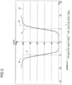
- the function is symmetrical.
- the parameters a and b specify the limits of a desired interval for at least one manipulated variable, at least one process parameter or at least one profile parameter.
- the parameter sh stands for a severity of a secondary condition described by the penalty function in the range of the limits.
- the parameter pn stands for a factor that reflects the importance of the secondary condition.
- sh stands for a slope of the function p_s at the limits a, b and pn for a height to which p_s rises at the limits a, b.
- the desired interval is arranged between the values -5 and 5.
- a penalty for values x that lie outside the desired interval is at a height pn of 100.
- the slope sh is 2.
- Such a penalty function can be used, for example, to specify a desired interval for the vacuum on the calibration device or the crowning of the plastic profile.
- Such a function can be particularly suitable for specifying the largest possible permitted interval for the selection of the at least one control variable, the at least one process parameter or the at least one profile parameter, so that the process window is as large as possible.
- the aim is a minimum profile weight with maximum output, minimum waste and minimum energy consumption.
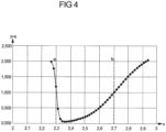
- Fig. 4 shows another version of a penalty function p_a(x).
- the function is asymmetrical.
- the parameters a and b specify the limits of a desired interval of at least one manipulated variable, at least one process parameter or at least one profile parameter.
- the gradient at the limits is different in the present embodiment. Values of x that are below the limit a are thus penalized more severely (i.e. not used in the optimization or taken less into account) than values that are above the limit b. An optimization under such a constraint is therefore more likely to be carried out by specifying values above the limit a.
- Such a constraint can be particularly suitable for the wall thickness or weight per meter of a plastic profile, since the wall thickness and weight per meter must not fall below a certain minimum lower limit, but larger values can generally be acceptable.
- the minimum is close to the lower limit, so that the function can be used to optimize material consumption.
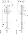
- Fig. 5 shows a view of a pulling device 7 on a calibration device 3 with a winding element 70 on which a flexible traction means 71 designed as a rope can be wound.
- a rigid traction means 72 designed as a rod is arranged on the flexible traction means 71.
- the rod 72 is arranged on a coupling element 73.
- the coupling element 73 is connected to a connecting element 74.
- the connecting element 74 is connected to a plastic profile 10, which is pulled through the calibration device 3 with the pulling device 7.
- Fig. 6 shows a view of a connecting element 74.
- the connecting element 74 comprises two pliers parts that can be connected to one another like pliers, so that a mouth 7410 of the connecting element 74 can be opened by a scissor-like movement of the two pliers parts relative to one another.
- a toothing 740 is arranged on each pliers part on a connecting section 741, which is provided for connection to the plastic profile 10.
- the connecting element 74 also has a coupling section 742, which is provided for connection to the coupling element 73.
- a projection 7421, 7422 is arranged on the coupling section 742 for each pliers part, wherein the projections of the pliers parts adjoin one another when the connecting element 74 is closed.
- Fig. 7 shows a view of a pulling device 7 which is arranged on an extrusion device.
- the pulling device 7 was pushed into a calibration device 3 against an extrusion direction, so that a connection element 74 of the pulling device 7 protrudes from the calibration device 3 for connecting a plastic profile 10 to the pulling device 7.
- Fig. 8 shows a view of a coupling element 73.
- the coupling element 73 has a projection 730 to which the connection element 74 can be fixed.
- two recesses 731 are provided on the coupling element 73, into which wings 751 of a slide-in element 75 can engage.
- at least one recess 731 for the slide-in element 75 can be provided on the coupling element 73.
- Fig. 9 shows a view of an embodiment of an insertion element 75.
- the insertion element 75 is used for connection to the coupling element 73 for easy pushing of the coupling element 73 through the calibration device 3 or another device of the extrusion device against the extrusion direction E.
- the insertion element 75 is removed from the coupling element 73 before the pulling-in process of the plastic profile 10.
- the connection element 74 is then hooked in.
- the insertion element 75 has an engagement 750 into which the projection 730 of the connection element 74 can be inserted. Furthermore, the insertion element 75 has two wings 751 which are intended to engage in recesses 731 on the connection element 74, so that the connection element 74 and the insertion element 75 are positively connected in a direction opposite to the extrusion direction.
- Fig. 10 shows further views of an embodiment of the insertion element 75.
- Fig. 11 shows views of an embodiment of a connection element 74 and an extruded plastic profile 10 to which the connection element 74 can be connected.
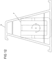
- Fig. 12 shows a cross-section through a calibration device 3 through which a pulling device 7 is pulled.
- Fig. 13 shows a view of an embodiment of a coupling element 73.
- a rigid traction means 72 is arranged on the coupling element 73;
- Fig. 14 shows a schematic representation of a cleaning device 80 with a flat jet nozzle 81. This can be used to generate a jet of cleaning agent in a defined width and direction, which in particular does not affect the still soft surface of the plastic profile 3.
- a cleaning device 80 can be part of a system with which a cleaning agent can be introduced into the calibration device 3 or connected to it (see Fig. 16 ) to remove soft deposits which, over time - depending on the material composition of the extruded plastic profile 10 - accumulate on the steel surface inside the calibration device 3.
- the cleaning device 80 is not only supplied with cleaning agent, but also with signals from the control device 30. This makes it possible to regulate the jet in terms of time and/or quantity, whereby the cleaning agent can comprise a liquid, a gas or a mixture of both. One possible way of controlling this is to apply the cleaning agent at intervals. If the cleaning agent is applied as a thin film, it can penetrate into the gap between the calibration device and the plastic profiles and effect cleaning there.
- Fig. 15 shows a component 82, which can be connected to a calibration device 3, not shown here, with two cleaning devices 80, the upper The cleaning device 80' radiates the cleaning agent upwards, the lower cleaning device 80" radiates to the right.
- the cleaning device 80 is designed here with a flat jet nozzle 81, although in principle other nozzle shapes, e.g. with a circular cross-section, can also be used.
- the emissions of the cleaning agent are in Fig. 16 shown in more detail, wherein two components 82 are provided with a schematically shown calibration device 3 with a total of four cleaning devices 80, which again have flat jet nozzles.
- the components 82 are arranged on both sides of the flow channel for the plastic profile 10.
- the cleaning agent is applied specifically to single-walled profile sections, whereby Fig. 16 accordingly, the contours in the flow channel are shown.
- the single-walled profile sections can also protrude slightly from the plastic profile 10.
- the cleaning agent can be drawn into the gap between the plastic profile 10 and the calibration device 3 (indicated here by a rectangular area) as part of a drag flow.
Landscapes
- Engineering & Computer Science (AREA)
- Mechanical Engineering (AREA)
- Physics & Mathematics (AREA)
- Thermal Sciences (AREA)
- Manufacturing & Machinery (AREA)
- Extrusion Moulding Of Plastics Or The Like (AREA)
- Processing And Handling Of Plastics And Other Materials For Molding In General (AREA)
Description
- Die Erfindung betrifft eine Extrusionsvorrichtung mit den Merkmalen des Anspruchs 1 und ein Extrusionsverfahren mit den Merkmalen des Anspruchs 23.
- Extrusionsvorrichtungen für die Herstellung von Kunststoffprofilen sind grundsätzlich bekannt.
- Die Druckschrift
EP 2 392 446 A1 beschreibt beispielsweise eine aus mehreren Elementen bestehende Extrusionseinrichtung. DieWO 2018/071942 A1 beschreibt ein Verfahren zur Herstellung von Kunststoffprofilen. DieDE 10 2011 007 618 A1 beschreibt eine Extrusionsvorrichtung zur Extrusion von Kunststoffprofilen. Und dieWO 2016/128 829 A1 beschreibt ein Verfahren zur Koextrusion von Polymermaterialien. - Kennzeichnend ist, dass festes Kunststoffmaterial in einem Extruder aufgeschmolzen und anschließend durch eine Extrusionsdüse in Form gebracht wird. Das plastische Kunststoffprofil muss dann unter Einhaltung strenger Qualitätsanforderungen an Maßhaltigkeit und Oberflächengüte verfestigt werden, damit es in einer Ablängvorrichtung zugeschnitten werden kann.
- Das Kunststoffprofil kann beispielsweise ein Hohlkammerprofil sein. Derartige Kunststoffprofile können für die Herstellung von Fensterrahmen vorgesehen sein. Die Extrusionsdüse zur Formung des Kunststoffprofils ist an einem Ausgang des Extruders angeordnet. Nach der Extrusion aus dem Ausgang des Extruders wird das Kunststoffprofil durch eine Kalibriervorrichtung geführt. Der Kalibriervorrichtung ist eine Abzugsvorrichtung nachgeschaltet. Mit der Abzugsvorrichtung kann eine Abzugskraft in das Kunststoffprofil eingeleitet werden, sodass das Kunststoffprofil durch die Kalibriervorrichtung und gegebenenfalls durch weitere Vorrichtungen entlang einer Extrusionsrichtung hindurch gezogen wird. Der Abzugsvorrichtung nachgeschaltet ist eine Ablängvorrichtung zur Abtrennung von Teilen des extrudierten Kunststoffprofils. Beispielsweise kann das Kunststoffprofil mit der Ablängvorrichtung in Abschnitte abgelängt werden.
- Es besteht die Aufgabe, diesen Vorgang wirtschaftlich und qualitativ zu verbessern.
- Die Aufgabe wird durch eine Extrusionsvorrichtung mit den Merkmalen des Anspruchs 1 gelöst.
- Demnach kann eine Profilüberwachungsvorrichtung zur Erfassung mindestens eines Profilparameters des Kunststoffprofils in Extrusionsrichtung nach dem Austreten aus der Extrusionsdüse vorgesehen sein.
- Zusätzlich oder alternativ kann eine Prozessüberwachungsvorrichtung zur Erfassung mindestens eines Prozessparameters im und / oder vor dem Extruder, der Extrusionsdüse, der Kalibriervorrichtung, der Abzugsvorrichtung und / oder der Ablängvorrichtung vorgesehen sein.
- Die Daten der Profilüberwachungsvorrichtung und / oder der Prozessüberwachungsvorrichtung können durch eine Steuervorrichtung dazu verwendbar sein, mindestens eine Stellgröße oder einen Satz von Stellgrößen am Extruder, an der Extrusionsdüse, an der Kalibriervorrichtung, an der Abzugsvorrichtung und / oder an der Ablängvorrichtung in Abhängigkeit von den Daten einzustellen.
- Die Daten können beispielsweise durch die Profilüberwachungsvorrichtung aus dem mindestens einen Profilparameter des Kunststoffprofils erzeugt werden. Ebenso können die Daten durch die Prozessüberwachungsvorrichtung aus dem mindestens einen Prozessparameter erzeugt werden. Die Daten können somit mindestens einen Profilparameter und/oder mindestens einen Prozessparameter umfassen.
- In einer Ausführungsform ist der mindestens eine Profilparameter mindestens eine Wanddicke, insbesondere eine Hauptwandstärke, oder ein Füllgrad des Kunststoffprofils. Das Kunststoffprofil kann eine Wand oder mehrere Wände aufweisen, deren Wanddicken mit der Profilüberwachungsvorrichtung messbar sein können. Entsprechend können mehrere Wanddicken in die durch die Profilüberwachungsvorrichtung erzeugten Daten einfließen. Insbesondere kann der mindestens eine Profilparameter eine Abmessung des Kunststoffprofils, beispielsweise eine Höhe und / oder eine Breite des Kunststoffprofils jeweils quer zur Extrusionsrichtung, sein. Zudem kann der mindestens eine Profilparameter mindestens ein Parameter betreffend einen Schrumpf des Kunststoffprofils sein. Ein Schrumpf kann beispielsweise eine Verkleinerung einer Länge des Kunststoffprofils sein.
- In einer Ausführungsform ist der mindestens eine Profilparameter mindestens ein Parameter betreffend eine Oberflächengüte des Kunststoffprofils. Die Oberflächengüte kann beispielsweise durch optische Eigenschaften der Oberfläche bestimmbar sein. Insbesondere kann die Oberflächengüte durch eine Farbe oder eine Verfärbung der Oberfläche charakterisierbar sein. Die Oberflächengüte kann ebenso durch die Fähigkeit des Kunststoffprofils, Licht ganz oder teilweise zu reflektieren charakterisierbar sein. Insbesondere kann der mindestens eine Parameter einen Glanz oder eine Mattigkeit des Kunststoffprofils betreffen. Der mindestens eine Profilparameter kann ebenso mindestens ein Parameter betreffend eine Streifigkeit des Kunststoffprofils sein. Eine Streifigkeit kann beispielsweise durch Unebenheiten, die in Streifen regelmäßig auftreten, oder streifenartige Verfärbungen gebildet sein.
- In einer Ausführungsform ist der mindestens eine Profilparameter mindestens ein Parameter einer Formabweichung des Kunststoffprofils von einer vorgegebenen Form. Der derartig bestimmte mindestens eine Parameter kann als eine Differenz verstanden werden zwischen der vorgegebenen Form des Kunststoffprofils und der mit der Profilüberwachungsvorrichtung bestimmten Form des Kunststoffprofils. Die Formabweichung kann insbesondere durch einen Krümmungsparameter und/oder einen Winkelparameter bestimmt sein. Der Krümmungsparameter kann beispielsweise angeben, wie konvex oder konkav eine Oberfläche des Kunststoffprofils geformt ist. Die Profilüberwachungsvorrichtung kann dazu eingerichtet sein, zu bestimmen ob ein hohles oder balliges Kunststoffprofil vorliegt. Insbesondere kann der mindestens eine Parameter der Formabweichung des Kunststoffprofils ein Grad einer Bombierung des Kunststoffprofils sein.
- In einer Ausführungsform ist der mindestens eine Profilparameter mindestens eine Temperatur des Kunststoffprofils. Der mindestens eine Profilparameter kann weiterhin ein Metergewicht des Kunststoffprofils, also ein Gewicht des Kunststoffprofils pro Längeneinheit, und/oder eine Oberflächengüte sein.
- Aus dem mindestens einen Profilparameter kann die Profilüberwachungsvorrichtung Daten erzeugen, die beispielsweise eine konkrete Angabe des mindestens einen Profilparameters, beispielsweise "Profilhöhe", und / oder eine gegebenenfalls zugeordnete skalare Größe, beispielsweise "62 mm", umfassen.
- In einer Ausgestaltung ist eine optische Erfassungsvorrichtung für Wanddicken des Kunststoffprofils, für die Oberflächengüte des Kunststoffprofils und / oder die Formabweichung des Kunststoffprofils vorgesehen. In einer derartigen Ausgestaltung kann der mindestens eine Profilparameter mindestens ein Parameter betreffend eine Oberflächengüte des Kunststoffprofils sein. Die Erfassungsvorrichtung für Wanddicken des Kunststoffprofils kann in einer Ausgestaltung die Wanddicken mit Schallwellen oder elektromagnetischer Strahlung erfassen. Insbesondere kann die Erfassungsvorrichtung die Wanddicken des Kunststoffprofils mit Ultraschall- oder Terahertzmessungen bestimmen.
- Im Folgenden werden einige Prozessparameter dargestellt, die alternativ oder zusätzlich zu den Profilparametern verwendet werden können.
- Zunächst kann der mindestens eine Prozessparameter mindestens ein Qualitätsparameter des Kunststoffs selbst sein.
- Der mindestens eine Prozessparameter kann ebenso mindestens ein Geschwindigkeitswert des Kunststoffprofils in der Extrusionsvorrichtung sein. Der mindestens eine Geschwindigkeitswert des Kunststoffprofils in der Extrusionsvorrichtung kann beispielsweise charakterisieren, wie schnell sich das Kunststoffprofil entlang der Extrusionsrichtung fortbewegt.
- In einer Ausführungsform ist der mindestens eine Prozessparameter mindestens eine geometrische Ausrichtung der Kalibriervorrichtung und/oder der Abzugsvorrichtung auf die Extrusionsdüse. Die mindestens eine geometrische Ausrichtung kann beispielsweise einen Winkel und / oder einen Abstand umfassen, in dem die Kalibriervorrichtung und/oder die Abzugsvorrichtung relativ zu der Extrusionsdüse angeordnet sind.
- In einer Ausführungsform ist der mindestens eine Prozessparameter mindestens eine Temperatur und/oder ein Druck im Extruder, in der Extrusionsdüse, in der Kalibriervorrichtung und/oder in der Abzugsvorrichtung. In einer Ausgestaltung ist eine Temperaturmessvorrichtung und/oder eine Druckmessvorrichtung im Extruder, in der Extrusionsdüse, in der Kalibriervorrichtung und/oder in der Abzugsvorrichtung vorgesehen, um dort jeweils die Temperatur und/oder den Druck zu messen.
- In einer Ausführungsform ist der mindestens eine Prozessparameter mindestens eine Kraftmessung an der Abzugsvorrichtung. Der mindestens eine Prozessparameter kann eine Abzugskraft charakterisieren, die die Abzugsvorrichtung auf das Kunststoffprofil ausübt. Ebenso kann der mindestens eine Prozessparameter mindestens eine Messung der Abzugsgeschwindigkeit sein. Der mindestens eine Prozessparameter kann eine Abzugsgeschwindigkeit charakterisieren, mit der sich das Kunststoffprofil durch die Abzugsvorrichtung entlang der Extrusionsrichtung fortbewegt.
- In einer Ausführungsform ist der mindestens eine Prozessparameter mindestens eine Längenmessung an der Ablängvorrichtung. Der mindestens eine Prozessparameter kann eine Länge der Abschnitte des Kunststoffprofils, die an der Ablängvorrichtung erzeugt werden, charakterisieren. Der mindestens eine Prozessparameter kann ebenso mindestens eine Wiegung an der Ablängvorrichtung sein. Für die mindestens eine Wiegung kann der Abschnitt des Kunststoffprofils, der an der Ablängvorrichtung erzeugt wurde, gewogen werden.
- Zudem kann der mindestens eine Prozessparameter eine Belastung eines Antriebs des Extruders sein. Insbesondere kann der mindestens eine Prozessparameter eine Motorbelastung des Extruders sein.
- In einer Ausführungsform ist die mindestens eine Stellgröße ein Fahrparameter der Extrusionsvorrichtung. Die mindestens eine Stellgröße kann beispielsweise eine Stellgröße am Extruder sein. Am Extruder kann die mindestens eine Stellgröße beispielsweise eine Mischungseinstellung mindestens eines dem Extruder zugeführten Kunststoffs sein. Beispielsweise kann die mindestens eine Stellgröße ein Mischverhältnis für unterschiedliche Sorten von Kunststoffen am Extruder sein.
- Die mindestens eine Stellgröße am Extruder kann ebenso eine Temperatur des Extruders sein. Die mindestens eine Stellgröße kann beispielsweise eine Temperatur eines Abschnitts des Extruders, beispielsweise einer Zylindertemperatur, insbesondere vor oder nach einer Entgasung des Extruders, sein. Zudem kann die mindestens eine Stellgröße eine Drehzahl einer oder mehrerer Extrusionsschnecken sein. Die mindestens eine Stellgröße kann insbesondere eine Drehzahl des Antriebs des Extruders sein.
- In einer Ausführungsform ist die mindestens eine Stellgröße an der Extrusionsdüse eine Temperatur. In einer Ausgestaltung ist die Temperatur durch eine Temperiervorrichtung einstellbar. Die Temperatur kann hierbei durch die Temperiervorrichtung lokal auf einen Bereich des Kunststoffprofils einstellbar sein. Ein Bereich des Kunststoffprofils kann beispielsweise ein Bereich an einem Querschnitt des Kunststoffprofils, wie eine Ecke, eine Kante oder eine Gerade sein.
- In einer Ausführungsform ist die mindestens eine Stellgröße ein Fluidstrom. Die mindestens eine Stellgröße kann beispielsweise eine Strömungsgeschwindigkeit oder ein Volumendurchsatz pro Zeiteinheit oder Temperatur des Fluidstroms sein. Der Fluidstrom kann mindestens einen Teil des Kunststoffprofils temperieren. Der mindestens eine Teil des Kunststoffprofils kann beispielsweise ein Bereich an einem Querschnitt des Kunststoffprofils oder ein Bereich, der entlang der Extrusionsrichtung erstreckt ist, sein. Der Fluidstrom kann das Kunststoffprofil oder das mindestens eine Teil des Kunststoffprofils innerhalb der Extrusionsdüse und/oder außerhalb der Extrusionsdüse temperieren. Insbesondere kann der Fluidstrom das Kunststoffprofil oder das mindestens eine Teil des Kunststoffprofils in mindestens einer Werkzeugzone temperieren.
- In einer Ausführungsform ist die mindestens eine Stellgröße eine Temperatur an der Kalibriervorrichtung. Ebenso kann die mindestens eine Stellgröße ein Druck an der Kalibriervorrichtung sein. Die mindestens eine Stellgröße kann ebenso eine Temperatur und ein Druck an der Kalibriervorrichtung sein. Bei der Kalibriervorrichtung kann es sich insbesondere um eine Trockenkalibrierung oder Nasskalibrierung handeln. Ebenso kann es sich bei der Kalibriervorrichtung um eine Trocken- und Nasskalibrierung handeln. Die mindestens eine Stellgröße kann ebenso eine Wasserdurchflussmenge in der Nasskalibrierung sein. Dementsprechend kann die mindestens eine Stellgröße eine Strömungsgeschwindigkeit oder eine Durchflussmenge an Wasser durch die Kalibriervorrichtung pro Zeit sein. Ebenso denkbar und möglich ist es, dass die Kalibriervorrichtung mindestens eine Trockenkalibrierung und/oder mindestens eine Nasskalibrierung umfasst.
- In einer Ausführungsform ist die mindestens eine Stellgröße ein Vakuum an der Kalibriervorrichtung. Insbesondere kann die mindestens eine Stellgröße ein Vakuum an oder ab der mindestens einen Trockenkalibrierung sein. Die mindestens eine Stellgröße kann ebenso ein Vakuum in der Nasskalibrierung sein.
- In einer Ausführungsform ist die mindestens eine Stellgröße an der Kalibriervorrichtung eine Positionsänderung der Kalibriervorrichtung, insbesondere der Trockenkalibriervorrichtung, in Bezug auf die Extrusionsdüse. Beispielsweise kann die mindestens eine Stellgröße an der Kalibriervorrichtung ein Winkel und/oder ein Abstand zwischen der Kalibrierdüse und der Extrusionsdüse sein.
- In einer weiteren Ausführungsform ist die mindestens eine Stellgröße an der Abzugsvorrichtung eine Abzugsgeschwindigkeit und/oder Abzugskraft. Beispielsweise kann die mindestens eine Stellgröße eine Drehzahl eines Antriebs der Abzugsvorrichtung oder eine Klemmkraft, mit der die Abzugsvorrichtung das Kunststoffprofil einklemmt, sein. Grundsätzlich kann die mindestens eine Stellgröße manuell einstellbar sein. Dazu kann eine Bedienperson in Abhängigkeit des mindestens einen Profilparameters und/oder des mindestens einen Prozessparameters die mindestens eine Stellgröße einstellen. Der Bedienperson kann dazu einen Vorschlag für eine Fahrweise der Extrusionsvorrichtung übermittelt werden. Der Vorschlag für die Fahrweise der Extrusionsvorrichtung kann einen Vorschlag für mindestens eine Stellgröße umfassen. Die Bedienperson kann zur Bestimmung des mindestens einen Prozessparameters und/oder des mindestens einen Profilparameters einen Rechner benutzen. Ebenso kann die Bedienperson für die Einstellung der mindestens einen Stellgröße einen Rechner benutzen. Beispielsweise kann der Rechner dazu eingerichtet sein, der Bedienperson anhand des mindestens einen Profilparameters und/oder des mindestens einen Prozessparameters den Vorschlag für die Einstellung der mindestens einen Stellgröße anzuzeigen. Insbesondere kann auf dem Rechner dazu eine Software vorgesehen sein, die ein Assistenzsystem zur Verfügung stellt. In einer Ausgestaltung entnimmt die Bedienperson einen Abschnitt eines Kunststoffprofils als Muster und ermittelt den mindestens einen Prozessparameter und/oder den mindestens einen Profilparameter, insbesondere durch eine Qualitätsvermessung. Die Software kann anhand der Qualitätsvermessung einen Vorschlag für eine optimale Fahrparameteranpassung liefern.
- In einem Beispiel ist der mindestens eine Profilparameter eine Bombierung. Aufgrund der Qualitätsvermessung kann die Bedienperson beispielsweise ermitteln, dass die Bombierung zu konvex ist. Davon ausgehend kann der Bedienperson, insbesondere durch eine Software, als Vorschlag übermittelt werden, das Vakuum in der Kalibriervorrichtung zu verringern, da durch zu hohes Vakuum das Kunststoffprofil überdehnt wird. Alternativ oder zusätzlich kann der Bedienperson als Vorschlag übermittelt werden, den Gesamtausstoß zu senken, beispielsweise, indem die Drehzahl der Extrusionsschnecken sowie optional oder zusätzlich die Abzugsgeschwindigkeit synchron verringert wird. Alternativ oder zusätzlich kann der Bedienperson als Vorschlag übermittelt werden, die Temperatur der Trockenkalibrierung zu senken. Alternativ oder zusätzlich kann der Bedienperson als Vorschlag übermittelt werden, den Wasserdurchfluss der Trockenkalibrierung zu erhöhen.
- In einer Ausführungsform ist der mindestens eine Profilparameter und/oder der mindestens eine Prozessparameter in-line erfassbar. In einer Ausgestaltung bedeutet in-line, dass der mindestens eine Profilparameter und/oder der mindestens eine Prozessparameter direkt an der Extrusionsvorrichtung erfassbar ist. In-line kann zusätzlich auch bedeuten, dass der mindestens eine Profilparameter und/oder der mindestens eine Prozessparameter während des Betriebes der Extrusionsvorrichtung erfassbar ist. Im Gegensatz dazu kann off-line bedeuten, dass der mindestens eine Profilparameter und/oder der mindestens eine Prozessparameter abseits der Extrusionsvorrichtung oder während des Stillstandes der Extrusionsvorrichtung oder abseits der Extrusionsvorrichtung bestimmbar ist. Die Erfassung des mindestens einen Profilparameters und/oder des mindestens einen Prozessparameters off-line kann iterativ in einem vorbestimmten Intervall, insbesondere in einem Intervall von mehreren Stunden, insbesondere drei Stunden, durchgeführt werden.
- Beispielsweise kann durch die optische Erfassungsvorrichtung die Wanddicke des Kunststoffprofils, die Oberflächengüte des Kunststoffprofils und/oder die Formabweichung des Kunststoffprofils in-line bestimmbar sein. Im Gegensatz dazu kann beispielsweise die Wanddicke des Kunststoffprofils durch Vermessen des Kunststoffprofils beispielsweise nach der Entnahme des Kunststoffprofils durch eine Bedienperson off-line bestimmbar sein.
- In einer Ausgestaltung ist der mindestens eine in-line erfasste Profilparameter und/oder der mindestens eine in-line erfasste Prozessparameter durch die Steuervorrichtung automatisch zur Einstellung mindestens eines Steuersignals verwendbar. Insbesondere können die Daten der Profilüberwachungsvorrichtung und/oder der Prozessüberwachungsvorrichtung durch die Steuervorrichtung dazu verwendbar sein, automatisch das mindestens eine Steuersignal in Abhängigkeit von den Daten einzustellen. Das mindestens eine Steuersignal kann beispielsweise mindestens eine Stellgröße am Extruder, an der Extrusionsdüse, an der Kalibriervorrichtung, an der Abzugsvorrichtung und/oder an der Ablängvorrichtung umfassen.
- In einer Ausgestaltung, in der vor dem Extruder mindestens eine vorgeschaltete Vorrichtung angeordnet ist, kann das mindestens eine Steuersignal zusätzlich oder optional mindestens eine Stellgröße der mindestens einen vorgeschalteten Vorrichtung umfassen. Insbesondere kann die mindestens eine Stellgröße daher eine in-line Überwachung einer Schmelzequalität einer Kunststoffschmelze, aus der das Kunststoffprofil im Extruder geformt wird, eine in-line Dry-Blend-Überwachung der Kunststoffschmelze und/oder eine Dosierung durch Gravimetrie der Kunststoffschmelze umfassen.
- Die automatische Einstellung des mindestens einen Steuersignals kann in Abwesenheit einer Bedienperson vorgenommen werden. Die automatische Einstellung kann dadurch ermöglicht werden, dass zwischen dem mindestens einen Profilparameter und dem mindestens einen Steuersignal eine, insbesondere mathematische, numerische oder formelhafte, Beziehung vorgegeben ist. Ebenso kann für den mindestens einen Prozessparameter oder eine Kombination zwischen dem mindestens einen Profilparameter dem mindestens ein Prozessparameter eine Beziehung zu dem mindestens einen Steuersignal vorgegeben sein.
- Das mindestens eine Steuersignal kann in Abhängigkeit des mindestens einen Profilparameters und/oder des mindestens einen Prozessparameters automatisch einstellbar sein. In einer Ausgestaltung wird der mindestens eine Profilparameter und/oder der mindestens eine Prozessparameter in regelmäßigen Abständen an die Steuervorrichtung zur Einstellung des mindestens einen Steuersignals übermittelt. Insbesondere kann eine Vielzahl von Steuersignalen gleichzeitig in Abhängigkeit des mindestens einen Profilparameters und/oder des mindestens einen Prozessparameters automatisch einstellbar sein. Hierbei kann von mindestens einem aktuellen Steuersignal, beispielsweise einem Betriebspunkt der Extrusionsvorrichtung, und mindestens einem aktuellen Prozessparameter und/oder mindestens einem aktuellen Profilparameter, also beispielsweise aktuellen Qualitätswerten der produzierten Kunststoffprofile, ausgegangen werden. Dadurch kann ein Prozessfenster im Betrieb der Extrusionsvorrichtung in Echtzeit maximierbar sein. Das Prozessfenster kann eine Anzahl oder ein Intervall möglicher Werte von mindestens einer Stellgröße, mindestens eines Profilparameters oder mindestens eines Prozessparameters umfassen, die idealerweise für die Optimierung in Betracht gezogen werden sollen. Ein großes Prozessfenster kann einen größeren Spielraum bei mindestens einem Profilparameter ermöglichen, so dass Veränderungen von Prozessparametern leichter kompensiert werden können. Dadurch kann der Ausschuss von Kunststoffprofilen mit unerwünschten Profilparametern minimiert werden.
- In einer Ausführungsform kann die Steuervorrichtung ein Mittel zur Mehrgrößenregelung aufweisen, wobei die erfassten Profilparameter und / oder die erfassten Prozessparameter als Eingangsgrößen dienen.
- Die Steuervorrichtung, beispielsweise eine speicherprogrammierbare Steuerung (SPS), kann zur Einstellung des mindestens einen Steuersignals insbesondere eine Regelschleife aufweisen. Die Regelschleife kann insbesondere multidimensional sein. Ebenso kann es sich um eine intelligente, multidimensionale Regelschleife handeln. Über die Regelschleife kann der mindestens eine Profilparameter und/oder der mindestens eine Prozessparameter als Eingang mit dem mindestens einen Steuersignal als Ausgang verknüpft sein.
- Die Einstellung des mindestens einen Steuersignals in Abhängigkeit der Daten kann eine Änderung des mindestens einen Profilparameters und/oder des mindestens einen Prozessparameters verursachen. Das mindestens eine Steuersignal kann insbesondere solange eingestellt werden, bis mindestens ein gewünschter Profilparameter und/oder mindestens ein gewünschter Prozessparameter erreicht ist. Eine Größe einer Abweichung des mindestens einen aktuellen Profilparameters und/oder des mindestens einen aktuellen Prozessparameters von dem mindestens einen gewünschten Profilparameter und/oder von dem mindestens einen gewünschten Prozessparameter kann dazu verwendet werden, eine Größe der Änderung des mindestens einen Steuersignals bei der Einstellung vorzugeben.
- Unterschiedliche Profilparameter und/oder Prozessparameter können unterschiedlich stark durch die Einstellung des mindestens einen Steuersignals beeinflussbar sein. Daher kann mindestens ein Sensibilitätsfaktor vorgegeben werden, der angibt, wie das mindestens eine Steuersignal mit den Daten der Profilüberwachungsvorrichtung und/oder der Prozessüberwachungsvorrichtung korreliert. Der mindestens eine Sensibilitätsfaktor kann also einen Zusammenhang zwischen dem mindestens einen Steuersignal auf der einen Seite und dem mindestens einen Profilparameter und/oder dem mindestens einen Prozessparameter auf der anderen Seite angeben.
- Der mindestens eine Sensibilitätsfaktor kann manuell, automatisch oder durch Expertenwissen vorgegeben werden. Insbesondere kann der mindestens eine Sensibilitätsfaktor im Betrieb aktualisierbar sein. Beispielsweise kann die Steuervorrichtung dazu eingerichtet sein, aus der Auswirkung einer Änderung des mindestens einen Steuersignals auf den mindestens einen Prozessparameter und/oder den mindestens einen Profilparameter mindestens einen optimierten Sensibilitätsfaktor zu errechnen. Insofern kann die Steuervorrichtung lernfähig sein.
- In einer Ausführungsform weist die Steuervorrichtung ein Mittel zum maschinellen Lernen auf, das automatisch ein Modell, insbesondere für die Mehrgrößenregelung, zur Ermittlung der Zusammenhänge zwischen dem mindestens einen Profilparameter, dem mindestens einen Prozessparameter und der mindestens einen Stellgröße ermittelt. Insbesondere kann das Mittel zum maschinellen Lernen den mindestens einen Sensibilitätsfaktor ermitteln.
- Der mindestens eine Sensibilitätsfaktor kann beispielsweise über das folgende Verfahren ermittelbar sein: In einem ersten Schritt wird die Extrusionsvorrichtung am Betriebspunkt mit einem ersten Wert der mindestens einen Stellgröße betrieben und ein erster Satz Daten der Profilüberwachungsvorrichtung und/oder der Prozessüberwachungsvorrichtung gesammelt. In einem zweiten Schritt wird die Extrusionsvorrichtung mit einem zweiten Wert der mindestens einen Stellgröße betrieben, der sich von dem ersten Wert unterscheidet, und ein zweiter Satz Daten der Profilüberwachungsvorrichtung und/oder der Prozessüberwachungsvorrichtung gesammelt. Gegebenenfalls wird der zweite Schritt mehrmals wiederholt, wobei der zweite Wert über oder unter dem ersten Wert sein kann und insbesondere regelbasiert variiert wird. In einem dritten Schritt wird aus dem ersten Satz und dem mindestens einen zweiten Satz Daten ein Zusammenhang zwischen der mindestens einen Stellgröße und den Daten bestimmt. Der Zusammenhang kann eine Stärke einer Korrelation zwischen der mindestens einen Stellgröße und dem mindestens einen Prozessparameter und/oder dem mindestens einen Profilparameter umfassen.
- Der Zusammenhang kann beispielsweise durch eine Koeffizientenmatrix ausgedrückt werden, die jeder Kombination von der mindestens einen Stellgröße mit dem mindestens einen Profilparameter und/oder dem mindestens einen Prozessparameter eine Korrelationsstärke zuordnet. Beispielsweise kann die Ausstoßleistung des Extruders bei konstantem Profilgewicht positiv mit der Bombierung korrelieren, während die Abzugsgeschwindigkeit negativ mit der Bombierung und kaum mit der Belastung des Antriebs des Extruders korreliert.
- Der mindestens eine Sensibilitätsfaktor kann also eine Koeffizientenmatrix sein, die angibt, wie sich der mindestens eine Prozessparameter und/oder der mindestens eine Profilparameter, also insbesondere die Qualität des Kunststoffprofils, ändert, sobald die mindestens eine Stellgröße, also insbesondere ein Fahrparameter, geändert wird.
- Durch das Mittel zum maschinellen Lernen kann der mindestens eine Sensibilitätsfaktor im Betrieb der Extrusionsvorrichtung weiter anpassbar sein, um genauer vorhersagen zu können, wie sich der mindestens eine Prozessparameter und/oder der mindestens eine Profilparameter ändert, sobald die mindestens eine Stellgröße geändert wird.
- In einer Ausführungsform ist ein Simulationssystem vorgesehen, mit dem eine Auswirkung einer Änderung des mindestens einen Steuersignals auf den mindestens einen Profilparameter und/oder den mindestens einen Prozessparameter simulierbar ist. Das Simulationssystem kann dazu eingerichtet sein, den mindestens einen Sensibilitätsfaktor durch eine Simulation zu bestimmen und an die Steuervorrichtung zu übermitteln.
- In einer Ausführungsform ist die Steuervorrichtung dazu eingerichtet, im Betrieb unter Nutzung des mindestens einen Sensibilitätsfaktors die mindestens eine Stellgröße zu bestimmen, um mindestens einen gewünschten Profilparameter und/oder mindestens einen gewünschten Prozessparameter zu erreichen. Die mindestens eine Stellgröße kann insbesondere aus mindestens einer aktuellen Stellgröße, insbesondere aktuellen Fahrparametern, und aus dem mindestens einen Profilparameter und/oder dem mindestens einen Prozessparameter, insbesondere aktuellen Qualitätswerten, bestimmbar sein. Es können also optimierte Fahrparameter, die optimierte Qualitätswerte hervorbringen, aus aktuellen Fahrparametern und aktuellen Qualitätswerten auf Grundlage eines Wissens über den Zusammenhang zwischen einer Fahrparameteränderung und einer Änderung der Qualitätswerte bestimmt werden.
- In einer Ausgestaltung ist die Steuervorrichtung dazu eingerichtet, ein gewünschtes Intervall für den mindestens einen Profilparameter und/oder den mindestens einen Prozessparameter vorzugeben. Die Steuervorrichtung weist ein Mittel zur Durchführung einer mathematischen Optimierung eines Satzes von Stellgrößen unter mindestens einer Nebenbedingung bezüglich eines Wertes des mindestens einen Profilparameters, des mindestens einen Prozessparameters und/oder der mindestens einen Stellgröße des Satzes von Stellgrößen auf. Die mindestens eine Nebenbedingung ist als eine Penalty-Funktion ausdrückbar.
- Die Steuervorrichtung kann eine mathematische Optimierung der mindestens einen Stellgröße oder eines Satzes von Stellgrößen beispielsweise unter der Bedingung vornehmen, dass der mindestens eine Profilparameter, der mindestens eine Prozessparameter, mindestens eine weitere Stellgröße und/oder mindestens eine Stellgröße des Satzes von Stellgrößen in einem gewünschten Intervall liegt.
- Bei Optimierung eines Satzes von Stellgrößen mit mindestens einer Stellgröße und mindestens einer weiteren Stellgröße soll beispielsweise die mindestens eine weitere Stellgröße in einem gewünschten Intervall liegen. Die mindestens eine weitere Stellgröße kann dann mit einer 1 zu 1 Beziehung zu sich selbst in die Optimierung einbezogen werden.
- Grundsätzlich kann die Beziehung zwischen der zu optimierenden mindestens einen Stellgröße und dem mindestens einen Profilparameter und/oder dem mindestens einen Prozessparameter durch den mindestens einen Sensibilitätsfaktor vorgegeben sein.
- Die Steuervorrichtung kann zur mathematischen Optimierung ein Verfahren zur Optimierung mit mindestens einer Nebenbedingung verwenden. Die Nebenbedingung kann beispielsweise als Penalty-Funktion vorgegeben werden. Die Penalty-Funktion kann symmetrisch sein. Beispielsweise zur Integration von Gewichts- und/oder Wandstärkenoptimierung des Kunststoffprofils kann die Penalty-Funktion ebenso asymmetrisch sein. Die Penalty-Funktion kann beispielsweise eine Sigmoidfunktion, insbesondere die Funktion p_a(x)=1/(1+e^-x) beinhalten.
- In einer Ausführung ist eine Reinigungsvorrichtung vorgesehen, die dazu eingerichtet ist, ein Reinigungsmittel in die Kalibriervorrichtung einzubringen, um insbesondere weiche Ablagerungen zu entfernen, die sich mit der Zeit - abhängig von der Materialzusammensetzung des extrudierten Kunststoffprofils - an der Stahloberfläche im Inneren der Kalibriervorrichtung ansammeln. Diese Ablagerungen führen mit zunehmender Produktionsdauer zu einer Verschlechterung der Oberflächenqualität des extrudierten Kunststoffprofils, stören aber auch den Extrusionsprozess an sich, beispielsweise durch ein Klebenbleiben des Kunststoffprofils an der Ablagerung und somit Hängenbleiben bestimmter Profilsektionen, wodurch Ausschuss und Produktionsstillstände verursacht werden.
- Die Reinigungsvorrichtung kann beispielsweise durch die Steuervorrichtung gesteuert werden, insbesondere kann sie zeitlich und mengenmäßig automatisch geregelt und / oder von einem Bediener manuell gesteuert werden. Das Reinigungsmittel kann automatisch und/oder in vordefinierten Abständen eingebracht werden. Das Reinigungsmittel kann flüssig oder gasförmig sein.
- Das Reinigungsmittel kann z.B. auf das Kunststoffprofil aufgesprüht werden, wobei es sich dann in den Spalt zwischen Kalibriervorrichtung und Kunststoffprofil hineinzieht. Es kann aber auch auf Kalibriervorrichtung und/oder in einen Fließkanal eingebracht werden.
- Durch die Bewegung des Kunststoffprofils in Extrusionsrichtung wird das Reinigungsmittel in die Kalibriervorrichtung eingebracht/eingezogen und reinigt dort die Stahloberfläche im Inneren der Kalibriervorrichtung.
- Die Reinigungsvorrichtung kann in einer Ausführungsform mindestens eine Flachstrahldüse aufweisen, mit der geringe Mengen an Reinigungsmittel mit wenig Druck fein zerstäubt werden, so dass kein Schaden am Kunststoffprofil und somit auch kein Ausschuss während des Reinigungsvorganges entsteht.
- Eine möglichst flache Ausführung der Flachstrahldüse ermöglicht eine flexible Platzierung in dem engen Spalt zwischen Düse und Kalibriervorrichtung. Eine Abschrägung am Sprühdüsenausgang lenkt den Sprühstrahl in Richtung der Kalibriervorrichtung, nicht aber in Richtung der Düse, um eine negative Beeinflussung dieser zu vermeiden. Das Sprühen ermöglicht ein Aufbringen des Reinigungsmittels auf das Kunststoffprofil aus allen Winkeln (von unten/von oben/von der Seite). Die Reinigungsvorrichtung kann verschraubt und/oder magnetisch an der Kalibriervorrichtung befestigt werden. Die Reinigungsvorrichtung kann auch direkt in der Kalibrierung integriert sein.
- In einer Ausgestaltung wird auf ein Signal von der Steuereinheit hin eine automatische Reinigung der Vorrichtungen, insbesondere der Kalibriervorrichtungen durchgeführt. Ebenso kann die Belagsmesseinrichtung mit der Reinigungsvorrichtung gekoppelt sein, um eine Reinigung der Vorrichtung, insbesondere der Kalibriervorrichtungen oder von Werkzeugen der Extrusionsvorrichtung in Abhängigkeit eines gemessenen Grades an Verschmutzung auszulösen.
- Die Reinigungsvorrichtung kann das Reinigungsmittel aufbringen oder auftragen, insbesondere aufsprühen.
- Insbesondere kann das Reinigungsmittel als dünner Film auf die Oberfläche des Kunststoffprofils aufgebracht werden, insbesondere mittels Schlitzen oder Taschen in der Kalibriervorrichtung, so dass das Reinigungsmittel durch Schleppströmung vom Kunststoffprofil mittransportierbar ist. Damit kann eine effiziente Reinigung erreicht werden.
- Wie erwähnt, kann das Reinigungsmittel z.B. mit einer Düse wie einer Flachstrahldüse aufgebracht werden. Es ist aber alternativ oder zusätzlich auch möglich, dass das Reinigungsmittel der Reinigungsvorrichtung durch eine poröse Oberfläche, insbesondere durch einen porösen Sintereinsatz in der Kalibriervorrichtung auf das Kunststoffprofil aufbringbar ist.
- Dabei kann es sinnvoll sein, dass das Reinigungsmittel gezielt auf eine einwandige, insbesondere abstehende Profilsektion des Kunststoffprofils oder den gesamten Profilumfang abgebbar ist.
- Eine verbesserte Reinigungswirkung kann erreicht werden, wenn das Reinigungsmittel intervallweise aufbringbar ist. Die Steuerungsvorrichtung kann die Intervallzeiten und die Mengen steuern.
- Des Weiteren wird die Aufgabe durch ein Verfahren mit den Merkmalen des Anspruchs 23 gelöst.
- Die Aufgabe wird auch durch eine Einziehvorrichtung gelöst. Zum Anfahren eines neuen Kunststoffprofils kann die Einziehvorrichtung entgegen der Extrusionsrichtung in eine Extrusionsvorrichtung eingeschoben werden. Die Einziehvorrichtung kann mindestens ein Zugmittel wie eine gegebenenfalls kraftoptimierte Einziehstange, einen Einziehgurt, ein Federstahlband und/oder ein Seil aufweisen. Insbesondere sind Kombinationen von Zugmitteln denkbar und möglich. Das Verwenden des mindestens einen Zugmittels ermöglicht ein Einleiten einer Zugkraft in das Kunststoffprofil bereits beim Austreten aus einer Extrusionsdüse der Extrusionsvorrichtung. Die Zugkraft zum Kalibrieren kann somit sofort aufgenommen werden. Die Einziehvorrichtung kann ein Anschlusselement zum Anschluss an das Kunststoffprofil aufweisen. Das Kunststoffprofil kann nach dem Austritt aus der Extrusionsdüse mit dem Anschlusselement verbunden werden. Das Anschlusselement kann über ein Kopplungselement mit dem mindestens einen Zugmittel verbunden sein. Insbesondere kann das Anschlusselement eine Klemmvorrichtung sein. Das Anschlusselement kann von dem Kopplungselement abnehmbar oder entkoppelbar sein. Nach dem Verbinden des Anschlusselements mit dem Kunststoffprofil kann der Anfahrprozess gestartet werden. Mit der Einziehvorrichtung kann das Kunststoffprofil durch die gesamte Extrusionsvorrichtung, insbesondere umfassend eine Kalibriervorrichtung, eine Abzugsvorrichtung sowie eine Ablängvorrichtung, gezogen werden.
- Das Anschlusselement kann dazu ausgebildet sein, das Kunststoffprofil zu kühlen. Das Anschlusselement kann beispielsweise metallisch sein, um das Kunststoffprofil ausreichend vorzukühlen. Insbesondere kann das Anschlusselement aus Aluminium oder Messing gefertigt sein. Das Anschlusselement kann durch ein 3D-Druckverfahren hergestellt werden.
- Das Anschlusselement kann einen Anschlussabschnitt zum Verbinden mit dem Kunststoffprofil aufweisen. Das Anschlusselement kann mit dem Kunststoffprofil formschlüssig und/oder kraftschlüssig verbunden sein. Beispielsweise kann das Anschlusselement eine Verzahnung aufweisen, die formschlüssig in das Kunststoffprofil eingreift. Insbesondere kann das Anschlusselement zangenartig ausgebildet sein. Das Kunststoffprofil kann in einem Maul des Anschlusselements formschlüssig und/oder kraftschlüssig festgelegt sein. Die Verzahnung kann an dem Maul angeordnet sein. In einer Ausgestaltung ist die Verzahnung schräg zur Extrusionsrichtung angeordnet, so dass die Verzahnung das Kunststoffprofil in Zugrichtung fixiert. Wenn keine Zugkraft anliegt, kann das Anschlusselement durch einfache Öffnung des Mauls von dem Kunststoffprofil ablösbar sein. Insbesondere kann das Maul zwei Klemmbacken aufweisen, zwischen denen das Kunststoffprofil einklemmbar ist.
- Das Anschlusselement kann weiterhin einen Kopplungsabschnitt zur Verbindung mit dem Kopplungselement aufweisen. Der Kopplungsabschnitt kann zur form- und/oder kraftschlüssigen Verbindung dem Kopplungselement ausgebildet sein. Insbesondere kann der Kopplungsabschnitt zwei Zangengriffe, die zur Betätigung der Klemmbacken an dem Anschlusselement vorgesehen sind, aufweisen. Vorsprünge an den Zangengriffen können in einer geschlossenen Stellung, in der das Kunststoffprofil mit den Klemmbacken einklemmbar ist, zur Ausbildung einer Ausnehmung aneinander anliegen. Das Kopplungselement kann einen Vorsprung aufweisen, an dem die Ausnehmung zur formschlüssigen Verbindung festlegbar ist. In einer offenen Stellung des Anschlusselements können die Vorsprünge getrennt sein, so dass das Anschlusselement nur in einer geschlossenen Stellung mit dem Kopplungselement verbindbar ist.
- Das mindestens eine Zugelement kann an einem Wickelelement gewickelt oder einer Aufrollvorrichtung der Einziehvorrichtung gerollt werden, um das Kunststoffprofil durch die Extrusionsvorrichtung zu ziehen.
- Im Folgenden wird ein automatisierter Anfahrprozess beschrieben. Nach dem Abbauen eines Extrusionswerkzeuges und Wiederaufbauen eines neuen Werkzeuges auf einer Extrusionslinie ist nicht unbedingt sichergestellt, dass eine Relativposition zwischen Extrusionsdüse und Trockenkalibrierung ausreichend genau reproduziert werden kann. Eine Positioniereinrichtung kann vorgesehen sein, um eine, insbesondere automatische, exakte und reproduzierbare, Ermittlung und/oder Herstellung der Relativposition zwischen Extrusionsdüse und Kalibriervorrichtung zu ermöglichen. Die Positioniereinrichtung kann eine mechanische Einrichtung sein. Die Positionierung kann insbesondere mittels Sensoren erfolgen. Beispielsweise kann die Positioniereinrichtung mindestens einen Sensor umfassen. Die Positioniereinrichtung kann beispielsweise einen Taststift, einen Tastkegel und/oder Lasermesstechnik aufweisen. Weitere Sensoren können den richtigen Aufbau der Extrusionsdüse und / oder der Trockenkalibrierung detektieren und gegebenenfalls melden.
- In einer Ausgestaltung wird der mindestens eine Prozessparameter für den Anfahrprozess automatisch eingestellt. Der mindestens eine Prozessparameter kann insbesondere eines oder mehrere von einem Vakuum in der Nasskalibrierung, einer Geschwindigkeit in der Abzugsvorrichtung, einem Anpressdruck in der Abzugsvorrichtung, einer Drehzahl der Extrusionsschnecken und/oder eine Temperatur in der Kalibriervorrichtung sein.
- Mittels eines Profilvermessungssystems kann eine Position von Innenstegen des Kunststoffprofils gemessen werden. Das Profilvermessungssystem kann zwischen der Nasskalibrierung und der Abzugsvorrichtung oder (zusätzlich oder optional) stromabwärts der Abzugsvorrichtung angeordnet sein. Es an dem Profilvermessungssystem können Sensoren und/oder Ventile vorgesehen sein, die eine Stützluft in der Extrusionsdüse regeln. Definierte Luftvolumenströme können in bestimmte Profilhohlkammern eingeblasen werden, um insbesondere beim Anfahren Innenstege, die verklebt sind, zu lösen und / oder um in-line eine Maßhaltigkeit eines Innenlebens des Kunststoffprofils zu gewährleisten.
- Sobald sich der mindestens eine Profilparameter und/oder der mindestens eine Prozessparameter, insbesondere alle Profil- und Prozessparameter, innerhalb einer vorgegebenen Toleranz befinden und/oder das Profil als gut bewertet wird, kann automatisch oder über ein Signal von einem Bediener eine virtuelle Profilmarkierung über die Steuervorrichtung gesetzt und beispielsweise über ein Display der Steuervorrichtung zum Anzeigen von Informationen visualisiert werden. Mittels der Ablängvorrichtung wird an dieser Stelle automatisch ein Profilmuster von dem Kunststoffprofil abgesägt. Über die Abzugsgeschwindigkeit kann berechnet werden, wann diese virtuelle Profilmarkierung die Ablängvorrichtung erreicht. Die virtuelle Profilmarkierung kann beispielsweise eine Zeit t umfassen, die das markierte Profil bis zur Ablängvorrichtung zurücklegt. Die Zeit t kann über eine Abzugsgeschwindigkeit v_a, mit der das Kunststoffprofil durch die Extrusionsvorrichtung gezogen wird, und einer bekannten Strecke s_b, die das Kunststoffprofil vom Setzen der virtuellen Profilmarkierung bis zur Ablängvorrichtung zurücklegt mit Hilfe der Formel t = s_b/v_a berechnet werden. Der Anfahrprozess kann mit dem Absägen des Profilmusters enden. Danach kann die Produktion aufgenommen werden.
- In einer Ausgestaltung ist eine Kraftmesseinrichtung in der Abzugsvorrichtung vorgesehen, die die Abzugskraft misst und/oder ein Rutschen des Kunststoffprofils in der Abzugsvorrichtung erkennt. Die Kraftmesseinrichtung kann dazu eingerichtet sein, den Anpressdruck entsprechend anzupassen. In einer Variante ist die Kraftmesseinrichtung mit der Steuervorrichtung gekoppelt, um die gemessenen Werte der Abzugskraft und/oder einen Rutschwert an die Steuervorrichtung zu übermitteln. Die Steuervorrichtung kann dazu eingerichtet sein, den Anpressdruck auf Basis eine vorgegebenen oder mittels Messeinrichtung in-line gemessenen Reibungskoeffizienten und der gemessenen Abzugskraft entsprechend anzupassen.
- In einer Ausgestaltung ist eine Belagsmesseinrichtung innerhalb der Kalibriervorrichtung, vorgesehen, die dazu eingerichtet ist, Beläge zu erkennen, die durch den Abrieb von Extrudat und / oder in Wechselwirkung mit der Umgebung (Wasser / Luft) an der Kalibrierung anhaften. In einer Variante ist die Belagsmesseinrichtung mit der Steuervorrichtung gekoppelt, um einen gemessenen Grad an Belägen an die Steuervorrichtung zu übermitteln.
- Anhand von beispielhaften Ausführungsformen werden die Überwachungsvorrichtung und das Überwachungssystem anhand von Figuren beschrieben. Dabei zeigt
- Fig. 1
- eine schematische Darstellung einer Extrusionsvorrichtung mit einer Steuervorrichtung;
- Fig. 2A und 2B
- Schnittansichten einer Kalibriervorrichtung;
- Fig. 3
- grafische Darstellung einer symmetrischen Penalty-Funktion;
- Fig. 4
- grafische Darstellung einer asymmetrischen Penalty-Funktion;
- Fig. 5
- eine Ansicht einer Einziehvorrichtung;
- Fig. 6
- eine Ansicht eines Anschlusselements;
- Fig. 7
- eine Ansicht einer Einziehvorrichtung, die an einer Extrusionsvorrichtung angeordnet ist;
- Fig. 8
- eine Ansicht eines Kopplungselements;
- Fig. 9
- Ansicht einer Ausgestaltung eines Einschiebelements;
- Fig. 10
- Ansichten einer Ausgestaltung eines Einschiebelements;
- Fig. 11
- Ansichten einer Ausgestaltung eines Anschlusselements;
- Fig. 12
- Querschnitt durch eine Kalibriervorrichtung, durch die eine Einziehvorrichtung gezogen wird; und
- Fig. 13
- eine Ansicht einer Ausgestaltung eines Kopplungselements;
- Fig. 14
- zeigt eine schematische Darstellung einer Reinigungsvorrichtung mit einer Flaschstrahldüse;
- Fig. 15
- zeigt ein Bauelement mit zwei Reinigungsvorrichtungen;
- Fig. 16
- zeigt eine Schnittansicht mit zwei Bauelementen mit vier Reinigungsvorrichtungen.
- In
Fig. 1 ist der schematische Aufbau einer an sich bekannten Extrusionsvorrichtung dargestellt, wobei die Extrusionsrichtung E hier von links nach rechts verläuft. - Aus einem Extruder 1wird eine homogene Schmelze in einer einstellbaren Menge mit der nötigen Temperatur in die nachfolgende Extrusionsdüse 2 gefördert. Im Extruder wird z.B. Kunststoffgranulat (ein oder auch mehrere Kunststoffsorten) aufgeschmolzen, wobei die plastische, hoch-viskose Kunststoffschmelze durch Extruderschnecken in Richtung Extrusionsdüse 2 gefördert wird.
- Die Extrusionsdüse 2 formt die unter Druck angelieferte homogene Kunststoffschmelze zu der gewünschten Querschnittsform, nämlich einem Kunststoffprofil, insbesondere einem Hohlkammerprofil. In und / oder an der Extrusionsdüse können Temperiervorrichtungen vorgesehen sein, mit denen z.B. das fertige Kunststoffprofil nach dem Austreten aus der Extrusionsdüse 2 gekühlt werden kann. Auch ist es möglich, dass im Inneren der Extrusionsdüse eine Temperiervorrichtung das sich formende Kunststoffprofil kühlt und / oder aufheizt.
- Eine Kalibriervorrichtung 3 nimmt das aus der der Extrusionsdüse 2 kommende, noch thermoplastisch verformbare Kunststoffprofil 10 auf und fixiert es durch Abkühlung auf die gewünschten Abmessungen.
- Die Abkühlung erfolgt in der Kalibriervorrichtung 3 in einer Nasskalibrierung und / oder einer Trockenkalibrierung. Bei der Nasskalibrierung wird Wärmeenergie durch Wasser abgeführt, das mit dem Kunststoffprofil 10 in Kontakt gebracht wird.
- Eine Abzugsvorrichtung 4 ist der Kalibriervorrichtung 3 nachgeschaltet, wobei dabei typischerweise das Kunststoffprofil 10 durch einen Raupenabzug gezogen wird.
- Nach der Abzugsvorrichtung 4 ist in Extrusionsrichtung E eine Ablängvorrichtung 5 angeordnet, in der das kontinuierlich erzeugte Kunststoffprofil 10 z.B. mit einer Säge, auf ein vorgegebenes Maß zugeschnitten wird.
- Eine Verwiegevorrichtung 6, die der Ablängvorrichtung 5 nachgeschaltet ist, ermöglicht, dass jede einzelne Profilstange im laufenden Extrusionsprozess verwogen wird.
- Das Ergebnis soll regelmäßig ein Kunststoffprofil 10 sein, dessen Materialeigenschaften, dessen Oberfläche und dessen innere und äußere Maßhaltigkeit vorgegebene Anforderungen erfüllen müssen.
- Im Folgenden werden Ausführungsformen für eine Steuerung oder Regelung beschrieben, die dies gewährleisten können.
- Eine Profilüberwachungsvorrichtung 20 dient dabei der Erfassung mindestens eines Profilparameters des Kunststoffprofils 10 nach dem Austreten aus der Extrusionsdüse 2. Dies bedeutet dass eine Eigenschaft des Kunststoffprofils 10 auf dem Weg zwischen Extrusionsdüse 2, der Kalibriervorrichtung 3, der Abzugsvorrichtung 4, der Ablängvorrichtung 5, der Verwiegevorrichtung 6 und / oder in mindestens einer der jeweiligen Vorrichtungen 3, 4, 5, 6erfasst wird. Dazu können z.B. Sensoren dienen, die auf die entsprechende Eigenschaft des Kunststoffprofils 10 ausgerichtet sind.
- Neben mindestens einem Profilparameter wird durch eine Prozessüberwachungsvorrichtung 21 zusätzlich oder alternativ noch mindestens ein Prozessparameter im und / oder vor dem Extruder1, der Extrusionsdüse 2, der Kalibriervorrichtung 3, der Abzugsvorrichtung 4, der Ablängvorrichtung 5 und / oder der Verwiegevorrichtung 6 erfasst. Die Erfassung kann dabei ebenso in den Vorrichtungen 1, 2, 3, 4, 5, 6 und / oder auf dem Weg des Kunststoffprofils zwischen den Vorrichtungen 1, 2, 3, 4, 5, 6 erfolgen.
- Die Profilüberwachungsvorrichtung 20 und die Prozessüberwachungsvorrichtung 21 sind hier getrennt dargestellt, wobei diese auch auf einem Rechner integriert sein können.
- Die Daten Profilüberwachungsvorrichtung 20 und / oder der Prozessüberwachungsvorrichtung 21 werden dann durch eine Steuervorrichtung 30 dazu verwendet, mindestens eine Stellgröße S1, S2, S3, S3, S4, S5, S6 am Extruder 1, an der Extrusionsdüse 2, an der Kalibriervorrichtung 3, an der Abzugsvorrichtung 4 ,an der Ablängvorrichtung 5 und / oder an der Verwiegevorrichtung 6 in Abhängigkeit von den Daten einzustellen.
- Somit liegt hier eine Struktur einer Mehrgrößenregelung vor, bei der die Eingangsdaten von im Kunststoffprofil 10 und / oder von den Einheiten 1, 2, 3, 4, 5, 6 der Extrusionsvorrichtung gewonnen werden. Dabei ist es nicht zwingend, dass immer alle Eingangs- und Ausgangsgrößen miteinander verknüpft werden.
- Die Steuervorrichtung 30 verfügt über ein Mittel, mit dem Eingangsdaten in Stellgrößen S1, S2, S3, S4, S5, S6 umgerechnet werden. Dieses Mittel kann z.B. ein Regelgesetz (z.B. ein PID-Regler, ein modellbasierter Regler) sein, das einen Eingang mit einem Ausgang, d.h. einer Stellgröße S1, S2, S3, S4, S5, S6 fest verknüpft. Das Mittel kann aber auch ein komplexeres Modell aufweisen, bei dem viele Eingänge mit vielen Ausgängen, d.h. Stellgrößen S1, S2, S3, S4, S5, S6 verknüpft. Eine solches Modell kann als Rechenmodell vorgegeben werden und / oder in Form eines selbstlernenden Modells, z.B. im Rahmen des maschinellen Lernens.
- Im Folgenden wird zunächst auf einige Profilparameter eingegangen. So kann z.B. mit einem optischen Sensor (z.B. einer Kamera und einer Bildverarbeitung) eine Wanddicke des Kunststoffprofils erfasst werden. Die Wanddicke kann dabei eine Außenwandung als auch die Wandung einer Hohlkammer sein.
- Ebenfalls mit einem optischen Sensor kann mindestens ein Parameter betreffend die Oberflächengüte, insbesondere die Farbe, den Glanz, die Streifigkeit, die Rauigkeit und / oder der Glanz ermittelt werden. Dies kann z.B. jeweils zwischen den Einheiten 1, 2 3, 4, 5, 6 erfolgen, da hier das Kunststoffprofil 10 gut zugänglich ist.
- Mit einem Sensor, z.B. einer Kamera kann mindestens ein Parameter der Formabweichung des Kunststoffprofils 10 von einer vorgegebenen Form erfasst werden. Z.B. mit einer Bildverarbeitung kann insbesondere ein Krümmungsparameter und / oder ein Winkelparameter ermittelt werden, der die Abweichung von einer Norm darstellt.
- Mit einem Infrarotsender kann auch noch mindestens eine Temperatur des Kunststoffprofils 10 ermittelt werden, wobei aus Gründen der Zugänglichkeit, auch diese Messung sinnvollerweise zwischen den Einheiten 1, 2, 3, 4, 5, 6 erfolgt.
- Im Folgenden werden einige Prozessparameter dargestellt, die alternativ oder zusätzlich zu den Profilparametern verwendet werden können.
- Die Geschwindigkeit des Kunststoffprofils 10 wird durch die Abzugsgeschwindigkeit der Abzugsvorrichtung 4 bestimmt.
- Ein Kamerasystem oder ein anderer optischer Sensor kann auch dazu verwendet werden, um mindestens eine korrekte geometrische Ausrichtung der Kalibriervorrichtung 3 und / oder der Abzugsvorrichtung 5 auf die Extrusionsdüse 2sicherzustellen. Wenn z.B. die Zentrierung des Kunststoffprofils 10 vom Normwert abweicht, führt dies z.B. zu Verbiegungen, Verdrehungen und Spannungen im Material
- Für eine richtige Abkühlung, insbesondere in der Kalibriervorrichtung 4, kann z.B. mindestens ein Temperaturwert und / oder ein Druckwert im Extruder 4, in der Extrusionsdüse 2, in der Kalibriervorrichtung 3 und / oder in der Abzugsvorrichtung 4 gemessen werden, da sich entlang des Extrusionsprofils 10 in der Regel ein vorbestimmtes Temperaturprofil einstellen soll.
- An der Abzugsvorrichtung 4 kann z.B. die Abzugskraft, ein Schlupf und / oder die Abzugsgeschwindigkeit gemessen werden, da diese Parameter einen Einfluss auf das gesamte Kunststoffprofil 10 haben.
- Parameter, die an der Ablängvorrichtung 5 erfasst werden können, sind die Längen und / oder die Masse der abgetrennten Kunststoffprofile 10.
- An der Verwiegevorrichtung 6 kann das Gewicht der abgelängten Profilstangen ermittelt werden.
- Somit weist die Ausführungsform eine Fülle von Parametern auf, die als Eingangsgrößen für die Steuervorrichtung 30 dienen können. Dabei ist zu beachten, dass natürlich nicht in jedem Fall alle der Eingangsgrößen gleichzeitig gemessen werden müssen. Es können Teilmengen der Profilparameter und / oder der Prozessparameter verwendet werden.
- In der Steuervorrichtung 30 können diese Eingangswerte dann zur Bestimmung von Stellgrößen S1, S2, S3, S4, S5, S6 verwendet werden. Auch hier ist es nicht zwingend, dass alle möglichen Stellgrößen S1, S2, S3, S4, S5, S6 verwendet werden.
- Im Folgenden werden einige Stellgrößen näher beschrieben. Eine Stellgröße am Extruder 1 ist die Mischungseinstellung des dem Extruder 1 zugeführten Kunststoffs. Diese Stellgröße S1 kann z.B. dazu verwendet werden festgestellte Abweichungen in der Kunststoffqualität und / der Farbe auszugleichen. Auch die Temperatur und / oder die Drehzahl der Extrusionsschnecken im Extruder haben Einfluss auf die Art des auszubildenden Kunststoffprofils 10.
- Für die Extrusionsdüse 2 kann z.B. mindestens eine Temperatur eine sinnvolle Stellgröße S2 sein. Dabei ist nicht zwangsläufig eine gemittelte Temperatur über die Extrusionsdüse 2 oder den Querschnitt des Kunststoffprofils 10 gemeint. Vielmehr können mit geeigneten Temperiervorrichtungen an und / oder in der Extrusionsdüse 2 gezielt Teile des Kunststoffprofils 10 beeinflusst werden. Die Temperatur in der Extrusionsdüse 2 hat einen Einfluss auf die Viskosität des Kunststoffes und damit auf die Fließgeschwindigkeit.
- In der Kalibriervorrichtung gibt es eine Reihe von Stellgrößen S3, die Einfluss auf ein thermisches Verhalten haben. So kann z.B. die Temperatur und / oder der Wasserdurchfluss an einer oder mehreren Stellen geregelt werden. Die Verwendung des Druckes als Stellgröße S3 hat Einfluss auf die Form des Kunststoffprofils 10. Es ist aber auch möglich geometrische Parameter mit Stellgrößen S3 einzustellen, indem z.B. die mindestens eine Stellgröße S3 an der Kalibriervorrichtung 3 eine automatische Positionierungsänderung mindestens einer Kalibrierdüse in Bezug auf die Extrusionsdüse 2 ist. Damit können Ausrichtungsfehler zwischen der Kalibriervorrichtung 3 und der Extrusionsdüse 2 ausgeglichen werden.
- An der Abzugsvorrichtung 4 kann die mindestens eine Stellgröße S4 die Abzugsgeschwindigkeit und / oder den Anpressdruck beeinflussen.
- In dem in
Fig. 2A und Fig. 2B gezeigten Ausführungsbeispiel ist die Kalibriervorrichtung 3 dazu eingerichtet, eine Erfassung des Füllgrads der Wände von Kunststoffprofilen, insbesondere Vollprofilen, zu ermöglichen. An der Kalibriervorrichtung 3 ist im Betrieb ein Spalt zwischen einer inneren Oberfläche eines Durchlasses 30 der Kalibriervorrichtung 3, durch den das Kunststoffprofil 10 hindurchtritt, und dem Kunststoffprofil 10 ausgebildet. Die Kalibriervorrichtung 3 ist weiterhin dazu eingerichtet, ein gasförmiges Medium in den Spalt zu leiten. Das gasförmige Medium wird durch einen Durchgang 31 von einer Quelle 32 für das gasförmige Medium, wie beispielsweise eine Luftdüse, ausgehend in den Spalt geleitet. - Der Durchgang 31 kann, wie in
Fig. 2A dargestellt, in einem in Extrusionsrichtung vorderen oder, wie inFig. 2B dargestellt, in einem in Extrusionsrichtung hinteren Abschnitt der Trockenkalibrierung angeordnet sein. Grundsätzlich kann der Durchgang 31 ebenso in einem mittleren Abschnitt der Kalibriervorrichtung 3 angeordnet sein. Das gasförmige Medium kann auch durch eine Vielzahl von Durchgängen in den Durchlass geleitet werden. - Das gasförmige Medium wird durch Vakuumkanäle abgesaugt und / oder entweicht beispielsweise durch einen vorderen Einzug aus der Trockenkalibrierung. Ein Staudruck des gasförmigen Mediums ist abhängig von einer Größe des Spaltes. Verengt sich der Spalt, dann steigt der Staudruck im Medium. Das bedeutet, dass die Wand des Kunststoffprofils dicker ist. Der Füllgrad ist also größer. Der Staudruck wird durch Druckmessung in der Zuleitung bei einem konstanten Volumenstrom des gasförmigen Mediums bestimmt.
- Eine Wahrscheinlichkeit eines Hängenbleibens des Kunststoffprofils an der Trockenkalibrierung ist abhängig von der Größe des Spalts. Bei einem kleinen Spalt ist die Wahrscheinlichkeit des Hängenbleibens größer als bei einem großen Spalt. Der Füllgrad wird über die Profilüberwachungsvorrichtung gegebenenfalls anhand des Staudrucks erfasst. Die Steuervorrichtung verwendet die Daten und ist dazu eingerichtet, eines oder mehrere von folgendem durchzuführen: (i) Auslösen eines Alarms, (ii) Einstellen einer Stellgröße S4 an der Abzugsvorrichtung 4 in Abhängigkeit von des Füllgrads, beispielsweise die Abzugsvorrichtung 4 schneller oder langsamer das Kunststoffprofil abziehen lassen oder die Kalibriervorrichtung 3 in Extrusionsrichtung nach hinten fahren lassen.
- Durch die Erfassung des Füllgrades wird die Gefahr des Hängenbleibens des Kunststoffprofils zwischen Extrusionsdüse und Trockenkalibrierung verringert. Dadurch kann die Produktion von Ausschuss, also von Kunststoffprofilen mit unerwünschten Profilparametern, verringert werden. Außerdem sinkt das Risiko die Produktion zur Wartung der Extrusionsvorrichtung unterbrechen zu müssen.
-
Fig. 3 zeigt eine Darstellung einer Penalty-Funktion als Funktion p_s(x)=1/(1+e^-((a-x)*sh*((a-x)+pn)) + 1/(1+e^-((x-b)*sh*((x-b)+pn)). Die Funktion ist symmetrisch. Die Parameter a und b geben die Grenzen eines gewünschten Intervalls für mindestens eine Stellgröße, mindestens einen Prozessparameter oder mindestens einen Profilparameter an. Der Parameter sh steht für eine Schärfe einer Nebenbedingung, die durch die Penalty-Funktion beschrieben wird, im Bereich der Grenzen. Der Parameter pn steht für einen Faktor für die Bedeutung der Nebenbedingung wiedergibt. Mathematisch gesehen steht sh für eine Steigung der Funktion p_s an den Grenzen a, b und pn für eine Höhe, auf die p_s an den Grenzen a, b ansteigt. In dem dargestellten Ausführungsbeispiel ist das gewünschte Intervall zwischen den Werten -5 und 5 angeordnet. Eine Strafe für Werte x, die außerhalb des gewünschten Intervalls liegen, liegt bei einer Höhe pn von 100. die Steigung sh beträgt 2. Eine derartige Penalty-Funktion kann beispielsweise für die Vorgabe eines gewünschten Intervalls für das Vakuum an der Kalibriervorrichtung oder die Bombierung des Kunststoffprofils genutzt werden. Eine derartige Funktion kann insbesondere dazu geeignet sein, ein möglichst großes erlaubtes Intervall für die Auswahl der mindestens eine Stellgröße, des mindestens ein Prozessparameters oder des mindestens einen Profilparameters vorzugeben, so dass das Prozessfenster möglichst groß ist. Ziel ist ein minimales Profilgewicht bei maximalem Ausstoß, minimalem Ausschuss sowie minimalem Energieverbrauch. -
Fig. 4 zeigt eine weitere Ausführung einer Penalty-Funktion p_a(x). Die Funktion ist asymmetrisch. Die Parameter a und b geben die Grenzen eines gewünschten Intervalls mindestens einer Stellgröße, mindestens eines Prozessparameters oder mindestens eines Profilparameters an. Die Steigung an den Grenzen ist im vorliegenden Ausführungsbeispiel unterschiedlich. Werte von x, die unterhalb der Grenze a liegen werden somit stärker bestraft (also bei der Optimierung nicht eingesetzt oder weniger berücksichtigt), als Werte, die oberhalb der Grenze b liegen. Eine Optimierung unter einer derartigen Nebenbedingung erfolgt also eher dahin, dass Werte oberhalb der Grenze a vorgegeben werden. Eine derartige Nebenbedingung kann insbesondere für Wandstärke oder Metergewicht eines Kunststoffprofils geeignet sein, da Wandstärke und Metergewicht nicht unter eine bestimmte minimale untere Grenze fallen dürfen, größere Werte aber grundsätzlich hinnehmbar sein können. Außerdem liegt das Minimum nahe der unteren Grenze, sodass die Funktion zur Optimierung des Materialverbrauchs verwendet werden kann. -
Fig. 5 zeigt eine Ansicht einer Einziehvorrichtung 7 an einer Kalibriervorrichtung 3 mit einem Wickelelement 70, an dem ein als Seil ausgebildetes flexibles Zugmittel 71 aufwickelbar ist. An dem flexiblen Zugmittel 71 ist ein starres Zugmittel 72, das als Stange ausgebildet ist, angeordnet. Die Stange 72 ist an einem Kopplungselement 73 angeordnet. Das Kopplungselement 73 ist mit einem Anschlusselement 74 verbunden. Das Anschlusselement 74 ist mit einem Kunststoffprofil 10 verbunden, das mit der Einziehvorrichtung 7 durch die Kalibriervorrichtung 3 gezogen wird. -
Fig. 6 zeigt eine Ansicht eines Anschlusselements 74. Das Anschlusselement 74 umfasst zwei Zangenteile, die zangenartig miteinander verbindbar sind, so dass ein Maul 7410 des Anschlusselements 74 durch eine scherenartige Bewegung der zwei Zangenteile relativ zueinander öffenbar ist. An einem Anschlussabschnitt 741, der zum Anschluss an das Kunststoffprofil 10 vorgesehen ist, ist an jedem Zangenteil eine Verzahnung 740 angeordnet. Das Anschlusselement 74 weist weiterhin einen Kopplungsabschnitt 742 auf, der zum Verbinden mit dem Kopplungselement 73 vorgesehen ist. An dem Kopplungsabschnitt 742 ist für jedes Zangenteil ein Vorsprung 7421, 7422 angeordnet, wobei die Vorsprünge der Zangenteile im geschlossenen Zustand des Anschlusselements 74 aneinander angrenzen. -
Fig. 7 zeigt eine Ansicht einer Einziehvorrichtung 7, die an einer Extrusionsvorrichtung angeordnet ist. Die Einziehvorrichtung 7 wurde entgegen einer Extrusionsrichtung in eine Kalibriervorrichtung 3 eingeschoben, so dass ein Anschlusselement 74 der Einziehvorrichtung 7 aus der Kalibriervorrichtung 3 zum Anschluss eines Kunststoffprofils 10 an die Einziehvorrichtung 7 hervorsteht. -
Fig. 8 zeigt eine Ansicht eines Kopplungselements 73. Das Kopplungselement 73 weist einen Vorsprung 730 auf, an dem das Anschlusselement 74 festlegbar ist. Weiterhin sind an dem Kopplungselement 73 zwei Aussparungen 731 vorgesehen, in die Flügel 751 eines Einschiebeelements 75 eingreifen können. Grundsätzlich kann an dem Kopplungselement 73 mindestens eine Aussparung 731 für das Einschiebeelement 75 vorgesehen sein. -
Fig. 9 zeigt eine Ansicht einer Ausgestaltung eines Einschiebeelements 75. Das Einschiebeelement 75 dient zum Anschluss an das Kopplungselement 73 zum einfachen Durchschieben des Kopplungselements 73 durch die Kalibriervorrichtung 3 oder einer andere Vorrichtung der Extrusionsvorrichtung entgegen der Extrusionsrichtung E. Das Einschiebeelement 75 wird vor dem Einziehvorgang des Kunststoffprofils 10 von dem Kopplungselement 73 abgenommen. Danach wird das Anschlusselement 74 eingehängt. - Das Einschiebeelement 75 weist einen Eingriff 750 auf, in dem der Vorsprung 730 des Anschlusselementes 74 einlegbar ist. Weiterhin weist das Einschiebeelement 75 zwei Flügel 751 auf, die dazu vorgesehen sind, in Aussparungen 731 an dem Anschlusselement 74 einzugreifen, so dass das Anschlusselement 74 und das Einschiebeelement 75 in einer Richtung entgegen der Extrusionsrichtung formschlüssig verbunden sind.
-
Fig. 10 zeigt weitere Ansichten einer Ausgestaltung des Einschiebelements 75. -
Fig. 11 zeigt Ansichten einer Ausgestaltung eines Anschlusselements 74 und ein extrudiertes Kunststoffprofil 10, an das das Anschlusselement 74 anschließbar ist. -
Fig. 12 zeigt einen Querschnitt durch eine Kalibriervorrichtung 3, durch die eine Einziehvorrichtung 7 gezogen wird. -
Fig. 13 zeigt eine Ansicht einer Ausgestaltung eines Kopplungselements 73. An dem Kopplungselement 73 ist ein starres Zugmittel 72 angeordnet; -
Fig. 14 zeigt eine schematische Darstellung einer Reinigungsvorrichtung 80 mit einer Flachstrahldüse 81. Damit kann z.B. ein Strahl eines Reinigungsmittels in definierter Breite und Richtung erzeugt werden, der insbesondere die noch weiche Oberfläche des Kunststoffprofils 3 nicht beeinträchtigt. Eine solche Reinigungsvorrichtung 80 kann Teil eines Systems sein, mit dem ein Reinigungsmittel in die Kalibriervorrichtung 3 einbringbar oder mit ihr verbindbar ist (sieheFig. 16 ), um diese von weichen Ablagerungen zu entfernen, die sich mit der Zeit - abhängig von der Materialzusammensetzung des extrudierten Kunststoffprofils 10 - an der Stahloberfläche im Inneren der Kalibriervorrichtung 3 ansammeln. - Die Reinigungsvorrichtung 80 wird nicht nur mit Reinigungsmittel versorgt, sondern auch mit Signalen von der Steuervorrichtung 30. Damit kann insbesondere eine zeitliche und / oder mengenmäßige Regelung des Strahls erfolgen, wobei das Reinigungsmittel eine Flüssigkeit, ein Gas oder ein Gemisch aus beiden aufweisen kann. Eine Möglichkeit der Steuerung besteht darin, dass das Reinigungsmittel intervallmäßig aufgetragen wird. Wenn das Reinigungsmittel als dünner Film aufgetragen wird, kann es sich in den Spalt zwischen Kalibriervorrichtung und Kunststoffprofile einziehen und dort eine Reinigung bewirken.
-
Fig. 15 zeigt ein Bauelement 82, das mit einer hier nicht dargestellten Kalibriervorrichtung 3 verbindbar ist, mit zwei Reinigungsvorrichtungen 80, wobei die obere Reinigungsvorrichtung 80' das Reinigungsmittel nach oben abstrahlt, die untere Reinigungsvorrichtung 80" strahlt nach rechts. Die Reinigungsvorrichtung 80 ist hier mit einer Flachstrahldüse 81 ausgebildet, wobei grundsätzlich auch andere Düsenformen, z.B. mit einem kreisförmigen Querschnitt verwendet werden können. - Die Abstrahlungen des Reinigungsmittels sind in
Fig. 16 genauer dargestellt, wobei zwei Bauelemente 82 mit einer schematisch dargestellten Kalibriervorrichtung 3 mit insgesamt vier Reinigungsvorrichtungen 80 versehen sind, die auch wieder Flachstrahldüsen aufweisen. Die Bauelemente 82 sind beidseits des Fließkanals für das Kunststoffprofils 10 angeordnet. - In der hier dargestellten Ausführungsform erfolgt das Aufbringen des Reinigungsmittel gezielt auf einwandige Profilsektionen, wobei in
Fig. 16 entsprechend die Konturen im Fließkanal dargestellt sind. Die einwandigen Profilsektionen können auch etwas vom Kunststoffprofil 10 abstehen. Dabei kann das Reinigungsmittel sich im Rahmen einer Schleppströmung in den Spalt zwischen Kunststoffprofil 10 und der Kalibriervorrichtung 3 (hier durch eine durch eine Rechteckfläche andeutet) einziehen. - Bei der Reinigungsvorrichtung 80' oben rechts in der
Fig. 16 ist die Zuleitung des Reinigungsmittels dargestellt, das hier nach oben abgegeben wird. Bei den drei anderen Reinigungsvorrichtungen 80 sind die Abstrahlrichtungen nur graphisch angedeutet. - Grundsätzlich können auch mehr oder weniger Reinigungsvorrichtungen 80 eingesetzt werden
-
- 1
- Extruder
- 2
- Extrusionsdüse
- 3
- Kalibriervorrichtung
- 30
- Spalt
- 4
- Abzugsvorrichtung
- 5
- Ablängvorrichtung
- 6
- Verwiegevorrichtung
- 10
- Kunststoffprofil
- 20
- Profilüberwachungsvorrichtung
- 21
- Prozessüberwachungsvorrichtung
- 30
- Steuervorrichtung
- 7
- Einziehvorrichtung
- 70
- Wickelelement
- 71
- flexibles Zugmittel
- 72
- starres Zugmittel
- 73
- Kopplungselement
- 730
- Vorsprung
- 731
- Aussparung
- 74
- Anschlusselement
- 740
- Verzahnung
- 741
- Anschlussabschnitt
- 7410
- Maul
- 7411
- Klemmbacke
- 7412
- Klemmbacke
- 742
- Kopplungsabschnitt
- 7421
- Vorsprung
- 7422
- Vorsprung
- 75
- Einschiebeelement
- 750
- Eingriff
- 751
- Flügel
- 80
- Reinungsvorrichtung
- 81
- Flachstrahldüse
- 82
- Bauelement
- a, b
- Grenze
- sh
- Schärfe
- pn
- Höhe
- E
- Extrusionsrichtung
Claims (15)
- Extrusionsvorrichtung für ein Kunststoffprofil (10), insbesondere ein Hohlkammerprofil, mit einem Extruder (1), einer am Ausgang des Extruders (1) angeordneten Extrusionsdüse (2) zur Formung des Kunststoffprofils (10), einer Kalibriervorrichtung (3), durch die das Kunststoffprofil (10) anschließend an die Extrusionsdüse (2) geführt wird, einer der Kalibriervorrichtung (3) nachgeschalteten Abzugsvorrichtung (4) für das Kunststoffprofil (10) und einer Ablängvorrichtung (5) zur Abtrennung von Teilen des extrudierten Kunststoffprofils (10), miteiner Profilüberwachungsvorrichtung (20) zur Erfassung mindestens eines Profilparameters des Kunststoffprofils (10) in Extrusionsrichtung (E) nach dem Austreten aus der Extrusionsdüse (2) und / odereiner Prozessüberwachungsvorrichtung (21) zur Erfassung mindestens eines Prozessparameters im und / oder vor dem Extruder (1), der Extrusionsdüse (2), der Kalibriervorrichtung (3), der Abzugsvorrichtung (4) und / oder der Ablängvorrichtung (5),wobei die Daten der Profilüberwachungsvorrichtung (20) und / oder der Prozessüberwachungsvorrichtung (21) durch eine Steuervorrichtung (30) der Extrusionsvorrichtung dazu verwendbar sind, mindestens eine Stellgröße (S1, S2, S3, S4, S5, S6) oder einen Satz von Stellgrößen (S1, S2, S3, S4, S5, S6) am Extruder (1), an der Extrusionsdüse (2), an der Kalibriervorrichtung (3), an der Abzugsvorrichtung (4) und / oder an der Ablängvorrichtung (5) in Abhängigkeit von den Daten einzustellen, wobei die Steuervorrichtung (30) ein Mittel zur Durchführung einer mathematischen Optimierung eines Satzes von Stellgrößen (S1, S2, S3, S4, S5, S6) unter mindestens einer Nebenbedingung bezüglich eines Wertes des mindestens einen Profilparameters, des mindestens einen Prozessparameters und/oder der mindestens einen Stellgröße (S1, S2, S3, S4, S5, S6) des Satzes von Stellgrößen (S1, S2, S3, S4, S5, S6) aufweist,dadurch gekennzeichnet,dass die mindestens eine Nebenbedingung als eine Penalty-Funktion ausdrückbar ist.
- Extrusionsvorrichtung nach Anspruch 1, dadurch gekennzeichnet, dass der mindestens eine Profilparametermindestens eine Wanddicke des Kunststoffprofils (10),mindestens ein Parameter betreffend die Oberflächengüte, insbesondere die Farbe, der Glanz, und/oder die Streifigkeit des Kunststoffprofils (10),mindestens ein Parameter der Formabweichung des Kunststoffprofils (10) von einer vorgegebenen Form ist, insbesondere ein Krümmungsparameter und / oder ein Winkelparameter ist,mindestens eine Hauptwandstärke des Kunststoffprofils (10) und / odermindestens ein Metergewicht des Kunststoffprofils (10) ist.
- Extrusionsvorrichtung nach Anspruch 1 oder 2, dadurch gekennzeichnet, dass die Kalibriervorrichtung (3) einen Durchlass aufweist, durch den das Kunststoffprofil (10) durch die Kalibriervorrichtung (3) hindurch tritt, wobei zwischen dem Kunststoffprofil (10) und einer inneren Oberfläche des Durchlasses ein Spalt ausgebildet ist, und die Kalibriervorrichtung (3) dazu ausgebildet und eingerichtet ist, ein gasförmiges Medium in den Spalt zu leiten und einen Staudruck des gasförmigen Mediums zu messen, wobei der Staudruck des gasförmigen Mediums abhängig von einer Größe des Spaltes ist, so dass für die Profilüberwachungsvorrichtung (20) anhand des Staudrucks ein Füllgrad als Profilparameter erfassbar ist.
- Extrusionsvorrichtung nach einem der Ansprüche 1 bis 3, gekennzeichnet durch eine optische Erfassungsvorrichtung für Wanddicken des Kunststoffprofils (10), für die Oberflächengüte des Kunststoffprofils (10) und / oder die Formabweichung des Kunststoffprofils (10).
- Extrusionsvorrichtung nach mindestens einem der vorhergehenden Ansprüche, dadurch gekennzeichnet, dass der mindestens eine Prozessparametermindestens eine Motorbelastung des Extruders (1),mindestens eine geometrische Ausrichtung der Kalibriervorrichtung (3) und / oder der Abzugsvorrichtung (5) auf die Extrusionsdüse (2);mindestens eine Temperatur und / oder ein Druck im Extruder (1), in der Extrusionsdüse (2), in der Kalibriervorrichtung (3) und / oder in der Abzugsvorrichtung (4),mindestens eine Kraftmessung an der Abzugsvorrichtung (4) und / oder eine Messung der Abzugsgeschwindigkeit und / odermindestens eine Längenmessung und / oder eine Wiegung an der Ablängvorrichtung (5) ist.
- Extrusionsvorrichtung nach mindestens einem der vorhergehenden Ansprüche, dadurch gekennzeichnet, dass die mindestens eine Stellgröße (S1) am Extruder (1) die Mischungseinstellung mindestens eines des dem Extruder (1) zugeführten Kunststoffs, die Temperatur und / oder eine Drehzahl der Extrusionsschnecken ist.
- Extrusionsvorrichtung nach mindestens einem der vorhergehenden Ansprüche, dadurch gekennzeichnet, dass die mindestens eine Stellgröße (S2) an der Extrusionsdüse (2) eine Temperatur ist, die durch eine Temperiervorrichtung einstellbar ist, insbesondere lokal auf einen Bereich des Kunststoffprofils (10) einstellbar istinsbesondere dass die mindestens eine Stellgröße (S2) ein Fluidstrom ist, der mindestens einen Teil des Kunststoffprofils (10) innerhalb der Extrusionsdüse (2) und / oder außerhalb der Extrusionsdüse (2) temperiert.
- Extrusionsvorrichtung nach mindestens einem der vorhergehenden Ansprüche, dadurch gekennzeichnet, dass die mindestens eine Stellgröße (S3) an der Kalibriervorrichtung (3) eine Temperatur und / oder ein Druck, in einer Trocken- und / oder Nasskalibrierung und / oder eine Wasserdurchflussmenge in einer Nasskalibrierung ist.
- Extrusionsvorrichtung nach mindestens einem der vorhergehenden Ansprüche, dadurch gekennzeichnet, dass die mindestens eine Stellgröße (S3) an der Kalibriervorrichtung (3) eine Positionierungsänderung mindestens einer Trockenkalibriervorrichtung in Bezug auf die Extrusionsdüse (2) ist und / oder an der Abzugsvorrichtung (4) eine Abzugsgeschwindigkeit und / oder Abzugskraft ist.
- Extrusionsvorrichtung nach mindestens einem der vorhergehenden Ansprüche, dadurch gekennzeichnet, dass der mindestens eine in-line erfasste Profilparameter und / oder Prozessparameter durch die Steuervorrichtung (30) automatisch zur Einstellung mindestens eines Steuersignals (S) verwendbar ist oder die Extrusionsvorrichtung dazu eingerichtet und vorgesehen ist, einer Bedienperson einen Vorschlag für eine Fahrweise der Extrusionsvorrichtung zu übermitteln.
- Extrusionsvorrichtung nach mindestens einem der vorhergehenden Ansprüche, dadurch gekennzeichnet, dass die Steuervorrichtung (30) ein Mittel zur Mehrgrößenregelung aufweist, wobei die erfassten Profilparameter und / oder die erfassten Prozessparameter als Eingangsgrößen dienen und / oder dass die Steuervorrichtung (30) ein Mittel zum maschinellen Lernen aufweist, das automatisch ein Modell, insbesondere für die Mehrgrößenregelung, zur Ermittlung der Zusammenhänge zwischen dem mindestens einen Profilparameter, dem mindestens einen Prozessparameter und der mindestens einen Stellgröße (S1, S2, S3, S4, S5, S6) ermittelt.
- Extrusionsvorrichtung nach mindestens einem der vorhergehenden Ansprüche, gekennzeichnet durch mindestens eine Reinigungsvorrichtung (80) zur Abgabe eines Reinigungsmittels, insbesondere durch eine Flachstrahldüse (81).
- Extrusionsvorrichtung nach Anspruch 12, dadurch gekennzeichnet, dass die Abgabe des Reinigungsmittel durch die Steuervorrichtung (30) steuerbar oder regelbar ist.
- Extrusionsvorrichtung nach mindestens einem der vorhergehenden Ansprüche, gekennzeichnet durch, eine Positioniereinrichtung zur Ermittlung und/oder Herstellung einer Relativposition zwischen der Extrusionsdüse (2) und der Kalibriervorrichtung (3), wobei eine mechanische Einrichtung zur Herstellung der Relativposition und/oder eine Sensoreinrichtung zur Ermittlung der Relativposition vorgesehen ist, die insbesondere einen Taststift, einen Tastkegel und/oder Lasermesstechnik aufweist.
- Extrusionsverfahren für ein Kunststoffprofil (10), insbesondere ein Hohlkammerprofil, mit einem Extruder (1), einer am Ausgang des Extruders (1) angeordneten Extrusionsdüse (2) zur Formung des Kunststoffprofils (10), wobei das Kunststoffprofil (10) anschließend durch eine Kalibriervorrichtung (3) geführt wird, einer nachgeschalteten Abzugsvorrichtung (4) für das Kunststoffprofil (10) und einer Ablängvorrichtung (5) zur Abtrennung von Teilen des extrudierten Kunststoffprofils (10), mita) einer Erfassung mindestens eines Profilparameters des Kunststoffprofils (10) in Extrusionsrichtung (E) nach dem Austreten aus der Extrusionsdüse (2) durch eine Profilüberwachungsvorrichtung (20) und / oder eine Erfassung mindestens eines Prozessparameters im und / oder vor dem Extruder (1), der Extrusionsdüse (2), der Kalibriervorrichtung (3), der Abzugsvorrichtung (4) und / oder der Ablängvorrichtung (5) durch eine Prozessüberwachungsvorrichtung (21), wobeib) die Daten der Profilüberwachungsvorrichtung (20) und / oder der Prozessüberwachungsvorrichtung (21) durch eine Steuervorrichtung (30) dazu verwendet werden, mindestens eine Stellgröße (S1, S2, S3, S4, S5, S6) am Extruder (1), an der Extrusionsdüse (2), an der Kalibriervorrichtung (3), an der Abzugsvorrichtung (4) und / oder an der Ablängvorrichtung (5) in Abhängigkeit von den Daten einzustellen und wobeic) die Steuervorrichtung (30) einen Satz von Stellgrößen (S1, S2, S3, S4, S5, S6) unter mindestens einer Nebenbedingung bezüglich eines Wertes des mindestens einen Profilparameters, des mindestens einen Prozessparameters und/oder der mindestens einen Stellgröße (S1, S2, S3, S4, S5, S6) des Satzes von Stellgrößen (S1, S2, S3, S4, S5, S6) mathematisch optimiert,dadurch gekennzeichnet,
dass die mindestens eine Nebenbedingung als eine Penalty-Funktion ausdrückbar ist.
Priority Applications (2)
| Application Number | Priority Date | Filing Date | Title |
|---|---|---|---|
| EP23218567.8A EP4328006A3 (de) | 2019-10-15 | 2020-10-15 | Extrusionsvorrichtung und extrusionsverfahren |
| EP23218536.3A EP4331805A3 (de) | 2019-10-15 | 2020-10-15 | Extrusionsvorrichtung und extrusionsverfahren |
Applications Claiming Priority (2)
| Application Number | Priority Date | Filing Date | Title |
|---|---|---|---|
| DE102019215876.5A DE102019215876A1 (de) | 2019-10-15 | 2019-10-15 | Extrusionsvorrichtung und Extrusionsverfahren |
| PCT/EP2020/079106 WO2021074328A2 (de) | 2019-10-15 | 2020-10-15 | Extrusionsvorrichtung und extrusionsverfahren |
Related Child Applications (4)
| Application Number | Title | Priority Date | Filing Date |
|---|---|---|---|
| EP23218536.3A Division EP4331805A3 (de) | 2019-10-15 | 2020-10-15 | Extrusionsvorrichtung und extrusionsverfahren |
| EP23218536.3A Division-Into EP4331805A3 (de) | 2019-10-15 | 2020-10-15 | Extrusionsvorrichtung und extrusionsverfahren |
| EP23218567.8A Division-Into EP4328006A3 (de) | 2019-10-15 | 2020-10-15 | Extrusionsvorrichtung und extrusionsverfahren |
| EP23218567.8A Division EP4328006A3 (de) | 2019-10-15 | 2020-10-15 | Extrusionsvorrichtung und extrusionsverfahren |
Publications (3)
| Publication Number | Publication Date |
|---|---|
| EP4045273A2 EP4045273A2 (de) | 2022-08-24 |
| EP4045273C0 EP4045273C0 (de) | 2025-02-19 |
| EP4045273B1 true EP4045273B1 (de) | 2025-02-19 |
Family
ID=72964663
Family Applications (3)
| Application Number | Title | Priority Date | Filing Date |
|---|---|---|---|
| EP23218536.3A Pending EP4331805A3 (de) | 2019-10-15 | 2020-10-15 | Extrusionsvorrichtung und extrusionsverfahren |
| EP20793615.4A Active EP4045273B1 (de) | 2019-10-15 | 2020-10-15 | Extrusionsvorrichtung und extrusionsverfahren |
| EP23218567.8A Pending EP4328006A3 (de) | 2019-10-15 | 2020-10-15 | Extrusionsvorrichtung und extrusionsverfahren |
Family Applications Before (1)
| Application Number | Title | Priority Date | Filing Date |
|---|---|---|---|
| EP23218536.3A Pending EP4331805A3 (de) | 2019-10-15 | 2020-10-15 | Extrusionsvorrichtung und extrusionsverfahren |
Family Applications After (1)
| Application Number | Title | Priority Date | Filing Date |
|---|---|---|---|
| EP23218567.8A Pending EP4328006A3 (de) | 2019-10-15 | 2020-10-15 | Extrusionsvorrichtung und extrusionsverfahren |
Country Status (4)
| Country | Link |
|---|---|
| US (3) | US12427708B2 (de) |
| EP (3) | EP4331805A3 (de) |
| DE (1) | DE102019215876A1 (de) |
| WO (1) | WO2021074328A2 (de) |
Families Citing this family (1)
| Publication number | Priority date | Publication date | Assignee | Title |
|---|---|---|---|---|
| CN115816692A (zh) * | 2023-02-16 | 2023-03-21 | 张家港市普瑞塑胶机械有限公司 | 可降解塑料的造粒生产系统 |
Family Cites Families (57)
| Publication number | Priority date | Publication date | Assignee | Title |
|---|---|---|---|---|
| US3148231A (en) | 1961-03-20 | 1964-09-08 | Eastman Kodak Co | Plastic extrusion, apparatus and control |
| DE2005182A1 (en) * | 1970-02-05 | 1971-08-19 | Basf Ag | Crystalline thermoplastic, blown film or part - film |
| US3890078A (en) | 1972-01-31 | 1975-06-17 | Industrial Nucleonics Corp | Noninteracting extruder control |
| DE2456986B2 (de) * | 1974-12-03 | 1978-02-16 | Barmag Barmer Maschinenfabrik Ag, 5630 Remscheid | Vorrichtung zum kalibrieren und kuehlen von stranggepressten kunststoffrohren |
| DE2700003A1 (de) | 1977-01-03 | 1978-07-06 | Reifenhaeuser Kg | Anlage zur herstellung von strangpressprofilen |
| DE2816583A1 (de) | 1978-04-17 | 1979-10-18 | Windmoeller & Hoelscher | Verfahren und vorrichtung zur optimierung der ausstossleistung einer blasfolienextruderanlage mittels eines prozessrechners |
| DE2940418A1 (de) | 1979-10-05 | 1981-04-16 | Kautex-Maschinenbau GmbH, 5300 Bonn | Vorrichtung zur beeinflussung des gewichtes eines im extrusionsblasverfahren hergestellten hohlkoerpers aus thermoplastischem kunststoff |
| NL8304451A (nl) | 1983-12-27 | 1985-07-16 | Wavin Bv | Werkwijze en inrichting voor het regelen van de wanddikte van geextrudeerde kunststofbuis. |
| GB8505199D0 (en) | 1985-02-28 | 1985-04-03 | Bicc Plc | Extrusion control |
| DE3536329A1 (de) | 1985-10-11 | 1987-04-16 | Battenfeld Extrusionstech | Verfahren und vorrichtung zum konstanthalten der wandstaerke bei extrudieren von blasfolien, rohren oder rohrfoermigen straengen aus kunststoff |
| DE3832393A1 (de) | 1988-09-23 | 1990-04-05 | Battenfeld Extrusionstech | Verfahren zum konstanthalten der extrudatgeometrie |
| US5065695A (en) | 1989-06-16 | 1991-11-19 | Nordson Corporation | Apparatus for compensating for non-linear flow characteristics in dispensing a coating material |
| DE4033974A1 (de) | 1990-10-25 | 1992-04-30 | Ibos Qualitaetssicherung | Verfahren zur herstellung von flaechen- und im querschnitt ringfoermigen extrudaten sowie vorrichtung zur durchfuehrung des verfahrens |
| DE4203755C2 (de) | 1992-02-10 | 1995-04-20 | Reifenhaeuser Masch | Verfahren zum Regeln der einzelnen Schichtdicken einer koextrudierten mehrschichtigen Kunststoffbahn |
| CH687047A5 (de) | 1993-11-30 | 1996-08-30 | Hler Ag B | Verfahren zur Regelung einer Arbeitsmaschine |
| DE4434654C2 (de) | 1994-09-28 | 1996-10-10 | Arburg Gmbh & Co | Verfahren zur Beeinflussung zyklisch ablaufender Prozesse |
| AT408532B (de) * | 1996-01-30 | 2001-12-27 | Greiner & Soehne C A | Formgebungseinrichtung für eine extrusionsanlage |
| EP0901053B1 (de) | 1997-09-04 | 2003-06-04 | Rijksuniversiteit te Groningen | Methode zur Modellierung und/oder Steuerung eines Herstellungsverfahrens, die ein neuronales Netz anwendet und Regler für ein Herstellungsverfahren |
| DE10014507A1 (de) | 2000-03-23 | 2001-09-27 | Krupp Elastomertechnik Gmbh | Verfahren und Vorrichtung zur Regelung von Extrusionsanlagen |
| US20030158610A1 (en) | 2000-03-28 | 2003-08-21 | Jamal-Ahmad Mohammad Hafiz Fazal Elahi | Control systems for extrusion or drawing plants |
| GB0015760D0 (en) | 2000-06-27 | 2000-08-16 | Secretary Trade Ind Brit | Injection moulding system |
| ATE261137T1 (de) * | 2000-06-29 | 2004-03-15 | Aspen Technology Inc | Rechnerverfahren und gerät zur beschränkung einer nicht-linearen gleichungsnäherung eines empirischen prozesses |
| DE10224414B4 (de) | 2002-02-08 | 2005-02-24 | Yacoub Automatisierungstechnik | Verfahren zum Steuern und Kontrollieren von Prozeßparamentern und Anordnung hierfür |
| DE10222716A1 (de) * | 2002-05-23 | 2003-12-11 | Braun Gmbh | Reinigungsvorrichtung für den Scherkopf eines Trockenrasierapparates |
| DE10312256B4 (de) | 2003-03-19 | 2005-07-28 | Siemens Ag | Überwachungsverfahren für eine Steuerung eines Spritzgießprozesses |
| JP2005028869A (ja) | 2003-06-17 | 2005-02-03 | Toshiba Mach Co Ltd | 射出成形機における射出方法および同方法を用いた射出速度パターンの生成方法および装置 |
| JP3971367B2 (ja) | 2003-11-07 | 2007-09-05 | 日精樹脂工業株式会社 | トグル式型締装置の型締力補正方法 |
| DE102004026641A1 (de) | 2004-06-01 | 2006-01-05 | Rehau Ag + Co. | Automatisierung des Kunststoff-Spritzgießens durch Einsatz der Neuro-Fuzzy-Technologie |
| AT414225B (de) | 2004-06-25 | 2006-10-15 | Technoplast Kunststofftechnik | Verfahren zur herstellung von profilen aus thermoplastischem kunststoff |
| DE102004041891B3 (de) | 2004-08-31 | 2006-04-13 | Krauss-Maffei Kunststofftechnik Gmbh | EDV-technische Integration aller betrieblichen Abläufe in Produktionsmaschinen |
| AT414317B (de) | 2004-11-15 | 2007-02-15 | Greiner Extrusionstechnik Gmbh | Formgebungseinrichtung sowie verfahren zur formgebung und abkühlung von hohlprofilen |
| JP4499601B2 (ja) | 2005-04-01 | 2010-07-07 | 日精樹脂工業株式会社 | 射出成形機の制御装置 |
| DE102006031268A1 (de) | 2006-07-06 | 2008-01-10 | Krauss Maffei Gmbh | Vorrichtung und Verfahren zur benutzerspezifischen Überwachung und Regelung der Produktion |
| JP4167282B2 (ja) | 2006-10-27 | 2008-10-15 | 日精樹脂工業株式会社 | 射出成形機の支援装置 |
| WO2008085188A2 (en) | 2006-12-29 | 2008-07-17 | E. I. Du Pont De Nemours And Company | Process and apparatus for reducing die drips and for controlling surface roughness during polymer extrusion |
| SE531821C2 (sv) | 2007-11-26 | 2009-08-18 | Arsizio Ab | Anordning och förfarande för uppstart, styrning av utgående material och processtabilisering vid profiltillverkning med roterande formgivande organ |
| CA2619162C (en) | 2008-01-30 | 2010-09-21 | Manfred A. A. Lupke | Pipe cut-off apparatus |
| AT508213B1 (de) | 2009-04-07 | 2011-09-15 | Amx Automation Technologies Gmbh | Vorrichtung zum kalibrieren von profilen |
| DE102009059073A1 (de) | 2009-12-18 | 2011-06-22 | Bayer Technology Services GmbH, 51373 | Datenbasierte Modelle zur Prognose und Optimierung von Schneckenextrudern und/oder Extrusionsverfahren |
| CN101850377B (zh) | 2009-12-30 | 2012-05-30 | 中国重型机械研究院有限公司 | 铝材交替式双牵引装置结构 |
| DE102010029757A1 (de) * | 2010-06-07 | 2011-12-08 | Battenfeld-Cincinnati Germany Gmbh | Kognitives technisches System zur Herstellung von Kunststofferzeugnissen |
| DE102010040984A1 (de) * | 2010-09-16 | 2012-03-22 | Greiner Tool.Tec Gmbh | Verfahren und Vorrichtung zur Behandlung einer Extrudatoberfläche |
| DE102011007618A1 (de) * | 2011-04-18 | 2012-10-18 | Greiner Tool.Tec Gmbh | Extrusionsvorrichtung und Verfahren zur Beeinflussung von Wanddicken eines extrudierten Kunststoffprofils |
| FR2976840B1 (fr) | 2011-06-24 | 2017-04-28 | Soc De Tech Michelin | Dispositif et methode de regulation d'un moyen d'extrusion |
| JP6006653B2 (ja) * | 2013-02-04 | 2016-10-12 | 出光興産株式会社 | ポリカーボネート樹脂用押出造粒装置およびポリカーボネート樹脂押出造粒方法 |
| CN203110308U (zh) | 2013-03-01 | 2013-08-07 | 李海龙 | 一种塑料挤出加工的重量控制系统 |
| DE102013220619A1 (de) | 2013-10-12 | 2015-04-16 | Battenfeld-Cincinnati Germany Gmbh | Vorrichtung zum Fixieren von extrudiertem Kunststoffprofil |
| JP2016022173A (ja) | 2014-07-18 | 2016-02-08 | ダイワボウホールディングス株式会社 | 吸収体、これを含む吸収性物品及び失禁用品 |
| CN204338757U (zh) | 2014-12-17 | 2015-05-20 | 潘华英 | 一种新型铝型材双牵引机 |
| US10960594B2 (en) | 2015-02-13 | 2021-03-30 | Societe Bic S.A. | Coextrusion processes and products produced thererom |
| DE102015106398A1 (de) * | 2015-04-26 | 2016-10-27 | Battenfeld-Cincinnati Germany Gmbh | Verfahren und Vorrichtung zum Kühlen von extrudierten Profilen |
| JP2016221730A (ja) | 2015-05-28 | 2016-12-28 | 三菱電機株式会社 | 成形用金型、押出成形装置、押出成形方法 |
| JP6346128B2 (ja) | 2015-07-28 | 2018-06-20 | ファナック株式会社 | 最適な操作条件を算出できる射出成形システム及び機械学習器 |
| AT519314A1 (de) | 2016-10-19 | 2018-05-15 | Pramberger Siegfried | Verfahren zur herstellung von kunststoffprofilen |
| AT519491A1 (de) | 2016-12-23 | 2018-07-15 | Engel Austria Gmbh | Verfahren zur Optimierung eines Prozessoptimierungssystems und Verfahren zum simulieren eines Formgebungsprozesses |
| DE102018006035A1 (de) | 2018-02-27 | 2019-08-29 | Stasa Steinbeis Angewandte Systemanalyse Gmbh | Verfahren zur automatisierten Erzeugung von Einstellmarametern und zur Prozessüberwachung bei zyklischen Produktionsprozessen |
| CN108941235B (zh) | 2018-08-16 | 2023-10-10 | 中国重型机械研究院股份公司 | 一种自动找焊缝的铝型材连续挤压中断方法及装置 |
-
2019
- 2019-10-15 DE DE102019215876.5A patent/DE102019215876A1/de active Pending
-
2020
- 2020-10-15 WO PCT/EP2020/079106 patent/WO2021074328A2/de not_active Ceased
- 2020-10-15 US US17/769,217 patent/US12427708B2/en active Active
- 2020-10-15 EP EP23218536.3A patent/EP4331805A3/de active Pending
- 2020-10-15 EP EP20793615.4A patent/EP4045273B1/de active Active
- 2020-10-15 EP EP23218567.8A patent/EP4328006A3/de active Pending
-
2024
- 2024-12-04 US US18/968,418 patent/US20250091278A1/en active Pending
- 2024-12-04 US US18/968,408 patent/US20250091277A1/en active Pending
Also Published As
| Publication number | Publication date |
|---|---|
| EP4331805A3 (de) | 2024-05-22 |
| EP4045273C0 (de) | 2025-02-19 |
| US12427708B2 (en) | 2025-09-30 |
| US20250091278A1 (en) | 2025-03-20 |
| US20250091277A1 (en) | 2025-03-20 |
| DE102019215876A1 (de) | 2021-04-15 |
| US20240116234A1 (en) | 2024-04-11 |
| EP4328006A2 (de) | 2024-02-28 |
| EP4328006A3 (de) | 2024-05-22 |
| EP4331805A2 (de) | 2024-03-06 |
| EP4045273A2 (de) | 2022-08-24 |
| WO2021074328A3 (de) | 2021-06-17 |
| WO2021074328A2 (de) | 2021-04-22 |
Similar Documents
| Publication | Publication Date | Title |
|---|---|---|
| DE69016750T3 (de) | Walzenknetstärke-Überwachungsverfahren und -vorrichtung, Folienherstellungsverfahren und -vorrichtung und Folientemperaturmessverfahren und -vorrichtung. | |
| DE3315184C1 (de) | Verfahren und Strangpresseinrichtung zum UEberwachen der Herstellung von Profilen aus einer oder mehreren Kautschuk- oder Kunststoffmischungen | |
| DE3730043C2 (de) | ||
| EP3006186B1 (de) | Coextrusionsvorrichtung zum herstellen einer folie, sowie entsprechendes verfahren mit der messung einer schichtdicke | |
| DE102017101228A1 (de) | Verfahren zum Prüfen eines auf einem Substrat aufgetragenen Stranges aus Klebstoff | |
| DE4400069C1 (de) | Einstellbare Drossel mit flachem Kanalquerschnitt | |
| EP4045273B1 (de) | Extrusionsvorrichtung und extrusionsverfahren | |
| DE3011371C2 (de) | Extrudiervorrichtung zur Herstellung von Verschlußstreifen aus Kunststoff | |
| EP0516992A1 (de) | Verfahren zur Bestimmung und/oder Regelung des Orientierungsgrades von in Blasfolienanlagen hergestellten Schauchfolien | |
| EP3424679A1 (de) | Filtriervorrichtung und verfahren zum betreiben derselben | |
| AT410195B (de) | Verfahren und einrichtung zur anpassung eines extrusionswerkzeuges an einen extruder | |
| DE102008052611B3 (de) | Verfahren zur Herstellung von Kunststoffhohlkörpern durch Blasformen | |
| DE102021114200B3 (de) | Verfahren und Vorrichtung zum Bestimmen der Sensorgüte eines Laserlichtschnittsensors | |
| DE3902405C1 (de) | ||
| DE69229585T2 (de) | Beschichtungsverfahren und Vorrichtung | |
| DE2927439A1 (de) | Messeinrichtung, welche dimensionsvariationen von werkstuecken unter verwendung eines stroemungsmittel-rueckdruckes misst | |
| EP3529037A1 (de) | Verfahren und vorrichtung zur herstellung von kunststoffprofilen | |
| EP3658349A1 (de) | Verfahren und vorrichtung zur fertigungskontrolle eines extrudierten kunststoffprodukts sowie extrusionsanlage zum extrudieren eines derartigen kunststoffprodukts | |
| AT519283B1 (de) | Verfahren zur herstellung von kunststoffprofilen | |
| AT516206A1 (de) | Vorrichtung und Verfahren zur modularen Materialanalyse für Kunststoffe | |
| EP3687762B1 (de) | Verfahren zur herstellung von kunststoffhohlkörpern | |
| DE102004061258A1 (de) | Vakuum-Blasform-Verfahren zur Herstellung dreidimensionaler extrudierter rohrförmiger Körper, Vakuum-Blasform-Einrichtung zur Durchführung des Verfahrens und Vakuum-Blasform-Maschine, die mit der Einrichtung ausgestattet wird | |
| DE3536329C2 (de) | ||
| AT519313B1 (de) | Vorrichtung zur herstellung von kunststoffprofilen | |
| DE102020100090A1 (de) | Vorrichtung und Verfahren zur Überwachung der Innengeometrie eines Rohres |
Legal Events
| Date | Code | Title | Description |
|---|---|---|---|
| STAA | Information on the status of an ep patent application or granted ep patent |
Free format text: STATUS: UNKNOWN |
|
| STAA | Information on the status of an ep patent application or granted ep patent |
Free format text: STATUS: THE INTERNATIONAL PUBLICATION HAS BEEN MADE |
|
| PUAI | Public reference made under article 153(3) epc to a published international application that has entered the european phase |
Free format text: ORIGINAL CODE: 0009012 |
|
| STAA | Information on the status of an ep patent application or granted ep patent |
Free format text: STATUS: REQUEST FOR EXAMINATION WAS MADE |
|
| 17P | Request for examination filed |
Effective date: 20220420 |
|
| AK | Designated contracting states |
Kind code of ref document: A2 Designated state(s): AL AT BE BG CH CY CZ DE DK EE ES FI FR GB GR HR HU IE IS IT LI LT LU LV MC MK MT NL NO PL PT RO RS SE SI SK SM TR |
|
| DAV | Request for validation of the european patent (deleted) | ||
| DAX | Request for extension of the european patent (deleted) | ||
| RAP1 | Party data changed (applicant data changed or rights of an application transferred) |
Owner name: EXELLIQ AUSTRIA GMBH |
|
| GRAP | Despatch of communication of intention to grant a patent |
Free format text: ORIGINAL CODE: EPIDOSNIGR1 |
|
| STAA | Information on the status of an ep patent application or granted ep patent |
Free format text: STATUS: GRANT OF PATENT IS INTENDED |
|
| INTG | Intention to grant announced |
Effective date: 20240918 |
|
| GRAS | Grant fee paid |
Free format text: ORIGINAL CODE: EPIDOSNIGR3 |
|
| GRAA | (expected) grant |
Free format text: ORIGINAL CODE: 0009210 |
|
| STAA | Information on the status of an ep patent application or granted ep patent |
Free format text: STATUS: THE PATENT HAS BEEN GRANTED |
|
| AK | Designated contracting states |
Kind code of ref document: B1 Designated state(s): AL AT BE BG CH CY CZ DE DK EE ES FI FR GB GR HR HU IE IS IT LI LT LU LV MC MK MT NL NO PL PT RO RS SE SI SK SM TR |
|
| REG | Reference to a national code |
Ref country code: GB Ref legal event code: FG4D Free format text: NOT ENGLISH |
|
| REG | Reference to a national code |
Ref country code: CH Ref legal event code: EP |
|
| REG | Reference to a national code |
Ref country code: IE Ref legal event code: FG4D Free format text: LANGUAGE OF EP DOCUMENT: GERMAN |
|
| REG | Reference to a national code |
Ref country code: DE Ref legal event code: R096 Ref document number: 502020010443 Country of ref document: DE |
|
| U01 | Request for unitary effect filed |
Effective date: 20250311 |
|
| U07 | Unitary effect registered |
Designated state(s): AT BE BG DE DK EE FI FR IT LT LU LV MT NL PT RO SE SI Effective date: 20250318 |
|
| PG25 | Lapsed in a contracting state [announced via postgrant information from national office to epo] |
Ref country code: RS Free format text: LAPSE BECAUSE OF FAILURE TO SUBMIT A TRANSLATION OF THE DESCRIPTION OR TO PAY THE FEE WITHIN THE PRESCRIBED TIME-LIMIT Effective date: 20250519 |
|
| PG25 | Lapsed in a contracting state [announced via postgrant information from national office to epo] |
Ref country code: PL Free format text: LAPSE BECAUSE OF FAILURE TO SUBMIT A TRANSLATION OF THE DESCRIPTION OR TO PAY THE FEE WITHIN THE PRESCRIBED TIME-LIMIT Effective date: 20250219 |
|
| PG25 | Lapsed in a contracting state [announced via postgrant information from national office to epo] |
Ref country code: ES Free format text: LAPSE BECAUSE OF FAILURE TO SUBMIT A TRANSLATION OF THE DESCRIPTION OR TO PAY THE FEE WITHIN THE PRESCRIBED TIME-LIMIT Effective date: 20250219 |
|
| PG25 | Lapsed in a contracting state [announced via postgrant information from national office to epo] |
Ref country code: NO Free format text: LAPSE BECAUSE OF FAILURE TO SUBMIT A TRANSLATION OF THE DESCRIPTION OR TO PAY THE FEE WITHIN THE PRESCRIBED TIME-LIMIT Effective date: 20250519 Ref country code: IS Free format text: LAPSE BECAUSE OF FAILURE TO SUBMIT A TRANSLATION OF THE DESCRIPTION OR TO PAY THE FEE WITHIN THE PRESCRIBED TIME-LIMIT Effective date: 20250619 |
|
| PG25 | Lapsed in a contracting state [announced via postgrant information from national office to epo] |
Ref country code: HR Free format text: LAPSE BECAUSE OF FAILURE TO SUBMIT A TRANSLATION OF THE DESCRIPTION OR TO PAY THE FEE WITHIN THE PRESCRIBED TIME-LIMIT Effective date: 20250219 |
|
| PG25 | Lapsed in a contracting state [announced via postgrant information from national office to epo] |
Ref country code: GR Free format text: LAPSE BECAUSE OF FAILURE TO SUBMIT A TRANSLATION OF THE DESCRIPTION OR TO PAY THE FEE WITHIN THE PRESCRIBED TIME-LIMIT Effective date: 20250520 |
|
| PG25 | Lapsed in a contracting state [announced via postgrant information from national office to epo] |
Ref country code: SM Free format text: LAPSE BECAUSE OF FAILURE TO SUBMIT A TRANSLATION OF THE DESCRIPTION OR TO PAY THE FEE WITHIN THE PRESCRIBED TIME-LIMIT Effective date: 20250219 |
|
| PG25 | Lapsed in a contracting state [announced via postgrant information from national office to epo] |
Ref country code: CZ Free format text: LAPSE BECAUSE OF FAILURE TO SUBMIT A TRANSLATION OF THE DESCRIPTION OR TO PAY THE FEE WITHIN THE PRESCRIBED TIME-LIMIT Effective date: 20250219 |
|
| U20 | Renewal fee for the european patent with unitary effect paid |
Year of fee payment: 6 Effective date: 20250918 |
|
| PG25 | Lapsed in a contracting state [announced via postgrant information from national office to epo] |
Ref country code: SK Free format text: LAPSE BECAUSE OF FAILURE TO SUBMIT A TRANSLATION OF THE DESCRIPTION OR TO PAY THE FEE WITHIN THE PRESCRIBED TIME-LIMIT Effective date: 20250219 |