EP4043755B1 - Getriebe - Google Patents
Getriebe Download PDFInfo
- Publication number
- EP4043755B1 EP4043755B1 EP19948479.1A EP19948479A EP4043755B1 EP 4043755 B1 EP4043755 B1 EP 4043755B1 EP 19948479 A EP19948479 A EP 19948479A EP 4043755 B1 EP4043755 B1 EP 4043755B1
- Authority
- EP
- European Patent Office
- Prior art keywords
- teeth
- gear
- clutch ring
- axial direction
- ring
- Prior art date
- Legal status (The legal status is an assumption and is not a legal conclusion. Google has not performed a legal analysis and makes no representation as to the accuracy of the status listed.)
- Active
Links
Images


Classifications
-
- F—MECHANICAL ENGINEERING; LIGHTING; HEATING; WEAPONS; BLASTING
- F16—ENGINEERING ELEMENTS AND UNITS; GENERAL MEASURES FOR PRODUCING AND MAINTAINING EFFECTIVE FUNCTIONING OF MACHINES OR INSTALLATIONS; THERMAL INSULATION IN GENERAL
- F16H—GEARING
- F16H3/00—Toothed gearings for conveying rotary motion with variable gear ratio or for reversing rotary motion
- F16H3/02—Toothed gearings for conveying rotary motion with variable gear ratio or for reversing rotary motion without gears having orbital motion
- F16H3/08—Toothed gearings for conveying rotary motion with variable gear ratio or for reversing rotary motion without gears having orbital motion exclusively or essentially with continuously meshing gears, that can be disengaged from their shafts
- F16H3/087—Toothed gearings for conveying rotary motion with variable gear ratio or for reversing rotary motion without gears having orbital motion exclusively or essentially with continuously meshing gears, that can be disengaged from their shafts characterised by the disposition of the gears
- F16H3/089—Toothed gearings for conveying rotary motion with variable gear ratio or for reversing rotary motion without gears having orbital motion exclusively or essentially with continuously meshing gears, that can be disengaged from their shafts characterised by the disposition of the gears all of the meshing gears being supported by a pair of parallel shafts, one being the input shaft and the other the output shaft, there being no countershaft involved
-
- F—MECHANICAL ENGINEERING; LIGHTING; HEATING; WEAPONS; BLASTING
- F16—ENGINEERING ELEMENTS AND UNITS; GENERAL MEASURES FOR PRODUCING AND MAINTAINING EFFECTIVE FUNCTIONING OF MACHINES OR INSTALLATIONS; THERMAL INSULATION IN GENERAL
- F16H—GEARING
- F16H63/00—Control outputs from the control unit to change-speed- or reversing-gearings for conveying rotary motion or to other devices than the final output mechanism
- F16H63/02—Final output mechanisms therefor; Actuating means for the final output mechanisms
- F16H63/30—Constructional features of the final output mechanisms
-
- F—MECHANICAL ENGINEERING; LIGHTING; HEATING; WEAPONS; BLASTING
- F16—ENGINEERING ELEMENTS AND UNITS; GENERAL MEASURES FOR PRODUCING AND MAINTAINING EFFECTIVE FUNCTIONING OF MACHINES OR INSTALLATIONS; THERMAL INSULATION IN GENERAL
- F16H—GEARING
- F16H3/00—Toothed gearings for conveying rotary motion with variable gear ratio or for reversing rotary motion
- F16H3/02—Toothed gearings for conveying rotary motion with variable gear ratio or for reversing rotary motion without gears having orbital motion
- F16H3/08—Toothed gearings for conveying rotary motion with variable gear ratio or for reversing rotary motion without gears having orbital motion exclusively or essentially with continuously meshing gears, that can be disengaged from their shafts
- F16H2003/0811—Toothed gearings for conveying rotary motion with variable gear ratio or for reversing rotary motion without gears having orbital motion exclusively or essentially with continuously meshing gears, that can be disengaged from their shafts using unsynchronised clutches
-
- F—MECHANICAL ENGINEERING; LIGHTING; HEATING; WEAPONS; BLASTING
- F16—ENGINEERING ELEMENTS AND UNITS; GENERAL MEASURES FOR PRODUCING AND MAINTAINING EFFECTIVE FUNCTIONING OF MACHINES OR INSTALLATIONS; THERMAL INSULATION IN GENERAL
- F16H—GEARING
- F16H3/00—Toothed gearings for conveying rotary motion with variable gear ratio or for reversing rotary motion
- F16H3/02—Toothed gearings for conveying rotary motion with variable gear ratio or for reversing rotary motion without gears having orbital motion
- F16H3/08—Toothed gearings for conveying rotary motion with variable gear ratio or for reversing rotary motion without gears having orbital motion exclusively or essentially with continuously meshing gears, that can be disengaged from their shafts
- F16H2003/0818—Toothed gearings for conveying rotary motion with variable gear ratio or for reversing rotary motion without gears having orbital motion exclusively or essentially with continuously meshing gears, that can be disengaged from their shafts comprising means for power-shifting
-
- F—MECHANICAL ENGINEERING; LIGHTING; HEATING; WEAPONS; BLASTING
- F16—ENGINEERING ELEMENTS AND UNITS; GENERAL MEASURES FOR PRODUCING AND MAINTAINING EFFECTIVE FUNCTIONING OF MACHINES OR INSTALLATIONS; THERMAL INSULATION IN GENERAL
- F16H—GEARING
- F16H63/00—Control outputs from the control unit to change-speed- or reversing-gearings for conveying rotary motion or to other devices than the final output mechanism
- F16H63/02—Final output mechanisms therefor; Actuating means for the final output mechanisms
- F16H63/30—Constructional features of the final output mechanisms
- F16H2063/3093—Final output elements, i.e. the final elements to establish gear ratio, e.g. coupling sleeves or other means establishing coupling to shaft
-
- F—MECHANICAL ENGINEERING; LIGHTING; HEATING; WEAPONS; BLASTING
- F16—ENGINEERING ELEMENTS AND UNITS; GENERAL MEASURES FOR PRODUCING AND MAINTAINING EFFECTIVE FUNCTIONING OF MACHINES OR INSTALLATIONS; THERMAL INSULATION IN GENERAL
- F16H—GEARING
- F16H2200/00—Transmissions for multiple ratios
- F16H2200/003—Transmissions for multiple ratios characterised by the number of forward speeds
- F16H2200/0052—Transmissions for multiple ratios characterised by the number of forward speeds the gear ratios comprising six forward speeds
-
- F—MECHANICAL ENGINEERING; LIGHTING; HEATING; WEAPONS; BLASTING
- F16—ENGINEERING ELEMENTS AND UNITS; GENERAL MEASURES FOR PRODUCING AND MAINTAINING EFFECTIVE FUNCTIONING OF MACHINES OR INSTALLATIONS; THERMAL INSULATION IN GENERAL
- F16H—GEARING
- F16H63/00—Control outputs from the control unit to change-speed- or reversing-gearings for conveying rotary motion or to other devices than the final output mechanism
- F16H63/02—Final output mechanisms therefor; Actuating means for the final output mechanisms
- F16H63/08—Multiple final output mechanisms being moved by a single common final actuating mechanism
- F16H63/16—Multiple final output mechanisms being moved by a single common final actuating mechanism the final output mechanisms being successively actuated by progressive movement of the final actuating mechanism
- F16H63/18—Multiple final output mechanisms being moved by a single common final actuating mechanism the final output mechanisms being successively actuated by progressive movement of the final actuating mechanism the final actuating mechanism comprising cams
Definitions
- the present invention relates to a transmission including a positive clutch.
- Patent Document 1 A transmission in which a gear having dog teeth formed at an end surface thereof in an axial direction is disposed around a shaft, and the gear is selectively connected to the shaft by using a positive clutch, has been known (Patent Document 1).
- Patent Document 1 see FIG. 9 and FIG. 10 in particular, an annular clutch ring is disposed at an outer periphery of an annular hub connected to the shaft.
- the hub has, at an outer peripheral surface thereof, grooves parallel to the shaft, and cylindrical pins to be fitted in the grooves are disposed at an inner peripheral surface of the clutch ring.
- a surface, of each dog tooth, facing one side in a circumferential direction is an inclined surface that generates a thrust in a direction in which the gear and the clutch ring are separated from each other, while a surface, of each dog tooth, facing the other side in the circumferential direction is a surface that does not cause the gear and the clutch ring to be separated from each other when transmitting a torque.
- Patent Document 2 on which the two-part form is based, relates to a manually shiftable transmission for use in automobiles with the usual driven shaft, axially aligned with a drive shaft.
- the usual gears are present on said shafts to transmit a drive from any one gear to said driven shaft.
- Four sleeves, or driven members are mounted by splines upon the main shaft and each is slidable thereon longitudinally of the shaft to pair with a gear.
- Each pair of driven member-and-gear has confronting lateral faces: on each said lateral face is formed one or more dogs to engage with the corresponding dog on a respective confronting face to transmit a drive from the gear to the driven member.
- the driven members are adapted for sliding travel by shifting forks between a neutral position and a drive position, in which the driven dogs on the driven member engage with the driving dogs on its companion gear.
- the dogs are formed with cam faces so inclined to said lateral faces that when a successive gear is engaged by its companion driven member, the dogs of an earlier engaged driven member will disengage from the driving dogs, and said cam faces will co-act to impel the driven member in sliding travel on the driven shaft to a neutral position.
- Patent Document 3 relates to a transmission for a vehicle comprising a structure to release the engagement of engagement teeth which are released in the engagement during a gear change, and gearing teeth of a transmission gear.
- the present invention is made to solve the above problem, and an object of the present invention is to provide a transmission capable of reducing noise and vibration that occur at the time of gear shift.
- a transmission according to claim 1 wherein the transmission according to the present invention includes a positive clutch configured to selectively connect, to a shaft, any of a plurality of gears disposed on the shaft and having different numbers of teeth.
- Each gear has first dog teeth formed at an end surface thereof in an axial direction.
- the positive clutch includes: an annular hub connected to the shaft, and having, at an outer peripheral surface thereof, grooves formed in parallel to the shaft; an annular clutch ring having, at an inner peripheral surface thereof, teeth formed in parallel to the shaft, and having, at an end surface thereof, second dog teeth to be meshed with the first dog teeth when the teeth are fitted in the grooves and thereby the clutch ring moves in the axial direction; and a shift device configured to set a position in the axial direction of the clutch ring.
- Each of the first dog teeth has a first surface facing one side in a circumferential direction, and a second surface facing the other side in the circumferential direction.
- Each of the second dog teeth has a third surface opposing the first surface, and a fourth surface opposing the second surface.
- the first surface and the third surface are inclined surfaces that generate a thrust that separates the gear and the clutch ring from each other in the axial direction, according to a torque in a direction in which the first surface and the third surface are brought into contact with each other.
- the second surface and the fourth surface do not cause the gear and the clutch ring to be separated from each other in the axial direction, when the second surface and the fourth surface are brought into contact with each other to transmit a torque.
- the clutch ring includes an annular ring, and the second dog teeth protrude in the axial direction from an end surface of the ring, and the teeth are formed at inner sides of the second dog teeth.
- the second dog teeth include third teeth, and fourth teeth having a length shorter in the axial direction than a length in the axial direction of the third teeth, and the teeth are formed only at the inner sides of the third teeth
- the grooves are formed in parallel to the shaft at the outer peripheral surface of the annular hub connected to the shaft, and the teeth are formed in parallel to the shaft at the inner peripheral surface of the annular clutch ring.
- the clutch ring moves in the axial direction while transmitting the torque.
- force is applied to the teeth parallel to the shaft. Therefore, even when there are gaps in the radial direction between the teeth and the grooves, a part, of the teeth, extending in the axial direction comes into contact with a part, of the grooves, extending in the axial direction, whereby a moment of the clutch ring can be reduced.
- the second dog teeth protrude in the axial direction from the end surface of the annular ring. Since the teeth are formed at the inner sides of the second dog teeth, the length of the teeth in the axial direction can be ensured as compared to the case where the teeth are formed only at the inner side of the ring. As a result, the clutch ring can be made harder to incline with respect to the hub, whereby noise and vibration can be easily reduced at the time of gear shift.
- the length in the axial direction of the third teeth is shorter than that of the fourth teeth. Therefore, when the clutch ring moves in the axial direction and the second dog teeth mesh with the first dog teeth, the third teeth of the clutch ring first mesh with the first dog teeth of the gear. Since the teeth are formed only at the inner sides of the third teeth, the torque is transmitted between the clutch ring and the hub via the first dog teeth, the third teeth, and the teeth. Therefore, breakage of the ring starting from corners formed by the third teeth and the ring can be inhibited as compared to the case where the teeth are formed at the inner sides of the fourth teeth and the ring while no teeth are formed at the inner sides of the third teeth.
- the positive clutch has a gap in the circumferential direction between the first surface and the third surface, when the second surface and the fourth surface are brought into contact with each other to transmit a torque, and has a gap in the circumferential direction between the second surface and the fourth surface, when the first surface and the third surface are brought into contact with each other to transmit a torque.
- the shift device includes a regulation portion configured to restrict movement of the clutch ring in the axial direction, when the first surface and the third surface are brought into contact with each other to transmit a torque. Therefore, torque interruption can be avoided, in addition to the effects of claims 1 or 2.
- FIG. 1 is a skeleton diagram showing the transmission 1 according to an embodiment.
- the transmission 1 includes a driving shaft 2 to which power is applied, and a driven shaft 3 disposed in parallel to the driving shaft 2.
- An output gear 4 is disposed around the driven shaft 3.
- the driving shaft 2 and the driven shaft 3 support a plurality of stages of shift gears, i.e., a first speed gear 10, a second speed gear 20, a third speed gear 30, a fourth speed gear 40, a fifth speed gear 50, and a sixth speed gear 60.
- the transmission 1 is mounted on an automobile (not shown).
- the first speed gear 10 includes: a driving gear 11 fixed to the driving shaft 2 so as to be non-rotatable relative to the driving shaft 2; and a driven gear 12 fixed to the driven shaft 3 so as to be rotatable relative to the driven shaft 3 while meshing with the driving gear 11.
- the second speed gear 20 includes: a driving gear 21 fixed to the driving shaft 2 so as to be rotatable relative to the driving shaft 2; and a driven gear 22 fixed to the driven shaft 3 so as to be non-rotatable relative to the driven shaft 3 while meshing with the driving gear 21.
- the third speed gear 30 includes: a driving gear 31 fixed to the driving shaft 2 so as to be non-rotatable relative to the driving shaft 2; and a driven gear 32 fixed to the driven shaft 3 so as to be rotatable relative to the driven shaft 3 while meshing with the driving gear 31.
- the fourth speed gear 40 includes: a driving gear 41 fixed to the driving shaft 2 so as to be rotatable relative to the driving shaft 2; and a driven gear 42 fixed to the driven shaft 3 so as to be non-rotatable relative to the driven shaft 3 while meshing with the driving gear 41.
- the fifth speed gear 50 includes: a driving gear 51 fixed to the driving shaft 2 so as to be rotatable relative to the driving shaft 2; and a driven gear 52 fixed to the driven shaft 3 so as to be non-rotatable relative to the driven shaft 3 while meshing with the driving gear 51.
- the sixth speed gear 60 includes: a driving gear 61 fixed to the driving shaft 2 so as to be rotatable relative to the driving shaft 2; and a driven gear 62 fixed to the driven shaft 3 so as to be non-rotatable relative to the driven shaft 3 while meshing with the driving gear 61.
- Each of positive clutches 5, which selectively connects a gear to the driving shaft 2 or the driven shaft 3, includes: a hub 70 connected to the driving shaft 2 or the driven shaft 3; a clutch ring 80 disposed on the hub 70; and a shift device 90 that sets the position in the axial direction of the clutch ring 80.
- the hub 70 is an annular member fixed to each of the driven shaft 3 between the driven gear 12 and the driven gear 32, the driving shaft 2 between the driving gear 21 and the driving gear 51, and the driving shaft 2 between the driving gear 41 and the driving gear 61 so as to be non-rotatable relative to the shafts.
- first dog teeth 13, 33, 23, 43, 53, 63 are respectively disposed so as to protrude in the axial direction toward the hub 70 side.
- the clutch ring 80 is an annular member mounted to the hub 70.
- the clutch ring 80 is disposed on the hub 70 so as to be non-rotatable relative to the hub 70 and to be movable in the axial direction.
- the clutch ring 80 includes second dog teeth 83 (see FIG. 2 ) protruding in the axial direction.
- the clutch ring 80 moves in the axial direction and thereby the second dog teeth 83 selectively mesh with the first dog teeth 13, 33, 23, 43, 53, or 63, any of the first speed gear 10, the second speed gear 20, the third speed gear 30, the fourth speed gear 40, the fifth speed gear 50, and the sixth speed gear 60 is selectively connected to the driving shaft 2 via the hub 70 and the clutch ring 80, whereby gear shift is performed.
- the shift device 90 includes: shift forks 91, 92, 93 respectively engaged with the clutch rings 80; shift arms 94, 95, 96 respectively connected to the shift forks 91, 92, 93; and a cylindrical shift drum 97.
- the shift drum 97 is fixed to a casing C and is rotated around a shaft by a motor (not shown). End portions of the shift arms 94, 95, 96 are engaged with cam grooves 98, 99, 100 formed at the outer periphery of the shift drum 97.
- the shift drum 97 is rotated based on an operating signal of a shift lever (not shown) or on an accelerator position signal, a vehicle speed signal, and the like due to an operation performed on an accelerator pedal (not shown).
- the shift drum 97 is rotated, the shift forks 91, 92, 93 move in the axial direction via the shift arms 94, 95, 96 guided by the cam grooves 98, 99, 100, respectively.
- the shift forks 91, 92, 93 cause the clutch rings 80 to move in the axial direction.
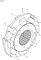
- FIG. 2 is a perspective view of the clutch ring 80.
- the clutch ring 80 includes: a ring 81 annularly extending around a center axis O; and a plurality of second dog teeth 83 protruding from end surfaces 82 in the axial direction of the ring 81 toward both sides in the axial direction.
- the center axis O of the clutch ring 80 disposed on the driving shaft 2 or the driven shaft 3 is aligned with the center axis of the driving shaft 2 or the driven shaft 3.
- the second dog teeth 83 include third teeth 84, and fourth teeth 85 having a length in the axial direction shorter than that of the third teeth 84.
- Each of the second dog teeth 83 includes: a third surface 86 facing one side in the circumferential direction; and a fourth surface 87 that is opposite to the third surface 86 and faces the other side in the circumferential direction.
- the ring 81 is divided into four parts in the circumferential direction.
- the second dog teeth 83 are joined to the ring 81 through welding or the like.
- the ring 81 connects the second dog teeth 83 at intervals in the circumferential direction.
- the third teeth 84 and the fourth teeth 85, of the second dog teeth 83, are alternately disposed in the circumferential direction.
- Each third surface 86 is an inclined surface with respect to an imaginary plane 73 parallel to the center axis O (see FIG. 3 ).
- Each fourth surface 87 is a surface parallel to the center axis O.
- teeth 88 parallel to the center axis O are formed at an inner peripheral surface of the clutch ring 80.
- teeth 88 parallel to the center axis O are formed.
- the teeth 88 are formed only at the inner sides of the third teeth 84.
- the teeth 88 extend over the whole length of each third tooth 84.
- teeth 88 parallel to the center axis O are formed.
- the teeth 88 are contiguous, without breaks, over the ring 81 and the third teeth 84 protruding from the end surfaces 82 of the ring 81. This makes the teeth 88 highly resistant to breaking.
- the teeth 88 are formed only on the second dog teeth 83.
- the case where "the teeth 88 are formed only on the second dog teeth 83" includes a case where teeth contiguous to the teeth 88 of the second dog teeth 83 are formed at the inner surface of the ring 81 as well as on the second dog teeth 83.
- the above case does not include a case where teeth not contiguous to the teeth 88 of the second dog teeth 83 are formed at the inner surface of the ring 81.
- FIG. 3 is a perspective view of the hub 70 on which the clutch ring 80 is disposed.
- splines 71 to be connected to the driving shaft 2 or the driven shaft 3 are formed.
- Grooves 72 parallel to the center axis O are formed at portions, of the outer peripheral surface of the hub 70, where the teeth 88 of the clutch ring 80 are disposed.
- the grooves 72 are formed over the whole length in the axial direction of the hub 70. Since the teeth 88 formed on the clutch ring 80 are fitted in the grooves 72 of the hub 70, the clutch ring 80 is movable in the axial direction with respect to the hub 70, but is not rotatable around the hub 70.
- the clutch ring 80 moves in the axial direction while transmitting the torque, with the teeth 88 being fitted in the grooves 72 of the hub 70.
- force is applied to the teeth 88 parallel to the center axis O. Therefore, even when there are gaps in the radial direction between the teeth 88 and the grooves 72, portions, of the teeth 88, extending in the axial direction come into contact with portions, of the grooves 72, extending in the axial direction, whereby a moment of the clutch ring 80 is reduced, and inclination of the clutch ring 80 with respect to the center axis O of the hub 70 can be reduced.
- the grooves 72 are formed at (four) portions of the hub 70, the amount of processing of the grooves 72 can be reduced as compared to the case where the grooves 72 are formed over the entire circumference of the hub 70.
- the present invention is not necessarily limited thereto.
- the grooves 72 can be formed over the entire circumference of the hub 70.
- the shapes of the grooves 72 and the teeth 88 are not particularly limited.
- the shapes of the grooves 72 and the teeth 88 may be set as appropriate.
- the grooves 72 and the teeth 88 each may have a rectangular shape or a shape surrounded by a curve such as an involute curve, when viewed from the side.
- the teeth 88 may be provided with balls or rollers that roll in the grooves 72, or the grooves 72 may be provided with balls or rollers that cause the teeth 88 to roll.
- friction between the teeth 88 and the grooves 72 can be further reduced.
- each second dog tooth 83 is inclined so as to approach the fourth surface 87 with an increase in the distance from the ring 81 in the axial direction.
- An inclination angle of the third surface 86 with respect to the imaginary plane 73 parallel to the center axis O is ⁇ .
- a radius Rd of a circle passing the center of gravity of the third surface 86 (a distance between the center axis O and the center of gravity of the third surface 86) is larger than a radius Rh of a reference circle defined by the grooves 72 (a distance between the center axis O and the reference circle defined by the grooves 72) by a thickness in the radial direction of the second dog tooth 83.
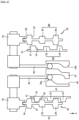
- FIG. 4 is a schematic diagram showing the transmission 1 during coast traveling at the low speed stage (fourth speed gear 40).
- FIG. 5 is a schematic diagram showing the transmission 1 during drive traveling at the low speed stage (fourth speed gear 40).
- the rotation direction of the driving gears 41, 51, the hubs 70, and the clutch rings 80 is a downward direction (direction of an arrow R) along the drawing sheet.
- the driving gear 41 has, at an end surface thereof in the axial direction, the first dog teeth 43 that mesh with the second dog teeth 83 of the clutch ring 80.
- the first dog teeth 43 include first teeth 44, and second teeth 45 having a length shorter in the axial direction than that of the first teeth 44.
- Each of the first dog teeth 43 has: a first surface 46 facing one side in the circumferential direction; and a second surface 47 that is opposite to the first surface 46 and faces the other side in the circumferential direction.
- the first surface 46 opposes the third surface 86 of the clutch ring 80.
- the second surface 47 opposes the fourth surface 87 of the clutch ring 80.
- the first surface 46 and the third surface 86 are inclined surfaces that generate a thrust that separates the driving gear 41 and the clutch ring 80 from each other in the axial direction, according to a torque in a direction in which the first surface 46 and the third surface 86 are brought into contact with each other.
- the first surface 46 is inclined so as to approach the second surface 47 with an increase in the distance from the driving gear 41.
- An inclination angle ⁇ of the first surface 46 with respect to the imaginary plane 73 (see FIG. 3 ) parallel to the center axis O is the same as the inclination angle ⁇ of the third surface 86.
- the second surface 47 and the fourth surface 87 When the second surface 47 and the fourth surface 87 are brought into contact with each other to transmit a torque, the second surface 47 and the fourth surface 87 do not cause the driving gear 41 and the clutch ring 80 to be separated from each other in the axial direction.
- the second surface 47 is a surface parallel to the center axis O.
- the driving gear 51 has, at an end surface thereof in the axial direction, first dog teeth 53 that mesh with the second dog teeth 83 of the clutch ring 80.
- the first dog teeth 53 include first teeth 54, and second teeth 55 having a length shorter in the axial direction than that of the first teeth 54.
- Each of the first dog teeth 53 has: a first surface 56 facing one side in the circumferential direction; and a second surface 57 that is opposite to the first surface 56 and faces the other side in the circumferential direction.
- the first surface 56 opposes a third surface 86 of the clutch ring 80.
- the second surface 57 opposes a fourth surface 87 of the clutch ring 80.
- the first surface 56 and the third surface 86 are inclined surfaces that generate a thrust that separates the driving gear 51 and the clutch ring 80 from each other in the axial direction, according to a torque in a direction in which the first surface 56 and the third surface 86 are brought into contact with each other.
- the first surface 56 is inclined so as to approach the second surface 57 with an increase in the distance from the driving gear 51.
- An inclination angle ⁇ of the first surface 56 with respect to the imaginary plane 73 (see FIG. 3 ) parallel to the center axis O is the same as the inclination angle ⁇ of the third surface 86.
- the second surface 57 and the fourth surface 87 When the second surface 57 and the fourth surface 87 are brought into contact with each other to transmit a torque, the second surface 57 and the fourth surface 87 do not cause the driving gear 51 and the clutch ring 80 to be separated from each other in the axial direction.
- the second surface 57 is a surface parallel to the center axis O.
- the shift fork 92 is brought close to the driving gear 41 of the fourth speed gear 40 by the shift arm 95 and the cam groove 99 of the shift drum 97, and the second dog teeth 83 of the clutch ring 80 mesh with the first dog teeth 43 of the driving gear 41.
- the teeth 88 of the clutch ring 80 are fitted in the grooves 72 of the hub 70, and the clutch ring 80 moves in the axial direction. Since the teeth 88 are formed at the inner sides of the second dog teeth 83 (third teeth 84), the length of the teeth 88 in the axial direction can be ensured as compared to the case where the teeth 88 are formed only at the inner side of the ring 81.
- the clutch ring 80 when the clutch ring 80 moves in the axial direction, the clutch ring 80 can be made harder to incline with respect to the hub 70. Meanwhile, in the fifth speed gear 50, the second dog teeth 83 of the clutch ring 80 and the first dog teeth 53 of the driving gear 51 are separated from each other in the axial direction by the shift drum 97.
- the first surfaces 46 and the third surfaces 86 generate a thrust that separates the driving gear 41 and the clutch ring 80 from each other in the axial direction, according to a torque during coasting.
- a top portion 99a (regulation portion) of the cam groove 99 of the shift drum 97 restricts movements in the axial direction of the shift arm 95 and the shift fork 92, meshing of the second dog teeth 83 of the clutch ring 80 with the first dog teeth 43 of the driving gear 41 is maintained, thereby maintaining the state where the third surfaces 86 of the clutch ring 80 are in contact with the first surfaces 46 of the driving gear 41.
- gear slip-off can be prevented by: restriction of movements in the axial direction of the shift arm 95 and the shift fork 92 by using the top portion 99a of the cam groove 99 of the shift drum 97; and friction between the second surfaces 47 and the fourth surfaces 87, or the like, thereby transmitting the driving torque.
- FIG. 6 is a schematic diagram showing the transmission 1 during shift-up from the low speed stage (fourth speed gear 40) to the high speed stage (fifth speed gear 50).
- FIG. 7 is a schematic diagram of the transmission 1 during drive traveling at the high speed stage (fifth speed gear 50).
- An arrow S shown in FIG. 6 and FIG. 7 indicates a rotation direction of the shift drum 97 during the shift-up.
- the third teeth 84 of the clutch ring 80 have a length longer in the axial direction than that of the fourth teeth 85, the third teeth 84 of the second dog teeth 83 can be easily meshed with the first dog teeth 53 (first teeth 54) of the driving gear 51.
- the shift fork 93 is brought closer to the driving gear 51 by the shift arm 96 and the cam groove 100 of the shift drum 97, and the second dog teeth 83 of the clutch ring 80 deeply mesh with the first dog teeth 53 of the driving gear 51.
- the inclination angle ⁇ of the first surfaces 46 and the third surfaces 86 causes a thrust that separates the driving gear 41 and the clutch ring 80 from each other in the axial direction, according to a torque.
- the teeth 88 formed at the inner peripheral surface of the clutch ring 80 are fitted in the grooves 72 formed at the outer peripheral surface of the hub 70, and the thrust causes the clutch ring 80 to move, while transmitting the torque, in the axial direction by an amount corresponding to the gap G of the cam groove 99.
- the hub 70 and the clutch ring 80 are set so as to satisfy tan( ⁇ - ⁇ d)/Rd- ⁇ h/Rh>0.
- gear slip-off can be prevented by: restriction of movements in the axial direction of the shift arm 96 and the shift fork 93 by using the top portion 100a of the cam groove 100 of the shift drum 97; and friction between the second surfaces 57 and the fourth surfaces 87, or the like, thereby transmitting the driving torque.
- the first surfaces 56 and the third surfaces 86 generate a thrust that separates the driving gear 51 and the clutch ring 80 from each other in the axial direction, according to the torque during coasting.
- the top portion 100a (regulation portion) of the cam groove 100 of the shift drum 97 restricts movements in the axial direction of the shift arm 96 and the shift fork 93, meshing of the second dog teeth 83 of the clutch ring 80 with the first dog teeth 53 of the driving gear 51 is maintained, thereby maintaining the state where the third surfaces 86 of the clutch ring 80 are in contact with the first surfaces 56 of the driving gear 51.
- the clutch ring 80 connected to the low-speed-stage shift gear (fourth speed gear 40) the number of rotations of which is smaller than that of the high-speed-stage shift gear (fifth speed gear 50) is pushed out in the axial direction by the thrust generated between the first surfaces 46 and the third surfaces 86, according to the internal circulation torque.
- the present invention which is defined by the appended claims, has been described with reference to the embodiment, the present invention is not limited to the above embodiment at all.
- the number of gear shift stages of the transmission 1 the shapes of the cam grooves 99, 100 formed on the shift drum 97, the number and the shape of the grooves 72 formed on the hub 70, the number and the shape of the teeth 88 formed on the clutch ring 80, and the like can be set as appropriate.
- first teeth 44, 54 and the second teeth 45, 55 of the first dog teeth 43, 53 are alternately disposed.
- the present invention is not necessarily limited thereto.
- the positions where the first teeth 44, 54 and the second teeth 45, 55 are disposed and the numbers of the respective teeth can be set as appropriate.
- the third teeth 84 and the fourth teeth 85 of the second dog teeth 83 are alternately disposed.
- the present invention is not necessarily limited thereto.
- the positions where the third teeth 84 and the fourth teeth 85 are disposed and the numbers of the respective teeth can be set as appropriate.
- the transmission 1 is mounted on an automobile.
- the transmission 1 can be mounted not only on an automobile but also on construction machinery, an industrial vehicle, agriculture machinery, and the like.
- the transmission 1 can solve torque interruption at the time of gear shift. As a result, idling of the driving shaft 2 is avoided, and fuel consumption can be improved.
- the teeth 88 formed on the second dog teeth 83 of the clutch ring 80 are contiguous to the teeth formed at a portion, of the ring 81, sandwiched by the second dog teeth 83.
- the present invention is not necessarily limited thereto.
- the teeth, of the teeth 88, formed at the portion of the ring 81 contiguous to the second dog teeth 83 can be omitted. The reason is as follows. Even when the teeth on the ring 81 are omitted, since the teeth 88 are formed on the second dog teeth 83 to which force is applied at the time of meshing, bending stress of the second dog teeth 83 can be reduced.
- the teeth 88 are formed only at the inner sides of the third teeth 84 of the second dog teeth 83.
- the present invention is not necessarily limited thereto.
- the teeth 88 can be formed not only at the inner sides of the third teeth 84 but also at the inner sides of the fourth teeth 85 and the ring 81.
- the teeth 88 can be formed on both the third teeth 84 and the fourth teeth 85.
- the second surfaces 47, 57 of the first dog teeth 43, 53 included in the driving gears 41, 51 and the fourth surfaces 87 of the second dog teeth 83 are parallel to the center axis O.
- the present invention is not necessarily limited thereto.
- a torque is transmitted with the second surfaces 47, 57 being in contact with the fourth surfaces 87, a resultant force of a component in the axial direction of force due to the torque and a component in the axial direction of friction generated between the second surfaces 47, 57 and the fourth surfaces 87 should not act in the direction in which the clutch ring 80 is separated from the driving gears 41, 51.
- the second surfaces 47, 57 and the fourth surfaces 87 may be inclined with respect to the imaginary plane 73 parallel to the center axis O.
Landscapes
- Engineering & Computer Science (AREA)
- General Engineering & Computer Science (AREA)
- Mechanical Engineering (AREA)
- Mechanical Operated Clutches (AREA)
- Gear-Shifting Mechanisms (AREA)
- Structure Of Transmissions (AREA)
Claims (3)
- Ein Getriebe mit einer formschlüssigen Kupplung (5), die dazu konfiguriert ist, ein Zahnrad (41, 51) mit einer Welle (2) selektiv zu verbinden, wobei das Zahnrad (41, 51) erste Klauenzähne (43, 53) aufweist, die an einer Endfläche davon in einer axialen Richtung ausgebildet sind, und wobei das Zahnrad (41, 53) um die Welle (2) herum angeordnet ist, wobei
die formschlüssige Kupplung (5) umfasst:eine ringförmige Nabe (70), die mit der Welle (2) verbunden ist und an ihrer äußeren Umfangsfläche Nuten (72) aufweist, die parallel zu der Welle (2) ausgebildet sind;einen ringförmigen Kupplungsring (80), der an seiner inneren Umfangsfläche parallel zur Welle (2) ausgebildete Zähne (88) und an seiner Endfläche (82) zweite Klauenzähne (83) aufweist, die mit den ersten Klauenzähnen (43) kämmen, wenn die Zähne (88) in die Nuten (72) eingesetzt sind und sich der Kupplungsring (80) dadurch in axialer Richtung bewegt; undeine Schaltvorrichtung (90), die dazu konfiguriert ist, eine Position in der axialen Richtung des Kupplungsrings (80) einzustellen, wobeijeder der ersten Klauenzähne (43, 53) eine erste Oberfläche (46, 56) aufweist, die einer Seite in einer Umfangsrichtung zugewandt ist, und eine zweite Oberfläche (47, 57), die der anderen Seite in der Umfangsrichtung zugewandt ist,jeder der zweiten Klauenzähne (83) eine dritte Oberfläche (86) aufweist, die der ersten Oberfläche (46, 56) gegenüberliegt, und eine vierte Oberfläche (87), die der zweiten Oberfläche (47, 57) gegenüberliegt,die erste Oberfläche (46) und die dritte Oberfläche (86) geneigte Oberflächen sind, die so konfiguriert sind, dass sie einen Schub erzeugen, der das Zahnrad (41, 51) und den Kupplungsring (80) in der axialen Richtung gemäß einem Drehmoment in einer Richtung voneinander trennt, in der die erste Oberfläche (46, 56) und die dritte Oberfläche (86) in Kontakt miteinander gebracht werden,die zweite Oberfläche (47, 57) und die vierte Oberfläche (87) so konfiguriert sind, dass sie nicht dazu führen, dass das Zahnrad (41, 51) und der Kupplungsring (80) in der axialen Richtung voneinander getrennt werden, wenn die zweite Oberfläche (47, 57) und die vierte Oberfläche (87) miteinander in Kontakt gebracht werden, um ein Drehmoment zu übertragen, undwenn ein Gangwechsel durchgeführt wird, die Schaltvorrichtung (90) dazu konfiguriert ist, die erste Oberfläche (46) eines der Zahnräder (41) in Kontakt mit der dritten Oberfläche (86) des Kupplungsrings (80) zu bringen, und die zweite Oberfläche (57) eines anderen der Zahnräder (51) in Kontakt mit der vierten Oberfläche (87) des Kupplungsrings (80) zu bringen, dadurch gekennzeichnet, dassder Kupplungsring (80) einen ringförmigen Ring (81) beinhaltet und die zweiten Klauenzähne (83) in der axialen Richtung von einer Stirnfläche (82) des Rings (81) vorstehen, unddie Zähne (88) an Innenseiten der zweiten Klauenzähne (83) ausgebildet sind, und wobeidie zweiten Klauenzähne (83) dritte Zähne (84) und vierte Zähne (85), die eine Länge aufweisen, die in der axialen Richtung kürzer ist als eine Länge in der axialen Richtung der dritten Zähne (84), beinhalten, unddie Zähne (88) nur an den Innenseiten der dritten Zähne (84) ausgebildet sind. - Das Getriebe (1) nach Anspruch 1, wobei
unter der Annahme, dass die Neigungswinkel der ersten Oberfläche (46) und der dritten Oberfläche (86) in Bezug auf eine imaginäre Ebene (73), die parallel zur Welle (2) verläuft, θ sind, ein Radius eines Kreises, der durch die Mitte des Schwerpunkts der dritten Oberfläche (86) verläuft, Rd ist, ein Reibungskoeffizient zwischen der ersten Oberfläche (46) und der dritten Oberfläche (86) µd ist, ein Radius eines durch die Nuten (72) definierten Bezugskreises Rh ist und ein Reibungskoeffizient zwischen den Nuten (72) und den Zähnen (88) µh ist,
- Das Getriebe (1) nach Anspruch 1 oder 2, wobeidie formschlüssige Kupplung (5) einen Spalt in der Umfangsrichtung zwischen der ersten Oberfläche (46) und der dritten Oberfläche (86) aufweist, wenn die zweite Oberfläche (47) und die vierte Oberfläche (87) in Kontakt miteinander gebracht werden, um ein Drehmoment zu übertragen, und einen Spalt in der Umfangsrichtung zwischen der zweiten Oberfläche (47) und der vierten Oberfläche (87) aufweist, wenn die erste Oberfläche (46) und die dritte Oberfläche (86) in Kontakt miteinander gebracht werden, um ein Drehmoment zu übertragen, unddie Schaltvorrichtung (90) einen Regulierungsabschnitt (99a, 100a) beinhaltet, der dazu konfiguriert ist, die Bewegung des Kupplungsrings (80) in der axialen Richtung zu begrenzen, wenn die erste Oberfläche (46) und die dritte Oberfläche (86) in Kontakt miteinander gebracht werden, um ein Drehmoment zu übertragen.
Applications Claiming Priority (1)
| Application Number | Priority Date | Filing Date | Title |
|---|---|---|---|
| PCT/JP2019/039443 WO2021070213A1 (ja) | 2019-10-07 | 2019-10-07 | 変速機 |
Publications (3)
| Publication Number | Publication Date |
|---|---|
| EP4043755A1 EP4043755A1 (de) | 2022-08-17 |
| EP4043755A4 EP4043755A4 (de) | 2023-06-21 |
| EP4043755B1 true EP4043755B1 (de) | 2024-07-17 |
Family
ID=75437022
Family Applications (1)
| Application Number | Title | Priority Date | Filing Date |
|---|---|---|---|
| EP19948479.1A Active EP4043755B1 (de) | 2019-10-07 | 2019-10-07 | Getriebe |
Country Status (3)
| Country | Link |
|---|---|
| EP (1) | EP4043755B1 (de) |
| JP (1) | JP7317321B2 (de) |
| WO (1) | WO2021070213A1 (de) |
Family Cites Families (3)
| Publication number | Priority date | Publication date | Assignee | Title |
|---|---|---|---|---|
| US4096932A (en) * | 1974-02-07 | 1978-06-27 | Liberty Jr Joseph C | Drive for power transmission |
| JP6416568B2 (ja) * | 2014-09-19 | 2018-10-31 | 株式会社イケヤフォ−ミュラ | トランスミッション |
| JP6654751B2 (ja) * | 2016-09-14 | 2020-02-26 | トヨタ自動車株式会社 | 車両用変速機 |
-
2019
- 2019-10-07 WO PCT/JP2019/039443 patent/WO2021070213A1/ja not_active Ceased
- 2019-10-07 EP EP19948479.1A patent/EP4043755B1/de active Active
- 2019-10-07 JP JP2021550946A patent/JP7317321B2/ja active Active
Also Published As
| Publication number | Publication date |
|---|---|
| JP7317321B2 (ja) | 2023-07-31 |
| JPWO2021070213A1 (de) | 2021-04-15 |
| EP4043755A1 (de) | 2022-08-17 |
| WO2021070213A1 (ja) | 2021-04-15 |
| EP4043755A4 (de) | 2023-06-21 |
Similar Documents
| Publication | Publication Date | Title |
|---|---|---|
| US12049957B2 (en) | Transmission and meshing clutch | |
| US8925410B2 (en) | Synchronizer for transmission | |
| EP3325854B1 (de) | Schaltvorrichtung | |
| WO2018173488A1 (en) | Dog clutch and transmission | |
| US10557506B2 (en) | Dog clutch | |
| JP5956805B2 (ja) | 変速機 | |
| JP4875302B2 (ja) | ドグクラッチ | |
| JP2009103248A (ja) | 変速機 | |
| US7163093B2 (en) | Synchronizer for transmission | |
| EP4043755B1 (de) | Getriebe | |
| JP2020133827A (ja) | トランスミッション及び噛合いクラッチ | |
| CN101189443A (zh) | 同步器的套筒花键结构 | |
| CN107435688B (zh) | 牙嵌式离合器装置 | |
| JP4781305B2 (ja) | 常時噛合い式歯車変速機のドッグクラッチ構造 | |
| JP2004340226A (ja) | 自動変速機の回転数検出構造 | |
| JP7562040B2 (ja) | ドッグクラッチ | |
| EP4234977B1 (de) | Kraftübertragungsvorrichtung | |
| JP6808571B2 (ja) | 摩擦係合装置の環状部材抜け止め構造 | |
| JP7413937B2 (ja) | 歯車装置 | |
| EP4234983B1 (de) | Getriebe | |
| JP7472672B2 (ja) | ドグクラッチ | |
| JP7372858B2 (ja) | 多板クラッチ | |
| JP4248965B2 (ja) | マニュアルトランスミッションのリバース機構 | |
| JP2002250410A (ja) | リバース機構 | |
| JPH08145075A (ja) | 歯車変速装置 |
Legal Events
| Date | Code | Title | Description |
|---|---|---|---|
| STAA | Information on the status of an ep patent application or granted ep patent |
Free format text: STATUS: THE INTERNATIONAL PUBLICATION HAS BEEN MADE |
|
| PUAI | Public reference made under article 153(3) epc to a published international application that has entered the european phase |
Free format text: ORIGINAL CODE: 0009012 |
|
| STAA | Information on the status of an ep patent application or granted ep patent |
Free format text: STATUS: REQUEST FOR EXAMINATION WAS MADE |
|
| 17P | Request for examination filed |
Effective date: 20220323 |
|
| AK | Designated contracting states |
Kind code of ref document: A1 Designated state(s): AL AT BE BG CH CY CZ DE DK EE ES FI FR GB GR HR HU IE IS IT LI LT LU LV MC MK MT NL NO PL PT RO RS SE SI SK SM TR |
|
| DAV | Request for validation of the european patent (deleted) | ||
| DAX | Request for extension of the european patent (deleted) | ||
| A4 | Supplementary search report drawn up and despatched |
Effective date: 20230523 |
|
| RIC1 | Information provided on ipc code assigned before grant |
Ipc: F16H 63/18 20060101ALN20230516BHEP Ipc: F16H 63/30 20060101ALI20230516BHEP Ipc: F16H 3/083 20060101AFI20230516BHEP |
|
| GRAP | Despatch of communication of intention to grant a patent |
Free format text: ORIGINAL CODE: EPIDOSNIGR1 |
|
| STAA | Information on the status of an ep patent application or granted ep patent |
Free format text: STATUS: GRANT OF PATENT IS INTENDED |
|
| INTG | Intention to grant announced |
Effective date: 20240216 |
|
| RIC1 | Information provided on ipc code assigned before grant |
Ipc: F16H 63/18 20060101ALN20240202BHEP Ipc: F16H 63/30 20060101ALI20240202BHEP Ipc: F16H 3/083 20060101AFI20240202BHEP |
|
| GRAS | Grant fee paid |
Free format text: ORIGINAL CODE: EPIDOSNIGR3 |
|
| GRAA | (expected) grant |
Free format text: ORIGINAL CODE: 0009210 |
|
| STAA | Information on the status of an ep patent application or granted ep patent |
Free format text: STATUS: THE PATENT HAS BEEN GRANTED |
|
| AK | Designated contracting states |
Kind code of ref document: B1 Designated state(s): AL AT BE BG CH CY CZ DE DK EE ES FI FR GB GR HR HU IE IS IT LI LT LU LV MC MK MT NL NO PL PT RO RS SE SI SK SM TR |
|
| REG | Reference to a national code |
Ref country code: CH Ref legal event code: EP |
|
| P01 | Opt-out of the competence of the unified patent court (upc) registered |
Free format text: CASE NUMBER: APP_38663/2024 Effective date: 20240627 |
|
| REG | Reference to a national code |
Ref country code: DE Ref legal event code: R096 Ref document number: 602019055576 Country of ref document: DE |
|
| REG | Reference to a national code |
Ref country code: IE Ref legal event code: FG4D |
|
| REG | Reference to a national code |
Ref country code: LT Ref legal event code: MG9D |
|
| PG25 | Lapsed in a contracting state [announced via postgrant information from national office to epo] |
Ref country code: PT Free format text: LAPSE BECAUSE OF FAILURE TO SUBMIT A TRANSLATION OF THE DESCRIPTION OR TO PAY THE FEE WITHIN THE PRESCRIBED TIME-LIMIT Effective date: 20241118 |
|
| REG | Reference to a national code |
Ref country code: AT Ref legal event code: MK05 Ref document number: 1704417 Country of ref document: AT Kind code of ref document: T Effective date: 20240717 |
|
| PG25 | Lapsed in a contracting state [announced via postgrant information from national office to epo] |
Ref country code: NL Free format text: LAPSE BECAUSE OF FAILURE TO SUBMIT A TRANSLATION OF THE DESCRIPTION OR TO PAY THE FEE WITHIN THE PRESCRIBED TIME-LIMIT Effective date: 20240717 |
|
| PG25 | Lapsed in a contracting state [announced via postgrant information from national office to epo] |
Ref country code: PT Free format text: LAPSE BECAUSE OF FAILURE TO SUBMIT A TRANSLATION OF THE DESCRIPTION OR TO PAY THE FEE WITHIN THE PRESCRIBED TIME-LIMIT Effective date: 20241118 Ref country code: NL Free format text: LAPSE BECAUSE OF FAILURE TO SUBMIT A TRANSLATION OF THE DESCRIPTION OR TO PAY THE FEE WITHIN THE PRESCRIBED TIME-LIMIT Effective date: 20240717 |
|
| PG25 | Lapsed in a contracting state [announced via postgrant information from national office to epo] |
Ref country code: NO Free format text: LAPSE BECAUSE OF FAILURE TO SUBMIT A TRANSLATION OF THE DESCRIPTION OR TO PAY THE FEE WITHIN THE PRESCRIBED TIME-LIMIT Effective date: 20241017 |
|
| PG25 | Lapsed in a contracting state [announced via postgrant information from national office to epo] |
Ref country code: FI Free format text: LAPSE BECAUSE OF FAILURE TO SUBMIT A TRANSLATION OF THE DESCRIPTION OR TO PAY THE FEE WITHIN THE PRESCRIBED TIME-LIMIT Effective date: 20240717 Ref country code: PL Free format text: LAPSE BECAUSE OF FAILURE TO SUBMIT A TRANSLATION OF THE DESCRIPTION OR TO PAY THE FEE WITHIN THE PRESCRIBED TIME-LIMIT Effective date: 20240717 Ref country code: GR Free format text: LAPSE BECAUSE OF FAILURE TO SUBMIT A TRANSLATION OF THE DESCRIPTION OR TO PAY THE FEE WITHIN THE PRESCRIBED TIME-LIMIT Effective date: 20241018 |
|
| PG25 | Lapsed in a contracting state [announced via postgrant information from national office to epo] |
Ref country code: BG Free format text: LAPSE BECAUSE OF FAILURE TO SUBMIT A TRANSLATION OF THE DESCRIPTION OR TO PAY THE FEE WITHIN THE PRESCRIBED TIME-LIMIT Effective date: 20240717 |
|
| PG25 | Lapsed in a contracting state [announced via postgrant information from national office to epo] |
Ref country code: LV Free format text: LAPSE BECAUSE OF FAILURE TO SUBMIT A TRANSLATION OF THE DESCRIPTION OR TO PAY THE FEE WITHIN THE PRESCRIBED TIME-LIMIT Effective date: 20240717 |
|
| PG25 | Lapsed in a contracting state [announced via postgrant information from national office to epo] |
Ref country code: IS Free format text: LAPSE BECAUSE OF FAILURE TO SUBMIT A TRANSLATION OF THE DESCRIPTION OR TO PAY THE FEE WITHIN THE PRESCRIBED TIME-LIMIT Effective date: 20241117 Ref country code: AT Free format text: LAPSE BECAUSE OF FAILURE TO SUBMIT A TRANSLATION OF THE DESCRIPTION OR TO PAY THE FEE WITHIN THE PRESCRIBED TIME-LIMIT Effective date: 20240717 |
|
| PG25 | Lapsed in a contracting state [announced via postgrant information from national office to epo] |
Ref country code: HR Free format text: LAPSE BECAUSE OF FAILURE TO SUBMIT A TRANSLATION OF THE DESCRIPTION OR TO PAY THE FEE WITHIN THE PRESCRIBED TIME-LIMIT Effective date: 20240717 |
|
| PG25 | Lapsed in a contracting state [announced via postgrant information from national office to epo] |
Ref country code: RS Free format text: LAPSE BECAUSE OF FAILURE TO SUBMIT A TRANSLATION OF THE DESCRIPTION OR TO PAY THE FEE WITHIN THE PRESCRIBED TIME-LIMIT Effective date: 20241017 Ref country code: ES Free format text: LAPSE BECAUSE OF FAILURE TO SUBMIT A TRANSLATION OF THE DESCRIPTION OR TO PAY THE FEE WITHIN THE PRESCRIBED TIME-LIMIT Effective date: 20240717 |
|
| PG25 | Lapsed in a contracting state [announced via postgrant information from national office to epo] |
Ref country code: RS Free format text: LAPSE BECAUSE OF FAILURE TO SUBMIT A TRANSLATION OF THE DESCRIPTION OR TO PAY THE FEE WITHIN THE PRESCRIBED TIME-LIMIT Effective date: 20241017 Ref country code: PL Free format text: LAPSE BECAUSE OF FAILURE TO SUBMIT A TRANSLATION OF THE DESCRIPTION OR TO PAY THE FEE WITHIN THE PRESCRIBED TIME-LIMIT Effective date: 20240717 Ref country code: NO Free format text: LAPSE BECAUSE OF FAILURE TO SUBMIT A TRANSLATION OF THE DESCRIPTION OR TO PAY THE FEE WITHIN THE PRESCRIBED TIME-LIMIT Effective date: 20241017 Ref country code: LV Free format text: LAPSE BECAUSE OF FAILURE TO SUBMIT A TRANSLATION OF THE DESCRIPTION OR TO PAY THE FEE WITHIN THE PRESCRIBED TIME-LIMIT Effective date: 20240717 Ref country code: IS Free format text: LAPSE BECAUSE OF FAILURE TO SUBMIT A TRANSLATION OF THE DESCRIPTION OR TO PAY THE FEE WITHIN THE PRESCRIBED TIME-LIMIT Effective date: 20241117 Ref country code: HR Free format text: LAPSE BECAUSE OF FAILURE TO SUBMIT A TRANSLATION OF THE DESCRIPTION OR TO PAY THE FEE WITHIN THE PRESCRIBED TIME-LIMIT Effective date: 20240717 Ref country code: GR Free format text: LAPSE BECAUSE OF FAILURE TO SUBMIT A TRANSLATION OF THE DESCRIPTION OR TO PAY THE FEE WITHIN THE PRESCRIBED TIME-LIMIT Effective date: 20241018 Ref country code: FI Free format text: LAPSE BECAUSE OF FAILURE TO SUBMIT A TRANSLATION OF THE DESCRIPTION OR TO PAY THE FEE WITHIN THE PRESCRIBED TIME-LIMIT Effective date: 20240717 Ref country code: ES Free format text: LAPSE BECAUSE OF FAILURE TO SUBMIT A TRANSLATION OF THE DESCRIPTION OR TO PAY THE FEE WITHIN THE PRESCRIBED TIME-LIMIT Effective date: 20240717 Ref country code: BG Free format text: LAPSE BECAUSE OF FAILURE TO SUBMIT A TRANSLATION OF THE DESCRIPTION OR TO PAY THE FEE WITHIN THE PRESCRIBED TIME-LIMIT Effective date: 20240717 Ref country code: AT Free format text: LAPSE BECAUSE OF FAILURE TO SUBMIT A TRANSLATION OF THE DESCRIPTION OR TO PAY THE FEE WITHIN THE PRESCRIBED TIME-LIMIT Effective date: 20240717 |
|
| PG25 | Lapsed in a contracting state [announced via postgrant information from national office to epo] |
Ref country code: RO Free format text: LAPSE BECAUSE OF FAILURE TO SUBMIT A TRANSLATION OF THE DESCRIPTION OR TO PAY THE FEE WITHIN THE PRESCRIBED TIME-LIMIT Effective date: 20240717 Ref country code: SM Free format text: LAPSE BECAUSE OF FAILURE TO SUBMIT A TRANSLATION OF THE DESCRIPTION OR TO PAY THE FEE WITHIN THE PRESCRIBED TIME-LIMIT Effective date: 20240717 Ref country code: DK Free format text: LAPSE BECAUSE OF FAILURE TO SUBMIT A TRANSLATION OF THE DESCRIPTION OR TO PAY THE FEE WITHIN THE PRESCRIBED TIME-LIMIT Effective date: 20240717 |
|
| REG | Reference to a national code |
Ref country code: DE Ref legal event code: R097 Ref document number: 602019055576 Country of ref document: DE |
|
| PG25 | Lapsed in a contracting state [announced via postgrant information from national office to epo] |
Ref country code: EE Free format text: LAPSE BECAUSE OF FAILURE TO SUBMIT A TRANSLATION OF THE DESCRIPTION OR TO PAY THE FEE WITHIN THE PRESCRIBED TIME-LIMIT Effective date: 20240717 |
|
| PG25 | Lapsed in a contracting state [announced via postgrant information from national office to epo] |
Ref country code: CZ Free format text: LAPSE BECAUSE OF FAILURE TO SUBMIT A TRANSLATION OF THE DESCRIPTION OR TO PAY THE FEE WITHIN THE PRESCRIBED TIME-LIMIT Effective date: 20240717 |
|
| PG25 | Lapsed in a contracting state [announced via postgrant information from national office to epo] |
Ref country code: SK Free format text: LAPSE BECAUSE OF FAILURE TO SUBMIT A TRANSLATION OF THE DESCRIPTION OR TO PAY THE FEE WITHIN THE PRESCRIBED TIME-LIMIT Effective date: 20240717 |
|
| PLBE | No opposition filed within time limit |
Free format text: ORIGINAL CODE: 0009261 |
|
| STAA | Information on the status of an ep patent application or granted ep patent |
Free format text: STATUS: NO OPPOSITION FILED WITHIN TIME LIMIT |
|
| REG | Reference to a national code |
Ref country code: CH Ref legal event code: PL |
|
| 26N | No opposition filed |
Effective date: 20250422 |
|
| GBPC | Gb: european patent ceased through non-payment of renewal fee |
Effective date: 20241017 |
|
| PG25 | Lapsed in a contracting state [announced via postgrant information from national office to epo] |
Ref country code: MC Free format text: LAPSE BECAUSE OF FAILURE TO SUBMIT A TRANSLATION OF THE DESCRIPTION OR TO PAY THE FEE WITHIN THE PRESCRIBED TIME-LIMIT Effective date: 20240717 |
|
| PG25 | Lapsed in a contracting state [announced via postgrant information from national office to epo] |
Ref country code: GB Free format text: LAPSE BECAUSE OF NON-PAYMENT OF DUE FEES Effective date: 20241017 |
|
| PG25 | Lapsed in a contracting state [announced via postgrant information from national office to epo] |
Ref country code: LU Free format text: LAPSE BECAUSE OF NON-PAYMENT OF DUE FEES Effective date: 20241007 Ref country code: BE Free format text: LAPSE BECAUSE OF NON-PAYMENT OF DUE FEES Effective date: 20241031 |
|
| PG25 | Lapsed in a contracting state [announced via postgrant information from national office to epo] |
Ref country code: CH Free format text: LAPSE BECAUSE OF NON-PAYMENT OF DUE FEES Effective date: 20241031 |
|
| REG | Reference to a national code |
Ref country code: BE Ref legal event code: MM Effective date: 20241031 |
|
| PG25 | Lapsed in a contracting state [announced via postgrant information from national office to epo] |
Ref country code: SE Free format text: LAPSE BECAUSE OF FAILURE TO SUBMIT A TRANSLATION OF THE DESCRIPTION OR TO PAY THE FEE WITHIN THE PRESCRIBED TIME-LIMIT Effective date: 20240717 |
|
| PG25 | Lapsed in a contracting state [announced via postgrant information from national office to epo] |
Ref country code: IE Free format text: LAPSE BECAUSE OF NON-PAYMENT OF DUE FEES Effective date: 20241007 |
|
| PGFP | Annual fee paid to national office [announced via postgrant information from national office to epo] |
Ref country code: DE Payment date: 20251028 Year of fee payment: 7 |
|
| PGFP | Annual fee paid to national office [announced via postgrant information from national office to epo] |
Ref country code: FR Payment date: 20251023 Year of fee payment: 7 |
|
| PG25 | Lapsed in a contracting state [announced via postgrant information from national office to epo] |
Ref country code: IT Free format text: LAPSE BECAUSE OF FAILURE TO SUBMIT A TRANSLATION OF THE DESCRIPTION OR TO PAY THE FEE WITHIN THE PRESCRIBED TIME-LIMIT Effective date: 20240717 Ref country code: CY Free format text: LAPSE BECAUSE OF FAILURE TO SUBMIT A TRANSLATION OF THE DESCRIPTION OR TO PAY THE FEE WITHIN THE PRESCRIBED TIME-LIMIT; INVALID AB INITIO Effective date: 20191007 |
|
| PG25 | Lapsed in a contracting state [announced via postgrant information from national office to epo] |
Ref country code: HU Free format text: LAPSE BECAUSE OF FAILURE TO SUBMIT A TRANSLATION OF THE DESCRIPTION OR TO PAY THE FEE WITHIN THE PRESCRIBED TIME-LIMIT; INVALID AB INITIO Effective date: 20191007 |