EP4040767B1 - Image processing apparatus, image processing method, and program for calibrating printer with fluorescent ink - Google Patents
Image processing apparatus, image processing method, and program for calibrating printer with fluorescent ink Download PDFInfo
- Publication number
- EP4040767B1 EP4040767B1 EP22154935.5A EP22154935A EP4040767B1 EP 4040767 B1 EP4040767 B1 EP 4040767B1 EP 22154935 A EP22154935 A EP 22154935A EP 4040767 B1 EP4040767 B1 EP 4040767B1
- Authority
- EP
- European Patent Office
- Prior art keywords
- printing
- patch
- fluorescent
- ink
- printing material
- Prior art date
- Legal status (The legal status is an assumption and is not a legal conclusion. Google has not performed a legal analysis and makes no representation as to the accuracy of the status listed.)
- Active
Links
Images


Classifications
-
- H—ELECTRICITY
- H04—ELECTRIC COMMUNICATION TECHNIQUE
- H04N—PICTORIAL COMMUNICATION, e.g. TELEVISION
- H04N1/00—Scanning, transmission or reproduction of documents or the like, e.g. facsimile transmission; Details thereof
- H04N1/46—Colour picture communication systems
- H04N1/56—Processing of colour picture signals
- H04N1/60—Colour correction or control
- H04N1/603—Colour correction or control controlled by characteristics of the picture signal generator or the picture reproducer
- H04N1/6033—Colour correction or control controlled by characteristics of the picture signal generator or the picture reproducer using test pattern analysis
-
- B—PERFORMING OPERATIONS; TRANSPORTING
- B41—PRINTING; LINING MACHINES; TYPEWRITERS; STAMPS
- B41J—TYPEWRITERS; SELECTIVE PRINTING MECHANISMS, i.e. MECHANISMS PRINTING OTHERWISE THAN FROM A FORME; CORRECTION OF TYPOGRAPHICAL ERRORS
- B41J2/00—Typewriters or selective printing mechanisms characterised by the printing or marking process for which they are designed
- B41J2/005—Typewriters or selective printing mechanisms characterised by the printing or marking process for which they are designed characterised by bringing liquid or particles selectively into contact with a printing material
- B41J2/01—Ink jet
- B41J2/205—Ink jet for printing a discrete number of tones
- B41J2/2054—Ink jet for printing a discrete number of tones by the variation of dot disposition or characteristics, e.g. dot number density, dot shape
-
- B—PERFORMING OPERATIONS; TRANSPORTING
- B41—PRINTING; LINING MACHINES; TYPEWRITERS; STAMPS
- B41J—TYPEWRITERS; SELECTIVE PRINTING MECHANISMS, i.e. MECHANISMS PRINTING OTHERWISE THAN FROM A FORME; CORRECTION OF TYPOGRAPHICAL ERRORS
- B41J2/00—Typewriters or selective printing mechanisms characterised by the printing or marking process for which they are designed
- B41J2/005—Typewriters or selective printing mechanisms characterised by the printing or marking process for which they are designed characterised by bringing liquid or particles selectively into contact with a printing material
- B41J2/01—Ink jet
- B41J2/21—Ink jet for multi-colour printing
- B41J2/2107—Ink jet for multi-colour printing characterised by the ink properties
- B41J2/2114—Ejecting specialized liquids, e.g. transparent or processing liquids
-
- B—PERFORMING OPERATIONS; TRANSPORTING
- B41—PRINTING; LINING MACHINES; TYPEWRITERS; STAMPS
- B41J—TYPEWRITERS; SELECTIVE PRINTING MECHANISMS, i.e. MECHANISMS PRINTING OTHERWISE THAN FROM A FORME; CORRECTION OF TYPOGRAPHICAL ERRORS
- B41J29/00—Details of, or accessories for, typewriters or selective printing mechanisms not otherwise provided for
- B41J29/38—Drives, motors, controls or automatic cut-off devices for the entire printing mechanism
- B41J29/393—Devices for controlling or analysing the entire machine ; Controlling or analysing mechanical parameters involving printing of test patterns
-
- G—PHYSICS
- G06—COMPUTING OR CALCULATING; COUNTING
- G06K—GRAPHICAL DATA READING; PRESENTATION OF DATA; RECORD CARRIERS; HANDLING RECORD CARRIERS
- G06K15/00—Arrangements for producing a permanent visual presentation of the output data, e.g. computer output printers
- G06K15/02—Arrangements for producing a permanent visual presentation of the output data, e.g. computer output printers using printers
- G06K15/18—Conditioning data for presenting it to the physical printing elements
- G06K15/1867—Post-processing of the composed and rasterized print image
- G06K15/1872—Image enhancement
- G06K15/1878—Adjusting colours
-
- H—ELECTRICITY
- H04—ELECTRIC COMMUNICATION TECHNIQUE
- H04N—PICTORIAL COMMUNICATION, e.g. TELEVISION
- H04N1/00—Scanning, transmission or reproduction of documents or the like, e.g. facsimile transmission; Details thereof
- H04N1/00002—Diagnosis, testing or measuring; Detecting, analysing or monitoring not otherwise provided for
- H04N1/00026—Methods therefor
- H04N1/00045—Methods therefor using a reference pattern designed for the purpose, e.g. a test chart
-
- H—ELECTRICITY
- H04—ELECTRIC COMMUNICATION TECHNIQUE
- H04N—PICTORIAL COMMUNICATION, e.g. TELEVISION
- H04N1/00—Scanning, transmission or reproduction of documents or the like, e.g. facsimile transmission; Details thereof
- H04N1/00002—Diagnosis, testing or measuring; Detecting, analysing or monitoring not otherwise provided for
- H04N1/00071—Diagnosis, testing or measuring; Detecting, analysing or monitoring not otherwise provided for characterised by the action taken
- H04N1/00082—Adjusting or controlling
- H04N1/00087—Setting or calibrating
-
- H—ELECTRICITY
- H04—ELECTRIC COMMUNICATION TECHNIQUE
- H04N—PICTORIAL COMMUNICATION, e.g. TELEVISION
- H04N1/00—Scanning, transmission or reproduction of documents or the like, e.g. facsimile transmission; Details thereof
- H04N1/46—Colour picture communication systems
- H04N1/56—Processing of colour picture signals
- H04N1/60—Colour correction or control
- H04N1/603—Colour correction or control controlled by characteristics of the picture signal generator or the picture reproducer
- H04N1/6033—Colour correction or control controlled by characteristics of the picture signal generator or the picture reproducer using test pattern analysis
- H04N1/6038—Colour correction or control controlled by characteristics of the picture signal generator or the picture reproducer using test pattern analysis for controlling interaction among colorants
-
- H—ELECTRICITY
- H04—ELECTRIC COMMUNICATION TECHNIQUE
- H04N—PICTORIAL COMMUNICATION, e.g. TELEVISION
- H04N1/00—Scanning, transmission or reproduction of documents or the like, e.g. facsimile transmission; Details thereof
- H04N1/46—Colour picture communication systems
- H04N1/56—Processing of colour picture signals
- H04N1/60—Colour correction or control
- H04N1/603—Colour correction or control controlled by characteristics of the picture signal generator or the picture reproducer
- H04N1/6052—Matching two or more picture signal generators or two or more picture reproducers
- H04N1/6055—Matching two or more picture signal generators or two or more picture reproducers using test pattern analysis
-
- B—PERFORMING OPERATIONS; TRANSPORTING
- B41—PRINTING; LINING MACHINES; TYPEWRITERS; STAMPS
- B41J—TYPEWRITERS; SELECTIVE PRINTING MECHANISMS, i.e. MECHANISMS PRINTING OTHERWISE THAN FROM A FORME; CORRECTION OF TYPOGRAPHICAL ERRORS
- B41J29/00—Details of, or accessories for, typewriters or selective printing mechanisms not otherwise provided for
- B41J29/38—Drives, motors, controls or automatic cut-off devices for the entire printing mechanism
- B41J29/393—Devices for controlling or analysing the entire machine ; Controlling or analysing mechanical parameters involving printing of test patterns
- B41J2029/3935—Devices for controlling or analysing the entire machine ; Controlling or analysing mechanical parameters involving printing of test patterns by means of printed test patterns
-
- C—CHEMISTRY; METALLURGY
- C09—DYES; PAINTS; POLISHES; NATURAL RESINS; ADHESIVES; COMPOSITIONS NOT OTHERWISE PROVIDED FOR; APPLICATIONS OF MATERIALS NOT OTHERWISE PROVIDED FOR
- C09D—COATING COMPOSITIONS, e.g. PAINTS, VARNISHES OR LACQUERS; FILLING PASTES; CHEMICAL PAINT OR INK REMOVERS; INKS; CORRECTING FLUIDS; WOODSTAINS; PASTES OR SOLIDS FOR COLOURING OR PRINTING; USE OF MATERIALS THEREFOR
- C09D11/00—Inks
- C09D11/30—Inkjet printing inks
- C09D11/38—Inkjet printing inks characterised by non-macromolecular additives other than solvents, pigments or dyes
-
- G—PHYSICS
- G03—PHOTOGRAPHY; CINEMATOGRAPHY; ANALOGOUS TECHNIQUES USING WAVES OTHER THAN OPTICAL WAVES; ELECTROGRAPHY; HOLOGRAPHY
- G03G—ELECTROGRAPHY; ELECTROPHOTOGRAPHY; MAGNETOGRAPHY
- G03G15/00—Apparatus for electrographic processes using a charge pattern
- G03G15/50—Machine control of apparatus for electrographic processes using a charge pattern, e.g. regulating differents parts of the machine, multimode copiers, microprocessor control
- G03G15/5062—Machine control of apparatus for electrographic processes using a charge pattern, e.g. regulating differents parts of the machine, multimode copiers, microprocessor control by measuring the characteristics of an image on the copy material
-
- G—PHYSICS
- G06—COMPUTING OR CALCULATING; COUNTING
- G06K—GRAPHICAL DATA READING; PRESENTATION OF DATA; RECORD CARRIERS; HANDLING RECORD CARRIERS
- G06K15/00—Arrangements for producing a permanent visual presentation of the output data, e.g. computer output printers
- G06K15/02—Arrangements for producing a permanent visual presentation of the output data, e.g. computer output printers using printers
- G06K15/027—Test patterns and calibration
-
- H—ELECTRICITY
- H04—ELECTRIC COMMUNICATION TECHNIQUE
- H04N—PICTORIAL COMMUNICATION, e.g. TELEVISION
- H04N1/00—Scanning, transmission or reproduction of documents or the like, e.g. facsimile transmission; Details thereof
- H04N1/00002—Diagnosis, testing or measuring; Detecting, analysing or monitoring not otherwise provided for
-
- H—ELECTRICITY
- H04—ELECTRIC COMMUNICATION TECHNIQUE
- H04N—PICTORIAL COMMUNICATION, e.g. TELEVISION
- H04N1/00—Scanning, transmission or reproduction of documents or the like, e.g. facsimile transmission; Details thereof
- H04N1/46—Colour picture communication systems
- H04N1/54—Conversion of colour picture signals to a plurality of signals some of which represent particular mixed colours, e.g. for textile printing
-
- H—ELECTRICITY
- H04—ELECTRIC COMMUNICATION TECHNIQUE
- H04N—PICTORIAL COMMUNICATION, e.g. TELEVISION
- H04N1/00—Scanning, transmission or reproduction of documents or the like, e.g. facsimile transmission; Details thereof
- H04N1/46—Colour picture communication systems
- H04N1/56—Processing of colour picture signals
- H04N1/60—Colour correction or control
- H04N1/603—Colour correction or control controlled by characteristics of the picture signal generator or the picture reproducer
- H04N1/6033—Colour correction or control controlled by characteristics of the picture signal generator or the picture reproducer using test pattern analysis
- H04N1/6044—Colour correction or control controlled by characteristics of the picture signal generator or the picture reproducer using test pattern analysis involving a sensor integrated in the machine or otherwise specifically adapted to read the test pattern
-
- H—ELECTRICITY
- H04—ELECTRIC COMMUNICATION TECHNIQUE
- H04N—PICTORIAL COMMUNICATION, e.g. TELEVISION
- H04N1/00—Scanning, transmission or reproduction of documents or the like, e.g. facsimile transmission; Details thereof
- H04N1/46—Colour picture communication systems
- H04N1/56—Processing of colour picture signals
- H04N1/60—Colour correction or control
- H04N1/603—Colour correction or control controlled by characteristics of the picture signal generator or the picture reproducer
- H04N1/6033—Colour correction or control controlled by characteristics of the picture signal generator or the picture reproducer using test pattern analysis
- H04N1/605—Colour correction or control controlled by characteristics of the picture signal generator or the picture reproducer using test pattern analysis for controlling ink amount, strike-through, bleeding soakage or the like
Definitions
- the present disclosure relates to a technique to make uniform the printed color tone among printing apparatuses in a system having a plurality of printing apparatus.
- color calibration is known in which a printed halftone patch is read by a measuring device and the color density of a printing apparatus is made uniform among the apparatuses by changing the amount of ink to be discharged.
- Japanese Patent Laid-Open No. 2014-136413 has disclosed a method of creating a color shift correction table based on the density characteristic in conformity to visual sensation by correcting the actually measured density detected by an optical sensor in accordance with fluorescence information on ink as a technique relating to color calibration of fluorescent ink. Specifically, correction to weight the actually measured density in conformity to visual sensation.
- US 2017/247560 A1 discloses an ink image matter generating method for selecting a fluorescent ink by performing (a) a process of color-measuring a target color which is a target of color reproduction on a medium and the medium on which an inkjet color ink for color reproduction of the target color is printed; (b) a process of calculating a difference between a colorimetric value of the target color and a colorimetric value of the medium on which the color ink is printed; and (c) a process of selecting a fluorescent ink for reducing the difference between the colorimetric value of the target color and the colorimetric value of the medium on which the color ink is printed, from fluorescent inks that are set in advance, and jetting droplets of the selected fluorescent ink together with the color ink, or after the droplets of the color ink are jetted to cause the fluorescent ink to exist on a surface of an ink image matter, thereby making it possible to select and use an appropriate fluorescent ink with respect to a specific color of which the color reproduc
- JP 2019 181863 A is concerned with suitably performing prediction of a printing result when using, for example, a characteristic ink, and discloses a method for creating a numerical expression for prediction of a printing result, used for prediction of a result of printing performed by use of an ink.
- This method comprises a stage of creating a printed matter for evaluation which is used for evaluation of a printing result, and at which the printed matter for evaluation, which includes a pattern of which a printing density is differed at plural stages, is created; a measuring stage at which a bidirectional reflectance distribution function is measured in association with the printing density; and a stage of calculating a numerical expression of prediction of a printing result on the basis of a measurement result at the measuring stage, and at which the numerical expression of prediction of a printing result is created on the basis of at least the bidirectional reflectance distribution function associated with the printing density.
- JP 2014 136413 A is concerned with an inkjet recording device capable of normally being calibrated in a visible light region to realize stable color reproducibility even when using ink generating subsidiary light such as fluorescence, and discloses that a measured density detected by an optical sensor is corrected according to fluorescence information of ink, and a color shift correction table is prepared based on a density characteristic according to visual sensation. By such a calibration process, visually stable color reproduction can be realized.
- one embodiment of the present invention provides, at a low cost, highly accurate color calibration in a printing apparatus that performs printing using fluorescent ink.
- the present invention provides a printing apparatus, a printing method, and a program as specified in the appended claims.
- an ink jet printer (in the following, also referred to simply as "printer") is supposed.
- the printer internally includes LED light sources of RGB for measuring a printed patch chart and a color sensor consisting of a light-receiving element, which is a photodiode
- the printer prints any patch chart and the printed patch chart can be measured with this color sensor.
- the printer it is also possible for the printer to function simply as a printing apparatus and perform printing processing based on printing-target data, such as a document and an image having been processed by various kinds of software.
- the printer has, as color materials, six color inks of C (cyan), M (magenta), Y (yellow), K (black), FP (fluorescent pink), and G (green).
- the combination of inks is not limited to this.
- the combination with particular color inks of R (red), Or (orange), B (blue), Gy (gray) and the like may be accepted and the combination may have Lc (light cyan) obtained by diluting C (cyan) and Lm (light magenta) obtained by diluting M (magenta).
- FB fluorescent blue
- FY fluorescent yellow
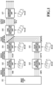
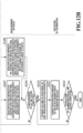
- FIG. 1 is a block diagram showing the configuration relating to color conversion processing of an image processing unit in the present embodiment. It is assumed that the printer in the present embodiment has both the function of an RGB printer to which RGB signals are input and the function of a CMYK printer to which CMYK signals are input. Further, for convenience of explanation, it is assumed that image data is processed as a signal value in which each color is represented by eight bits. However, it is needless to say that the same effect can be obtained in a case where the pixel value of each pixel of image data is represented by ten bits, 12 bits, or 16 bits.
- color separation processing unit 104 For the image data that is output from the color matching processing unit 102, by a color separation processing unit 104, color separation processing to convert color data in a device-dependent space into color material color data is performed. Similarly, for the image data that is output from the color matching processing unit 103, by a color separation processing unit 105, color separation processing to convert color data in a device-dependent space into color material color data is performed.
- tone correction processing unit 106 For the color material color data that is output from the color separation processing units 104 and 105, by a tone correction processing unit 106, tone correction processing for matching the color material color data with the output characteristic of the printer is performed.
- the color matching processing unit 102 and the color separation processing unit 104 each perform color conversion processing by using a 3D-LUT.
- the color matching processing unit 103 and the color separation processing unit 105 each perform color conversion processing by using a 4D-LUT.
- the tone correction processing unit 106 performs color conversion processing by using a 1D-LUT.
- the image processing unit has a calibration processing unit 107.
- the calibration processing unit 107 corrects the color variation of printing results, which is caused by individual differences in devices constituting the printer, printing media, color materials and the like, and the variation in volume of discharge resulting from the change over time of the devices. Specifically, the calibration processing unit 107 performs processing using a 1D-LUT for each color material color signal. The reason this processing is performed is for matching the density value in the printing unit for the input data value of an actual printing apparatus with a calibration target value, which is the density value in the printing unit for the input value of a reference apparatus.
- the configuration in which the printing apparatus has the image processing unit is described, but it may also be possible to provide the image processing unit separate from the printing apparatus and for example, it may also be possible for an information processing apparatus, such as a personal computer, to perform the function of the image processing unit.
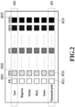
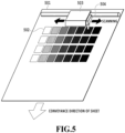
- FIG. 2 shows a patch part for measuring the density value at the time of actual printing for predetermined input data value as printing results of an actual printing apparatus, which is used at the time of execution of calibration.
- This patch chart has a plurality of patches for each ink.
- the input signal of the color material color is changed at an interval of 20% and by measuring the color of the printed patch chart, it is possible to estimate the volume of discharge corresponding to each color material in the printer.
- a patch P20 of cyan is printed only in cyan ink and a patch 201 is printed in cyan ink whose applying amount is 0%, a patch P202 is printed in cyan ink whose applying amount is 20%, and a patch P203 is printed in cyan ink whose applying amount is 120%.
- a patch of fluorescent pink is printed by the color material of fluorescent pink whose input signal is changed at an interval of 20% and the color material of green whose input signal is fixed to an input signal of a constant amount of 80%. That is, a patch P21 of fluorescent pink is printed in fluorescent pink and green inks. Specifically, a patch P211 is printed in fluorescent pink ink whose applying amount is 0% and in green ink whose applying amount is 80%, a patch P212 is printed in fluorescent pink ink whose applying amount is 20% and in green ink whose applying amount is 80%, and a patch P213 is printed in fluorescent pink ink whose applying amount is 120% and in green ink whose applying amount is 80%.
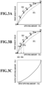
- FIG. 3A is a diagram for explaining 1D-LUT data that is used in the calibration processing unit 107 in FIG. 1 .
- FIG. 3A shows an example by one ink type of a certain medium and the vertical axis represents the print density value of the printing unit, which is read by a sensor, and the horizontal axis represents the applying amount (%) in a case where a patch is printed.
- the applying amount refers to a ratio of the number of ink dots to be printed on the paper surface.
- 100% refers to the state where one dot is printed at all the plurality of grids.
- 200% refers to the state where two dots are printed at each grid for all the grids of 1,200 dpi ⁇ 1,200 dpi (state where the number of dots double that of 100% is printed).
- the position at which a dot is printed does not necessarily need to be the center of the grid and a dot may be printed between dots.
- P (0) is the reflection coefficient of the patch in the paper white area.
- P (C) is the reflection coefficient of ink whose applying amount is C%, a predetermined constant.
- a curve indicated by a broken line 301 in FIG. 3B and the like indicates the print density value of the color material in the reference apparatus for the input data value, indicating the calibration target value.
- the reference apparatus is the printer that serves as a reference and refers to the printer whose volume of discharge is located at the center of the variation of the amounts of discharge of the actual apparatuses.
- the information relating to the calibration target value such as this is stored in advance in the storage unit of each printer within the system.
- a curve indicated by a solid line 302 indicates the print density values of the color material of the actual apparatus.
- the actual apparatus refers to the printer that performs calibration. This information is obtained by printing the patch chart in FIG. 2 and reading the printed patch chart with a sensor.
- D0 to D6 each indicate the density (calculated by formula 1) corresponding to each patch at an interval of 20% from 0% to 120% of the patch chart.
- the solid line 302 is derived by using interpolation processing, an approximate curve and the like based on the measured values of D0 to D6.
- the volume of discharge of the color material of the actual apparatus is larger than that of the reference apparatus and in particular, in the intermediate density area, printing is performed more densely than the reference apparatus.
- the correction in the calibration processing unit 107 is to convert and correct the contone color material signal for each color material color so that the print density becomes the print density of the reference apparatus and the calibration processing unit 107 performs correction processing by using the correction parameter. Calculation of this correction parameter is explained by using FIG. 3B .
- the plot point D2 in FIG. 3B indicates the density value in a case where the patch whose applying amount is 40% in the patch chart in FIG. 2 is printed by the actual apparatus. This value is higher than the target density value indicated by a plot point T2 corresponding to the same applying amount. Consequently, it is necessary to match the density value of the actual apparatus with the target density value by reducing the applying amount. Specifically, a point DY at which the density value at T2 corresponds to the applying amount of the actual apparatus is found by searching the points on the solid line 302. That is, in a case where the actual apparatus is used, on a condition that printing is performed with an applying amount 303 indicated by the point DY, the print density value becomes substantially equal to the target density value.
- the 1D-LUT is correction parameters of a mathematical formula and the like that can be defined by discrete values, such as 256 points or 1,024 points, or a curve.
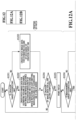
- FIG. 4 is a block diagram showing the configuration of a printing system in the present embodiment.
- the printing system has a personal computer (in the following, also referred to simply as "PC") 401 as an information processing apparatus and a printer 407 as a printing apparatus.
- the PC 401 and the printer 407 are connected via a network and an interface, such as USB and a local bus.
- the PC 401 performs processing relating to the control of the printer 407 as explained in the following in accordance with various software programs.
- a storage unit 405 system programs, application software programs, software programs necessary for the printing operation, and software programs necessary for processing, to be explained in the following, are stored. Further, in the storage unit 405, various image processing parameters, mechanism parameters, printer control data and sensor unit control data, and necessary programs, various kinds of data, and printing-target data created on the PC 401 are stored.
- the storage unit 405 is represented by a hard disk and a flash ROM.
- a CPU 403 performs predetermined processing by using a work area of a work memory 404 in accordance with various programs and various kinds of data stored in the storage unit 405.
- the printer 407 has a data transfer unit 408, a printer control unit 409, an image processing unit 410, a printing unit 411, and a sensor unit 412 and performs printing processing based on print data sent from the PC 401.
- control data of the sensor unit 412 is also included and the printer 407 performs measurement of a printed material by using the control data.
- the data transfer unit 408 extracts image data and image processing parameters from the print data sent from the PC 401 and sends them to the image processing unit 410, and extracts mechanism parameters, printer control data, and sensor unit control data and sends them to the printer control unit 409.
- the data transfer unit 408 reads information relating to results of printing, sensor measurement and the like, which is stored in the storage unit within the printer, from the storage unit and sends the read information to the PC 401.
- the printer control unit 409 includes a CPU, a ROM, a RAM and the like and controls the printing operation of the printer 407 in accordance with the printer control data sent from the data transfer unit 408. Further, the printer control unit 409 performs control of measurement by the sensor unit 412 as well as control of the printing operation.
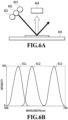
- FIG. 6A shows an outline configuration of the sensor unit.
- the sensor unit has a red LED 601, a green LED 602, a blue LED 603, and a light-receiving element 604.
- Light is emitted from the red LED 601, the green LED 602, and the blue LED 603 and light reflected from a printed material 605 is received by the light-receiving element 604.
- the color of light emitted from the LED the color of the complementary color whose density identification range is wide is selected depending on the color material that is measured. That is, measurement is performed by selecting the red LED for cyan and green, the green LED for magenta, fluorescent pink, and black, and the blue LED for yellow.
- the red LED is also called a red LED
- the green LED is also called a green LED
- the blue LED is also called a blue LED.
- the fluorescent color material is a color material that develops a color by entering the activated state by absorbing light having the activation wavelength from the ground state and returning to the ground state by emitting light having the light-emitting wavelength.
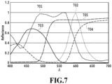
- FIG. 7 shows the intensity of activation 701 and the intensity of light emission 702 in a case where printing is performed on the sheet surface in fluorescent pink ink and the horizontal axis represents the wavelength of light and the vertical axis represents the reflectance (intensity).
- the graph shown in FIG. 7 shows the intensity of light in a case where detection is performed by changing the wavelength of light that is cast to a printed sample and the wavelength of light that is received from the sample, respectively.
- the light emission 702 indicates the intensity of light received from the printed sample for each wavelength in a case where the printed sample is irradiated with light having the wavelength causing activation.
- FIG. 7 shows the graph in a case where the printed sample is irradiated with light having a wavelength of 480 nm for the fluorescent pink in the present embodiment.
- the wavelength area in which the fluorescent ink discharged onto the sheet surface is activated is on the side of short wavelengths while overlapping the light-emitting wavelength area. Further, the activation 701 becomes strong or weak depending on the wavelength and has a wavelength at which light is emitted efficiently and a wavelength at which light is not emitted efficiently. Further, the fluorescent color material emits light, and therefore, in many cases the reflectance at the light-emitting wavelength exceeds 1.
- the color material having the characteristic as described above is defined as the fluorescent color material.
- the activation and light emission of the fluorescent pink ink are explained, but it may also be possible to adopt fluorescent ink that emits light having another wavelength in the present embodiment.
- the fluorescent ink such as this, mention is made of, for example, fluorescent blue that emits light in the blue area (from 450 nm to 500 nm) and fluorescent green that emits light in the green area (from 500 nm to 560 nm).
- fluorescent yellow that emits light in the yellow area (from 565 nm to 590 nm), fluorescent orange or fluorescent red that emits light in the red area (from 590 nm to 780 nm).
- fluorescent inks whose intensity of the wavelength causing activation is different and adjust the color tone.
- the subtractive color mixture ink is defined as ink containing a color material that absorbs light having a specific wavelength and does not emit the light among cast light.
- the subtractive color mixture ink refers to the basic color ink, such as cyan, magenta, and yellow.
- the spectral reflectance of the subtractive color mixture ink is the spectral reflectance, such as that of cyan (C) 703, magenta (M) 704, and yellow (Y) 705 in FIG. 7 . Different from the fluorescent ink, the reflectance of the subtractive color mixture ink does not exceed 1 because the subtractive color mixture ink only absorbs light.
- the fluorescent ink that is used in the present embodiment is a dispersion having the fluorescent characteristic.
- the fluorescent dispersion that is used in the present embodiment is a dispersion having the fluorescent characteristic.
- Ink is produced by combining a known solvent and a known activator with the above-described fluorescent dispersion and dispersing the fluorescent dispersion.
- the dispersion method of the fluorescent dispersion is not limited in particular.
- the surfactant it is possible to use anionic, nonionic, cationic, and bionic activators.
- the dispersion resin it is possible to use any resin having water solubility or water dispersiveness, but among others, a dispersion resin whose weight-average molecular weight is not less than 1,000 and not more than 100,000, and further, not less than 3,000 and not more than 50,000 is preferably.
- the solvent it is preferable to use, for example, a water solvent containing water or a water soluble organic solvent.
- the surface roughness of a printing medium it is sufficient to appropriately adjust the surface roughness of a printing medium in accordance with the degree of gloss required for the printing medium.
- the method of adjusting the surface roughness of a printing medium mention is made of, for example, a method in which concavities and convexities are provided by pressing the surface of the substrate or the like of a printing medium with a roll having specific concavities and convexities and the surface of the concavities and convexities is coated with an ink-receiving layer coating liquid.
- arithmetic average roughness Ra of the surface of the printing medium which is specified by JIS B 0601: 2001, is preferably 0.13 ⁇ m or less. More preferably, Ra is not less than 0.05 ⁇ m and not more than 0.13 ⁇ m and particularly preferably, Ra is not less than 0.10 ⁇ m and not more than 0.13 ⁇ m.
- the arithmetic average roughness Ra of the surface of the printing medium is preferably not less than 1.0 ⁇ m and not more than 10.0 ⁇ m and more preferably, not less than 1.0 ⁇ m and not more than 5.0 ⁇ m.
- a root-mean-square slope R ⁇ q of a roughness curve element of the surface of the printing medium, which is specified by JIS B 0601: 2001 is preferably 0.3 ⁇ m or more, and more preferably, 0.5 ⁇ m or more.
- reading of a patch by the color sensor shown in FIG. 6A is performed.
- FIG. 8A shows an ink spectral reflectance that is obtained by measuring a magenta patch printed on the paper surface by a spectral colorimeter.
- the horizontal axis represents the wavelength ⁇ and the vertical axis represents the reflectance Reflectance.
- Symbol 801 in FIG. 8A indicates the reflectance of paper white and symbols 802 to 807 each indicate the reflectance of the calibration patch in a case where the applying amount is changed at an interval of 20%.
- the color sensor of the present embodiment irradiates one of the LEDs of R, G, and B with light and receives light in the visible light area (400 to 700 nm) and in a case where the magenta patch is measured, the color sensor irradiates the green LED with light.
- the change in reflectance in a case where the amount of magenta ink is changed is large in the vicinity of 540 nm, and therefore, the use of the green LED as the LED that is irradiated with light enables efficient detection of the change in ink amount with the sensor.
- Symbol 905 in FIG. 9A shows an example of results of measuring seven patches printed in magenta ink with the color sensor.
- each LED has a bandwidth of predetermined wavelengths.
- the green LED has the light emission spectrum in the wavelength area in the vicinity of 500 to 600 nm and as shown in FIG. 6A , reflected light of irradiated light is received with the sensor.
- the output value (reflection coefficient) of the sensor is reduced. Based on this amount of reduction, the change in volume of discharge is estimated.
- the target density and the density of the actual apparatus which is calculated by formula 1 or formula 2 using the output value (reflection coefficient) of the sensor, are compared.
- the volume of discharge of the actual apparatus is smaller than the volume of discharge of the reference apparatus.
- the volume of discharge of the actual apparatus is larger than the volume of discharge of the reference apparatus.
- FIG. 9A is referred to.
- Symbol 905 in FIG. 9A indicates a relationship between the applying amount of magenta ink and the reflection coefficient calculated in accordance with formula 1.
- the difference in volume of discharge and the difference in applying amount are different, but here, the difference in volume of discharge is approximated as the difference in applying amount and in the following, the same applies.
- FIG. 8B shows an ink spectral reflectance that is obtained by measuring a patch printed on the paper surface only in fluorescent pink ink by a spectral colorimeter.
- Symbol 811 in FIG. 8B indicates the reflectance of paper white and symbols 812 to 817 each indicate the spectral reflectance of the calibration patch in a case where the applying amount is changed at an interval of 20%.
- the change in reflectance is large in the vicinity of 540 nm as in the case of magenta, and therefore, the green LED is irradiated with light.
- the slope of the relationship between the applying amount of the fluorescent pink ink and the reflection coefficient calculated in accordance with formula 1 becomes gradual compared to that of magenta (symbol 905 in FIG. 9A ).
- FIG. 8D shows an example of the spectral reflectance of the fluorescent ink halftone patch in a case where the applying amount of green ink is 80%.
- Symbol 831 in FIG. 8D indicates, as in the case of symbol 821 in FIG. 8C , the spectral reflectance of the calibration patch of green ink whose applying amount is 80%.
- symbols 832 to 837 each indicate the spectral reflectance of the calibration patch in a case where the applying amount of fluorescent pink ink is changed at an interval of 20% for green ink whose applying amount is 80%.
- the applying amount 80% of green ink is an example of a value with which the paper surface is covered with ink in view of bleed of ink discharged onto the sheet as well and this not limited depending on the sheet and ink.
- the optimum applying amount is determined by using a conditional formula to be described in ⁇ About selection of subtractive color mixture ink at the time of patch printing> to be described later.
- FIG. 10A and FIG. 10B are each a diagram for explaining measurement of a printed material by the sensor unit shown in FIG. 6A .
- FIG. 10A shows a case where printing is performed only in fluorescent pink ink
- FIG. 10B shows a case where printing is performed by mixing fluorescent pink ink with green ink, which is subtractive color mixture ink.
- fluorescent pink ink 1004 absorbs incident light and reflects light (indicated by arrow 1001) in the wavelength area, which is not absorbed, and further, emitted light (indicated by arrow 1002) of the fluorescent pink ink 1004 is added.
- at least one green ink dot covers the fluorescent pink ink dot.
- the green ink dot covers the fluorescent pink ink dot.
- FIG. 8E shows the spectral reflectance in a case where printing is performed by mixing fluorescent pink ink with yellow ink.
- Symbol 841 in FIG. 8E shows the spectral reflectance of the calibration patch of yellow ink whose applying amount is 80%.
- symbols 842 to 847 each indicate the spectral reflectance of the calibration patch in a case where the applying amount of fluorescent pink ink is changed at an interval of 20% for yellow ink whose applying amount is 80%.
- subtractive color mixture ink with which fluorescent ink is mixed in printing is characterized in that the reflectance on the side of wavelengths longer than the reference wavelength is relatively lower than the reflectance on the side of shorter wavelengths.
- ink that is mixed in printing green ink is used, but as long as this characteristic is satisfied, another ink, such as cyan ink, may be used.
- Y ⁇ fluorescence S ⁇ E ⁇ + ⁇ ⁇ ⁇ ⁇ ⁇ ⁇ activation E ⁇ activation d ⁇ activation (the origin of source is Journal of the Imaging Society of Japan, 2018, vol. 57, No. 2, pp. 207-213 )
- the intensity of light at the certain wavelength ⁇ in subtractive color mixture ink can be defined as formula 4 below because there is no light emission due to fluorescence.
- Y ⁇ subtractive S ⁇ E ⁇
- FIG. 12A and FIG. 12B Each piece of the calibration processing is performed by the CPU 403 or the like in accordance with a calibration processing program stored in the storage unit 405 (see FIG. 4 ). Parameters necessary for the calibration processing are input by a user via the UI unit 402.
- the CPU 403 creates patch image data for estimating the volume of discharge, with which subtractive color mixture ink whose reflectance of the activation wavelength of fluorescent ink is high and whose reflectance in the light-emitting wavelength area of fluorescent ink is low is mixed.
- subtractive color mixture with which fluorescent ink is mixed in printing is selected by the method described in ⁇ About selection of subtractive color mixture ink at the time of printing> described previously.
- the CPU 403 determines whether the creation of the image data of the patch chart of all the creation-target ink colors (image data of the patch chart shown in FIG. 2 ) is completed. In a case where determination results at this step are affirmative, the processing advances to S1205 after storing the created image data of the patch chart in the storage unit 405. On the other hand, in a case where the determination results at this step are negative, the processing returns to S1201.
- the printer control unit 409 reads the reflection intensity with the sensor unit 412 by casting light whose spectral distribution exists in the wavelength area including the activation wavelength of ink to the patch. Specifically, the printer control unit 409 reads the reflection intensity of the patch by the method described in ⁇ About patch printing and measurement>.
- the printer control unit 409 determines whether the measurement of the patches of all the measurement-target ink colors is completed. In a case where determination results at this step are affirmative, the processing advances to S1210 to perform calibration. On the other hand, in a case where the determination results at this step are negative, the processing returns to S1206.
- the printer control unit 409 corrects the applying amount of ink based on estimation results at S1210. Specifically, the printer control unit 409 performs correction by the method described in ⁇ About execution of calibration> described previously and performs correction processing by using the 1D-LUT stored in the calibration processing unit 107. It may also be possible to perform correction processing based on the density value calculated from the read reflection intensity and the target density value without estimating the volume of discharge from the reflection intensity read by the patch measurement (that is, without performing S1210).
- the aspect is explained in which the calibration patch chart is printed by mixing fluorescent ink and subtractive color mixture ink.
- the printing order of fluorescent ink and subtractive color mixture ink of the patch used for correction is changed in accordance with a printing medium. The reason is that there is a case where the light emission absorption efficiency of fluorescent ink is different in accordance with the printing order depending on a printing medium.
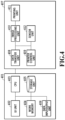
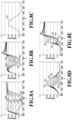
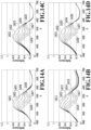
- FIG. 14A and FIG. 14B show a case where a halftone patch is printed on mat paper.
- FIG. 14A shows an example of the spectral reflectance in a case where green ink is not discharged after fluorescent pink ink at the time of printing a fluorescent pink halftone patch on mat paper by mixing fluorescent pink ink specified by the fluorescent pink halftone patch with green ink whose applying amount is 80%.
- symbol 1401 in FIG. 14A indicates the spectral reflectance of the calibration patch of the green ink whose applying amount is 80%.
- symbols 1402 to 1407 each indicate the spectral reflectance of the calibration patch in a case where the applying amount of fluorescent pink ink is changed at an interval of 20% for the green ink whose applying amount is 80%.
- FIG. 14C and FIG. 14D show a case where a halftone patch is printed on glossy paper.
- FIG. 14C shows an example of the spectral reflectance in a case where green ink is not discharged after fluorescent pink ink at the time of printing the fluorescent pink halftone patch on glossy paper by mixing fluorescent pink ink specified by the fluorescent pink halftone patch with green ink whose applying amount is 80%.
- symbol 1421 in FIG. 14C indicates the spectral reflectance of the calibration patch of green ink whose applying amount is 80%.
- symbols 1422 to 1427 each indicate the spectral reflectance of the calibration patch in a case where the applying amount of fluorescent pink ink is changed at an interval of 20% for the green ink whose applying amount is 80%.
- FIG. 14D shows an example of the spectral reflectance in a case where green ink is discharged after fluorescent pink ink at the time of printing the fluorescent pink halftone patch on glossy paper by mixing fluorescent pink ink specified by the fluorescent pink halftone patch with green ink whose applying amount is 80%.
- symbol 1431 in FIG. 14D indicates the spectral reflectance of the calibration patch of green ink whose applying amount is 80%.
- symbols 1432 to 1437 each indicate the spectral reflectance of the calibration patch in a case where the applying amount of fluorescent pink ink is changed at an interval of 20% for the green ink whose applying amount is 80%.
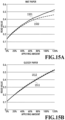
- FIG. 15A and FIG. 15B are each a diagram showing the density characteristic that is calculated by using a measured value of a halftone patch of fluorescent pink ink.
- FIG. 15A shows an example in which the density value is calculated in accordance with formula 2 by using the measured value of the patch obtained by printing the fluorescent pink halftone patch on mat paper by mixing fluorescent pink ink specified by the fluorescent pink halftone patch with green ink.
- a solid line 1501 in FIG. 15A shows the density value that is calculated based on the measured value of the patch in a case where green ink is not discharged after fluorescent pink ink.
- a broken line 1502 shows the density value that is calculated based on the measured value of the patch in a case where green ink is discharged after fluorescent pink ink.
- FIG. 15B shows an example in which the density value is calculated in accordance with formula 2 by using the measured value of the patch obtained by printing the fluorescent pink halftone patch on glossy paper by mixing fluorescent pink ink specified by the fluorescent pink halftone patch with green ink.
- a solid line 1511 in FIG. 15B shows the density value that is calculated based on the measured value of the patch in a case where green ink is not discharged after fluorescent pink ink.
- a broken line 1512 shows the density value that is calculated based on the measured value of the patch in a case where green ink is discharged after fluorescent pink ink.
- FIG.15B the density values are different. That is, in a case of glossy paper, it can be seen that the light-emitting wavelength of fluorescent pink is more absorbed in a case where green ink is discharged after fluorescent pink ink than in a case where green ink is not discharged after fluorescent pink ink.
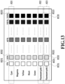
- FIG. 13 shows an example of the patch chart in the present embodiment.
- the patch of fluorescent pink is printed with the color material of fluorescent pink whose input signal is changed at an interval of 20% and the color material of green fixed to an input signal of a predetermined constant applying amount of 80%.
- a patch group P23 of Fluorescent pink 2 is a patch group for which green ink is discharged after fluorescent pink ink.
- P231 is printed with an applying amount of 0% of fluorescent pink and an applying amount of 80% of green
- P232 is printed with an applying amount of 20% of fluorescent pink and an applying amount of 80% of green
- P233 is printed with an applying amount of 120% of fluorescent pink and an applying amount of 80% of green.
- the print head in a case where printing is completed by causing the print head to perform scanning 16 times, it is possible to discharge green ink after fluorescent pink ink by discharging fluorescent pink ink at the time of the first eight-time scanning and discharging green ink at the time of the subsequent eight-time scanning. Further, by discharging both fluorescent pink and green ink at the time of the 16-time scanning, it is possible not to discharge green ink after fluorescent pink ink.
- the number of times of scanning is not limited to eight, 16 and the like and it may also be possible to perform scanning another number of times..
- FIG. 16 is a flowchart of processing to selectively adopt a measured value of a fluorescent pink patch used for generation of 1D-LUT data that is used in the calibration processing unit 107.
- Each piece of processing shown in FIG. 16 may be performed by the CPU 403 of the PC 401 or the printer control unit 409 of the printer 407.
- the patch pattern example (see FIG. 13 ) is shown in which both the patch group for which green ink is not discharged after fluorescent pink ink and the patch group for which green ink is discharged after fluorescent pink ink are printed.
- it is not necessarily required to print both the patch groups and it may also be possible to print only the patch group that is used for generation of 1D-LUT data and measure the printed patch group in accordance with the kind of printing medium on which the patch is printed.
- the kinds of printing medium are not limited to glossy paper and mat paper and another kind of printing medium may be used.
- the surface roughness of a printing medium on which printing is performed may also be possible to measure the surface roughness of a printing medium on which printing is performed and determine a patch group among a plurality of printed patch groups, from which measured values are adopted, based on the measured surface roughness, determine a patch group that is printed among a plurality of patch groups, and so on. For example, it is considered that in a case where the measured surface roughness is larger than a predetermined threshold value, the measured values of the patch group P22 of Fluorescent pink 1 are adopted and in a case where the surface roughness is less than or equal to the predetermined threshold value, the measured values of the patch group P23 of Fluorescent pink 2 are adopted.
- the kind of printing medium is not necessarily set in accordance with surface roughness.
- the kind of printing medium may be set in advance in accordance with the S/N ratio or the like of the sensor.
- the printing order of fluorescent ink and subtractive color mixture ink at the time of printing a patch used for generation of 1D-LUT data, which is used for calibration, is changed in accordance with a printing medium. Due to this, the S/N ratio of the sensor increases and it is possible to improve the correction accuracy.
- an optical filter is installed on the light-receiving side of the sensor.
- an optical filter 1102 is installed at a position at which light with which the printed surface is irradiated by an LED is received by a sensor.
- fluorescent pink ink 1101 as the candidate of the optical filter, it is possible to designate a green filter as in the case of green ink in the first embodiment.
- part of light emitted due to fluorescence is cut (indicated by arrow 1105) and a change in amount of reflected light (indicated by arrow 1103) is separated and detected. Then, it is possible to perform calibration by estimating the volume of discharge based on the detected change in amount of reflected light.
- the optical filter it is possible not only to detect the change in amount of reflected light by suppressing the amount of emitted light but also to detect the change in amount of emitted light by suppressing the change in amount of reflected light.
- FIG. 11B it is also possible to separate and detect the change in amount of emitted light (indicated by arrow 1102) by cutting (indicated by arrow 1106) part of reflected light (indicated by arrow 1103) in the activation wavelength area by using a red filter as the optical filter 1102. Then, it is possible to perform calibration by estimating the volume of discharge based on the detected change in amount of emitted light.
- the printing method of the printing apparatus the ink jet method is adopted, but the printing method of the printing apparatus is not limited to the ink jet method and other printing methods, such as the electrophotographic method and the thermal transfer method, may be adopted.
- the refection coefficient is used, but it may also be possible to use the density or the color value (CIE L*a*b*, tri-stimulus values XYZ and the like ) calculated based on the reflection coefficient.
- the configuration in which the color sensor is mounted on the side surface of the carriage is explained (see FIG. 5 ).
- the configuration may be one in which the color sensor is mounted at a position other than the side surface of the carriage or one in which it is possible to measure the patch manually.
- the configuration in which the color sensor has the LEDs of RGB is explained (see FIG. 6A and FIG. 6B ),
- the LEDs of the color sensor may be LEDs other than RGB and it may also be possible for the color sensor to have LEDs of three or more colors of LEDs of three or less colors.
- the computer may comprise one or more processors (e.g., central processing unit (CPU), micro processing unit (MPU)) and may include a network of separate computers or separate processors to read out and execute the computer executable instructions.
- the computer executable instructions may be provided to the computer, for example, from a network or the storage medium.
- the storage medium may include, for example, one or more of a hard disk, a random-access memory (RAM), a read only memory (ROM), a storage of distributed computing systems, an optical disk (such as a compact disc (CD), digital versatile disc (DVD), or Blu-ray Disc (BD) TM ), a flash memory device, a memory card, and the like. It may also be possible to appropriately combine the contents of the embodiments described previously.
Landscapes
- Engineering & Computer Science (AREA)
- Multimedia (AREA)
- Signal Processing (AREA)
- Theoretical Computer Science (AREA)
- Physics & Mathematics (AREA)
- General Physics & Mathematics (AREA)
- General Engineering & Computer Science (AREA)
- Health & Medical Sciences (AREA)
- Biomedical Technology (AREA)
- General Health & Medical Sciences (AREA)
- Ink Jet (AREA)
- Color Image Communication Systems (AREA)
- Facsimile Image Signal Circuits (AREA)
Applications Claiming Priority (1)
| Application Number | Priority Date | Filing Date | Title |
|---|---|---|---|
| JP2021019362A JP7585074B2 (ja) | 2021-02-09 | 2021-02-09 | 画像処理装置、印刷装置、画像処理方法、及びプログラム |
Publications (2)
| Publication Number | Publication Date |
|---|---|
| EP4040767A1 EP4040767A1 (en) | 2022-08-10 |
| EP4040767B1 true EP4040767B1 (en) | 2025-06-25 |
Family
ID=80225846
Family Applications (1)
| Application Number | Title | Priority Date | Filing Date |
|---|---|---|---|
| EP22154935.5A Active EP4040767B1 (en) | 2021-02-09 | 2022-02-03 | Image processing apparatus, image processing method, and program for calibrating printer with fluorescent ink |
Country Status (4)
| Country | Link |
|---|---|
| US (2) | US11915070B2 (enExample) |
| EP (1) | EP4040767B1 (enExample) |
| JP (1) | JP7585074B2 (enExample) |
| CN (1) | CN114905853A (enExample) |
Families Citing this family (5)
| Publication number | Priority date | Publication date | Assignee | Title |
|---|---|---|---|---|
| JP2022015548A (ja) * | 2020-07-09 | 2022-01-21 | 凸版印刷株式会社 | 熱転写受像シート |
| JP7674903B2 (ja) | 2021-05-10 | 2025-05-12 | キヤノン株式会社 | 画像処理装置、画像処理方法およびプログラム |
| KR20230055361A (ko) | 2021-10-18 | 2023-04-25 | 캐논 가부시끼가이샤 | 화상 처리 장치, 화상 처리 방법, 및 프로그램을 저장하는 저장 매체 |
| EP4340350A1 (en) | 2022-09-15 | 2024-03-20 | Canon Kabushiki Kaisha | Image processing apparatus, image processing method, and program |
| JP2024088389A (ja) | 2022-12-20 | 2024-07-02 | キヤノン株式会社 | 画像処理装置、画像処理方法およびプログラム |
Family Cites Families (22)
| Publication number | Priority date | Publication date | Assignee | Title |
|---|---|---|---|---|
| JP4122729B2 (ja) * | 2001-05-28 | 2008-07-23 | 富士ゼロックス株式会社 | 画像形成装置及び画像形成位置補正方法 |
| JP2003211709A (ja) * | 2002-01-24 | 2003-07-29 | Konica Corp | 蛍光インクを用いたプリント方法及びプリント装置 |
| JP4011963B2 (ja) | 2002-04-30 | 2007-11-21 | キヤノン株式会社 | データ処理装置およびその方法、並びに、画像処理装置 |
| JP3787534B2 (ja) | 2002-05-20 | 2006-06-21 | キヤノン株式会社 | 画像処理装置、画像処理方法及び画像処理プログラム |
| CA2524390C (en) * | 2003-04-04 | 2012-06-05 | Angstrom Technologies, Inc. | Methods and ink compositions for invisibly printed security images having multiple authentication features |
| EP1512537B1 (en) * | 2003-08-11 | 2008-09-17 | Canon Kabushiki Kaisha | Method of forming image, image forming apparatus and program for carrying out the method |
| US7229166B2 (en) * | 2003-08-11 | 2007-06-12 | Canon Kabushiki Kaisha | Image-forming method, image-forming apparatus, ink set, and ink |
| JP4823051B2 (ja) | 2006-12-21 | 2011-11-24 | キヤノン株式会社 | 結合ルックアップテーブルを生成する方法、画像処理装置、画像形成装置 |
| EP2122579B1 (en) * | 2007-01-23 | 2012-11-28 | Monte Ramstad | Wide color gamut anaglyphs |
| JP2009169941A (ja) * | 2007-12-21 | 2009-07-30 | Seiko Epson Corp | 印刷制御装置、印刷データ生成装置、印刷システムおよび印刷制御プログラム |
| JP5153607B2 (ja) | 2008-12-22 | 2013-02-27 | キヤノン株式会社 | 画像処理装置、画像処理方法、及び、画像処理プログラム |
| US8456709B2 (en) | 2009-11-17 | 2013-06-04 | Canon Kabushiki Kaisha | Image processing apparatus, image processing method, and lookup table generation method |
| JP5599239B2 (ja) * | 2010-06-28 | 2014-10-01 | 富士フイルム株式会社 | インクジェット印刷装置及びその印刷方法 |
| JP5863530B2 (ja) * | 2012-03-27 | 2016-02-16 | キヤノン株式会社 | 記録装置、測定装置および測定方法 |
| JP2014136413A (ja) | 2013-01-18 | 2014-07-28 | Canon Inc | インクジェット記録装置及びキャリブレーション方法 |
| US20140320927A1 (en) * | 2013-04-26 | 2014-10-30 | Chung-Hui Kuo | Inkjet printing with increased gamut |
| JP2014225845A (ja) | 2013-05-17 | 2014-12-04 | キヤノン株式会社 | 画像処理装置および画像処理方法 |
| DE112015005365B4 (de) | 2014-11-28 | 2023-09-28 | Fujifilm Corporation | Tintenbildmaterial-erzeugungsverfahren |
| JP2019181863A (ja) * | 2018-04-13 | 2019-10-24 | 株式会社ミマキエンジニアリング | 印刷結果予測用数式の作成方法、予測方法、及び予測システム |
| JP7150491B2 (ja) * | 2018-06-15 | 2022-10-11 | キヤノン株式会社 | 画像処理システム、画像形成装置、画像処理装置、画像形成装置の制御方法、画像処理装置の制御方法、及びプログラム |
| JP7105737B2 (ja) | 2018-06-29 | 2022-07-25 | キヤノン株式会社 | 画像処理装置、画像処理方法、及びプログラム |
| JP7433918B2 (ja) | 2020-01-09 | 2024-02-20 | キヤノン株式会社 | 画像処理装置及び画像処理方法 |
-
2021
- 2021-02-09 JP JP2021019362A patent/JP7585074B2/ja active Active
-
2022
- 2022-02-03 EP EP22154935.5A patent/EP4040767B1/en active Active
- 2022-02-04 US US17/665,215 patent/US11915070B2/en active Active
- 2022-02-09 CN CN202210121304.8A patent/CN114905853A/zh active Pending
-
2024
- 2024-01-19 US US18/418,128 patent/US12169744B2/en active Active
Also Published As
| Publication number | Publication date |
|---|---|
| US20240160874A1 (en) | 2024-05-16 |
| US12169744B2 (en) | 2024-12-17 |
| US11915070B2 (en) | 2024-02-27 |
| US20220253655A1 (en) | 2022-08-11 |
| CN114905853A (zh) | 2022-08-16 |
| EP4040767A1 (en) | 2022-08-10 |
| JP2022122194A (ja) | 2022-08-22 |
| JP7585074B2 (ja) | 2024-11-18 |
Similar Documents
| Publication | Publication Date | Title |
|---|---|---|
| EP4040767B1 (en) | Image processing apparatus, image processing method, and program for calibrating printer with fluorescent ink | |
| RU2372202C2 (ru) | Устройство струйной печати и способ выбора режима печати | |
| US7605943B2 (en) | Production of a color conversion profile utilizing comparison of spectral reflectance data and comparative colors | |
| US7965417B2 (en) | Tone correction table generation method and apparatus | |
| EP2629978B1 (en) | Image processing apparatus and image processing method | |
| US8947738B2 (en) | Image processing apparatus and method for reducing coloring between color ink and clear ink on a pixel region | |
| US20130128291A1 (en) | Image processing apparatus and image processing method | |
| US20150371124A1 (en) | Image processing apparatus and image processing program | |
| JP2002283675A (ja) | 画像形成装置における画像比率測定方法及び画像形成装置 | |
| US10735621B2 (en) | Printing apparatus and determination method | |
| US20230347673A1 (en) | Control apparatus, control method, and storage medium | |
| JP3818372B2 (ja) | 印刷装置、印刷制御プログラム、印刷制御プログラムを記録した媒体および印刷方法 | |
| US7557959B2 (en) | Image processing method, image processing apparatus, and program | |
| US7688486B2 (en) | Methods and apparatus for profiling color output devices | |
| JP2009071617A (ja) | 画像処理装置、画像処理方法およびプログラム | |
| US11843754B2 (en) | Image processing apparatus, image processing method, and storage medium | |
| JP2010036479A (ja) | 印刷装置および印刷方法 | |
| JP4924414B2 (ja) | 印刷制御装置、印刷システムおよび印刷制御プログラム | |
| JP5500969B2 (ja) | 画像処理装置およびその方法 | |
| JP2005231179A (ja) | インクジェット記録装置及び画像処理装置 | |
| JP2012009921A (ja) | 色補正方法および色補正プログラム | |
| JP2025037180A (ja) | 情報処理装置、及び情報処理方法 | |
| JP2010141832A (ja) | 印刷制御装置、印刷システムおよび印刷制御プログラム | |
| US12225172B2 (en) | Image processing apparatus, image processing method, and storage medium to reduce ink application amount | |
| JP2013135243A (ja) | 印刷制御装置、プログラム、及び印刷装置 |
Legal Events
| Date | Code | Title | Description |
|---|---|---|---|
| PUAI | Public reference made under article 153(3) epc to a published international application that has entered the european phase |
Free format text: ORIGINAL CODE: 0009012 |
|
| STAA | Information on the status of an ep patent application or granted ep patent |
Free format text: STATUS: THE APPLICATION HAS BEEN PUBLISHED |
|
| AK | Designated contracting states |
Kind code of ref document: A1 Designated state(s): AL AT BE BG CH CY CZ DE DK EE ES FI FR GB GR HR HU IE IS IT LI LT LU LV MC MK MT NL NO PL PT RO RS SE SI SK SM TR |
|
| STAA | Information on the status of an ep patent application or granted ep patent |
Free format text: STATUS: REQUEST FOR EXAMINATION WAS MADE |
|
| 17P | Request for examination filed |
Effective date: 20230210 |
|
| RBV | Designated contracting states (corrected) |
Designated state(s): AL AT BE BG CH CY CZ DE DK EE ES FI FR GB GR HR HU IE IS IT LI LT LU LV MC MK MT NL NO PL PT RO RS SE SI SK SM TR |
|
| GRAP | Despatch of communication of intention to grant a patent |
Free format text: ORIGINAL CODE: EPIDOSNIGR1 |
|
| STAA | Information on the status of an ep patent application or granted ep patent |
Free format text: STATUS: GRANT OF PATENT IS INTENDED |
|
| RIC1 | Information provided on ipc code assigned before grant |
Ipc: H04N 1/54 20060101ALN20241230BHEP Ipc: G01N 21/27 20060101ALN20241230BHEP Ipc: G06K 15/02 20060101ALN20241230BHEP Ipc: G03G 15/00 20060101ALN20241230BHEP Ipc: B41M 3/14 20060101ALN20241230BHEP Ipc: B41J 2/21 20060101ALI20241230BHEP Ipc: H04N 1/60 20060101ALI20241230BHEP Ipc: B41J 29/393 20060101ALI20241230BHEP Ipc: H04N 1/00 20060101AFI20241230BHEP |
|
| INTG | Intention to grant announced |
Effective date: 20250124 |
|
| GRAS | Grant fee paid |
Free format text: ORIGINAL CODE: EPIDOSNIGR3 |
|
| GRAA | (expected) grant |
Free format text: ORIGINAL CODE: 0009210 |
|
| STAA | Information on the status of an ep patent application or granted ep patent |
Free format text: STATUS: THE PATENT HAS BEEN GRANTED |
|
| AK | Designated contracting states |
Kind code of ref document: B1 Designated state(s): AL AT BE BG CH CY CZ DE DK EE ES FI FR GB GR HR HU IE IS IT LI LT LU LV MC MK MT NL NO PL PT RO RS SE SI SK SM TR |
|
| REG | Reference to a national code |
Ref country code: GB Ref legal event code: FG4D |
|
| REG | Reference to a national code |
Ref country code: CH Ref legal event code: EP |
|
| REG | Reference to a national code |
Ref country code: DE Ref legal event code: R096 Ref document number: 602022016266 Country of ref document: DE |
|
| REG | Reference to a national code |
Ref country code: CH Ref legal event code: EP |
|
| REG | Reference to a national code |
Ref country code: IE Ref legal event code: FG4D |
|
| PG25 | Lapsed in a contracting state [announced via postgrant information from national office to epo] |
Ref country code: FI Free format text: LAPSE BECAUSE OF FAILURE TO SUBMIT A TRANSLATION OF THE DESCRIPTION OR TO PAY THE FEE WITHIN THE PRESCRIBED TIME-LIMIT Effective date: 20250625 |
|
| REG | Reference to a national code |
Ref country code: LT Ref legal event code: MG9D |
|
| PG25 | Lapsed in a contracting state [announced via postgrant information from national office to epo] |
Ref country code: GR Free format text: LAPSE BECAUSE OF FAILURE TO SUBMIT A TRANSLATION OF THE DESCRIPTION OR TO PAY THE FEE WITHIN THE PRESCRIBED TIME-LIMIT Effective date: 20250926 Ref country code: NO Free format text: LAPSE BECAUSE OF FAILURE TO SUBMIT A TRANSLATION OF THE DESCRIPTION OR TO PAY THE FEE WITHIN THE PRESCRIBED TIME-LIMIT Effective date: 20250925 |
|
| PG25 | Lapsed in a contracting state [announced via postgrant information from national office to epo] |
Ref country code: BG Free format text: LAPSE BECAUSE OF FAILURE TO SUBMIT A TRANSLATION OF THE DESCRIPTION OR TO PAY THE FEE WITHIN THE PRESCRIBED TIME-LIMIT Effective date: 20250625 |
|
| PG25 | Lapsed in a contracting state [announced via postgrant information from national office to epo] |
Ref country code: HR Free format text: LAPSE BECAUSE OF FAILURE TO SUBMIT A TRANSLATION OF THE DESCRIPTION OR TO PAY THE FEE WITHIN THE PRESCRIBED TIME-LIMIT Effective date: 20250625 |
|
| PG25 | Lapsed in a contracting state [announced via postgrant information from national office to epo] |
Ref country code: RS Free format text: LAPSE BECAUSE OF FAILURE TO SUBMIT A TRANSLATION OF THE DESCRIPTION OR TO PAY THE FEE WITHIN THE PRESCRIBED TIME-LIMIT Effective date: 20250925 |
|
| PG25 | Lapsed in a contracting state [announced via postgrant information from national office to epo] |
Ref country code: LV Free format text: LAPSE BECAUSE OF FAILURE TO SUBMIT A TRANSLATION OF THE DESCRIPTION OR TO PAY THE FEE WITHIN THE PRESCRIBED TIME-LIMIT Effective date: 20250625 |
|
| REG | Reference to a national code |
Ref country code: NL Ref legal event code: MP Effective date: 20250625 |
|
| PG25 | Lapsed in a contracting state [announced via postgrant information from national office to epo] |
Ref country code: NL Free format text: LAPSE BECAUSE OF FAILURE TO SUBMIT A TRANSLATION OF THE DESCRIPTION OR TO PAY THE FEE WITHIN THE PRESCRIBED TIME-LIMIT Effective date: 20250625 |
|
| PG25 | Lapsed in a contracting state [announced via postgrant information from national office to epo] |
Ref country code: PT Free format text: LAPSE BECAUSE OF FAILURE TO SUBMIT A TRANSLATION OF THE DESCRIPTION OR TO PAY THE FEE WITHIN THE PRESCRIBED TIME-LIMIT Effective date: 20251027 |
|
| REG | Reference to a national code |
Ref country code: AT Ref legal event code: MK05 Ref document number: 1807848 Country of ref document: AT Kind code of ref document: T Effective date: 20250625 |