EP4036033A1 - Delaminated container - Google Patents
Delaminated container Download PDFInfo
- Publication number
- EP4036033A1 EP4036033A1 EP21172920.7A EP21172920A EP4036033A1 EP 4036033 A1 EP4036033 A1 EP 4036033A1 EP 21172920 A EP21172920 A EP 21172920A EP 4036033 A1 EP4036033 A1 EP 4036033A1
- Authority
- EP
- European Patent Office
- Prior art keywords
- tightly
- opening
- attached
- segment
- layer
- Prior art date
- Legal status (The legal status is an assumption and is not a legal conclusion. Google has not performed a legal analysis and makes no representation as to the accuracy of the status listed.)
- Pending
Links
- 230000004308 accommodation Effects 0.000 claims abstract description 11
- 238000007664 blowing Methods 0.000 description 16
- 238000004519 manufacturing process Methods 0.000 description 11
- 230000032798 delamination Effects 0.000 description 5
- 230000009286 beneficial effect Effects 0.000 description 3
- 238000000465 moulding Methods 0.000 description 3
- 238000000071 blow moulding Methods 0.000 description 2
- 238000011161 development Methods 0.000 description 1
- 230000018109 developmental process Effects 0.000 description 1
- 238000000034 method Methods 0.000 description 1
Images


Classifications
-
- B—PERFORMING OPERATIONS; TRANSPORTING
- B65—CONVEYING; PACKING; STORING; HANDLING THIN OR FILAMENTARY MATERIAL
- B65D—CONTAINERS FOR STORAGE OR TRANSPORT OF ARTICLES OR MATERIALS, e.g. BAGS, BARRELS, BOTTLES, BOXES, CANS, CARTONS, CRATES, DRUMS, JARS, TANKS, HOPPERS, FORWARDING CONTAINERS; ACCESSORIES, CLOSURES, OR FITTINGS THEREFOR; PACKAGING ELEMENTS; PACKAGES
- B65D83/00—Containers or packages with special means for dispensing contents
- B65D83/0055—Containers or packages provided with a flexible bag or a deformable membrane or diaphragm for expelling the contents
-
- B—PERFORMING OPERATIONS; TRANSPORTING
- B65—CONVEYING; PACKING; STORING; HANDLING THIN OR FILAMENTARY MATERIAL
- B65D—CONTAINERS FOR STORAGE OR TRANSPORT OF ARTICLES OR MATERIALS, e.g. BAGS, BARRELS, BOTTLES, BOXES, CANS, CARTONS, CRATES, DRUMS, JARS, TANKS, HOPPERS, FORWARDING CONTAINERS; ACCESSORIES, CLOSURES, OR FITTINGS THEREFOR; PACKAGING ELEMENTS; PACKAGES
- B65D1/00—Containers having bodies formed in one piece, e.g. by casting metallic material, by moulding plastics, by blowing vitreous material, by throwing ceramic material, by moulding pulped fibrous material, by deep-drawing operations performed on sheet material
- B65D1/02—Bottles or similar containers with necks or like restricted apertures, designed for pouring contents
- B65D1/0207—Bottles or similar containers with necks or like restricted apertures, designed for pouring contents characterised by material, e.g. composition, physical features
- B65D1/0215—Bottles or similar containers with necks or like restricted apertures, designed for pouring contents characterised by material, e.g. composition, physical features multilayered
-
- B—PERFORMING OPERATIONS; TRANSPORTING
- B65—CONVEYING; PACKING; STORING; HANDLING THIN OR FILAMENTARY MATERIAL
- B65D—CONTAINERS FOR STORAGE OR TRANSPORT OF ARTICLES OR MATERIALS, e.g. BAGS, BARRELS, BOTTLES, BOXES, CANS, CARTONS, CRATES, DRUMS, JARS, TANKS, HOPPERS, FORWARDING CONTAINERS; ACCESSORIES, CLOSURES, OR FITTINGS THEREFOR; PACKAGING ELEMENTS; PACKAGES
- B65D1/00—Containers having bodies formed in one piece, e.g. by casting metallic material, by moulding plastics, by blowing vitreous material, by throwing ceramic material, by moulding pulped fibrous material, by deep-drawing operations performed on sheet material
- B65D1/22—Boxes or like containers with side walls of substantial depth for enclosing contents
- B65D1/26—Thin-walled containers, e.g. formed by deep-drawing operations
- B65D1/28—Thin-walled containers, e.g. formed by deep-drawing operations formed of laminated material
-
- B—PERFORMING OPERATIONS; TRANSPORTING
- B29—WORKING OF PLASTICS; WORKING OF SUBSTANCES IN A PLASTIC STATE IN GENERAL
- B29C—SHAPING OR JOINING OF PLASTICS; SHAPING OF MATERIAL IN A PLASTIC STATE, NOT OTHERWISE PROVIDED FOR; AFTER-TREATMENT OF THE SHAPED PRODUCTS, e.g. REPAIRING
- B29C49/00—Blow-moulding, i.e. blowing a preform or parison to a desired shape within a mould; Apparatus therefor
- B29C49/24—Lining or labelling
-
- B—PERFORMING OPERATIONS; TRANSPORTING
- B29—WORKING OF PLASTICS; WORKING OF SUBSTANCES IN A PLASTIC STATE IN GENERAL
- B29C—SHAPING OR JOINING OF PLASTICS; SHAPING OF MATERIAL IN A PLASTIC STATE, NOT OTHERWISE PROVIDED FOR; AFTER-TREATMENT OF THE SHAPED PRODUCTS, e.g. REPAIRING
- B29C49/00—Blow-moulding, i.e. blowing a preform or parison to a desired shape within a mould; Apparatus therefor
- B29C49/42—Component parts, details or accessories; Auxiliary operations
- B29C49/58—Blowing means
-
- B—PERFORMING OPERATIONS; TRANSPORTING
- B32—LAYERED PRODUCTS
- B32B—LAYERED PRODUCTS, i.e. PRODUCTS BUILT-UP OF STRATA OF FLAT OR NON-FLAT, e.g. CELLULAR OR HONEYCOMB, FORM
- B32B1/00—Layered products having a non-planar shape
-
- B—PERFORMING OPERATIONS; TRANSPORTING
- B65—CONVEYING; PACKING; STORING; HANDLING THIN OR FILAMENTARY MATERIAL
- B65D—CONTAINERS FOR STORAGE OR TRANSPORT OF ARTICLES OR MATERIALS, e.g. BAGS, BARRELS, BOTTLES, BOXES, CANS, CARTONS, CRATES, DRUMS, JARS, TANKS, HOPPERS, FORWARDING CONTAINERS; ACCESSORIES, CLOSURES, OR FITTINGS THEREFOR; PACKAGING ELEMENTS; PACKAGES
- B65D1/00—Containers having bodies formed in one piece, e.g. by casting metallic material, by moulding plastics, by blowing vitreous material, by throwing ceramic material, by moulding pulped fibrous material, by deep-drawing operations performed on sheet material
- B65D1/02—Bottles or similar containers with necks or like restricted apertures, designed for pouring contents
- B65D1/0223—Bottles or similar containers with necks or like restricted apertures, designed for pouring contents characterised by shape
- B65D1/023—Neck construction
- B65D1/0246—Closure retaining means, e.g. beads, screw-threads
-
- B—PERFORMING OPERATIONS; TRANSPORTING
- B65—CONVEYING; PACKING; STORING; HANDLING THIN OR FILAMENTARY MATERIAL
- B65D—CONTAINERS FOR STORAGE OR TRANSPORT OF ARTICLES OR MATERIALS, e.g. BAGS, BARRELS, BOTTLES, BOXES, CANS, CARTONS, CRATES, DRUMS, JARS, TANKS, HOPPERS, FORWARDING CONTAINERS; ACCESSORIES, CLOSURES, OR FITTINGS THEREFOR; PACKAGING ELEMENTS; PACKAGES
- B65D1/00—Containers having bodies formed in one piece, e.g. by casting metallic material, by moulding plastics, by blowing vitreous material, by throwing ceramic material, by moulding pulped fibrous material, by deep-drawing operations performed on sheet material
- B65D1/32—Containers adapted to be temporarily deformed by external pressure to expel contents
- B65D1/323—Containers adapted to be temporarily deformed by external pressure to expel contents the container comprising internally a dip tube through which the contents pass
-
- B—PERFORMING OPERATIONS; TRANSPORTING
- B65—CONVEYING; PACKING; STORING; HANDLING THIN OR FILAMENTARY MATERIAL
- B65D—CONTAINERS FOR STORAGE OR TRANSPORT OF ARTICLES OR MATERIALS, e.g. BAGS, BARRELS, BOTTLES, BOXES, CANS, CARTONS, CRATES, DRUMS, JARS, TANKS, HOPPERS, FORWARDING CONTAINERS; ACCESSORIES, CLOSURES, OR FITTINGS THEREFOR; PACKAGING ELEMENTS; PACKAGES
- B65D85/00—Containers, packaging elements or packages, specially adapted for particular articles or materials
- B65D85/70—Containers, packaging elements or packages, specially adapted for particular articles or materials for materials not otherwise provided for
- B65D85/72—Containers, packaging elements or packages, specially adapted for particular articles or materials for materials not otherwise provided for for edible or potable liquids, semiliquids, or plastic or pasty materials
-
- B—PERFORMING OPERATIONS; TRANSPORTING
- B29—WORKING OF PLASTICS; WORKING OF SUBSTANCES IN A PLASTIC STATE IN GENERAL
- B29C—SHAPING OR JOINING OF PLASTICS; SHAPING OF MATERIAL IN A PLASTIC STATE, NOT OTHERWISE PROVIDED FOR; AFTER-TREATMENT OF THE SHAPED PRODUCTS, e.g. REPAIRING
- B29C49/00—Blow-moulding, i.e. blowing a preform or parison to a desired shape within a mould; Apparatus therefor
- B29C49/42—Component parts, details or accessories; Auxiliary operations
- B29C49/58—Blowing means
- B29C2049/5848—Cutting means, e.g. to cut parts of the preform or parison with the blowing means
-
- B—PERFORMING OPERATIONS; TRANSPORTING
- B29—WORKING OF PLASTICS; WORKING OF SUBSTANCES IN A PLASTIC STATE IN GENERAL
- B29C—SHAPING OR JOINING OF PLASTICS; SHAPING OF MATERIAL IN A PLASTIC STATE, NOT OTHERWISE PROVIDED FOR; AFTER-TREATMENT OF THE SHAPED PRODUCTS, e.g. REPAIRING
- B29C2949/00—Indexing scheme relating to blow-moulding
- B29C2949/30—Preforms or parisons made of several components
- B29C2949/3086—Interaction between two or more components, e.g. type of or lack of bonding
- B29C2949/3088—Bonding
-
- B—PERFORMING OPERATIONS; TRANSPORTING
- B29—WORKING OF PLASTICS; WORKING OF SUBSTANCES IN A PLASTIC STATE IN GENERAL
- B29C—SHAPING OR JOINING OF PLASTICS; SHAPING OF MATERIAL IN A PLASTIC STATE, NOT OTHERWISE PROVIDED FOR; AFTER-TREATMENT OF THE SHAPED PRODUCTS, e.g. REPAIRING
- B29C49/00—Blow-moulding, i.e. blowing a preform or parison to a desired shape within a mould; Apparatus therefor
- B29C49/22—Blow-moulding, i.e. blowing a preform or parison to a desired shape within a mould; Apparatus therefor using multilayered preforms or parisons
-
- B—PERFORMING OPERATIONS; TRANSPORTING
- B29—WORKING OF PLASTICS; WORKING OF SUBSTANCES IN A PLASTIC STATE IN GENERAL
- B29C—SHAPING OR JOINING OF PLASTICS; SHAPING OF MATERIAL IN A PLASTIC STATE, NOT OTHERWISE PROVIDED FOR; AFTER-TREATMENT OF THE SHAPED PRODUCTS, e.g. REPAIRING
- B29C49/00—Blow-moulding, i.e. blowing a preform or parison to a desired shape within a mould; Apparatus therefor
- B29C49/42—Component parts, details or accessories; Auxiliary operations
- B29C49/4252—Auxiliary operations prior to the blow-moulding operation not otherwise provided for
-
- B—PERFORMING OPERATIONS; TRANSPORTING
- B32—LAYERED PRODUCTS
- B32B—LAYERED PRODUCTS, i.e. PRODUCTS BUILT-UP OF STRATA OF FLAT OR NON-FLAT, e.g. CELLULAR OR HONEYCOMB, FORM
- B32B2439/00—Containers; Receptacles
Definitions
- the present disclosure relates to a delaminated container. More particularly, the present disclosure relates to a delaminated container having an opening portion without a tendency to be delaminated.
- the inner layer and the outer layer are required to be delaminated while unaffectedly unloading the content therein, but not required to be delaminated totally, and thereby there seems a conflict or a trade-off in the engineering design of the delaminated container.
- a delaminated container has a main body portion and an opening portion.
- the opening portion is located closer to an opening of the delaminated container than the main body portion located thereto.
- An accommodation space of the delaminated container is formed by a body inner surface of the main body portion and an opening inner surface of the opening portion.
- the delaminated container includes a first layer and a second layer.
- the first layer includes a first tightly-attached section. At the main body portion, the first layer is located closer to the body inner surface than the second layer located thereto and is exposed on the body inner surface.
- the second layer includes a second tightly-attached section.
- the first tightly-attached section and the second tightly-attached section are tightly attached to each other.
- the first tightly-attached section and the second tightly-attached section are both located at the opening portion of the delaminated container.
- the first tightly-attached section may include a sandwiched segment
- the second tightly-attached section may include an inner tightly-attached segment.
- the sandwiched segment and at least one part of the inner tightly-attached segment are tightly attached to each other.
- the inner tightly-attached segment is located closer to the opening inner surface than the sandwiched segment located thereto, and the sandwiched segment is not exposed on the opening inner surface.
- the inner tightly-attached segment may be not exposed on the opening inner surface.
- the first tightly-attached section may further include a first opening segment.
- the first opening segment is tightly attached to another part of the inner tightly-attached segment and exposed on the opening inner surface, and the first opening segment is extended along a direction from the opening towards the main body portion and connected to the sandwiched segment.
- the delaminated container has an opening normal direction, which is a normal direction of a virtual plane formed by the opening.
- a ratio of a length of the sandwiched segment to a length of the first opening segment may be between 0.3 and 1.
- the second tightly-attached section may include a second opening segment, and the second opening segment is exposed on the opening inner surface and extended along a direction from the opening towards the main body portion.
- the first tightly-attached section may include a sandwiched segment
- the second tightly-attached section may further include an inner tightly-attached segment.
- the sandwiched segment and at least one part of the inner tightly-attached segment are tightly attached to each other.
- the sandwiched segment is not exposed on the opening inner surface, and the second opening segment is connected to the inner tightly-attached segment.
- an inner diameter of the opening inner surface may become smaller along a direction from the opening towards the main body portion.
- a delaminated container has a main body portion and an opening portion.
- the opening portion is located closer to an opening of the delaminated container than the main body portion located thereto.
- An accommodation space of the delaminated container is formed by a body inner surface of the main body portion and an opening inner surface of the opening portion.
- the delaminated container includes a first layer and a second layer.
- the first layer includes a first tightly-attached section. At the main body portion, the first layer is located closer to the body inner surface than the second layer located thereto and is exposed on the body inner surface.
- the second layer includes a second tightly-attached section.
- the first tightly-attached section and the second tightly-attached section are tightly attached to each other.
- the first tightly-attached section and the second tightly-attached section are both located at the opening portion of the delaminated container and form an inwardly folded structure.
- the first tightly-attached section may include a sandwiched segment
- the second tightly-attached section may include an inner tightly-attached segment and an outer tightly-attached segment.
- An inner surface of the sandwiched segment and at least one part of the inner tightly-attached segment are tightly attached to each other.
- An outer surface of the sandwiched segment and at least one part of the outer tightly-attached segment are tightly attached to each other, and the sandwiched segment is not exposed on the opening inner surface.
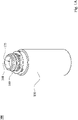
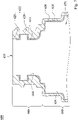
- Fig. 1A is a three-dimensional view of a delaminated container 100 according to the 1st embodiment of the present disclosure.
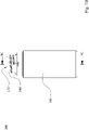
- Fig. 1B is a side view of the delaminated container 100 according to the 1st embodiment.
- Fig. 1C is a cross-sectional view along line 1C-1C of the delaminated container 100 in Fig. 1B .
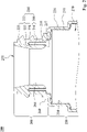
- Fig. 1D is a schematic view of part 1D in Fig. 1C .
- a delaminated container 100 has a main body portion 150 and an opening portion 160.
- the opening portion 160 is located closer to an opening 175 of the delaminated container 100 than the main body portion 150 located thereto (i.e., located to the opening 175).
- An accommodation space 170 of the delaminated container 100 is formed by a body inner surface 154 of the main body portion 150 and an opening inner surface 164 of the opening portion 160.
- the delaminated container 100 includes a first layer 110 and a second layer 120.
- the first layer 110 includes a first tightly-attached section 111.
- the first layer 110 is located closer to the body inner surface 154 than the second layer 120 located thereto (i.e., located to the body inner surface 154) and is exposed on the body inner surface 154.
- the second layer 120 includes a second tightly-attached section 122.
- the first tightly-attached section 111 and the second tightly-attached section 122 are tightly attached to each other.
- the first tightly-attached section 111 and the second tightly-attached section 122 are both located at the opening portion 160 of the delaminated container 100.
- a first layer indicates the innermost layer at a main body portion
- a second layer indicates an outer layer, i.e., except the innermost layer, at the main body portion
- a number of the second layer may be at least two.
- first tightly-attached section 111 and the second tightly-attached section 122 are both located at the opening portion 160 of the delaminated container 100 and form an inwardly folded structure 130. Accordingly, it is advantageous in preventing the delamination between the first layer 110 and the second layer 120 at the opening portion 160, reducing the manufacturing cost, and increasing the production efficiency of the delaminated container 100.
- the inwardly folded structure 130 is formed in an original and general blow molding process to enlarge a contact area of a first layer of a blank thereof (i.e., the contact area between the first layer and a second layer of the blank), so as to increase the friction to achieve the tightly-attached and covering functions.
- the delaminated container 100 can be formed integrally on the blow molding equipment without an additional tool or apparatus.
- first tightly-attached section 111 and the second tightly-attached section 122 can be formed in the manufacturing process of the delaminated container 100.
- first tightly-attached section 111 and the second tightly-attached section 122 can be formed during the blowing pin entering the molten blank prior to molding of the delaminated container 100 in the manufacturing process.
- the outer wall of the blowing pin and the first layer of the blank i.e., the inner layer or the innermost layer of the blank
- At least a part of the first layer of the blank is pulled inwardly by the outer wall of the blowing pin and folded inwardly along the opening inner surface (i.e., the inner surface at or near the opening), so that the first layer and the second layer (i.e., the outer layer of the blank) are tightly attached.
- the inwardly folded structure 130 is formed by squeezed and cutting of the outer wall of the blowing pin and the mold, so that the delaminated container 100 is featured with an enlarged contact area between the first layer 110 and the second layer 120 (i.e., the inner layer and the outer layer), and the second layer 120 has the function of covering the first layer 110 at the opening portion 160 and thereby being uneasy to peel off.
- a thickness of the first layer 110 at the opening portion 160 may be inconsistent or uneven.
- the first layer 110 is squeezed in a direction from the opening 175 toward the main body 150, and thereby the thickness of the first layer 110 becomes thicker (not shown in drawings) in the direction from the opening 175 toward the main body 150 while a shape of the opening inner surface 164 corresponding to a shape of the outer wall of the blowing pin.
- An outer shape and an appearance design of the delaminated container 100 can be unaffected due to only the opening inner surface 164 of the opening portion 160 is molded by the blowing pin.
- a blank may be squeezed and cut at an opening by an outer wall of a blowing pin and a mold with corresponding shapes, then high-pressure air is blown into the blank, and a delaminated container is formed integrally with an individual or different shape of an opening portion.
- the first tightly-attached section 111 includes a sandwiched segment 116.
- the second tightly-attached section 122 includes an inner tightly-attached segment 127.
- the sandwiched segment 116 and at least one part of the inner tightly-attached segment 127 are tightly attached to each other to increase the friction.
- the inner tightly-attached segment 127 is located closer to the opening inner surface 164 than the sandwiched segment 116 located thereto (i.e., located to the opening inner surface 164), and the sandwiched segment 116 is not exposed on the opening inner surface 164. Therefore, the sandwiched segment 116 of the first layer 110 is covered by the second layer 120 so as to increase the tightly attached strength.
- a delaminated container has an opening normal direction, which is a normal direction of a virtual plane formed by an opening thereof. A part of a second layer is existed in a vertical direction which is toward an opening inner surface of the said normal direction with respect to a sandwiched segment.
- the inner tightly-attached segment 127 is not exposed on the opening inner surface 164. Therefore, the first layer 110 exposed on the opening inner surface 164 is beneficial to simultaneously prevent from the delamination and reduce the manufacturing complexity.
- the first tightly-attached section 111 further includes a first opening segment 115.
- the first opening segment 115 is tightly attached to another part of the inner tightly-attached segment 127 and exposed on the opening inner surface 164.
- the first opening segment 115 is extended along the direction from the opening 175 towards the main body portion 150 and connected to the sandwiched segment 116. Accordingly, in the manufacturing process of the delaminated container 100, only a part of the first layer (i.e., the second layer being excluded) of the blank is pulled inwardly by the outer wall of the blowing pin and folded inwardly along the opening inner surface so as to be tightly-attached the second layer of the blank.
- the first opening segment 115 of the first layer 110 of the delaminated container 100 after molding is exposed on the opening inner surface 164 at a position corresponding to the opening 175, and it is advantageous in preventing the delamination between the first layer 110 and the second layer 120 at the opening portion 160.
- the delaminated container 100 has an opening normal direction N1, which is a normal direction of a virtual plane 176 formed by the opening 175.
- a ratio of a length L6 of the sandwiched segment 116 to a length L5 of the first opening segment 115 is between 0.3 and 1 (0.3 and 1 being included).
- the length L6 is 2.4 mm
- the length L5 is 6.9 mm
- the ratio of the length L6 to the length L5 is 0.35.
- the lengths L5 and L6 can be adjusted according to depths of the blowing pin entering the blank in the manufacturing process of the delaminated container 100. Therefore, it is beneficial to increase the tightly-attached firmness.
- An inner diameter of the opening inner surface 164 becomes smaller along a direction from the opening 175 towards the main body portion 150. Accordingly, the first tightly-attached section 111 tightly-attached the second tightly-attached section 122 in a non-parallel manner is advantageous in reducing the risk of being easily peeling off or delaminated and simultaneously maintaining the convenience of manufacturing.
- the shape of the opening inner surface 164 can be corresponding to the shape of the outer wall of the blowing pin used in the manufacturing process of the delaminated container 100, that is, a shape of at least one part of the outer wall of the blowing pin may be narrower at a position closer to a tip of the blowing pin and wider at another position farther from the tip thereof. In other embodiment according to the present disclosure, a shape of an outer wall of the blowing pin may be in other geometric shapes.
- the second tightly-attached section 122 further includes an outer tightly-attached segment 128.
- An inner surface 117 of the sandwiched segment 116 and the part of the inner tightly-attached segment 127 are tightly attached to each other, and an outer surface 118 of the sandwiched segment 116 and one part of the outer tightly-attached segment 128 are tightly attached to each other, so as to increase the friction.
- the sandwiched segment 116 is not exposed on the opening inner surface 164. Therefore, the sandwiched segment 116 of the first tightly-attached section 111 being covered inwardly and outwardly by the second layer 120 is advantageous in increasing the tightly attached strength.
- the first tightly-attached section 111 includes the first opening segment 115 and the sandwiched segment 116 in order along the direction from the opening 175 towards the main body portion 150.
- the second tightly-attached section 122 includes the inner tightly-attached segment 127 and the outer tightly-attached segment 128 in order along a direction from the opening inner surface 164, via the opening 175 towards an opening outer surface 169. That is, the inner tightly-attached segment 127 and the outer tightly-attached segment 128 of the second tightly-attached section 122 cover the sandwiched segment 116 of the first tightly-attached section 111, and are connected to each other near an end of the sandwiched segment 116 which is farther from the main body portion 150.
- the first tightly-attached section 111 and the second tightly-attached section 122 form the inwardly folded structure 130, which may be only formed by inwardly folding of the first layer of the blank of the delaminated container 100. Furthermore, the first opening segment 115 of the first tightly-attached section 111 is exposed on the opening inner surface 164, and the second tightly-attached section 122 is not exposed on the opening inner surface 164.
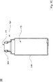
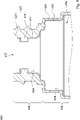
- Fig. 2 is a partially cross-sectional view of a delaminated container 200 according to the 2nd embodiment of the present disclosure.
- a delaminated container 200 has a main body portion 250 and an opening portion 260.
- the opening portion 260 is located closer to an opening 275 of the delaminated container 200 than the main body portion 250 located thereto.
- An accommodation space 270 of the delaminated container 200 is formed by a body inner surface 254 of the main body portion 250 and an opening inner surface 264 of the opening portion 260.
- the delaminated container 200 includes a first layer 210 and a second layer 220.
- the first layer 210 includes a first tightly-attached section 211.
- the first layer 210 is located closer to the body inner surface 254 than the second layer 220 located thereto and is exposed on the body inner surface 254.
- the second layer 220 includes a second tightly-attached section 222.
- the first tightly-attached section 211 and the second tightly-attached section 222 are tightly attached to each other.
- the first tightly-attached section 211 and the second tightly-attached section 222 are both located at the opening portion 260 of the delaminated container 200 and form an inwardly folded structure 230.
- the first tightly-attached section 211 includes a sandwiched segment 216.
- the second tightly-attached section 222 includes an inner tightly-attached segment 227 and an outer tightly-attached segment 228.
- An inner surface 217 of the sandwiched segment 216 and the inner tightly-attached segment 227 are tightly attached to each other.
- An outer surface 218 of the sandwiched segment 216 and the outer tightly-attached segment 228 are tightly attached to each other. There may be an air gap (reference number omitted) existed in or not in the sandwiched segment 216.
- the inner tightly-attached segment 227 is located closer to the opening inner surface 264 than the sandwiched segment 216 located thereto and is exposed on the opening inner surface 264, and the sandwiched segment 216 is not exposed on the opening inner surface 264. Furthermore, an inner diameter of the opening inner surface 264 becomes smaller along a direction from the opening 275 towards the main body portion 250.
- the second tightly-attached section 222 further includes a second opening segment 225.
- the second opening segment 225 is exposed on the opening inner surface 264 and extended along the direction from the opening 275 towards the main body portion 250. Accordingly, in the manufacturing process of the delaminated container 200, a part of a first layer and a part of a second layer of a blank of the delaminated container 200 are pulled inwardly together by an outer wall of a blowing pin and folded inwardly along an opening inner surface (i.e., an inner surface at or near an opening of the blank), so that the first layer and the second layer of the blank (i.e., an inner layer and an outer layer of the blank) are tightly attached to enlarge the contact area and the friction therebetween.
- the second layer 220 of the delaminated container 200 after molding is exposed on the opening inner surface 264 at a position of the opening 275, and the first layer 210 and the second layer 220 are uneasy to peel off at the opening portion 260.
- the sandwiched segment 216 and the inner tightly-attached segment 227 are tightly attached to each other, and the sandwiched segment 216 is not exposed on the opening inner surface 264.
- the second opening segment 225 is connected to the inner tightly-attached segment 227. Therefore, it is beneficial to implement the inwardly folded structure 230, which is formed by the first layer and the second layer folded inwardly together of the blank of the delaminated container 200.
- the second tightly-attached section 222 includes the inner tightly-attached segment 227, the second opening segment 225 and the outer tightly-attached segment 228 in order along a direction from the opening inner surface 264, via the opening 275 towards an opening outer surface 269. That is, the inner tightly-attached segment 227, the second opening segment 225 and the outer tightly-attached segment 228 of the second tightly-attached section 222 cover inwardly and outwardly the sandwiched segment 216 of the first tightly-attached section 211, and are connected near an end of the sandwiched segment 216 which is farther from the main body portion 250.
- the first tightly-attached section 211 and the second tightly-attached section 222 form the inwardly folded structure 230, which may be formed by inwardly folding together of the first layer and the second layer of the blank of the delaminated container 200. Furthermore, the second opening segment 225, the inner tightly-attached segment 227 of the second tightly-attached section 222 and the first tightly-attached section 211 are exposed on the opening inner surface 264 in order along the direction from the opening 275 towards the main body portion 250.
- Fig. 3 is a partially cross-sectional view of a delaminated container 300 according to the 3rd embodiment of the present disclosure.
- a delaminated container 300 has a main body portion 350 and an opening portion 360.
- the opening portion 360 is located closer to an opening 375 of the delaminated container 300 than the main body portion 350 located thereto.
- An accommodation space 370 of the delaminated container 300 is formed by a body inner surface 354 of the main body portion 350 and an opening inner surface 364 of the opening portion 360.
- the delaminated container 300 includes a first layer 310 and a second layer 320.
- the first layer 310 includes a first tightly-attached section 311.
- the first layer 310 is located closer to the body inner surface 354 than the second layer 320 located thereto and is exposed on the body inner surface 354.
- the second layer 320 includes a second tightly-attached section 322.
- the first tightly-attached section 311 and the second tightly-attached section 322 are tightly attached to each other.
- the first tightly-attached section 311 and the second tightly-attached section 322 are both located at the opening portion 360 of the delaminated container 300 and form an inwardly folded structure 330.
- the first tightly-attached section 311 includes a sandwiched segment 316.
- the second tightly-attached section 322 includes an inner tightly-attached segment 327 and an outer tightly-attached segment 328.
- An inner surface 317 of the sandwiched segment 316 and the inner tightly-attached segment 327 are tightly attached to each other.
- An outer surface 318 of the sandwiched segment 316 and the outer tightly-attached segment 328 are tightly attached to each other.
- the inner tightly-attached segment 327 is located closer to the opening inner surface 364 than the sandwiched segment 316 located thereto and is exposed on the opening inner surface 364, and the sandwiched segment 316 is not exposed on the opening inner surface 364. Furthermore, an inner diameter of the opening inner surface 364 becomes smaller along a direction from the opening 375 towards the main body portion 350.
- the second tightly-attached section 322 further includes a second opening segment 325.
- the second opening segment 325 is exposed on the opening inner surface 364 and extended along the direction from the opening 375 towards the main body portion 350.
- the second opening segment 325 is connected to the inner tightly-attached segment 327.
- the second tightly-attached section 322 includes the inner tightly-attached segment 327, the second opening segment 325 and the outer tightly-attached segment 328 in order along a direction from the opening inner surface 364, via the opening 375 towards an opening outer surface 369. That is, the inner tightly-attached segment 327, the second opening segment 325 and the outer tightly-attached segment 328 of the second tightly-attached section 322 cover inwardly and outwardly the sandwiched segment 316 of the first tightly-attached section 311, and are connected near an end of the sandwiched segment 316 which is farther from the main body portion 350.
- the first tightly-attached section 311 and the second tightly-attached section 322 form the inwardly folded structure 330, which may be formed by inwardly folding together of a first layer and a second layer of a blank of the delaminated container 300. Furthermore, the second opening segment 325, the inner tightly-attached segment 327 of the second tightly-attached section 322 and the first tightly-attached section 311 are exposed on the opening inner surface 364 in order along the direction from the opening 375 towards the main body portion 350.
- Fig. 4 is a partially cross-sectional view of a delaminated container 400 according to the 4th embodiment of the present disclosure.
- a delaminated container 400 has a main body portion 450 and an opening portion 460.
- the opening portion 460 is located closer to an opening 475 of the delaminated container 400 than the main body portion 450 located thereto.
- An accommodation space 470 of the delaminated container 400 is formed by a body inner surface 454 of the main body portion 450 and an opening inner surface 464 of the opening portion 460.
- the delaminated container 400 includes a first layer 410 and a second layer 420.
- the first layer 410 includes a first tightly-attached section 411.
- the first layer 410 is located closer to the body inner surface 454 than the second layer 420 located thereto and is exposed on the body inner surface 454.
- the second layer 420 includes a second tightly-attached section 422.
- the first tightly-attached section 411 and the second tightly-attached section 422 are tightly attached to each other.
- the first tightly-attached section 411 and the second tightly-attached section 422 are both located at the opening portion 460 of the delaminated container 400 and form an inwardly folded structure 430.
- the first tightly-attached section 411 includes a sandwiched segment 416.
- the second tightly-attached section 422 includes an inner tightly-attached segment 427 and an outer tightly-attached segment 428.
- An inner surface 417 of the sandwiched segment 416 and the inner tightly-attached segment 427 are tightly attached to each other.
- An outer surface 418 of the sandwiched segment 416 and the outer tightly-attached segment 428 are tightly attached to each other.
- the first tightly-attached section 411 i.e., the sandwiched segment 416 thereof
- the second tightly-attached section 422 i.e., the inner tightly-attached segment 427 and the outer tightly-attached segment 428 thereof
- the sandwiched segment 416 is exposed on the opening inner surface 464, and the inner tightly-attached segment 427 and the outer tightly-attached segment 428 are not exposed on the opening inner surface 464.
- an inner diameter of a position closer to the opening 475 of the opening inner surface 464 is greater than an inner diameter of a position farther from the opening 475 of the opening inner surface 464.
- the second tightly-attached section 422 further includes a second opening segment 425.
- the second opening segment 425 is exposed on the opening inner surface 464 and extended along the direction from the opening 475 towards the main body portion 450.
- the second opening segment 425 is connected to the outer tightly-attached segment 428.
- the outer tightly-attached segment 428 and the inner tightly-attached segment 427 of the second tightly-attached section 422 cover inwardly and outwardly the sandwiched segment 416 of the first tightly-attached section 411, and are connected near an end of the sandwiched segment 416 which is closer to the main body portion 450.
- the first tightly-attached section 411 and the second tightly-attached section 422 form the inwardly folded structure 430, which may be only formed by inwardly folding of a first layer of a blank of the delaminated container 400.
- the second opening segment 425 of the second tightly-attached section 422 and the sandwiched segment 416 of the first tightly-attached section 411 are exposed on the opening inner surface 464 in order along the direction from the opening 475 towards the main body portion 450.
- Fig. 5 is a partially cross-sectional view of a delaminated container 500 according to the 5th embodiment of the present disclosure.
- a delaminated container 500 has a main body portion 550 and an opening portion 560.
- the opening portion 560 is located closer to an opening 575 of the delaminated container 500 than the main body portion 550 located thereto.
- An accommodation space 570 of the delaminated container 500 is formed by a body inner surface 554 of the main body portion 550 and an opening inner surface 564 of the opening portion 560.
- the delaminated container 500 includes a first layer 510 and a second layer 520.
- the first layer 510 includes a first tightly-attached section 511.
- the first layer 510 is located closer to the body inner surface 554 than the second layer 520 located thereto and is exposed on the body inner surface 554.
- the second layer 520 includes a second tightly-attached section 522.
- the first tightly-attached section 511 and the second tightly-attached section 522 are tightly attached to each other.
- the first tightly-attached section 511 and the second tightly-attached section 522 are both located at the opening portion 560 of the delaminated container 500 and form an inwardly folded structure 530.
- the first tightly-attached section 511 includes a sandwiched segment 516.
- the second tightly-attached section 522 includes an inner tightly-attached segment 527.
- An inner surface 517 of the sandwiched segment 516 and the inner tightly-attached segment 527 are tightly attached to each other.
- An outer surface 518 of the sandwiched segment 516 and the second tightly-attached section 522 may have an air gap (reference number omitted) existed therebetween, or may be tightly attached to each other.
- the sandwiched segment 516 is exposed on the opening inner surface 564, and the inner tightly-attached segment 527 is not exposed on the opening inner surface 564. Furthermore, an inner diameter of a position closer to the opening 575 of the opening inner surface 564 is greater than an inner diameter of a position farther from the opening 575 of the opening inner surface 564.
- the second tightly-attached section 522 further includes a second opening segment 525.
- the second opening segment 525 is exposed on the opening inner surface 564 and extended along the direction from the opening 575 towards the main body portion 550.
- the second opening segment 525 is connected to the inner tightly-attached segment 527.
- first tightly-attached section 511 and the second tightly-attached section 522 form the inwardly folded structure 530, which may be only formed by inwardly folding of a first layer of a blank of the delaminated container 500.
- the second opening segment 525 of the second tightly-attached section 522 and the sandwiched segment 516 of the first tightly-attached section 511 are exposed on the opening inner surface 564 in order along the direction from the opening 575 towards the main body portion 550.
- Fig. 6 , Fig. 7 and Fig. 8 are partially cross-sectional views of delaminated containers 600 according to the 6th, 7th and 8th embodiments, respectively, of the present disclosure.
- a delaminated container 600 has a main body portion 650 and an opening portion 660.
- the opening portion 660 is located closer to an opening 675 of the delaminated container 600 than the main body portion 650 located thereto.
- An accommodation space 670 of the delaminated container 600 is formed by a body inner surface 654 of the main body portion 650 and an opening inner surface 664 of the opening portion 660.
- the delaminated container 600 includes a first layer 610 and a second layer 620.
- the first layer 610 includes a first tightly-attached section 611. At the main body portion 650, the first layer 610 is located closer to the body inner surface 654 than the second layer 620 located thereto and is exposed on the body inner surface 654.
- the second layer 620 includes a second tightly-attached section 622.
- the first tightly-attached section 611 and the second tightly-attached section 622 are tightly attached to each other.
- the first tightly-attached section 611 and the second tightly-attached section 622 are both located at the opening portion 660 of the delaminated container 600.
- the second tightly-attached section 622 includes the second opening segment 625 and the outer tightly-attached segment 628.
- the second opening segment 625 is exposed on the opening inner surface 664 and extended along a direction from the opening 675 towards the main body portion 650.
- the second opening segment 625 is connected to the outer tightly-attached segment 628, which is not exposed on the opening inner surface 664.
- the first tightly-attached section 611 and the outer tightly-attached segment 628 are tightly attached to each other.
- the second opening segment 625 of the second tightly-attached section 622 and the first tightly-attached section 611 are exposed on the opening inner surface 664 in order along the direction from the opening 675 towards the main body portion 650.
- An inner diameter of a position closer to the opening 675 of the opening inner surface 664 is greater than an inner diameter of a position farther from the opening 675 of the opening inner surface 664.
Landscapes
- Engineering & Computer Science (AREA)
- Mechanical Engineering (AREA)
- Ceramic Engineering (AREA)
- Manufacturing & Machinery (AREA)
- Containers Having Bodies Formed In One Piece (AREA)
- Details Of Rigid Or Semi-Rigid Containers (AREA)
- Packages (AREA)
Applications Claiming Priority (1)
| Application Number | Priority Date | Filing Date | Title |
|---|---|---|---|
| TW110103739A TWI753765B (zh) | 2021-02-02 | 2021-02-02 | 積層剝離容器 |
Publications (1)
| Publication Number | Publication Date |
|---|---|
| EP4036033A1 true EP4036033A1 (en) | 2022-08-03 |
Family
ID=76217630
Family Applications (1)
| Application Number | Title | Priority Date | Filing Date |
|---|---|---|---|
| EP21172920.7A Pending EP4036033A1 (en) | 2021-02-02 | 2021-05-10 | Delaminated container |
Country Status (5)
| Country | Link |
|---|---|
| US (1) | US11597555B2 (zh) |
| EP (1) | EP4036033A1 (zh) |
| JP (1) | JP7188806B2 (zh) |
| KR (1) | KR102576711B1 (zh) |
| TW (1) | TWI753765B (zh) |
Families Citing this family (1)
| Publication number | Priority date | Publication date | Assignee | Title |
|---|---|---|---|---|
| FR3101617B1 (fr) * | 2019-10-03 | 2022-03-25 | Sa Des Eaux Minerales D’Evian Et En Abrege S A E M E | Objet a tenir par un utilisateur, comprenant une coque et une bouteille |
Citations (3)
| Publication number | Priority date | Publication date | Assignee | Title |
|---|---|---|---|---|
| EP3205591A1 (en) * | 2014-10-07 | 2017-08-16 | Kyoraku CO., LTD | Delaminated container manufacturing method and air leak inspection method for delaminated container |
| US20200047394A1 (en) * | 2018-08-07 | 2020-02-13 | SR PACKAGING INC. TAIWAN BRANCH (Seychelles) | Blow-molded lamination container and manufacturing method thereof |
| EP3730420A1 (en) * | 2019-04-24 | 2020-10-28 | CTL-TH Packaging, S.L. Unipersonal | Tubular container with an outer tube and an inner container |
Family Cites Families (21)
| Publication number | Priority date | Publication date | Assignee | Title |
|---|---|---|---|---|
| JPS59158232A (ja) * | 1983-02-28 | 1984-09-07 | Toyo Seikan Kaisha Ltd | 多層延伸ポリエステルボトルの製法 |
| US6129960A (en) * | 1983-04-13 | 2000-10-10 | Pechiney Plastic Packaging, Inc. | Methods and apparatus for injection molding and injection blow molding multi-layer plastic and the articles made thereby |
| JP3368484B2 (ja) | 1994-06-23 | 2003-01-20 | 株式会社吉野工業所 | 壜体およびその成形方法 |
| JP2002068229A (ja) | 2000-08-25 | 2002-03-08 | Taisei Kako Co Ltd | 積層ボトルの口上面シール構造 |
| JP4547843B2 (ja) * | 2001-08-30 | 2010-09-22 | 株式会社吉野工業所 | 二軸延伸ブロー成形壜体の一次成形品及び壜体 |
| US7871558B2 (en) * | 2002-06-20 | 2011-01-18 | Alcan Global Pharmaceutical Packaging, Inc. | Containers intended for moisture-sensitive products |
| US8110260B2 (en) * | 2007-02-02 | 2012-02-07 | Rick Merical | Containers intended for moisture-sensitive products |
| JP4243775B2 (ja) * | 2003-06-23 | 2009-03-25 | 株式会社吉野工業所 | ブロー成形壜体 |
| JP4462953B2 (ja) * | 2004-02-13 | 2010-05-12 | サントリーホールディングス株式会社 | 容器用栓とその製法 |
| KR101673830B1 (ko) * | 2012-10-31 | 2016-11-07 | 가부시키가이샤 요시노 고교쇼 | 이중 용기 |
| US20150203235A1 (en) * | 2012-12-10 | 2015-07-23 | Owens-Brockway Glass Container Inc. | Bottle having one or more internal projections |
| JP6407649B2 (ja) * | 2014-09-30 | 2018-10-17 | 株式会社吉野工業所 | 積層剥離容器 |
| JP6761159B2 (ja) * | 2014-11-19 | 2020-09-23 | キョーラク株式会社 | 積層剥離容器 |
| JP6586734B2 (ja) | 2014-12-19 | 2019-10-09 | キョーラク株式会社 | 積層剥離容器、積層剥離容器へのキャップの装着方法 |
| EP3248895B1 (en) * | 2015-01-23 | 2019-04-03 | Kyoraku Co., Ltd. | Delamination container |
| WO2016121578A1 (ja) | 2015-01-27 | 2016-08-04 | キョーラク株式会社 | 積層剥離容器 |
| US10494132B2 (en) | 2015-10-30 | 2019-12-03 | Kyoraku Co., Ltd. | Delamination container |
| JP6973908B2 (ja) | 2017-01-30 | 2021-12-01 | 株式会社吉野工業所 | 積層剥離容器 |
| JP6910735B2 (ja) * | 2017-12-28 | 2021-07-28 | 株式会社吉野工業所 | 合成樹脂製容器、プリフォーム、及び合成樹脂製容器の製造方法 |
| JP7365758B2 (ja) * | 2018-01-30 | 2023-10-20 | 株式会社吉野工業所 | 積層剥離容器 |
| JP6973937B2 (ja) * | 2018-02-28 | 2021-12-01 | 株式会社吉野工業所 | スクイズ吐出容器 |
-
2021
- 2021-02-02 TW TW110103739A patent/TWI753765B/zh active
- 2021-04-14 US US17/230,980 patent/US11597555B2/en active Active
- 2021-05-10 EP EP21172920.7A patent/EP4036033A1/en active Pending
- 2021-05-12 KR KR1020210061481A patent/KR102576711B1/ko active IP Right Grant
- 2021-06-24 JP JP2021104765A patent/JP7188806B2/ja active Active
Patent Citations (3)
| Publication number | Priority date | Publication date | Assignee | Title |
|---|---|---|---|---|
| EP3205591A1 (en) * | 2014-10-07 | 2017-08-16 | Kyoraku CO., LTD | Delaminated container manufacturing method and air leak inspection method for delaminated container |
| US20200047394A1 (en) * | 2018-08-07 | 2020-02-13 | SR PACKAGING INC. TAIWAN BRANCH (Seychelles) | Blow-molded lamination container and manufacturing method thereof |
| EP3730420A1 (en) * | 2019-04-24 | 2020-10-28 | CTL-TH Packaging, S.L. Unipersonal | Tubular container with an outer tube and an inner container |
Also Published As
| Publication number | Publication date |
|---|---|
| TWI753765B (zh) | 2022-01-21 |
| US20220242604A1 (en) | 2022-08-04 |
| TW202231543A (zh) | 2022-08-16 |
| US11597555B2 (en) | 2023-03-07 |
| KR20220111626A (ko) | 2022-08-09 |
| KR102576711B1 (ko) | 2023-09-07 |
| JP7188806B2 (ja) | 2022-12-13 |
| JP2022118686A (ja) | 2022-08-15 |
Similar Documents
| Publication | Publication Date | Title |
|---|---|---|
| JP7108206B2 (ja) | 積層剥離容器 | |
| EP4036033A1 (en) | Delaminated container | |
| CN1332856C (zh) | 吹塑成形容器 | |
| EP1803541A1 (en) | Blow molded container | |
| KR101205759B1 (ko) | 포장 용기용의 절단날 및 포장 용기 | |
| EP3575229B1 (en) | Separable laminate container | |
| KR101985609B1 (ko) | 이중 용기의 제조 방법 | |
| JP5476283B2 (ja) | 積層剥離容器 | |
| CN101450363A (zh) | 一种车辆外板件的成型方法 | |
| CN1496326A (zh) | 裁切片和由它制造的盒子,特别是用于香烟的盒子 | |
| CN201343198Y (zh) | 防伪自动封底酒瓶包装盒 | |
| CN205987577U (zh) | 壳体及具有该壳体的终端设备 | |
| JP5602601B2 (ja) | 積層剥離容器及びその製造方法、並びにこれに用いるブロー成形用の金型 | |
| CN114834771A (zh) | 积层剥离容器 | |
| JP2019156474A (ja) | 容器包装体及び容器包装体の製造方法 | |
| CN211686011U (zh) | 一种金属保鲜盒 | |
| JP3907186B2 (ja) | ブロー成形容器とその成形方法 | |
| JP2008273621A (ja) | 紙容器 | |
| EP3950394A1 (en) | Plastic tailgate structure and automobile | |
| CN217575076U (zh) | 汽车塑料饰件 | |
| CN209814847U (zh) | 一种复层叠加垃圾袋 | |
| CN219077721U (zh) | 分体抽拉式泡罩套装包装盒 | |
| CN215203890U (zh) | 一种防变形瓦楞纸 | |
| CN219791110U (zh) | 一体式易撕礼盒 | |
| WO2004013003A1 (ja) | 包装用容器およびその製造方法 |
Legal Events
| Date | Code | Title | Description |
|---|---|---|---|
| PUAI | Public reference made under article 153(3) epc to a published international application that has entered the european phase |
Free format text: ORIGINAL CODE: 0009012 |
|
| STAA | Information on the status of an ep patent application or granted ep patent |
Free format text: STATUS: REQUEST FOR EXAMINATION WAS MADE |
|
| 17P | Request for examination filed |
Effective date: 20210510 |
|
| AK | Designated contracting states |
Kind code of ref document: A1 Designated state(s): AL AT BE BG CH CY CZ DE DK EE ES FI FR GB GR HR HU IE IS IT LI LT LU LV MC MK MT NL NO PL PT RO RS SE SI SK SM TR |
|
| STAA | Information on the status of an ep patent application or granted ep patent |
Free format text: STATUS: EXAMINATION IS IN PROGRESS |
|
| 17Q | First examination report despatched |
Effective date: 20230323 |