EP4032684A2 - Procédé d'assainissement d'un puits de dôme et puits d'inspection - Google Patents
Procédé d'assainissement d'un puits de dôme et puits d'inspection Download PDFInfo
- Publication number
- EP4032684A2 EP4032684A2 EP22152181.8A EP22152181A EP4032684A2 EP 4032684 A2 EP4032684 A2 EP 4032684A2 EP 22152181 A EP22152181 A EP 22152181A EP 4032684 A2 EP4032684 A2 EP 4032684A2
- Authority
- EP
- European Patent Office
- Prior art keywords
- shaft
- dome shaft
- dome
- lining
- sealing material
- Prior art date
- Legal status (The legal status is an assumption and is not a legal conclusion. Google has not performed a legal analysis and makes no representation as to the accuracy of the status listed.)
- Granted
Links
Images
Classifications
-
- B—PERFORMING OPERATIONS; TRANSPORTING
- B29—WORKING OF PLASTICS; WORKING OF SUBSTANCES IN A PLASTIC STATE IN GENERAL
- B29C—SHAPING OR JOINING OF PLASTICS; SHAPING OF MATERIAL IN A PLASTIC STATE, NOT OTHERWISE PROVIDED FOR; AFTER-TREATMENT OF THE SHAPED PRODUCTS, e.g. REPAIRING
- B29C63/00—Lining or sheathing, i.e. applying preformed layers or sheathings of plastics; Apparatus therefor
- B29C63/26—Lining or sheathing of internal surfaces
- B29C63/30—Lining or sheathing of internal surfaces using sheet or web-like material
-
- B—PERFORMING OPERATIONS; TRANSPORTING
- B29—WORKING OF PLASTICS; WORKING OF SUBSTANCES IN A PLASTIC STATE IN GENERAL
- B29C—SHAPING OR JOINING OF PLASTICS; SHAPING OF MATERIAL IN A PLASTIC STATE, NOT OTHERWISE PROVIDED FOR; AFTER-TREATMENT OF THE SHAPED PRODUCTS, e.g. REPAIRING
- B29C63/00—Lining or sheathing, i.e. applying preformed layers or sheathings of plastics; Apparatus therefor
- B29C63/0017—Lining or sheathing, i.e. applying preformed layers or sheathings of plastics; Apparatus therefor characterised by the choice of the material
- B29C63/0021—Lining or sheathing, i.e. applying preformed layers or sheathings of plastics; Apparatus therefor characterised by the choice of the material with coherent impregnated reinforcing layers
-
- B—PERFORMING OPERATIONS; TRANSPORTING
- B29—WORKING OF PLASTICS; WORKING OF SUBSTANCES IN A PLASTIC STATE IN GENERAL
- B29C—SHAPING OR JOINING OF PLASTICS; SHAPING OF MATERIAL IN A PLASTIC STATE, NOT OTHERWISE PROVIDED FOR; AFTER-TREATMENT OF THE SHAPED PRODUCTS, e.g. REPAIRING
- B29C63/00—Lining or sheathing, i.e. applying preformed layers or sheathings of plastics; Apparatus therefor
- B29C63/48—Preparation of the surfaces
- B29C63/481—Preparation of the surfaces mechanically
-
- B—PERFORMING OPERATIONS; TRANSPORTING
- B65—CONVEYING; PACKING; STORING; HANDLING THIN OR FILAMENTARY MATERIAL
- B65D—CONTAINERS FOR STORAGE OR TRANSPORT OF ARTICLES OR MATERIALS, e.g. BAGS, BARRELS, BOTTLES, BOXES, CANS, CARTONS, CRATES, DRUMS, JARS, TANKS, HOPPERS, FORWARDING CONTAINERS; ACCESSORIES, CLOSURES, OR FITTINGS THEREFOR; PACKAGING ELEMENTS; PACKAGES
- B65D90/00—Component parts, details or accessories for large containers
- B65D90/10—Manholes; Inspection openings; Covers therefor
- B65D90/105—Manholes; Inspection openings; Covers therefor for underground containers
Definitions
- the invention relates to a method for rehabilitating a dome shaft and a dome shaft with interior dome shaft surfaces lined in sections for sealing.
- From the DE 199 46 158 A1 is a method for rehabilitating water-polluting substances coming into contact with artificial depressions.
- a primer based on epoxy resin is provided, on which a layer based on polyester resin is applied over a large area after drying.
- a glass fiber mat is then embedded in it.
- another layer based on polyester resin is applied at least once more, in which a glass fiber mat is embedded again.
- a final layer based on polyester resin is applied and allowed to harden.
- Dome shafts with subsequently introduced sealing are, for example, from the DE 202 14 501 U1 known.
- the inner walls and/or floor of the corresponding dome shaft are laid out with prefabricated sealing membranes.
- the sealing webs each consist of carrier webs impregnated with a polysulfide. These carrier webs in turn are designed as plastic-bound granules and should be both porous and resilient.
- carrier webs are butted against each other.
- the joint areas are then sealed with a casting compound, in which case the casting compound can be reinforced with a fabric, for example a polyester fleece.
- any leaks are first identified by flooding the dome shaft with alkali silicate water glass, which flows out through such leaks into the perimeter area. After the dome shaft has been pumped out and then rinsed, it is in turn flooded with a hardening catalyst. It is disclosed here that the hardening catalyst flows along the same flow paths as the alkali silicate water glass through the aforementioned possible leaks. After a dwell time, the dome shaft is emptied and flushed again. The leaks should then already be sealed from the outside by hardened water glass, with a cement slurry being applied to the walls and bottom of the manhole for the inside seal.
- Such measures for the subsequent sealing of manholes are used in particular in connection with the maintenance of underground storage tanks.
- the underground fuel storage tanks of petrol stations must be subjected to regular official inspections and, in the event of any defects, maintenance or repairs.
- the goal is to ensure the operational safety of the tank system on the one hand and the protection of the environment, especially the groundwater, on the other.
- the invention is therefore based on the object of proposing a method and a manhole with which a secure seal for manholes can be produced or provided in a simple and cost-effective manner.
- the invention solves the problem with a method according to claim 1 and a manhole according to claim 9.
- the dependent claims relate to advantageous embodiments.
- the method according to the invention relates to the rehabilitation of a manhole.
- the interior surfaces of the dome shaft are inspected in relation to the area surrounding the dome shaft for leaks in order to identify defects.
- the dome shaft can be understood in particular as a shaft-like structure on a dome of an underground storage tank, which at least bears against a part of the tank, e.g. the dome and/or an outer shell of the tank, at a lower end and at an upper end merges into a ground surface.
- the manhole has, for example, manhole walls and a manhole base, with the manhole walls being in contact with the ground, for example, on the outside (perimeter area) and the manhole base contacting a part of the tank on the outside or below, corresponding to the lower end of the manhole. It is also possible within the scope of the invention for a part of the outer shell of the tank (top of the tank) to form the bottom of the shaft.
- the dome shaft thus has dome shaft outer surfaces directed in the direction of the soil or earth storage tank, as well as dome shaft inner surfaces directed inwards into the dome shaft.
- dome shaft surroundings can be understood to mean the perimeter area on the one hand, but also the dome of the dome shaft and/or a portion of the outer shell of the associated underground storage tank, i.e. the area which adjoins the outer surfaces of the dome shaft.
- Defects can be understood as corresponding areas prone to leaks, which, for example, allow liquids to pass directly from the interior of the dome shaft to the surroundings of the dome shaft.
- imperfections can be in the form of cracks, holes or the like, for example, regardless of whether they are the result of mechanical effects, faulty manufacture, chemical or physical corrosion or the like.
- the dome shaft inner surfaces of the dome shaft are lined in sections with a fibrous sealing material, at least in the area of the imperfections.
- a fibrous sealing material within the scope of the invention, plastic fibers or braids made of plastic fiber strands can be used in particular, with corresponding natural fibers also being conceivable as an alternative.
- the sealing material can also be in different dosage forms, e.g. web-like, mat-like, patch-like or similar.
- the sealing material is joined to create a cohesive lining.
- welding and gluing are particularly suitable for joining the individual pieces of sealing material to one another.
- individual mesh pieces can be glued or welded to one another.
- the lining is then sealed by applying a polymer coating.
- a polymer coating can be formed in particular from paints that can be poured and/or sprayed (PU, boat paint), silicates (water glass) or the like. In this way, the lining can be protected in particular from being watertight and from mechanical damage.
- the method according to the invention for rehabilitating a manhole is highly efficient with regard to the cost factor and is easy to implement.
- the process can be flexibly applied to manholes of all kinds of designs and actual conditions and enables the subsequent sealing of a manhole both against liquids accumulating in the manhole and against liquids penetrating from the surrounding area of the manhole.
- the method according to the invention is also so gentle that it can also be used in areas where there is a risk of flames and/or explosions. Compared to known sealing methods, the method according to the invention is therefore advantageous.
- the manhole interior surfaces can be partially lined with the fibrous sealing material, starting from the manhole base towards the top of the manhole. It can be advantageous to arrange the sealing material in such a way that the resulting lining is essentially uninterrupted in those areas in which the dome shaft inner surfaces merge. Interruptions in these areas could lead to particularly sensitive weak points, which have to be secured with increased effort. According to a preferred embodiment, therefore, the lining in edge areas of the manhole inner surfaces and/or edged up in transition areas to the fittings penetrating the interior surfaces of the dome shaft. Fittings can be understood here as meaning in particular pipelines, flanges, filler necks, etc. of the corresponding underground storage tank.
- any joint areas between the individual pieces of sealing material are aligned essentially transversely to the edge area.
- the abutting areas between two pieces of sealing material also represent, for example, those areas in which the corresponding pieces are joined together. If the exemplary two pieces of sealing material are welded, for example, then a weld seam is created in the aforementioned example, which runs, for example, transversely to the edging area and only intersects this at one point of the edging. It is therefore preferably avoided that there is a joint area between two pieces of sealing material which lies on the edge area.
- the lining can also be advantageous to rehabilitate the bottom of the manhole even if the only defects that are noticeable during the inspection are found on the inner surfaces of the manhole walls. This is due, for example, to the fact that water entering the manhole or condensate that forms in the manhole first collects on the bottom of the manhole.
- the lining can be designed in a trough-like manner, starting from the bottom of the shaft, so that spills that occur, for example, when filling the associated underground storage tank, are also caught. This also prevents such accumulating amounts of liquid from attacking the bottom of the shaft or, in the worst case, even the outer shell of the underground storage tank.
- the interior surfaces of the dome shaft are therefore lined with the sealing material up to a predetermined protective height.
- the protective height can, for example, correlate with the determination of the location of the defects on the interior surfaces of the manhole.
- the height of protection can also be selected preventively, for example if higher areas are at risk. Higher here refers to the higher distance to the bottom of the shaft.
- a lining of the interior surfaces of the dome shaft starting from the bottom of the shaft, up to a height in the range of 5 cm - 25 cm, preferably 7 cm - 20 cm, particularly preferably 9 cm - 15 cm, comes into consideration. As mentioned above, higher linings are entirely possible in individual cases.
- the tightness can also be used as a parameter to assess the condition of the manhole.
- the tightness can be measured, for example, using known vacuum or overpressure methods.
- the fibrous sealing material is not liquid-tight simply because of its form of administration, which is why a subsequent polymer coating is provided, as mentioned above.
- this is Sealing material therefore impregnated in a resin before lining.
- Natural or synthetic resins can be used as such a resin.
- epoxy resins, vinyl ester resins (or epoxy-vinyl ester resins) or polyester resins come into consideration as such synthetic resins.
- the sealing material is, for example, first soaked in such a resin, then the interior surfaces of the dome shaft are lined with it, before the sealing material is then pre-dried in position and then joined to the lining. Before the aforesaid polymer coating is applied, the liner is cured.
- the sealing material is preferably at least impregnated and/or more chemical-resistant by means of the impregnation in the resin. Furthermore, the resulting composite of fibrous sealing material and resin can have increased mechanical resistance.
- An equivalent alternative to the aforementioned type of impregnation is to first apply the appropriate resin to the area of the corresponding dome shaft inner surfaces that are to be lined, apply the sealing material and then apply the resin to the surface again. Regardless of the absorption capacity of the sealing material, an analogous lining can ultimately be created.
- Various methods can be used to dry the resin that is used, and this can be done, for example, by UV radiation.
- an unsaturated polyester resin UP resin
- chemically induced drying using a combination of a cobalt salt as an accelerator and a peroxide, in particular hydrogen peroxide can be used to induce a radical polymerization.
- Saturated polyester resins are dried using melamine, epoxy or isocyanates, while epoxy resins can air dry well over a long period of time.
- the thickness of the polymeric coating of the liner may vary depending on the type of durability desired for the liner.
- An exact determination of the necessary thickness can possibly mean a cost saving compared to a standard thickness that may be too large.
- the lining is therefore provided with a polymer coating with a thickness between 1500 ⁇ m and 2500 ⁇ m, preferably between 1750 ⁇ m and 2250 ⁇ m, particularly preferably between 1900 ⁇ m and 2100 ⁇ m sealed.
- the fibrous sealing material as the basis of the lining already has advantageous properties with regard to the area of use.
- both natural and synthetic fibers can possibly form the basis for the sealing material, it can be advantageous when used in dome shafts of underground storage tanks, in particular those carrying chemicals or mineral oil, to use chemically resistant synthetic fibers designed for this purpose. Fibers made of polyphenylene sulphide, polytetrafluoroethylene or polyacrylic are particularly suitable as such.
- the fibrous sealing material is therefore in the form of carbon fibers and the lining is in the form of a carbon fiber mat.
- the carbon fiber mat also known as carbon fiber or carbon fiber mat, is preferably a mesh of carbon fiber strands. It is also possible for the carbon fiber mat to be designed as a fleece in which carbon fibers of different lengths and orientations are bonded in a disordered structure.
- the carbon fiber mat also has, in particular, sufficient elasticity to be able to be molded onto an edge and/or transition area as mentioned above, essentially without breaking.
- the carbon fiber mat itself can certainly be liquid-permeable.
- the impregnation of the carbon fiber mat in a resin of the type described above can in particular impregnate it.
- the carbon fiber mat can be brought into an operative connection with the interior surfaces of the dome shaft by means of such an impregnation.
- a dome shaft is identified as in need of rehabilitation, for example by an official report as part of underground tanks storing mineral oil, it may be necessary for the dome shaft to be pre-treated in order to make it suitable for rehabilitation.
- Such pre-treatments can be, for example, draining the manhole if there are any standing liquids. Standing amounts of liquid are sucked off and, if necessary, disposed of professionally, after which the dome shaft, for example can be dried out by means of a heater. Areas that are obviously affected by corrosion can then be pre-cleaned, for example with a pneumatic needle scaler or similar.
- the cleaning of the interior surfaces of the dome shaft can be particularly advantageous as part of a pre-treatment because the sealing material or the lining can be arranged better on cleaned surfaces.
- the interior surfaces of the dome shaft are therefore blasted with dry ice pellets in preparation, to which a blasting agent additive is particularly preferably mixed.
- Irradiating the inner surfaces of the dome chute using at least dry ice pellets has the advantage that it can be used for non-sparking and yet abrasive cleaning.
- Blasting sand for example, can be used as a blasting agent additive, which increases the abrasive effect even more.
- the dry ice pellets are sent onto the inner surfaces of the dome shaft with a jet pressure of between 4 bar and 10 bar, preferably between 5 bar and 9 bar, particularly preferably between 6 bar and 8 bar.
- the invention also relates to a dome shaft of an underground storage tank, with definitions and explanations of terms used in the above method according to the invention also being used here.
- the dome shaft of an underground storage tank has dome shaft inner surfaces having a shaft bottom and shaft walls, and at least one fitting penetrating a dome shaft inner surface, the dome shaft inner surfaces having at least sections of a sealing lining made of a fibrous sealing material impregnated with binder.
- fittings include, in particular, pipes, flanges, filler neck etc. into consideration.
- the respective fittings preferably penetrate the bottom of the shaft, but it can be within the scope of the invention for fittings to protrude through one or more shaft walls into the dome shaft or to penetrate through it.
- a combination of shaft walls penetrated by fittings and shaft base is also possible.
- a part of the outer shell of the underground storage tank for example the top of the tank
- the lining of the dome shaft according to the invention lies against the shaft floor and walls, at least in sections, and in edge areas from the shaft floor to the shaft walls and/or in the transition areas to the fittings, the lining is folded up according to the invention in such a way that it covers the corresponding areas in a transitional manner.
- the fibrous sealing material is also in the form of carbon fibers and the lining is in the form of a carbon fiber mat.
- advantages of the material can be found in particular in the chemical, thermal and mechanical resistance of carbon fibers.
- the lining is preferably assembled from individual sections of the sealing material.
- the carbon fiber mat is therefore formed from a plurality of individual mat pieces made of carbon fibers, which are each connected to one another in a joint area.
- the shape of the mat pieces can be arbitrary. However, it can be advantageous to use mat pieces that are as regularly shaped as possible in order to facilitate assembly. Especially in areas that are difficult to access and angled, e.g. when several fittings pass side by side in one area through a dome shaft inner surface, it can be advantageous to adapt the corresponding piece of mat individually before lining.
- the aforementioned binder is intended in particular to increase the tightness and chemical resistance of the sealing material, so that according to a further preferred embodiment, the binder is formed as a resin.
- the binder is formed as a resin.
- the lining therefore has a surface seal by means of a polymer coating in order to increase impermeability and chemical resistance.
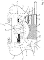
- FIG. 1 1 shows an example of a dome shaft 1 of an underground storage tank containing fuel, not shown here in full, with shaft walls 2 and a shaft bottom 3.
- the shaft bottom 3 is designed as a tank apex 5 of the underground storage tank.
- the dome shaft 1 sits directly on the top of the tank 5 here.
- the shaft walls 2 are essentially surrounded by soil 4 .
- Fittings in the form of pipelines 16 protrude from the shaft walls 2 into the dome shaft 1 .
- a manhole 17 with a tank cover 21 belonging to the earth storage tank rises from the shaft bottom 3 or the tank crown 5.
- the pipes 16 each lead out of one of the shaft walls 2 through the tank cover 21 of the manhole 17 into the earth storage tank.
- the shaft walls 2 each contact the tank crown 5 in an edge area 14 .
- the shaft walls 2 are here essentially at right angles to the tank crown 5.
- the shaft walls 2 also have corresponding transition areas 15, in which they merge into the pipelines 16 at a corresponding angle.
- defects 6 are formed in the tank crown 5 and one of the shaft walls 2 .
- the top of the tank has a defect 6 caused by corrosion, which allows liquids to penetrate into the outer shell of the underground storage tank.
- Corresponding defects 6 in one of the shaft walls 2 can also be seen, through which groundwater or seeping surface water can penetrate into the dome shaft 1 .
- the ground 4 is provided with a concrete seal 7.
- FIG. 1 further illustrates the schematic structure of a lining 10, with which the defects 6 can be repaired, so that operational reliability is provided.
- a first resin coating 18a This is followed by a carbon fiber mat 8, which is in operative connection on its underside with the first resin coating 18a.
- a second resin coating 18b is applied to the upper side of the carbon fiber mat 8 .
- Both resin coatings 18a,b are designed here as epoxy vinyl ester resins.
- a polymer coating 12 of about 2000 microns thickness is applied, which seals the aforementioned composite to the lining 10.
- the lining 10 or the carbon fiber mat 8 has, as shown in 1 in addition, in the above-mentioned transition area 15 from the tank crown 5 to the manhole 1, as well as in the edge area 14 between the tank crown 5 and the shaft wall 2, there is an upstand 11 in each case.
- the lining 10 is continuous in the area of the upstand 11, ie without interruption.
- the lining 10 is folded up in the corresponding areas up to a protective height S from here about 10 cm.
- the liner acts as a containment pan against spills, surface water, condensates and/or others Liquids, so that no chemicals, here for example fuel, can escape into the soil 4.
- the Domschacht 1 according to 1 has here, for example, a base area of approx. 0.9m ⁇ 0.9m in cross section.
- a carbon fiber mat with an area of approx. 1.00m 2 and approx ,b needed.
- the lining 10 is therefore liquid-tight and moreover chemically resistant, in particular to fuels (carburettor fuels, diesel).
- the carbon fiber mat strengthens the lining 10 in particular against mechanical stress.
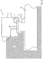
- FIG. 2 1 illustrates an example of a dome shaft 1 of an underground storage tank 20 according to one embodiment.
- the dome shaft 1 in turn has shaft walls 2 and a shaft bottom 3 .
- the dome shaft 1 is not seated here as shown Fig.1 on the top of the tank 5.
- the shaft bottom 3 is connected to the manhole 17 and is screwed to it via a tank cap 21 .
- the outer shell of the underground storage tank 20 is not in the immediate vicinity of the dome shaft 1.
- the bottom of the shaft 3 also has at least partial contact with the ground 4 downwards in the direction of the underground storage tank 20.
Landscapes
- Engineering & Computer Science (AREA)
- Manufacturing & Machinery (AREA)
- Mechanical Engineering (AREA)
- Application Of Or Painting With Fluid Materials (AREA)
- Underground Structures, Protecting, Testing And Restoring Foundations (AREA)
- Lining Or Joining Of Plastics Or The Like (AREA)
- Earth Drilling (AREA)
- Golf Clubs (AREA)
Applications Claiming Priority (1)
| Application Number | Priority Date | Filing Date | Title |
|---|---|---|---|
| DE102021101158.2A DE102021101158A1 (de) | 2021-01-20 | 2021-01-20 | Verfahren zur Sanierung eines Domschachts, sowie ein Domschacht |
Publications (5)
| Publication Number | Publication Date |
|---|---|
| EP4032684A2 true EP4032684A2 (fr) | 2022-07-27 |
| EP4032684A3 EP4032684A3 (fr) | 2022-09-21 |
| EP4032684C0 EP4032684C0 (fr) | 2024-10-02 |
| EP4032684B1 EP4032684B1 (fr) | 2024-10-02 |
| EP4032684B8 EP4032684B8 (fr) | 2024-11-06 |
Family
ID=80034908
Family Applications (1)
| Application Number | Title | Priority Date | Filing Date |
|---|---|---|---|
| EP22152181.8A Active EP4032684B8 (fr) | 2021-01-20 | 2022-01-19 | Procédé d'assainissement d'un puits de dôme et puits d'inspection |
Country Status (4)
| Country | Link |
|---|---|
| EP (1) | EP4032684B8 (fr) |
| DE (1) | DE102021101158A1 (fr) |
| ES (1) | ES3007136T3 (fr) |
| PL (1) | PL4032684T3 (fr) |
Family Cites Families (8)
| Publication number | Priority date | Publication date | Assignee | Title |
|---|---|---|---|---|
| DE3808553A1 (de) * | 1988-03-15 | 1989-10-05 | Hey Di Chemische Baustoffe Gmb | Verfahren zum abdichten eines schachtes fuer den einfuellstutzen eines unterirdischen tanks, insbesondere eines tanks fuer treibstoffe |
| JP2001030355A (ja) | 1999-05-20 | 2001-02-06 | Maeda Kosen Kk | 防食ライニング工法 |
| DE19946158A1 (de) | 1999-09-27 | 2001-03-29 | Siegfried Neis | Verfahren zum Sanieren von mit wassergefährdenden Stoffen in Berührung kommenden künstlichen Vertiefungen |
| DE20214501U1 (de) | 2002-09-19 | 2002-11-21 | Hellwig, Katja, 12205 Berlin | Domschacht |
| SG148831A1 (en) | 2004-05-25 | 2009-01-29 | Offshore Technology Dev Pte Lt | Protection and repair of structure surfaces with hand-laid composite materials |
| KR100758724B1 (ko) | 2006-06-27 | 2007-09-14 | 주식회사 한강개발 | 맨홀 보수공법 및 그 맨홀 보수부재 |
| DE102011109153A1 (de) | 2011-08-02 | 2013-02-07 | Wolfgang Schwab | Verfahren zum Abdichten von gemauerten oder betonierten Domschächten von Tankbehältern |
| NL2018980B1 (en) * | 2017-05-26 | 2018-12-07 | Wn Smitgroep | Method for renovating an underground hollow structure and material sheet for use in the method |
-
2021
- 2021-01-20 DE DE102021101158.2A patent/DE102021101158A1/de active Pending
-
2022
- 2022-01-19 EP EP22152181.8A patent/EP4032684B8/fr active Active
- 2022-01-19 ES ES22152181T patent/ES3007136T3/es active Active
- 2022-01-19 PL PL22152181.8T patent/PL4032684T3/pl unknown
Also Published As
| Publication number | Publication date |
|---|---|
| EP4032684C0 (fr) | 2024-10-02 |
| EP4032684B8 (fr) | 2024-11-06 |
| EP4032684A3 (fr) | 2022-09-21 |
| ES3007136T3 (en) | 2025-03-19 |
| PL4032684T3 (pl) | 2025-03-31 |
| EP4032684B1 (fr) | 2024-10-02 |
| DE102021101158A1 (de) | 2022-07-21 |
Similar Documents
| Publication | Publication Date | Title |
|---|---|---|
| EP4032684B1 (fr) | Procédé d'assainissement d'un puits de dôme et puits d'inspection | |
| DE3608950A1 (de) | Fluessigkeitsdichte und diffusionsdichte auskleidung von behaeltern | |
| DE102018110533B4 (de) | Sandwichlaminatstruktur, deren Verwendung und ein Verfahren zur Verwendung der Sandwichlaminatstruktur | |
| DE4109614C2 (de) | Hauseinführung für Versorgungsleitungen, insbesondere für Gasleitungen | |
| DE4429601A1 (de) | Verfahren zur Beschichtung von Leitungen und Schächten | |
| DE102004015694B4 (de) | Verbundmatte | |
| DE20104828U1 (de) | Verbindungssystem zur Befestigung einer flexiblen Kunststoffolie zur Leckschutzauskleidung an der Innenseite der Tankwandung eines Lagertanks | |
| DE10129807A1 (de) | Arbeitsverfahren zur Abdichtung von Leckagen in Flüssigkeiten führenden Rohren oder Flüssigkeiten enthaltenden Behältern | |
| DE1813342C3 (de) | Lagerbehalter z B fur Heizöl mit Innenwand sowie Verfahren zum nachträglichen Einbau der Innenwand | |
| DE102010040978A1 (de) | Bodenbeschichtung, auf Dichtigkeit prüfbarer Bodenbelag, Einrichtung zum Auffangen von Flüssigkeiten und Anordnung zum Galvanisieren sowie Verfahren zum Herstellen und zum Prüfen der Dichtigkeit | |
| DE4229829C2 (de) | Verfahren zur Sanierung eines Rohranschlusses an ein Betonbauwerk oder Fertigbauteil | |
| CH670123A5 (fr) | ||
| DE102021105112B4 (de) | Prüfanordnung und Verfahren zur Prüfung von Frischbetonverbundsystemen auf laterale Wasserbewegungen | |
| EP0986676B1 (fr) | Cuve collectrice | |
| DE3806480C2 (fr) | ||
| DE102004059223B4 (de) | Verfahren zum Reparieren eines Lecks in einer Behälter- oder Rohrwand für ein Druckmedium | |
| EP1426528B1 (fr) | Réservoir d'eau, ainsi que procédure de fabrication ou assainissement | |
| DE2949475A1 (de) | Feuchtigkeitsabdichtung fuer bauwerksflaechen von massivbauten | |
| DE10252867A1 (de) | Leckageboden und Verfahren zum Herstellen eines Leckagebodens | |
| DE19946158A1 (de) | Verfahren zum Sanieren von mit wassergefährdenden Stoffen in Berührung kommenden künstlichen Vertiefungen | |
| DE102011109153A1 (de) | Verfahren zum Abdichten von gemauerten oder betonierten Domschächten von Tankbehältern | |
| DD144683A1 (de) | Arbeitsoeffnung,insbesondere rohrdurchfuehrung in der wandung eines betontanks | |
| DE29603664U1 (de) | Korrosionsschutz-System für die Ummantelung von Schweißstellen an Stahlrohrleitungen für Erdbodendurchpressungen im Ramm- oder Drillbohrverfahren | |
| DE2731833C2 (fr) | ||
| EP0380492A1 (fr) | Procede pour la reparation sans demontage d'ouvrages d'art, d'objets, notamment d'egouts et de canalisations defectueux au niveau de la statique et de la retention d'eau |
Legal Events
| Date | Code | Title | Description |
|---|---|---|---|
| PUAI | Public reference made under article 153(3) epc to a published international application that has entered the european phase |
Free format text: ORIGINAL CODE: 0009012 |
|
| STAA | Information on the status of an ep patent application or granted ep patent |
Free format text: STATUS: THE APPLICATION HAS BEEN PUBLISHED |
|
| AK | Designated contracting states |
Kind code of ref document: A2 Designated state(s): AL AT BE BG CH CY CZ DE DK EE ES FI FR GB GR HR HU IE IS IT LI LT LU LV MC MK MT NL NO PL PT RO RS SE SI SK SM TR |
|
| PUAL | Search report despatched |
Free format text: ORIGINAL CODE: 0009013 |
|
| AK | Designated contracting states |
Kind code of ref document: A3 Designated state(s): AL AT BE BG CH CY CZ DE DK EE ES FI FR GB GR HR HU IE IS IT LI LT LU LV MC MK MT NL NO PL PT RO RS SE SI SK SM TR |
|
| RIC1 | Information provided on ipc code assigned before grant |
Ipc: B65D 90/10 20060101ALI20220818BHEP Ipc: B29C 63/48 20060101ALI20220818BHEP Ipc: B29C 63/30 20060101ALI20220818BHEP Ipc: B29C 63/00 20060101AFI20220818BHEP |
|
| STAA | Information on the status of an ep patent application or granted ep patent |
Free format text: STATUS: REQUEST FOR EXAMINATION WAS MADE |
|
| 17P | Request for examination filed |
Effective date: 20221121 |
|
| RBV | Designated contracting states (corrected) |
Designated state(s): AL AT BE BG CH CY CZ DE DK EE ES FI FR GB GR HR HU IE IS IT LI LT LU LV MC MK MT NL NO PL PT RO RS SE SI SK SM TR |
|
| GRAP | Despatch of communication of intention to grant a patent |
Free format text: ORIGINAL CODE: EPIDOSNIGR1 |
|
| STAA | Information on the status of an ep patent application or granted ep patent |
Free format text: STATUS: GRANT OF PATENT IS INTENDED |
|
| RIC1 | Information provided on ipc code assigned before grant |
Ipc: B65D 90/10 20060101ALI20240409BHEP Ipc: B29C 63/48 20060101ALI20240409BHEP Ipc: B29C 63/30 20060101ALI20240409BHEP Ipc: B29C 63/00 20060101AFI20240409BHEP |
|
| INTG | Intention to grant announced |
Effective date: 20240508 |
|
| GRAS | Grant fee paid |
Free format text: ORIGINAL CODE: EPIDOSNIGR3 |
|
| GRAA | (expected) grant |
Free format text: ORIGINAL CODE: 0009210 |
|
| STAA | Information on the status of an ep patent application or granted ep patent |
Free format text: STATUS: THE PATENT HAS BEEN GRANTED |
|
| AK | Designated contracting states |
Kind code of ref document: B1 Designated state(s): AL AT BE BG CH CY CZ DE DK EE ES FI FR GB GR HR HU IE IS IT LI LT LU LV MC MK MT NL NO PL PT RO RS SE SI SK SM TR |
|
| REG | Reference to a national code |
Ref country code: GB Ref legal event code: FG4D Free format text: NOT ENGLISH |
|
| REG | Reference to a national code |
Ref country code: DE Ref legal event code: R081 Ref document number: 502022001763 Country of ref document: DE Owner name: HEINE, KORNELIA AGNES, DE Free format text: FORMER OWNER: ANMELDERANGABEN UNKLAR / UNVOLLSTAENDIG, 80297 MUENCHEN, DE |
|
| REG | Reference to a national code |
Ref country code: CH Ref legal event code: PK Free format text: BERICHTIGUNG B8 Ref country code: CH Ref legal event code: EP |
|
| REG | Reference to a national code |
Ref country code: IE Ref legal event code: FG4D Free format text: LANGUAGE OF EP DOCUMENT: GERMAN |
|
| REG | Reference to a national code |
Ref country code: DE Ref legal event code: R096 Ref document number: 502022001763 Country of ref document: DE |
|
| RAP2 | Party data changed (patent owner data changed or rights of a patent transferred) |
Owner name: HEINE, KORNELIA AGNES |
|
| U01 | Request for unitary effect filed |
Effective date: 20241016 |
|
| U07 | Unitary effect registered |
Designated state(s): AT BE BG DE DK EE FI FR IT LT LU LV MT NL PT RO SE SI Effective date: 20241104 |
|
| REG | Reference to a national code |
Ref country code: SK Ref legal event code: T3 Ref document number: E 45531 Country of ref document: SK |
|
| U20 | Renewal fee for the european patent with unitary effect paid |
Year of fee payment: 4 Effective date: 20250123 |
|
| REG | Reference to a national code |
Ref country code: GR Ref legal event code: EP Ref document number: 20240403000 Country of ref document: GR Effective date: 20250211 |
|
| REG | Reference to a national code |
Ref country code: ES Ref legal event code: FG2A Ref document number: 3007136 Country of ref document: ES Kind code of ref document: T3 Effective date: 20250319 |
|
| PGFP | Annual fee paid to national office [announced via postgrant information from national office to epo] |
Ref country code: MC Payment date: 20250129 Year of fee payment: 4 |
|
| PG25 | Lapsed in a contracting state [announced via postgrant information from national office to epo] |
Ref country code: HR Free format text: LAPSE BECAUSE OF FAILURE TO SUBMIT A TRANSLATION OF THE DESCRIPTION OR TO PAY THE FEE WITHIN THE PRESCRIBED TIME-LIMIT Effective date: 20241002 |
|
| PGFP | Annual fee paid to national office [announced via postgrant information from national office to epo] |
Ref country code: IS Payment date: 20250120 Year of fee payment: 4 |
|
| PGFP | Annual fee paid to national office [announced via postgrant information from national office to epo] |
Ref country code: ES Payment date: 20250214 Year of fee payment: 4 |
|
| PGFP | Annual fee paid to national office [announced via postgrant information from national office to epo] |
Ref country code: IE Payment date: 20250119 Year of fee payment: 4 |
|
| PGFP | Annual fee paid to national office [announced via postgrant information from national office to epo] |
Ref country code: NO Payment date: 20250121 Year of fee payment: 4 |
|
| PGFP | Annual fee paid to national office [announced via postgrant information from national office to epo] |
Ref country code: GR Payment date: 20250120 Year of fee payment: 4 Ref country code: CH Payment date: 20250201 Year of fee payment: 4 |
|
| PGFP | Annual fee paid to national office [announced via postgrant information from national office to epo] |
Ref country code: CZ Payment date: 20250110 Year of fee payment: 4 |
|
| PGFP | Annual fee paid to national office [announced via postgrant information from national office to epo] |
Ref country code: SK Payment date: 20250110 Year of fee payment: 4 |
|
| PG25 | Lapsed in a contracting state [announced via postgrant information from national office to epo] |
Ref country code: RS Free format text: LAPSE BECAUSE OF FAILURE TO SUBMIT A TRANSLATION OF THE DESCRIPTION OR TO PAY THE FEE WITHIN THE PRESCRIBED TIME-LIMIT Effective date: 20250102 |
|
| PG25 | Lapsed in a contracting state [announced via postgrant information from national office to epo] |
Ref country code: SM Free format text: LAPSE BECAUSE OF FAILURE TO SUBMIT A TRANSLATION OF THE DESCRIPTION OR TO PAY THE FEE WITHIN THE PRESCRIBED TIME-LIMIT Effective date: 20241002 |
|
| PLBI | Opposition filed |
Free format text: ORIGINAL CODE: 0009260 |
|
| PLAX | Notice of opposition and request to file observation + time limit sent |
Free format text: ORIGINAL CODE: EPIDOSNOBS2 |
|
| 26 | Opposition filed |
Opponent name: KANIA, MICHAEL Effective date: 20250702 |
|
| PLBP | Opposition withdrawn |
Free format text: ORIGINAL CODE: 0009264 |
|
| REG | Reference to a national code |
Ref country code: CH Ref legal event code: L10 Free format text: ST27 STATUS EVENT CODE: U-0-0-L10-L00 (AS PROVIDED BY THE NATIONAL OFFICE) Effective date: 20251119 |
|
| PLBD | Termination of opposition procedure: decision despatched |
Free format text: ORIGINAL CODE: EPIDOSNOPC1 |
|
| PGFP | Annual fee paid to national office [announced via postgrant information from national office to epo] |
Ref country code: PL Payment date: 20251114 Year of fee payment: 5 |
|
| REG | Reference to a national code |
Ref country code: CH Ref legal event code: U11 Free format text: ST27 STATUS EVENT CODE: U-0-0-U10-U11 (AS PROVIDED BY THE NATIONAL OFFICE) Effective date: 20260201 |