EP4032486A1 - Vorrichtungen zur herstellung einer fistel - Google Patents
Vorrichtungen zur herstellung einer fistel Download PDFInfo
- Publication number
- EP4032486A1 EP4032486A1 EP22160431.7A EP22160431A EP4032486A1 EP 4032486 A1 EP4032486 A1 EP 4032486A1 EP 22160431 A EP22160431 A EP 22160431A EP 4032486 A1 EP4032486 A1 EP 4032486A1
- Authority
- EP
- European Patent Office
- Prior art keywords
- catheter
- variations
- electrode
- fistula
- catheters
- Prior art date
- Legal status (The legal status is an assumption and is not a legal conclusion. Google has not performed a legal analysis and makes no representation as to the accuracy of the status listed.)
- Pending
Links
Images


Classifications
-
- A—HUMAN NECESSITIES
- A61—MEDICAL OR VETERINARY SCIENCE; HYGIENE
- A61M—DEVICES FOR INTRODUCING MEDIA INTO, OR ONTO, THE BODY; DEVICES FOR TRANSDUCING BODY MEDIA OR FOR TAKING MEDIA FROM THE BODY; DEVICES FOR PRODUCING OR ENDING SLEEP OR STUPOR
- A61M1/00—Suction or pumping devices for medical purposes; Devices for carrying-off, for treatment of, or for carrying-over, body-liquids; Drainage systems
- A61M1/36—Other treatment of blood in a by-pass of the natural circulatory system, e.g. temperature adaptation, irradiation ; Extra-corporeal blood circuits
- A61M1/3621—Extra-corporeal blood circuits
- A61M1/3653—Interfaces between patient blood circulation and extra-corporal blood circuit
- A61M1/3655—Arterio-venous shunts or fistulae
-
- A—HUMAN NECESSITIES
- A61—MEDICAL OR VETERINARY SCIENCE; HYGIENE
- A61B—DIAGNOSIS; SURGERY; IDENTIFICATION
- A61B18/00—Surgical instruments, devices or methods for transferring non-mechanical forms of energy to or from the body
- A61B18/04—Surgical instruments, devices or methods for transferring non-mechanical forms of energy to or from the body by heating
- A61B18/12—Surgical instruments, devices or methods for transferring non-mechanical forms of energy to or from the body by heating by passing a current through the tissue to be heated, e.g. high-frequency current
- A61B18/14—Probes or electrodes therefor
- A61B18/1492—Probes or electrodes therefor having a flexible, catheter-like structure, e.g. for heart ablation
-
- A—HUMAN NECESSITIES
- A61—MEDICAL OR VETERINARY SCIENCE; HYGIENE
- A61B—DIAGNOSIS; SURGERY; IDENTIFICATION
- A61B17/00—Surgical instruments, devices or methods
- A61B17/32—Surgical cutting instruments
- A61B17/320016—Endoscopic cutting instruments, e.g. arthroscopes, resectoscopes
-
- A—HUMAN NECESSITIES
- A61—MEDICAL OR VETERINARY SCIENCE; HYGIENE
- A61B—DIAGNOSIS; SURGERY; IDENTIFICATION
- A61B17/00—Surgical instruments, devices or methods
- A61B17/32—Surgical cutting instruments
- A61B17/3205—Excision instruments
- A61B17/3207—Atherectomy devices working by cutting or abrading; Similar devices specially adapted for non-vascular obstructions
- A61B17/320725—Atherectomy devices working by cutting or abrading; Similar devices specially adapted for non-vascular obstructions with radially expandable cutting or abrading elements
-
- A—HUMAN NECESSITIES
- A61—MEDICAL OR VETERINARY SCIENCE; HYGIENE
- A61B—DIAGNOSIS; SURGERY; IDENTIFICATION
- A61B18/00—Surgical instruments, devices or methods for transferring non-mechanical forms of energy to or from the body
- A61B18/04—Surgical instruments, devices or methods for transferring non-mechanical forms of energy to or from the body by heating
- A61B18/12—Surgical instruments, devices or methods for transferring non-mechanical forms of energy to or from the body by heating by passing a current through the tissue to be heated, e.g. high-frequency current
- A61B18/14—Probes or electrodes therefor
- A61B18/16—Indifferent or passive electrodes for grounding
-
- A—HUMAN NECESSITIES
- A61—MEDICAL OR VETERINARY SCIENCE; HYGIENE
- A61B—DIAGNOSIS; SURGERY; IDENTIFICATION
- A61B17/00—Surgical instruments, devices or methods
- A61B2017/00743—Type of operation; Specification of treatment sites
- A61B2017/00778—Operations on blood vessels
-
- A—HUMAN NECESSITIES
- A61—MEDICAL OR VETERINARY SCIENCE; HYGIENE
- A61B—DIAGNOSIS; SURGERY; IDENTIFICATION
- A61B17/00—Surgical instruments, devices or methods
- A61B2017/00831—Material properties
- A61B2017/00876—Material properties magnetic
-
- A—HUMAN NECESSITIES
- A61—MEDICAL OR VETERINARY SCIENCE; HYGIENE
- A61B—DIAGNOSIS; SURGERY; IDENTIFICATION
- A61B17/00—Surgical instruments, devices or methods
- A61B17/22—Implements for squeezing-off ulcers or the like on inner organs of the body; Implements for scraping-out cavities of body organs, e.g. bones; for invasive removal or destruction of calculus using mechanical vibrations; for removing obstructions in blood vessels, not otherwise provided for
- A61B2017/22094—Implements for squeezing-off ulcers or the like on inner organs of the body; Implements for scraping-out cavities of body organs, e.g. bones; for invasive removal or destruction of calculus using mechanical vibrations; for removing obstructions in blood vessels, not otherwise provided for for crossing total occlusions, i.e. piercing
- A61B2017/22095—Implements for squeezing-off ulcers or the like on inner organs of the body; Implements for scraping-out cavities of body organs, e.g. bones; for invasive removal or destruction of calculus using mechanical vibrations; for removing obstructions in blood vessels, not otherwise provided for for crossing total occlusions, i.e. piercing accessing a blood vessel true lumen from the sub-intimal space
-
- A—HUMAN NECESSITIES
- A61—MEDICAL OR VETERINARY SCIENCE; HYGIENE
- A61B—DIAGNOSIS; SURGERY; IDENTIFICATION
- A61B17/00—Surgical instruments, devices or methods
- A61B17/32—Surgical cutting instruments
- A61B17/3205—Excision instruments
- A61B17/3207—Atherectomy devices working by cutting or abrading; Similar devices specially adapted for non-vascular obstructions
- A61B17/320783—Atherectomy devices working by cutting or abrading; Similar devices specially adapted for non-vascular obstructions through side-hole, e.g. sliding or rotating cutter inside catheter
- A61B2017/320791—Atherectomy devices working by cutting or abrading; Similar devices specially adapted for non-vascular obstructions through side-hole, e.g. sliding or rotating cutter inside catheter with cutter extending outside the cutting window
-
- A—HUMAN NECESSITIES
- A61—MEDICAL OR VETERINARY SCIENCE; HYGIENE
- A61B—DIAGNOSIS; SURGERY; IDENTIFICATION
- A61B18/00—Surgical instruments, devices or methods for transferring non-mechanical forms of energy to or from the body
- A61B2018/00053—Mechanical features of the instrument of device
- A61B2018/00059—Material properties
- A61B2018/00071—Electrical conductivity
- A61B2018/00083—Electrical conductivity low, i.e. electrically insulating
-
- A—HUMAN NECESSITIES
- A61—MEDICAL OR VETERINARY SCIENCE; HYGIENE
- A61B—DIAGNOSIS; SURGERY; IDENTIFICATION
- A61B18/00—Surgical instruments, devices or methods for transferring non-mechanical forms of energy to or from the body
- A61B2018/00053—Mechanical features of the instrument of device
- A61B2018/00107—Coatings on the energy applicator
-
- A—HUMAN NECESSITIES
- A61—MEDICAL OR VETERINARY SCIENCE; HYGIENE
- A61B—DIAGNOSIS; SURGERY; IDENTIFICATION
- A61B18/00—Surgical instruments, devices or methods for transferring non-mechanical forms of energy to or from the body
- A61B2018/00053—Mechanical features of the instrument of device
- A61B2018/00172—Connectors and adapters therefor
-
- A—HUMAN NECESSITIES
- A61—MEDICAL OR VETERINARY SCIENCE; HYGIENE
- A61B—DIAGNOSIS; SURGERY; IDENTIFICATION
- A61B18/00—Surgical instruments, devices or methods for transferring non-mechanical forms of energy to or from the body
- A61B2018/00315—Surgical instruments, devices or methods for transferring non-mechanical forms of energy to or from the body for treatment of particular body parts
- A61B2018/00345—Vascular system
- A61B2018/00404—Blood vessels other than those in or around the heart
-
- A—HUMAN NECESSITIES
- A61—MEDICAL OR VETERINARY SCIENCE; HYGIENE
- A61B—DIAGNOSIS; SURGERY; IDENTIFICATION
- A61B18/00—Surgical instruments, devices or methods for transferring non-mechanical forms of energy to or from the body
- A61B2018/00571—Surgical instruments, devices or methods for transferring non-mechanical forms of energy to or from the body for achieving a particular surgical effect
- A61B2018/00577—Ablation
-
- A—HUMAN NECESSITIES
- A61—MEDICAL OR VETERINARY SCIENCE; HYGIENE
- A61B—DIAGNOSIS; SURGERY; IDENTIFICATION
- A61B18/00—Surgical instruments, devices or methods for transferring non-mechanical forms of energy to or from the body
- A61B2018/00571—Surgical instruments, devices or methods for transferring non-mechanical forms of energy to or from the body for achieving a particular surgical effect
- A61B2018/00625—Vaporization
-
- A—HUMAN NECESSITIES
- A61—MEDICAL OR VETERINARY SCIENCE; HYGIENE
- A61B—DIAGNOSIS; SURGERY; IDENTIFICATION
- A61B18/00—Surgical instruments, devices or methods for transferring non-mechanical forms of energy to or from the body
- A61B18/04—Surgical instruments, devices or methods for transferring non-mechanical forms of energy to or from the body by heating
- A61B18/12—Surgical instruments, devices or methods for transferring non-mechanical forms of energy to or from the body by heating by passing a current through the tissue to be heated, e.g. high-frequency current
- A61B18/1206—Generators therefor
- A61B2018/1246—Generators therefor characterised by the output polarity
- A61B2018/1253—Generators therefor characterised by the output polarity monopolar
-
- A—HUMAN NECESSITIES
- A61—MEDICAL OR VETERINARY SCIENCE; HYGIENE
- A61B—DIAGNOSIS; SURGERY; IDENTIFICATION
- A61B18/00—Surgical instruments, devices or methods for transferring non-mechanical forms of energy to or from the body
- A61B18/04—Surgical instruments, devices or methods for transferring non-mechanical forms of energy to or from the body by heating
- A61B18/12—Surgical instruments, devices or methods for transferring non-mechanical forms of energy to or from the body by heating by passing a current through the tissue to be heated, e.g. high-frequency current
- A61B18/14—Probes or electrodes therefor
- A61B2018/1405—Electrodes having a specific shape
- A61B2018/144—Wire
-
- A—HUMAN NECESSITIES
- A61—MEDICAL OR VETERINARY SCIENCE; HYGIENE
- A61B—DIAGNOSIS; SURGERY; IDENTIFICATION
- A61B90/00—Instruments, implements or accessories specially adapted for surgery or diagnosis and not covered by any of the groups A61B1/00 - A61B50/00, e.g. for luxation treatment or for protecting wound edges
- A61B90/39—Markers, e.g. radio-opaque or breast lesions markers
- A61B2090/3925—Markers, e.g. radio-opaque or breast lesions markers ultrasonic
-
- A—HUMAN NECESSITIES
- A61—MEDICAL OR VETERINARY SCIENCE; HYGIENE
- A61B—DIAGNOSIS; SURGERY; IDENTIFICATION
- A61B90/00—Instruments, implements or accessories specially adapted for surgery or diagnosis and not covered by any of the groups A61B1/00 - A61B50/00, e.g. for luxation treatment or for protecting wound edges
- A61B90/39—Markers, e.g. radio-opaque or breast lesions markers
- A61B2090/3966—Radiopaque markers visible in an X-ray image
Definitions
- the current invention relates to devices and methods for forming a fistula.
- the devices and methods may be used to form a fistula between two blood vessels.
- a fistula is generally a passageway formed between two internal organs. Forming a fistula between two blood vessels can have one or more beneficial functions. For example, the formation of a fistula between an artery and a vein may provide access to the vasculature for hemodialysis patients. Specifically, forming a fistula between an artery and a vein allows blood to flow quickly between the vessels while bypassing the capillaries. Needles, catheters, or other cannulas may then be inserted into the blood vessels near the fistula to draw blood from the circulatory system, pass it through a dialysis machine, and return it to the body. The quickened flow provided by the fistula may provide for effective hemodialysis. In a mature fistula, the flow rate through the fistula may be on the order of 300-500 ml/min, or may be on the order of 300-1500 ml/min, or more.
- a fistula may be formed between two veins to form a veno-venous fistula.
- a veno-venous fistula may be used to help treat portal venous hypertension.
- cirrhosis or other liver diseases may cause increased resistance to flow through the portal veins draining from the intestine to the liver. This increased resistance may cause massive dilation of blood vessels, which may rupture spontaneously.
- a fistula may be formed between a portal vein and one of the major branches, thereby lowering venous pressure in the portal vein. As such, it may be useful to find improved ways to form a fistula between two blood vessels.
- the devices described here comprise one or more catheters.
- Each catheter generally comprises a distal end, an intermediate portion, and a proximal end.
- the proximal end of the catheter may comprise one or more handles or adaptors, which may be used to control or manipulate the catheter.
- the handle or adaptor may comprise one or more ports for introducing devices (e.g., electrical leads, guidewires) or substances (e.g., contrast fluid, perfusion fluid, or the like) into the catheter.
- the handle or adaptor may additionally comprise one or more alignment projections that may be used to help align one catheter relative to another catheter.
- the catheters may comprise one or more alignment elements to help align one catheter relative to another or relative to an anatomical structure.
- the alignment elements may be any suitable element or structure that may help align one or more catheters in one or more blood vessels.
- one or more of the alignment elements may comprise one or more magnetic alignment elements.
- the magnetic alignment elements may be used to help advance a catheter through the vasculature, may be used to draw two or more catheters closer together within the vasculature, or may be used to axially and/or rotationally align two or more catheters.
- Magnetic alignment elements may or may not be organized into one or more arrays, and each magnetic alignment element may have any suitable size or shape.
- one or more magnetic alignment elements may be semi-cylindrical, cylindrical, or annular-shaped. In other variations, one or more alignment elements may be bar-, billet-, or box-shaped.
- the catheters may comprise one or more markers.
- the marker may be directly visualized.
- the catheters may comprise one or more marker bands along a portion thereof.
- the marker may be indirectly visualized (e.g., via fluoroscopy, x-ray, or ultrasound visualization).
- the device may comprise one or more marker bands that may allow for rotational alignment of one or more catheters.
- a catheter may comprise one or more elements for forming a fistula between vessels.
- the fistula-forming element may be any mechanism suitable for forming a perforation between two blood vessels.
- the catheter may comprise one or more mechanical cutting elements, such as, for example, a blade, a needle, a lancet, or the like.
- the catheter may comprise one or more electrodes for ablating or otherwise vaporizing tissue between two blood vessels.
- the electrodes comprise one or more ablation surfaces for ablating tissues.
- the ablation surface is flush with the surface of the catheter.
- the ablation surface may project from the surface of the catheter.
- the ablation surface may be recessed relative to the surface of the catheter.
- the ablation surface may be adjustable relative to the surface of the catheter.
- a catheter may comprise one or more expandable structures.
- the catheter may comprise any number of expandable structures (e.g., zero, one, two, or three or more), and each expandable structure may be any suitable expandable structure (e.g., a balloon, an expandable cage, mesh, or the like).
- the expandable structure or expandable structures may be used to help place the catheter in apposition with a tissue wall.
- one or more expandable structures may be used to dilate one or more portions of a blood vessel.
- one or more expandable structures may be used to expand or otherwise modify the size of a fistula.
- an expandable structure may comprise one or more electrodes that may be activated to deliver RF energy to one or more blood vessels, which may restrict blood flow therethrough. Additionally or alternatively, an expandable structure may help to anchor a catheter at least temporarily at certain position within the vasculature.
- a catheter may comprise one or more components for joining or otherwise fixing a portion of a first blood vessel to a second blood vessel.
- a catheter may comprise one or more components (e.g., an electrode) configured to supply electrical, ultrasound, or laser energy to tissue.
- a catheter may comprise one or more needles configured to deliver an adhesive between a first blood vessel and a second blood vessel.
- a catheter may be configured to deploy one or more barbs, staples, or other implants into tissue of the first and second blood vessels.
- the devices and methods may be used to form a fistula between two blood vessels (e.g., an arteriovenous fistula between an artery and a vein or a veno-venous fistula between two veins).
- a fistula between two blood vessels e.g., an arteriovenous fistula between an artery and a vein or a veno-venous fistula between two veins.
- one or more catheters are advanced in a minimally invasive fashion through the vasculature to a target location.
- a single catheter may be placed in a blood vessel to form a fistula with an adjoining blood vessel.
- a system comprising multiple catheters may be used to form a fistula.
- a catheter may be placed in each of the two blood vessels.
- each catheter may or may not have the same configuration of elements, and that some catheters may be different from and/or complementary to other catheters, as will be described in more detail below.
- each catheter will have a proximal end, a distal end, and an intermediate portion connecting the proximal and distal ends.
- the proximal end may comprise one or more adaptors or handles, which may be utilized to help aid in advancement, positioning and control of the catheter within the vasculature, and may further be used to actuate one or more components of the catheter and/or introduce one or more fluids or substances into and/or through the catheter.
- the catheter may comprise one or more elements that may aid in fistula formation.
- one or more portions (e.g., the distal end and/or the intermediate portion) of the catheter may comprise one or more alignment elements (e.g., one or more magnets) that may help align the catheter with another catheter positioned in a related blood vessel and/or bring the catheters (and blood vessels) in closer approximation.
- one or more portions (e.g., the distal end and/or an intermediate portion) of the catheter may comprise one or more mechanisms for forming a fistula.
- the catheters may additionally comprise one or more lumens or passageways extending at least partially along or through the catheter, and may be used to pass one or more guidewires, one or more drugs or fluids (e.g., contrast agents, perfusion fluids), combinations thereof, or the like at least partially along or through the catheter.
- the distal tip of the catheter may be configured to aid in advancement of the catheter and/or to be atraumatic.
- the tip may comprise one or more rapid exchange portions or other lumens for advancement of the catheter over a guidewire.
- the tip portion may have a guidewire attached to or otherwise integrally formed with the catheter.
- the catheters may further comprise one or more external expandable elements (e.g., a balloon, expandable cage, mesh, or the like) that may help position a catheter within a blood vessel.
- the one or more expandable elements may affect the flow of blood through one or more blood vessels (e.g., by temporarily occluding blood flow through the blood vessel, dilating one or more portions of a blood vessel, constricting one or more portions of a blood vessel, or the like).
- one or more expandable elements may act to temporarily anchor a portion of the catheter relative to a blood vessel.
- the catheter comprises one or more shape-changeling elements
- the use of an expandable element to temporarily anchor a portion of the catheter relative to a blood vessel may aid in altering the shape of the catheter.
- the catheters described here may have any combination of the aforementioned elements, each of which will be described in more detail below.
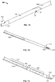
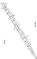
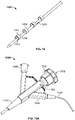
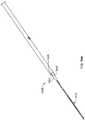
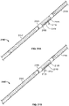
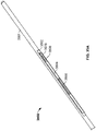
- FIGS. 1A-1C depict an illustrative variation of a catheter (100) suitable for use in forming a fistula.
- FIG. 1A depicts a perspective view of distal portion (108) of catheter (100) with sleeve (106) covering at least a portion of the catheter (100).
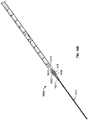
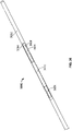
- FIG. 1B depicts a partially-transparent view of catheter (100) with sleeve (106) illustrated as partially transparent.
- FIG. 1C depicts a partially-perspective view of catheter (100) with sleeve (106) and the catheter body illustrated as partially transparent.
- catheter (100) may comprise electrode (102) having an exposed ablation surface (105) and a lead wire (104) attached thereto.
- ablation surface (105) of electrode (102) may be placed in electrical contact with a target tissue, and a current may be supplied to the electrode (102) to ablate or vaporize tissue.
- the catheters described here may comprise one or more elements for forming a fistula.
- These fistula-forming elements may utilize any structure or mechanism capable of cutting, ablating, vaporizing, dissolving, or otherwise removing tissue between adjoining vessels, such as, for example, one or more electrical mechanisms (e.g., one or more electrodes or electrocautery devices), one or more mechanical mechanisms (e.g., one or more cutting blades, lancets, needles, or the like), one or more chemical mechanisms (e.g., one or more enzyme-releasing devices), cryogenic-cautery devices, laser ablation devices (e.g., one or more fiber-optic laser light sources), combinations thereof or the like.
- electrical mechanisms e.g., one or more electrodes or electrocautery devices
- mechanical mechanisms e.g., one or more cutting blades, lancets, needles, or the like
- chemical mechanisms e.g., one or more enzyme-releasing devices
- cryogenic-cautery devices e.
- a catheter may have any suitable number (e.g., zero, one, two, three, or four or more) and combination of these fistula-forming elements, and these fistula-forming elements may be located in or on any suitable portion of the catheter (e.g., the distal end, an intermediate portion, combinations thereof).
- a catheter comprises two or more fistula-forming elements
- multiple fistula-forming elements may form multiple fistulas, simultaneously or sequentially.
- multiple fistula-forming elements may interact to form a single fistula.
- each catheter may comprise a fistula-forming element, but need not. Indeed, in some of these variations, only one catheter may comprise a fistula-forming element. In some of these instances, the other catheter may still help align the catheters and/or approximate the blood vessels, but may not directly contribute to tissue removal. In variations where multiple catheters each comprises a fistula-forming element, the catheters may have complimentary fistula-forming elements. For example, in variations where two or more catheters comprise electrodes, as explained in more detail below, one catheter may comprise an electrode that acts as an active electrode, while another catheter may comprise an electrode that acts as a passive or ground electrode.
- a catheter may comprise one or more electrodes for use in forming a fistula.
- a catheter may comprise an electrode body and at least one lead wire or other conductor attached thereto for connecting the electrode to an electrosurgical generator.
- one or more portions of a lead wire may act as an electrode to ablate tissue.
- a catheter may have any suitable number of electrodes (e.g., zero, one, two, or three or more), and each electrode may be positioned at any suitable point along the catheter's length (i.e., the distal end, an intermediate portion, etc.), and may have any suitable size and shape, as discussed in more detail below.
- an electrode when used with a direct current generator, an electrode may either act as an active electrode (e.g., in which current is supplied to the electrode to ablate tissue) or a passive ground electrode (e.g., in which current is carried away from the electrode to a grounded location), depending on the manner in which it is used.
- an active electrode e.g., in which current is supplied to the electrode to ablate tissue
- a passive ground electrode e.g., in which current is carried away from the electrode to a grounded location
- one or more electrodes may be connected to an electrosurgical generator, power supply, or other waveform generator that is configured to generate an alternating current.
- two or more electrodes may be connected to the bipolar outputs of a generator.
- one or more electrodes may be connected to a monopolar output of a generator.
- a first electrode is attached to the active output of the generator, and a return electrode (e.g., a large metal plate or flexible metalized pad) may be temporarily attached or affixed to the patient and connected to the return output of the generator.
- two or more electrodes may be attached to an active output of the generator, and a return electrode may be temporarily attached or affixed to the patient and connected to the return output of the generator.
- a first electrode may be attached to the active output of the generator, and a second electrode may be attached to the return output of the generator in a "focus monopolar" configuration.
- each electrode may be exposed to the surrounding environment (e.g., through one or more apertures or openings in the catheter body).
- This exposed surface may be configured to contact surrounding tissue (e.g., a blood vessel wall) or fluids, and may act as an ablation surface such that current may be supplied to and/or carried from tissue via the ablation surface to facilitate ablation or vaporization of tissue.
- the ablation surface may be temporarily covered (e.g., by a sheath or tubing) such that the ablation surface does not contact tissue. In these instances, the temporary covering may be moved or removed to expose the ablation surface to the surrounding environment.
- the ablation surface may be temporarily recessed or held within the catheter, and in some of these instances may be advanced out of the catheter to contact tissue.
- the ablation surface need not be movable, and may instead be fixed relative to the catheter.
- an exposed electrode surface may comprise a porous coating that allows conduction of current thereto or therefrom while preventing direct contact between two electrodes, as will be described in more detail below.
- the electrodes may be made from any suitable material or combination of materials.
- the electrode may comprise one or more refractory metals.
- an electrode may comprise tungsten, molybdenum, niobium, tantalum, rhenium, combinations or alloys thereof.
- the electrode ablation surface may have any shape or size suitable for ablating tissue.
- the ablation surface may be oval-shaped, circular, rectangular, triangular, pentagonal, hexagonal, polygonal, irregularly shaped, or the like.
- the ablation surface may be roughened or otherwise patterned, as will be described in more detail below.
- these apertures or openings may at least partially define the size and shape of the ablation surface.
- the catheter comprises a nesting material, as will be described in more detail below, the nesting material may at least partially define the size and shape of the ablation surface.
- the size and shape of the ablation surface may help determine the size and shape of the resulting fistula.
- the ablation surface may have any suitable length (e.g., about 0.0625 in, about 0.1875 in, between about 0.05 in and about 0.2 in, between about 0.05 in and about 0.075 in, between about 0.15 in and about 0.2 in, and the like) and any suitable width (e.g., about 0.0313 in., about 0.0625 in, between about 0.025 in and about 0.075 in, between about 0.025 and about 0.05 in, between about 0.05 and about 0.075 in, and the like).
- the ablation surface may have any suitable radius (e.g., about 0.03 in, about 0.04 in, about 0.05 in, and the like).
- the ablation surface may have any suitable height (e.g., about .25 mm, about .5 mm, about .75 mm, about 1 mm, between about .1 and about 1.5 mm, between about .25 and about 1 mm, between about .25 and about .75 mm, greater than about 1.5 mm, or the like).
- the two or more electrodes may have different sizes.
- a first electrode having a larger ablation surface e.g., a rectangular ablation surface of about 0.2 inches by about 0.05 inches
- a second electrode having a smaller ablation surface e.g., a rectangular ablation surface of about 0.1 inches by about 0.05 inches
- the second electrode when an RF signal (e.g., a sinusoidal waveform, or the like) of a certain power (e.g., 40 W) is applied to the electrodes to form a fistula between the artery and the vein, the second electrode may have a larger current density than the first electrode by virtue of its smaller ablation surface. This may cause the formation of the fistula to begin in the vein, and propagate through the artery.
- a certain power e.g. 40 W
- fistula may help prevent extravasation (e.g., blood loss to surrounding tissue) in instances where a fistula is not fully formed between an artery and a vein (as partial fistula formation beginning in an artery may have a greater risk of extravasation than partial fistula formation beginning an a vein).
- extravasation e.g., blood loss to surrounding tissue
- the ablation surface may be flush with an outer surface of the catheter body.
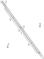
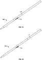
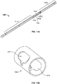
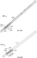
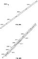
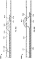
- FIG. 2 illustrates one such variation of catheter (200) comprising an electrode body (202) having ablation surface (205). Also shown there are lead wire (204), proximal anchoring magnet (206), and distal anchoring magnet (208). As shown in FIG. 2 , ablation surface (205) may be exposed through catheter (200), and may be substantially flush with the outer surface of catheter (200). While shown in FIG. 2 as having a cylindrical electrode body (202) with a rounded rectangular ablation surface (205), it should be appreciated that electrode body (202) may have any suitably-shaped ablation surface (205), such as those mentioned above. While catheter (200) is shown in FIG. 2 as comprising a proximal (206) and a distal (208) anchoring magnet, it should be appreciated that catheter (200) may have any alignment elements or combinations of alignment elements as described in more detail below, or may not comprise any alignment elements.
- ablation surface (205) may be flush with catheter (200), and thus may have a rounded surface.
- a catheter may comprise an electrode where one or more portions of the ablation surface may be flat.
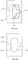
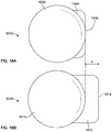
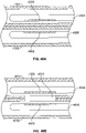
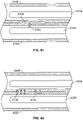
- FIGS. 18A and 18B illustrate end views two variations of catheters having flat ablation surfaces.
- FIG. 18A shows a first variation of catheter (1800) comprising a catheter body (1802) and an electrode (1804) comprising a flat ablation surface (1806).
- a flat ablation surface (1806) may help provide better tissue apposition between the electrode (1804) and tissue (not shown).
- the two ablation surfaces may cause vessel tissue to at least temporarily flatten therebetween. This may increase the electrical isolation of the flattened tissue (e.g., current supplied to an active electrode will be more likely to pass through the flattened tissue as it travels to the ground electrode, rather than be lost to other fluids or surrounding tissue), which may aid in fistula formation.
- FIG. 18A shows another variation of ablation surface (1808) comprising a catheter body (1810) and an electrode (1812) comprising a flat ablation surface (1814). As shown there, the plane of the ablation surface (1814) may protrude a distance (x) from the catheter body (1810).
- This distance (x) may be any suitable distance, such as, for example about .25 mm, about .5 mm, about .75 mm, about 1 mm, between about .1 and about 1.5 mm, between about .25 and about 1 mm, between about .25 and about .75 mm, or the like.
- a protruding ablation surface (1814) may press into tissue as catheter (1808) is brought toward another catheter, which may help increase tissue apposition with the ablation surface, which may aid in tissue ablation.
- the electrode may be configured such that distance (x) is adjustable.
- one or more portions of the device e.g., a rod, lead wire, or other actuation mechanism
- the protrusion of the device may be any suitable distance, such as, for example about .25 mm, about .5 mm, about .75 mm, about 1 mm, between about .1 and about 1.5 mm, between about .25 and about 1 mm, between about .25 and about .75
- distance (x) may be adjustable between about 0 mm and about 1.5 mm, between about 0 mm and about 1.0 mm, between about 0 mm and about 0.5 mm, between about 0.25 mm and about 0.75 mm and the like. It should also be appreciated that the ablation surface may be configured to move from a recessed position and a protruding position.
- FIG. 28A shows a first variation of electrode (2800) comprising a surface (2802).
- surface (2802) may be flat, and may be made from a conductive material.
- Surface (2802) may act as an ablation surface when electrode (2800) is used with one or more of the catheters described here.
- FIG. 28B shows a variation of catheter (2804) comprising electrode (2800) at least partially housed in a nesting material (2806) within catheter body (2808).
- surface (2802) may act as an ablation surface. It should be appreciated while shown in FIG.
- catheter (2804) may comprise any suitable alignment elements or combination of alignment elements as described in more detail below.
- FIG. 29A shows a second variation of an electrode (2900) comprising a patterned surface (2902).
- electrode (2900) may comprise a body (2904) made from a conductive material.
- a first side of body (2904) may comprise a plurality of channels (2906) which may define a plurality of projections (2908), each having a raised surface (2910).
- Channels (2906) may be at least partially filled with a non-conductive encapsulant material (not shown) such as, for example, one or more ceramic materials, parylene, one or more polymeric resins (e.g., polyetherimide, polyetheretherketone, one or more phenolic resins, or the like), silica, one or more metal oxides (e.g., aluminum oxide), combinations thereof, and the like.
- a non-conductive encapsulant material such as, for example, one or more ceramic materials, parylene, one or more polymeric resins (e.g., polyetherimide, polyetheretherketone, one or more phenolic resins, or the like), silica, one or more metal oxides (e.g., aluminum oxide), combinations thereof, and the like.
- a non-conductive encapsulant material such as, for example, one or more ceramic materials, parylene, one or more polymeric resins (e.g., polyetherimide, polyetheretherketone, one or more phenolic
- an encapsulant material (2914) may fill the channels of the electrode (2900) such that the encapsulant material (2914) and raised surfaces (2910) form a flat patterned surface (2902).
- Patterned surface (2902) may be exposed through catheter body (2915), and may act as an ablation surface, as will be described immediately below.
- catheter (2912) may comprise any suitable alignment elements or combination of alignment elements as described in more detail below.
- the raised surfaces (2910) of projections (2908) may be capable of conducting electrical energy to tissue, while the encapsulant material (2914) may prevent or resist the flow of energy therethrough. Since only a portion of the patterned surface (2902) may be conductive via raised surfaces (2910), the effective electrode area provided by patterned surface (2902) is decreased. When a power output is applied to an electrode, the decreased effective electrode area may increase the current density on the conductive portions of the electrode (e.g., the conductive raised surfaces (2910) of electrode (2900). Current may build on the edges of the raised surfaces (2910), and the increased current density may promote current arcing between electrodes, which may aid in the ablation or vaporization of tissue.
- the projections (2908) may have any suitable cross-section shape or shapes, such as, for example, rectangles, trapezoids, circles, ovals, polygons, shapes with irregular geometry, or the like.
- Projections (2908) and channels (2906) may be formed in any suitable manner.
- one or more channels may be formed (e.g., by cutting, etching, carving, or the like) in a block of material (such as electrode (2800) described above in regards to FIGS. 28A and 28B ) to define projections (2908).
- one or more projections may be formed separately from a base member, and then may be attached to the base member.
- the flat ablation surface may have any suitable cross-sectional shape (e.g., a circle, oval, triangle, square, rectangle, pentagon, hexagon, other polygon, irregular shape, or the like). Additionally or alternatively, the ablation surface may be patterned, such as described in more detail above.
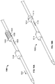
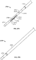
- FIG. 3 shows one variation of catheter (300) comprising an electrode body (310) with a hexagonal ablation surface (311) protruding from catheter (300). Also shown there are proximal anchoring magnet (302), distal anchoring magnet (304), lumen (308), and concentric electric conductor (314), each of which will be described in more detail below. Additionally, while flat ablation surfaces (1806) and (1814) are shown in FIGS.
- a flat ablation surface may be angled relative to a catheter body.
- electrode may have an ablation surface that protrudes from the catheter body but does not comprise a flat surface.
- ablation surface (103) of catheter (100) illustrated in FIGS. 1A-1C and described in more detail above the ablation surface may be hemispherical.
- one or more portions of the catheter may taper to help reduce trauma that may be caused by the protruding ablation surface (or edges thereof) as a catheter is advanced through a blood vessel.
- the ablation surface itself may be tapered.
- one or more additional components such as the catheter body or an electrode nesting material (as will be described in more detail below), may taper to the ablation surface.
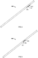
- FIG. 4 depicts a variation catheter (400) comprising an electrode (402) having an ablation surface (404) protruding from the surface of the catheter (400). Also shown there is nesting material (406) partially covering the electrode (402). As shown in FIG. 4 , nesting material (406) may taper from the surface of catheter (400) to ablation surface (404), which may help minimize tissue trauma.
- one or more portions of an electrode may be at least partially covered or housed by a nesting material. Indeed, in some of these variations the entire electrode body except for the ablation surface is covered by a nesting material.
- the nesting material may serve a number of useful purposes. As described immediately above, the nesting material may help prevent damage done by the electrode to tissue as the catheter is advanced through a blood vessel. In some variations, the nesting material may hold an electrode in place relative to one or more other elements of a catheter (e.g., one or more alignment elements, or the like). Additionally, in some instances, the nesting material may insulate the electrode body from surrounding tissue or other portions of the catheter, which may protect or shield the other portions of the catheter.
- thermal insulation provided by the nesting material may protect other catheter components from heat that may be generated by the electrode. Additionally or alternatively, electrical insulation provided by the nesting material may help minimize current loss to other parts of the catheter or surrounding tissue.
- the nesting material may be made of any heat and/or electrically resistant materials. Examples of suitable nesting materials include, but are not limited to, ceramic materials, parylene, one or more polymeric resins (e.g., polyetherimide, polyetheretherketone, one or more phenolic resins, or the like), silica, one or more metal oxides (e.g., aluminum oxide), combinations thereof, or the like. In some instances, the nesting material may be a machined solid or may be molded.
- the nesting material may be plasma-sprayed, coated or otherwise deposited on one or more portions of the electrode. It should also be appreciated that in variations where one or more portions of the electrode is moveable relative to the catheter, the nesting material may or may not also be movable relative to the catheter. The nesting material and electrode may move in concert, but need not. In some of these variations, one or more pieces/portions of nesting material may move with the electrode, while one or more pieces/portions of nesting material remain fixed relative to the catheter. Additionally, the nesting material may be configured to house or otherwise hold one or more alignment elements (e.g., one or more magnets), as will be described in more detail below.
- one or more alignment elements e.g., one or more magnets
- a nesting material may provide directed heat dissipation, such that heat is directed towards the center of the ablation surface away from the edge of the ablation surface.
- the nesting material may be made of various materials with different heat-transfer properties, where the nesting material near the edge of the ablation surface may be made of a material that is resistant to heat-transfer, while the nesting material near the center of the ablation surface may be made of a material that has efficient heat-transfer properties. Intermediate positions between the edge and center of the ablation surface may have intermediate heat-transfer properties.
- the nesting material may be made of a single material whose density varies from the edge to the center of the ablation surface, e.g., the material of the edge region may have a density that is greater than the density of the material at the center region.
- Any suitable heat and/or current nesting materials and configurations may be used to direct or otherwise regulate the temperature and/or current that may be a result of activating the electrode.
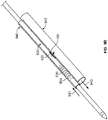
- FIG. 19 shows one variation of catheter (1900). Shown there are distal catheter body (1902), proximal catheter body (1904), and nesting material (1906) housing electrode (1908) and coupling magnets (1910).
- proximal (1904) and distal (1902) catheter bodies may be attached to the nesting material (1906) such that a circumference of at least a portion of the nesting material (1906) is not covered by a catheter body.
- the diameter of the nesting material (1906) and the electrode (1908) may be increased, which may allow the size of ablation surface of electrode (1908) to be increased without increasing the overall diameter of the catheter (1900)).
- an ablation surface may be at least partially recessed into a surface of the catheter.
- direct contact between an electrode surface and a blood vessel wall may yield carbon deposition on the surface during tissue ablation.
- a recessed ablation surface may help ablate tissue while minimizing carbon build-up on the ablation surface by providing spacing between the ablation surface and the blood vessel wall.
- blood or other fluid may be temporarily trapped within the recessed portion. The blood may provide an efficient conduction medium to help transfer the ablation energy to a blood vessel wall without carbon build-up on the ablation surface, which may help prevent or otherwise reduce degradation of the electrode.
- FIG. 5 shows a variation of catheter (500) comprising an electrode (502) with a recessed electrode ablation surface (504). Also shown there is nesting material (506) at least partially covering electrode (502). As noted above, nesting material (506) may help separate and insulate ablation surface (504) and electrode (502) from the remaining components of catheter (500). The size, shape, and depth of the aperture may be determined in part by the desired volume of blood that is to be held or otherwise trapped in the recessed portion of the catheter (500).
- each electrode may have one, two, three, or four or more ablation surfaces, and each ablation surface may have any suitable placement relative to the catheter body.
- an electrode may have a first ablation surface on a first side of the catheter and second ablation surface located distal or proximal to the first ablation surface along the first side of the catheter. Depending upon the spacing between the first and second ablation surfaces, this may contribute to the formation of two fistulas, or one enlarged fistula.
- the two or more ablation surfaces may be on different sides of the catheter, e.g., a first ablation surface may be on one portion of the catheter, and a second ablation surface may be located about 10°, about 20°, about 30°, about 45°, about 60°, about 90°, about 120°, about 150°, about 180°, about 200°, about 300°, etc. from the first ablation surface.
- the housed portion of the electrode may be housed inside of the nesting material.
- the housed portion of the electrode may have any suitable size or shape.
- electrode body (202) comprises a cylindrical portion (204) housed within the catheter body.
- the housed portion may be an elongate shape having a rectangular, triangular, elliptical, ovoid, polygonal or irregular cross-section.
- the housed portion of the electrode may be a semi-cylinder, a quarter-cylinder, or another suitable fractional portion of a cylinder. For example, FIG.
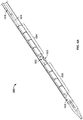
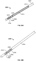
- FIG. 6A shows one such variation of catheter (600) comprising an electrode body (602) having an ablation surface (603), lead wire (605), proximal anchoring magnet (604), distal anchoring magnet (606), and lumen (608).
- the housed portion of electrode body (602) may be semi-cylindrical. Variations having a semi-cylindrical electrode body may allow for lumen (608) to pass thereby, as will be described in more detail.
- the electrode may have an aperture through it, such that a lumen of the catheter may pass therethrough.
- electrode body (310) is shown as having an aperture defined therein, such that lumen (308) may pass through the electrode body (310).
- an electrode may be positioned such that an ablation surface thereof may be substantially flush with or recessed within the catheter as the catheter is advanced through a blood vessel to the target site, and may subsequently be adjusted to protrude from the catheter body.
- the entire electrode body may be adjustable, while in other instances only a portion of the electrode is adjustable. Any suitable mechanism may be used to adjust the electrode, such as, for example, a spring mechanism.
- FIGS. 7A and 7B illustrate a variation of a catheter (700) comprising a movable electrode (702) and sleeve (704).
- electrode (702) may comprise a spring wire electrode, which may be movable between a retracted configuration, in which electrode (702) is retained within the catheter (as shown in FIG. 7A ), and a protruding configuration, in which electrode (702) projects from the surface of catheter (700) (as shown in FIG. 7B ).
- the electrode (702) may or may not be naturally biased to project from the catheter. When the electrode (702) is naturally biased to project from the catheter, such as in the variation shown in FIGS.
- a structure may be used to hold or maintain the electrode (702) in a retracted configuration.
- sleeve (704) may be used to control the protrusion of electrode (702).
- Sleeve (704) may be advanced distally to hold electrode (702) in a retracted configuration, as shown in FIG. 7A .
- Sleeve (704) may then be withdrawn proximally to expose electrode (702), which may then naturally move to a protruding configuration, as illustrated in FIG. 7B .
- Electrode (702) may protrude any suitable amount from the surface of the catheter (700) (e.g., between about 0.1 mm to about 1 mm, about 0.25 mm, about 0.5 mm, about 0.75 mm, about 1.0 mm, and the like).
- electrode While shown in FIGS. 7A and 7B as being naturally biased into a protruding configuration, electrode may be manually adjustable between a retracted configuration and a protruding configuration.
- FIG. 8 depicts one such variation of a catheter (800) with a leaf spring electrode (802) that may be actuated by wire (804).
- wire (804) may be slidably disposed within rod (806). Movement of wire (804) may transition electrode (802) between a retracted configuration and a protruding configuration.
- the amount of protrusion of the electrode (802) may be determined at least in part by the amount of movement of the wire (806), allowing for additional user control in deployment of the electrode.
- wire (804) may be attached to rod (806), and rod (806) may be movable within catheter (800) to advance or retract wire (804).
- the amount of protrusion of the electrode (802) may be determined at least in part by the amount of movement of the rod (806).
- FIG. 20 shows one such variation of a catheter (2000) comprising a deployable electrode (2002).
- catheter (2000) may comprise catheter body (2001), electrode (2002) and a distal coupling magnet array (2004).
- At least a portion of electrode (2002) may be covered/coated with an insulating material (2006), such that the uncovered portion (2008) of the electrode (2002) may act as an ablation surface.
- the insulated portion of the electrode (2002) may be coated in any suitable manner (e.g., plasma spraying, flame spring, dip coating, or the like), and insulating material (2006) may be any suitable material, such as one or more of the nesting materials described above.
- a rod, stiffened lead wire, or other actuation mechanisms may be used to move the electrode (2002) between a low-profile configuration (not shown), in which the electrode (2002) is housed within or flush with the catheter body (2001), and a deployed configuration, as shown in FIG. 20 .
- the actuation mechanism may compress the electrode (2002) such that it bends, flexes, or otherwise deforms away from the catheter body (2001). It should also be appreciated that in some instances, the electrode (2002) may naturally bend or flex away from catheter body (2001), and an actuation mechanism (or a sleeve) may be used to move the electrode (2002) to a low-profile configuration.
- FIG. 30 shows one such variation of a catheter (3000) comprising a deployable electrode (3002).
- catheter may comprise an electrode (3002) having a first electrode portion (3003) and a second patterned electrode portion (3004), catheter body (3006), and nesting material (3008) housing coupling magnets (3010) and having a track (3012).
- Electrode (3002) may be advanced from a retracted position, in which electrode (3002) is contained within track (3012) of nesting material (3008).
- first electrode portion (3003) may be configured to bend or flex away from the catheter body (3006), similar to electrode (2002) described above in relation to FIG. 20 .
- Second electrode portion (3004) may be attached to first electrode portion (3003), such that second electrode portion (3004) extends from catheter body (3006) when first electrode portion (3003) bends or flexes away from catheter body (3006).
- Second electrode portion (3004) may comprise one or more patterned surfaces, such as patterned surface (2902) of electrode (2900) described above with respect to FIGS. 29A and 29B .
- at least a portion of first electrode portion (3003) may be covered or otherwise coated with one or more insulating materials, such as one or more of the nesting materials described above. While shown in FIG. 30 as having two coupling magnets (3010) located distally from electrode (2900), it should be appreciated that catheter (3000) may comprise any alignment elements or combination of alignment elements, such as those described in more detail below.
- the catheter may additionally comprise a wire or other conductive structure which may electrically join the electrode to a current or ground source to carry current to or from the electrode.
- one or more portions of the wire or conductive structure may act as an electrode for ablating tissue.
- a wire may be disposed inside the catheter, outside the catheter, or a combination thereof.
- the wire may be embedded in the wall of the catheter, attached along an external surface of the catheter, and/or at least partially covered by a sheath or another non-conductive material (such as one or more nesting materials as described in more detail above).
- wire (104) may at least partially be located along the external surface of the catheter. As shown there, wire may further be shielded from surrounding tissue by sleeve (106).
- the wire may be at least partially disposed within the catheter.
- the wire may comprise a concentric electric conductor which may be disposed around one or more portions of the device.
- concentric electric conductor (314) may be connected to electrode (310).
- concentric electric conductor (314) may be disposed around a portion of lumen (308).
- Concentric electric conductor (314) may or may not be a braided material, and may be made of any suitable conductive material, such as copper, gold, platinum, and the like.
- the wire may be electrically insulated by a non-conductive material, such as parylene, ceramic, polytetrafluroethylene, polyetheretherketone, fluorinated ethylenepropylene, or the like. Electric insulation may serve a number of useful purposes. In some instances, the insulation may help prevent current loss from the wire. In other instances, the insulation may protect the wire from inadvertently contacting tissue or other components of the device. It should be appreciated that any of the catheters described here may comprise any electrode or combination of electrodes, any wire or conductive material, and/or any insulating or nesting materials as described above.
- the wire may be operatively connected to one or more generators for supplying RF energy to the electrode.
- the generator may supply any suitable current to the electrodes that is capable of ablating tissue.
- the generator may be configured to supply power between about 10 W and about 300 W.
- the generator may be configured to supply power between about 100 W and about 200 W.
- the generator may be configured to generate a pulsed current.
- the amplitude of the pulsed current may vary between pulses.
- the generator may be configured to generate an alternating current.
- one or more electrodes may be attached to the bipolar or monopolar outputs of the generator, as described in more detail above.
- the current may have any suitable frequency range, such as, for example about 300 kHz to about 9.5 MHz. It should also be appreciated that the generator may be configured to provide a plurality of power outputs. For example, in some variations a generator may be configured to supply a first output to fuse blood vessel tissue (as will be described in more detail below), and may be configured to supply a second output to ablate or vaporize tissue.
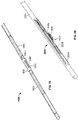
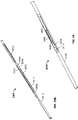
- FIGS. 21A and 21B show one such variation of catheter (2100).
- catheter (2100) comprises a distal catheter body (2102), proximal catheter body (2104), nesting material (2106) comprising coupling magnets (2108) and track (2110), and lead wire (2112).
- lead wire (2112) may be uncovered (e.g., not electrically isolated via one or more insulating coatings, nesting materials, or other non-conductive materials), such that the exposed portion of the lead wire (2112) may act as an ablation surface from which current may be delivered to ablate, vaporize or otherwise remove tissue.
- a distal portion of lead wire (2112) may be biased away from the catheter (2100), and may be moveable between three positions.
- the lead wire (2112) In a first position (not shown), the lead wire (2112) may be held or otherwise housed within the catheter (2100), which may allow for low-profile advancement of the catheter (2100) through the vasculature.
- the lead wire (2112) may then be advanced (or in some instances, withdrawn) such that the bias of the lead wire (2112) causes a distal portion of the lead wire (2112) to project out of catheter (2100) through track (2110), as shown in FIG. 21A .
- this bias may urge or otherwise press the lead wire (2112) against blood vessel tissue (not shown).
- a current may then be supplied to lead wire (2112) to ablate blood vessel tissue.
- the bias of the lead wire (2112) may continue to urge the distal portion of the lead wire (2112) through tissue, where it may come into contact with one or more portions of a second catheter (such as, for example, an electrode comprising a flat ablation surface such as those described above) in an adjoining blood vessel. Additionally, the lead wire (2112) may be further advanced (or withdrawn) during ablation to move the lead wire (2112) to a second position, as shown in FIG. 21B . As the lead wire (2112) is moved, it may move across blood vessel tissue to ablate a tract or path in the tissue, which may facilitate formation of the fistula. Following ablation, the lead wire (2112) may then be returned to its original low-profile configuration (or a different low-profile configuration), and the catheter may be repositioned or removed.
- a second catheter such as, for example, an electrode comprising a flat ablation surface such as those described above
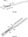
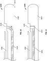
- FIGS. 31A and 31B illustrate another variation of catheter (3100).
- FIG. 31A shows a perspective view of catheter (3100), comprising catheter body (3102), nesting material (3104) with track (3106), coupling magnets (3108), and shaped lead wire (3110).
- FIG. 31B shows catheter (3100) with catheter body (3102) removed. Additionally shown in FIG. 31B are anchoring magnets (3112). Similar to the lead wire (2112) described above in relation to FIGS. 21A and 21B , at least a portion of lead wire (3110) may be uncovered and thus may act as an ablation surface to ablate or vaporize tissue. Additionally, the distal portion of lead wire (3110) may be configured to bias away from the catheter (3100), and may be moveable between three positions.
- the lead wire (3110) may be held or otherwise housed within the catheter (3100) (e.g., within nesting material (3104) and/or catheter body (3102)), which may allow for low-profile advancement of the catheter (3100) through the vasculature.
- the lead wire (3110) may then be withdrawn (or in some instances, advanced) such that the bias of the lead wire (3110) may cause the distal portion of lead wire (3110) to bias away from catheter body (3102), as shown in FIGS. 31A and 31B .
- lead wire (3110) may comprise a first segment (3114) housed at least partially within catheter body (3102), a first angled segment (3116) extending from a distal end of the first segment (3114), and a second angled segment (3118) extending from a distal end of the first angled segment (3116).
- First angled segment (3116) may extend from first segment (3114) at a first angle ( ⁇ 1 ), such that when lead wire (3110) biases away from catheter body (3102), first angled segment (3116) angles away from catheter body (3102) at first angle ( ⁇ 1 ).
- First angle ( ⁇ 1 ) may be any suitable angle (e.g., about 30 degrees, about 45 degrees, about 60 degrees, between about 30 degrees and about 60 degrees, between about 15 degrees and about 75 degrees, or the like).
- Second angled segment (3118) may be angled relative to first angled segment (3116) at a second angle ( ⁇ 2 ).
- Second angle ( ⁇ 2 ) may be any suitable angle (e.g., about 100 degrees, about 135 degrees, about 170 degrees, between about 100 degrees and about 170 degrees, or the like). In the variation shown in FIGS.
- lead wire (3110) may be configured such that when lead wire (3110) biases second angled portion (3118) is approximately parallel to the longitudinal axis of catheter body (3102), and separated from the catheter body (3102) by a distance (x).
- Distance (x) may be any value suitable to extend at least partially through vascular tissue during ablation (e.g., less than 1 mm, between about 1 mm and about 2 mm, between about 1 mm and about 3 mm, greater than about 4 mm, and the like).
- the first (3116) and second (3118) angled sections of the lead wire (3110) may be biased into tissue of the blood vessel.
- this bias may cause lead wire (3110) to press through or otherwise ablate blood vessel tissue.
- lead wire (3110) may come into contact with one or more portions of a second catheter (not shown) placed in an adjoining blood vessel, as will be described in more detail below.
- the lead wire (3110) may be further withdrawn (or advanced) during ablation to slide the lead wire (3110) relative to the catheter into a third position (not shown).
- the lead wire (3110) As the lead wire (3110) is moved, it may move across blood vessel tissue to ablate a tract or path in the tissue, which may facilitate formation of the fistula. Following ablation, the lead wire (3110) may then be returned to a low-profile (e.g., by withdrawing the lead wire (3110) relative to the catheter body (3102)), and the catheter may be repositioned or removed.
- a low-profile e.g., by withdrawing the lead wire (3110) relative to the catheter body (3102)
- One or more portions of lead wire (3110) may be coated over otherwise covered with one or more insulating materials.
- an insulating material (3122) may at least partially cover lead wire (3110). Insulating material may cover any suitable portion or portions of lead wire.
- an insulating material (3122) may cover first segment (3114) and first angled segment (3116), but not second angled segment (3118). In other variations, the insulating material (3122) may cover the first segment (3114) and only partially cover the first angled segment (3116), such that the second angled segment (3118) and a portion of the first angled segment (3116) remain uncovered.
- the second angled segment (3118) and uncovered portion of the first angled segment (3116) may act as an ablation surface.
- insulating material (3122) covers multiple segments of lead wire (3110), the same material may cover each segment, or different insulating materials may cover the different segments.
- Insulating material (3122) may comprise any suitable material or materials, such as those described above. In some variations, insulating material (3122) may comprise polyetheretherketone.
- FIG. 32 shows another variation of catheter (3200) comprising a lead wire (3202) having a first segment (3204), a first angled segment (3206), and a second angled segment (3208).
- catheter (3200) may comprise a catheter body (3210) having a recessed region (3212).
- catheter (3200) may comprise a lumen (3214) or other passageway extending through catheter body (3210).
- Lumen (3214) may extend through catheter body (3210) both proximally and distally of recessed region (3212), or may only extend through catheter body (3210) only proximally of recessed region (3212).
- lead wire (3202) may be uncovered, and lead wire (3202) may be moveable from a low-profile configuration and a biased configuration in which first angled segment (3206) angles away from first segment (3204) and catheter body (3210).
- first (3206) and second (3208) angled segments may be at least partially constrained within lumen (3214).
- at least a portion of first angled segment (3206) and/or second angled segment (3208) may be temporarily housed in a portion of lumen (3214) distally of recessed region (3212).
- lead wire (3202) may be withdrawn relative to catheter body (3210) to release first angled segment (3206) and second angled segment (3208) from lumen (3214), which may allow these segments to bias away from catheter body (3210) as described above.
- at least a portion of first angled segment (3206) and/or second angled segment (3208) may be temporarily housed in a portion of lumen (3214) proximally of recessed region (3212).
- the lead wire (3202) may be withdrawn to release first angled segment (3206) and second angled segment (3208) from lumen (3214).
- an insulating material (3216) may cover first segment (3204) and may partially cover first angled segment (3206), leaving second angled segment (3208) and a portion of first angled segment (3206) exposed.
- one or more insulating materials may also partially cover second angled segment (3208), but need not.
- the exposed portions of first (3206) and second (3208) angled segments may act as an ablation surface to ablate or vaporize tissue.
- Catheter body (3210) may also comprise one or more insulating nesting materials (not shown) or coatings which may help protect the catheter body (3210) from and in some instances redirect heat and energy produced by lead wire (3202) during ablation.
- the lead wire (3202) may be further withdrawn (or advanced) during ablation to slide the lead wire (3202) relative to the catheter. As the lead wire (3202) is moved, it may move across blood vessel tissue to ablate a tract or path in the tissue, which may facilitate formation of the fistula. Following ablation, the lead wire (3202) may then be returned to a low-profile, for example, by withdrawing the lead wire (3202) such that first angled segment (3206) and second angled segment (3208) are pulled into lumen (3214).
- one or more portions of an ablation surface of an electrode of a first catheter may extend or otherwise be advanced through blood vessel tissue during ablation.
- this advancement through blood vessel tissue may cause the ablation surface to contact one or more portions of the second catheter.
- the second catheter comprises an electrode having an exposed conductive surface
- direct contact between the electrodes of each catheter may cause the energy source (e.g., an electrosurgical generator) to shut off or otherwise cease tissue ablation.
- the energy source e.g., an electrosurgical generator
- contact between the electrode of the first catheter and the second catheter may damage one or more components of the second catheter.
- FIGS. 33A and 33B show one such variation of a catheter (3300).
- catheter (3300) may comprise a catheter body (3302), nesting material (3304) with pocket (3306), coupling magnets (3308), and electrodes (3310).
- FIG. 33B shows catheter (3300) with catheter body (3302) removed. Additionally shown there are anchoring magnets (3312).
- pocket (3306) may be configured to receive a portion of an electrode from a second catheter. For example, when catheter (3300) is placed within a blood vessel (not shown), and a second catheter is placed in an adjoining blood vessel, catheter (3300) may be positioned relative to the second catheter such that pocket (3306) may be aligned with an electrode (not shown) of the second catheter.
- Alignment may result from attraction between alignment elements of catheter (3300) (e.g., coupling magnets (3308) and/or anchoring magnets (3312) and corresponding alignment elements of the second catheter, as will be described in more detail below.
- the electrode of the second catheter may pass between the blood vessels, where it may be received by pocket (3306).
- Nesting material (3304) may be formed from or coated with an insulating material, such that energy delivered by the electrode does not damage catheter (3300) as electrode is received by pocket (3306).
- Pocket (3306) may be configured to receive any suitable electrode, as described in more detail above.
- pocket (3306) may be configured to receive a portion of a lead wire, such as wire (2112) of catheter (2100) describe above in relation to FIGS. 21A and 21B , lead wire (3110) of catheter (3100) described above with respect to FIGS. 31A and 31B , lead wire (3202) described above in relation to FIGS. 32A and 32B, or the like.
- the coupling magnets and anchoring magnets of catheters (3300) and (3100) may be configured such that when catheters (3300) and (3100) are placed in adjoining blood vessels, the pocket (3306) of catheter (3300) may be substantially aligned relative to track (3106).
- lead wire (3110) When lead wire (3110) is advanced (or withdrawn) such that a distal portion of the lead wire (3110) is biased out of track (3106), lead wire (3110) may be activated to ablate vessel tissue, as described in more detail below. As lead wire (3110) ablates through tissue, one or more portions of the lead wire (3110) (e.g., second angled portion (3118))) may enter or otherwise be received by the pocket (3306).
- catheter (3300) need not comprise any electrodes.
- electrodes (3310) may act as a passive ground electrode for an active electrode of a second catheter (e.g., lead wire (3110) of catheter (3100) described above) or vice versa, which may aid in tissue ablation.
- FIGS. 33A and 33B as having two electrodes (3310), it should be appreciated that the catheters described here may comprise any suitable number of electrodes (e.g., zero, one, two, or three or more electrodes).
- FIG. 34 illustrates one such variation of a catheter (3400) comprising a single electrode (3402).
- Pocket (3408) may be configured to receive one or more portions of an electrode of a second catheter, as described in more detail above. While electrode (3402) is proximal to pocket (3408) in the variation of catheter (3400) shown in FIG. 34 , in other variations electrode (3402) may be positioned distal to pocket (3408).
- a catheter may comprise a pocket formed in an electrode.
- FIGS. 35A and 35B show one such variation of catheter (3500).
- catheter may comprise a catheter body (3501) and nesting material (3502).
- Nesting material (3502) may house electrode (3504) and coupling magnets (3506) therein.
- FIG. 35B shows catheter (3500) with catheter body (3501) removed, and further shows anchoring magnets (3510).
- Pocket (3508) may be formed in electrode (3504), and may be configured to receive a portion of an electrode from a second catheter.
- pocket (3508) may be electrically and/or thermally insulated by depositing one or more insulating coatings (e.g., a refractory metal oxide coating) onto the surfaces of pocket (3508), which may allow pocket (3508) to receive and contact at least a portion of an electrode without pocket (3508) providing a direct electrical connection.
- pocket (3508) may be configured to allow for electrical conduction therethrough without direct physical contact with an external electrode.
- pocket (3508) may be covered or otherwise coated with a porous insulating coating (e.g., a porous metal oxide coating).
- the porous coating may allow for electrical conduction through the pocket (3508) without direct electrode-to-electrode physical pocket, which may prevent short-circuiting or interruption of ablation.
- catheters described here need not comprise a pocket. Indeed, in some variations one or more portions of the device may be electrically insulated or partially electrically insulated to allow for direct contact with one or more electrodes of a second catheter.
- FIG. 36 illustrates one such variation of catheter (3600).
- catheter (3600) may comprise a catheter body (3602) and a nesting material (3604).
- Nesting material (3604) may house an electrode (3606) and coupling magnets (3608) therein.
- Electrode (3606) may further comprise one or more coated segments (3610).
- Coated segment (3610) may comprise an insulating coating (as described in more detail above) or a partially-insulating coating (e.g., a porous coating as described immediately above).
- Catheter (3600) may interact with a second catheter (not shown), such that when the catheters are placed in adjoining blood vessels, an electrode of the second catheter may extend through vessel tissue during ablation and contact coated segment (3610) without damaging or short-circuiting the device. While the coated segment (3610) of electrode (3606) shown in FIG. 36 may be recessed relative to the remainder of the electrode, it should also be appreciated that in some variations the coated segment (3610) may be flush relative to the uncoated portions of the electrode (3606)
- a catheter may comprise one or more mechanical cutting elements.
- a catheter may comprise a blade that may be advanced or otherwise extended from the catheter to cut or otherwise sever tissue.
- FIG. 22 shows one such variation of catheter (2200) comprising a nesting material (2201) comprising track (2202) and a blade (2204).
- Blade (2204) may have any suitable shape and configuration (e.g., single-edge, double-edge, pointed, rounded, or the like). Blade (2204) may be rotatably, translatably, or otherwise coupled to catheter (2200) such that it may be deployed through track (2202) to cut or otherwise sever tissue.
- the blade (2204) may be configured to oscillate relative to catheter (2200) to cut or otherwise sever tissue.
- Blade (2204) may be deployed by any suitable mechanism (e.g., one or more mechanical actuators, magnet-based actuators, electronic actuators, or the like), and may be withdrawn into track (2202) to allow for low-profile advancement or withdrawal of the catheter.
- the blade (2204) may be used to pierce or puncture one or more balloons in a corresponding catheter in another blood vessel.
- the blade (2204) may electrically connected to an electrosurgical generator such that blade (2204) may act as an electrode, like those electrodes described in more detail above.
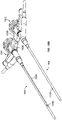
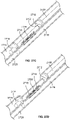
- FIGS. 37A and 37B show cross-sectional perspective views of a variation of catheter (3700), and illustrate a mechanism by which a blade (3702) may be advanced out of catheter (3700).
- Catheter (3700) may comprise a recess (3704) in catheter body (3705).
- Blade (3702) may be moveable from a low-profile configuration, in which blade (3702) is housed in recess (3704) (as shown in FIG. 37A ) to a cutting configuration, in which blade (3702) is advanced out of recess (3704) (as shown in FIG. 37B ).
- Catheter (3700) may comprise a rotation arm (3706) and an activation wire (3708), which may help move blade (3702) between the retracted and cutting configurations, as will be described in more detail below. Also shown in FIGS. 37A and 37B are coupling magnets (3710) located proximal and distal of blade (3702), although it should be appreciated that catheter (3700) need not comprise any alignment element or may comprise any suitable alignment elements or combinations of alignment elements as described in more detail below.
- rotation arm (3706) may be pivotally connected to blade (3702) at a first pivot point (3712) at or near a first end of rotation arm (3706), and may also be pivotally connected to the catheter body (3705) at a second pivot point (3714) at or near a second end of rotation arm (3706).
- the pivot points described here may comprise one or more pins, projections, other structures that allow for rotational movement between two members.
- second pivot point (3714) may comprise a pin (3716).
- the second pivot point (3714) may additionally be configured to move along the longitudinal axis of the catheter body (3705).
- pin (3716) of second pivot point (3714) may be slidably disposed in a track (3718) within catheter body (3705), such that pin (3716) may both rotate and slide relative to track (3718) and catheter body (3705).
- Blade (3702) may further be pivotally connected to the catheter body (3705) at a third pivot point (3720).
- activation wire (3708) may be connected to rotation arm (3706) at or near its second end.
- activation wire (3708) may be attached to a portion of pin (3716).
- Activation wire (3708) may be manipulated to move blade (3702) between a retracted position (as shown in FIG. 37A ) and an extended cutting position (as shown in FIG. 37B ).
- Activation wire (3708) may be pulled proximally relative to the longitudinal axis of the catheter (3702), which may cause second pivot point (3714) to slide proximally relative to the catheter body.
- second pivot point (3714) moves proximally toward third pivot point (3720)
- the rotation arm (3706) and blade (3702) may each rotate away from catheter body (3705), as shown in FIG. 37B .
- catheter (3700) When catheter (3700) is placed in a blood vessel, rotation of blade (3702) into a cutting position may cause blade (3702) to cut or otherwise sever vessel tissue.
- the activation wire (3708) may be advanced distally relative to the catheter (3700), which may move second pivot point (3714) away third pivot point (3720), which may cause rotation arm (3706) and blade (3702) to rotate back toward the catheter body.
- catheter (3700) may be configured such that distal advancement of the activation wire causes rotation arm (3706) and blade (3702) to rotate blade to an extended position, while proximal withdrawal of the activation wire causes rotation arm (3706) and blade (3702) to rotate blade (3702) to a retracted position.
- FIGS. 38A and 38B depict another variation of a catheter (3800) comprising a blade (3802).
- catheter (3800) may comprise a catheter body (3804), and a recess (3806) in catheter body (3804) through which blade (3802) may extend.
- guide plates (3810) on both sides of recess (3806), and activation wire (3814).
- FIG. 38B shows a cross-sectional side view taken along the longitudinal axis of catheter (3800).
- blade (3802) may be pivotally attached to one or more of guide plates (3810) at pivot point (3812).
- the pivot point (3812) may comprise one or more pins or projections, as described immediately above.
- a distal portion of activation wire (3814) may be attached to blade (3802), and may extend through a lumen (3816) or other passageway in the catheter body (3804).
- a proximal portion of activation wire (3814) may be manipulated to withdraw or advance activation wire (3814) within lumen (3816), and this movement may cause blade (3802) to rotate relative to pivot point (3812).
- withdrawal of the activation wire (3814) may cause the blade (3802) to rotate outwardly from catheter body (3804) (as shown in FIG. 38A ), while advancement of activation wire (3814) may cause blade (3802) to rotate to a retracted position (such as shown in FIG. 38B ).
- catheter (3800) When catheter (3800) is advanced into a blood vessel (not shown), the catheter (3800) may be advanced with blade (3802) in a retracted position within the catheter body (3804).
- a user When catheter (3800) is positioned within the blood vessel, a user may withdraw or otherwise retract pull wire to rotate the blade (3802) to an extended position, whereby blade (3802) may cut or otherwise sever tissue.
- blade (3802) When blade (3802) is in an extended position, catheter may optionally be moved relative to the blood vessel to further cut or otherwise sever tissue.
- pivot point (3812) may be moveable relative to the catheter body (3804), such that pivot point (3812) and blade (3802) may be translated along the longitudinal axis of the catheter body (3804).
- the activation wire (3814) may be advanced to return blade (3802) to a retracted position.
- Catheter (3800) may optionally be repositioned and reactivated to cut or sever tissue at another location, or catheter (3800) may be removed from the blood vessel. While catheter (3800) is illustrated above as being configured such that withdrawal of activation wire (3814) extends blade (3802) from catheter body (3804) and advancement retracts blade (3802) into catheter body (3804), it should be appreciated that catheter (3800) may be configured such that advancement of activation wire (3814) may extend blade (3802) from catheter body (3804) and withdrawal of the activation wire (3814) may retract blade (3802) into the catheter body (3804).
- FIGS. 39A-39C illustrate yet another variation of a catheter (3900) comprising a blade (3902).
- FIG. 39A shows a perspective view of a portion of catheter (3900) with blade (3902) in an extended position, extending from a recess (3904) in catheter body (3906).
- FIGS. 39B and 39C show cross-sectional side views of catheter (3900) along its longitudinal axis.
- blade (3902) may be attached to a first wire portion (3908) and a second wire portion (3910).
- First wire portion may be attached to or otherwise engage a translation wire (3912) at connection point (3914).
- first wire portion (3908) and second wire portion (3910) may comprise a shape-memory material, and may be configured such that first wire portion (3908) and second wire portion (3910) bias blade (3902) away from translation wire (3912) and toward an extended position, as shown in FIG. 39C .
- second wire portion (3910) may be pulled away from connection point (3914) in the direction of arrow (3916). This may cause first (3908) and second (3910) wire portions to at least partially straighten, which may withdraw blade (3902) into catheter body (3906).
- Second wire portion (3910) may be locked or otherwise fixed relative to translation wire (3912) to hold blade (3902) in a retracted position.
- catheter (3900) may be advanced into a blood vessel (not shown) with blade (3902) in a retracted position. Once positioned (e.g., using one or more alignment elements, visualization methods, or the like), blade (3902) may be moved to an extended position. To do this, second wire portion (3910) may be unlocked relative to translation wire (3912), which may allow first (3908) and second (3910) wire portions to return to their outwardly biased positions, thereby extending blade (3902) to an extended position, as shown in FIG. 39C . In some variations, a user may advance or otherwise move second wire portion (3910) toward connection point (3914) to help bias blade (3902) in an extended position.
- second wire portion (3910) may be locked or otherwise fixed relative to translation wire (3912) to hold blade (3902) in an extended position.
- translation wire (3912) Once extended from catheter body (3906), translation wire (3912) may be advanced or withdrawn relative to catheter body (3906) to translate blade (3902) along the longitudinal axis of the catheter, which may allow blade (3902) to cut a larger tract of tissue.
- catheter (3900) may be advanced or withdrawn relative to the blood vessel with blade (3902) extended to cut a larger tract of tissue.
- the second wire portion (3910) may then be withdrawn relative to translation wire (3912) and connection point (3914) to return blade (3902) to a retracted position, and the catheter (3900) may be repositioned or removed.
- catheters comprising blades may include any of the additional device features described hereinthroughout.
- the catheters may comprise one or more alignment elements.
- the catheters may comprise one or more anchoring magnets and/or one or more coupling magnets.
- the catheter may comprise one or more shape-changing elements and/or one or more markers, as will be described in more detail below.
- the catheters described here may be configured to deliver laser energy to tissue to vaporize or otherwise remove tissue during fistula formation.
- these catheters may comprise an optical fiber which may run from a proximal portion of the catheter to a distal portion of the catheter.
- a proximal portion of the optical fiber may operatively connected (e.g., via a SMA connector, or the like) to a laser generator.
- Laser energy produced by the laser generator may propagate or otherwise pass through the optical fiber, and may be delivered from optical fiber to tissue to vaporize tissue.
- the catheter may comprise one or more lenses, mirrors, diffuser, and/or other components which may redirect light from the optical fiber toward tissue.
- the laser generator may be configured to produce any suitable laser energy. In some variations, it may be desirable to produce light energy having a wavelength with high water absorption, which may promote energy absorption by vessel tissue. In some variations, the laser generator may be configured to generate infrared energy. Examples of suitable wavelengths include, but are not limited to, about 730 nanometers, between about 680 nanometers and about 780 nanometers, about 820 nanometers, between about 750 nanometers and about 870 nanometers, about 930 nanometers, between about 880 nanometers and about 980 nanometers, about 970 nanometers, between about 920 nanometers and about 1020 nanometers, about 1200 nanometers, between about 1150 nanometers and about 1250 nanometers, about 1450 nanometers, between about 1400 nanometers and about 1500 nanometers, about 1950 nanometers, between about 1900 nanometers and about 2000 nanometers, about 2900 nanometers, between about 2850 nanometers and about 2950 nanometers or the like. Examples of suitable
- FIG. 43 shows a distal portion of one variation of catheter (4300) which may be configured to deliver laser energy to tissue.
- catheter (4300) may comprise catheter body (4302), optical fiber (4304), and irrigation lumen (4306).
- optical fiber (4304) may run along the longitudinal axis (4310) of catheter body (4302), and a distal portion of the optical fiber (4304) may bend to direct the distal end of the optical fiber (4304) out of a side of the catheter body (4302).
- the distal portion of the optical fiber (4304) may bend at any angle ( ⁇ ) relative to the longitudinal axis (4310) of the catheter body (4302). In some variations, angle ( ⁇ ) may be about 45 degrees. In other variations, angle ( ⁇ ) may be about 90 degrees. In still other variations, angle ( ⁇ ) may be between about 45 degrees and about 90 degrees. In yet other variations, angle ( ⁇ ) may be less than about 45 degrees, or greater than about 90 degrees.
- laser energy may be passed through optical fiber (4304) and out the side of catheter body (4302), where it may vaporize, ablate, or otherwise remove tissue.
- a gas e.g., carbon dioxide
- fluid e.g., saline
- one or more fluids may be passed through catheter body (4302) via irrigation lumen (4306) and be delivered between the optical fiber (4304) and tissue (not shown).
- the gas or fluid may be introduced continuously or intermittently during tissue vaporization, and may help to minimize or otherwise prevent excessive heating or damage to surrounding tissue.
- the catheter may comprise a space (4308) between the end of the optical fiber (3404) and the side wall of the catheter body (4302). Space (4308) may separate the end of the optical fiber (3404) from the side wall of the catheter body (4302) by any suitable amount (e.g., about 0.5 mm, about 1 mm, about 1.5 mm, between about 0.5 mm and about 1.5 mm, greater than about 1.5 mm, and the like). Additionally, in variations where an irrigation lumen (4306) is used to deliver a gas or fluid between the output of the optical fiber (4304) and tissue, gas or fluid may be delivered into or through space (4308).
- a catheter may comprise one or more lenses, diffusers, mirrors, or the like, for altering or otherwise redirecting light passing through an optical fiber.
- FIG. 44 shows one variation of a catheter (4400) comprising a diffuser (4410) which may redirect laser energy provided through an optical fiber (4404).
- catheter (4400) may comprise a catheter body (4402), an irrigation lumen (4406), optical fiber (4404), and diffuser (4410).
- Diffuser (4410) may be attached at or near the distal end of the optical fiber (4404), and may redirect light from optical fiber (4404) out of the side of catheter body (4402).
- a space (4408) within catheter body (4402) may separate an output of diffuser (4410) from tissue.
- irrigation lumen (4406) may be positioned to pass fluid between diffuser (4410) and tissue (not shown), as described immediately above.
- the catheters described here may comprise one or more alignment elements to help align or otherwise reposition the catheters when placed in the vasculature.
- alignment elements may help bring two or more catheters (and with them, two or more blood vessels) in closer approximation.
- the alignment elements may help ensure that one or more catheters are in proper axial or rotational alignment relative to another catheter (or catheters). Ensuring proper position of catheters and blood vessels may help facilitate formation of a fistula with one or more of the fistula-forming elements described above.
- catheters may comprise mechanical alignment features, such as protrusions, grooves, flat surfaces, and the like, that may or may not interact with one or more alignment features on another catheter.
- a catheter may have one or more magnetic components that may interact with one or more magnetic components of another catheter or one or more magnets positioned externally from the body.
- the catheter may comprise one or more markers that may help a user to align one or more catheters.
- a catheter may comprise one or more shape-changing members for adjusting the positioning of a catheter. It should be appreciated that each catheters described here may comprise any alignment element or combination of alignment elements described below, and in variations where the catheter comprises a fistula-forming element, may comprise any fistula forming element or combination of elements described in more detail above.
- a catheter may comprise one or more magnetic alignment components. These magnetic alignment components may be attracted to one or more additional elements (e.g., one or more portions of a second catheter, one or more magnets or other components placed externally from the body) to help position or align the catheter within a vessel. For example, one or more magnets placed outside of the body may interact with the magnetic alignment components of a catheter to help facilitate advancement of the catheter through the vasculature, as will be described in more detail below.
- a catheter may comprise one or more "anchoring" magnetic alignment elements that act to attract the catheter toward one or more portions of a second catheter, thereby bringing the catheters in closer approximation.
- a catheter may comprise one or more "coupling" magnetic alignment elements, which may act to rotationally (and/or axially) orient and/or mate a surface of the catheter with one or more surfaces or portions of a second catheter.
- a catheter may comprise any number of individual magnets (e.g., zero, one, two, three, four, five, six, seven, or eight or more, etc.).
- Each magnetic component may be any suitable magnet or magnetic material.
- a catheter may comprise one or more rare-earth magnets (e.g., neodymium magnets or samarium-cobalt magnets) and/or one or more selectively-activated electromagnets.
- these magnets may be grouped into one or more arrays. These magnetic arrays may located inside or outside of a catheter (or a combination thereof), and may be positioned anywhere along the length of the catheter.
- each magnet or magnet array may be configured or arranged to align with one or more magnets or magnet arrays from a second catheter.
- Each magnet may be fixed in or on a catheter by any suitable method.
- one or more magnets may be embedded in, adhered to or friction fit within a catheter.
- Each magnet may have any suitable diameter (e.g., about 0.075 in., about 0.080 in., about 0.029 inch, about 0.110 inch, or the like) or length (e.g., about 5 mm, about 10 mm, about 15 mm, about 20 mm, or the like), and may be separated from adjoining magnets by any suitable distance (e.g., about 1 mm, about 5 mm, and the like).
- the magnets of an array may have alternating polarity (e.g., each magnet will have the opposite polarity as any adjacent magnets), matching polarity, or combinations thereof.
- one or more portions of the catheter may be made from a magnetic material, and/or may be embedded with one or more magnetic particles/materials.
- Each magnet may have any suitable shape for placement inside or outside of the catheter. Magnets may be cylindrical, semi-cylindrical, tube-shaped, box-shaped, or the like.
- catheter (200) may comprise a proximal anchoring magnet array (206) and a distal anchoring magnet array (208), the magnets of each of which are cylindrical.
- catheter (600) may comprise a proximal anchoring magnet array (604) and a distal anchoring magnet array (606), the magnets of each of which are semi-cylindrical.
- a lumen and/or lead wire may pass by or along the anchoring magnet arrays, because the semi-cylindrical magnets only take up a portion of the interior of catheter (600).
- FIG. 6A shows another variation of catheter (610) comprising electrode body (612) having ablation surface (613), proximal anchoring magnet array (614), distal anchoring magnet array (616), lead wire (615) and lumen (618).
- the apex of each magnet of the proximal (614) and distal (616) anchoring magnet arrays may be perpendicular to ablation surface (613).
- each individual magnet or anchoring magnet array may have any rotational positioning relative to ablation surface (613), which may or may not be the same as the rotational position as another magnet or array of magnets.
- one or more magnets may have one or more lumens or passageways therethrough, which may allow one or more other components (e.g., a lead wire, actuation mechanism, lumen, combinations thereof and the like) of catheter to pass through the magnets.
- catheter (300) comprises proximal and distal anchoring magnet arrays ((302) and (304) respectively) having tube-shaped magnets.
- concentric electrical conductor (314) may pass through the magnets of proximal anchoring magnet array (302), and lumen (308) may pass through the magnets of the proximal and distal anchoring magnet arrays ((302) and (304) respectively).
- one or more magnetic alignment components may comprise one or more box-shaped magnets (e.g., a magnet with a substantially rectangular cross-section).
- FIG. 23 shows one such variation of catheter (2300). Shown there is tip (2302), distal anchoring magnet array (2304), proximal anchoring magnet array (2306), and nesting material (2308) comprising coupling magnets (2310), electrode body (not shown) with ablation surface (2312) and marker (2316).
- Catheter (2300) further comprises a catheter body (or a plurality of catheter segments, such as those described above), but the catheter body is not illustrated in FIG. 23 so as to highlight the internal components of catheter (2300). Additionally, while shown in FIG. 23 as comprising coupling magnets (2310) and marker (2316) (each of which will be described in more detail below), catheter (2300) need not.
- distal anchoring magnet array (2304) comprises a cylindrical anchoring magnet (2316) and a box-shaped anchoring magnet (2314), while proximal anchoring magnet array (2306) comprises a box-shaped anchoring magnet (2314).
- the anchoring magnet arrays may have any suitable combination of magnets, such as one or more of the magnets described above.
- the box-shaped magnets may help bring the catheter in closer approximation with a second catheter, but may also help rotationally orient the catheter relative to the second catheter.
- the attractive strength between the two magnets may be greatest when the magnets are aligned.
- a front surface (2320) of box-shaped magnet (2314) may align with a front surface of another box-shaped magnet (not shown) of a catheter in another blood vessel.
- the attractive force between the magnets may be greatest when the front surfaces are aligned with each other, and thus the magnets may naturally rotate or facilitate rotation to the aligned position.
- the nesting material may house one or more coupling magnets for temporarily magnetically coupling a surface or portion of the nesting material to one or more portions of another catheter or device.
- the coupling magnets may be configured such that the attractive force between two catheters is greatest when a surface of each catheter is aligned with the other.
- nesting material in the variation of catheter (2300) shown in FIG. 23 above, nesting material (2308) comprises coupling magnets (2310).
- the longitudinal axis of the coupling magnets (2310) may be substantially transverse to the longitudinal axis of the catheter.
- coupling magnets (2310) may have a flat mating surface which may attract a flat mating surface of a coupling magnet of another catheter (not shown). As described in more detail above in regards to flat ablation surfaces, the flat mating surfaces of a coupling magnet may act to flatten tissue between two catheters, which may aid in ablation by the ablation surface.
- FIG. 24A shows a first variation of catheter (2400). Shown there is catheter body (2402) and nesting material (2406) housing an electrode (2408) and a distal coupling magnet array (2412), wherein the electrode (2408) comprises ablation surface (2410). While shown in FIG.
- distal coupling magnet array (2412) may comprise any suitable number of coupling magnets (2414) (e.g., one, two, or three or more).
- a nesting material may comprise a plurality of coupling magnet arrays.
- FIG. 24B shows a variation of catheter (2416) comprising catheter body (2418), nesting material (2420) housing electrode (2422) with ablation surface (2424), proximal coupling magnet array (2426) and distal coupling magnet array (2428).
- Each of the coupling magnet arrays may comprise any suitable number of coupling magnets (2430), as mentioned immediately above.
- the catheter may be configured that a fistula-forming element may be placed in close proximity to the distal end of the catheter body.
- a fistula-forming element may be placed in close proximity to the distal end of the catheter body.
- the electromagnets may be independently activated or may be activated as a group.
- electromagnets of a magnet array may be activated one at a time to help ensure a certain alignment orientation with respect to another magnetic device, e.g., proximal magnets may be activated prior to activating distal magnets, every other magnet may be activated in sequence, etc.
- two or more magnets may be activated simultaneously to promote secure attachment to another magnetic device.
- the catheter may comprise one or more shape-changing elements for approximating two or more blood vessels.
- the shape-changing element may have a first configuration during advancement of the catheter through the vasculature. Once the catheter reaches a target location, the shape-changing element may be altered to a second configuration, which may alter the overall shape of the catheter. As the catheter changes shape, the catheter may move or reconfigure one or more portions of the blood vessel, which may help bring that portion or portions of the blood vessel in closer approximation to one or more portions of a second blood vessel.
- the shape of a catheter may be altered in any suitable manner.
- a catheter may comprise one or more pull wires, which may pulled or push to deflect or otherwise alter the shape of the catheter.
- a catheter may comprise one or more shaped wires which may alter the shape of the catheter, as will be described in more detail below.
- FIGS. 25A-25D illustrate one variation of catheter (2500).
- FIG. 25A shows a partial cross-sectional area of catheter (2500). Shown there is catheter body (2502), nesting material (2504) housing coupling magnets (2508) and an electrode body (not shown) comprising ablation surface (2506), shaped lead wire (2510), straightening cannula (2512), and torque-transmitting sheath (2514). A portion of catheter body (2502) is not shown in FIG. 25A to help illustrate the other elements of catheter (2500). While shown in FIG. 25A as having an electrode housed within nesting material (2504) to define ablation surface (2506), catheter (2500) may comprise any suitable fistula-forming element, such as those described in more detail above.
- catheter (2500) need not.
- the catheter may comprise any magnets or combination of magnets, such as those described above.
- catheter (2500) may or may not comprise a torque-transmitting sheath (2514), which may help rotate the catheter, as will be described in more detail below.
- Shaped lead wire (2510) may be used to alter the shape of catheter (2500). Specifically, shaped lead wire (2510) may be pre-formed with one or more bends or curves. A straightening cannula (2512) may be advanced over lead wire (2510) to temporarily straighten or otherwise constrain the bends and curves of the shaped lead wire (2510), thereby rendering the distal portion of the catheter (2500) substantially straight, as shown in FIG. 25B .
- Catheter (2500) may be advanced into a blood vessel (not shown), at which point the straightening cannula (2512) may be withdrawn. Once withdrawn, shaped lead wire (2510) may return to its original configuration, which may cause catheter (2500) to change shape, as shown in FIG. 25C .
- FIG. 25D shows one variation in which two catheters (2518) and (2520) are placed in adjoining blood vessels (2522).
- catheters (2518) and (2520) may comprise the components of catheter (2500) described immediately above.
- the lead wires of each catheter may take on a bent/curved configuration, which may cause the distal portions of each of catheters to bend or flex toward each other, thereby bringing a portion of the blood vessels (2522) closer together as shown in FIG. 25D .
- One or more fistula-forming elements may then be activated to form a fistula between the adjoining blood vessels (2522).
- Shaped lead wire may act as a lead wire to carry current to or from an electrode, but need not.
- a device may comprise a shaped wire and a separate lead wire.
- the catheter may comprise a shaped wire but no lead wire.
- a shaped member may be located outside of catheter.
- the shaped member may be at least partially covered by one or more sheaths or other coverings, such as those described above. It should also be appreciated that any suitable shaped structure may be used to alter the shape of the catheters described here.
- a catheter comprises one or more expandable structures (e.g., a balloon or the like), as will be described in more detail below, the expandable structure may be used in conjunction with a shape-changing member to help position a catheter within a vessel.
- catheter (2500) may further comprise one or more expandable structures (not shown), such as one or more inflatable balloons. These expandable structures may be expanded inside of a blood vessel to temporarily hold catheter (2500) in place relative to the vessel.
- catheter (2500) may comprise a single expandable structure, which may be located proximal or distal to the bend of the shaped lead wire (2510). In other variations, catheter (2500) may comprise one or more expandable structures on either side of the bend of the shaped lead wire (2510). In variations where a shaped lead wire comprises multiple bends, expandable structures may be positioned proximal and/or distal all, some, or none of the bends.
- the expandable structures may be used in conjunction with any suitable shape-changing element (e.g., a shaped wire, a pull wire, or the like), and may be used to provide temporary attachment and/or fixation between the catheter body and vessel tissue in any suitable manner.
- any suitable shape-changing element e.g., a shaped wire, a pull wire, or the like
- the catheters described here may comprise one or more markers that may allow for visualization of one or more portions of a catheter during positioning and/or orientation thereof.
- the marker may be directly visualized.
- the marker may be indirectly visualized (e.g., via ultrasound, fluoroscopy and/or X-ray visualization).
- Markers may be located anywhere relative to the catheter, e.g., one or more surfaces of the catheter, inside of the catheter.
- one or more portions of the catheter may be made from an echogenic or radiographic material.
- a marker may be attached to the catheter by any suitable method, for example, by mechanical attachment (e.g., embedded in a portion of the catheter, circumferential circumscription, or the like), adhesive bonding, welding, soldering, combinations thereof or the like.
- FIGS. 14A-14D illustrate one variation of catheter (1400) comprising marker bands (1402). Also shown in FIG. 14A are anchoring magnets (1410), and electrode (1404) partially covered by nesting material (1406) and comprising ablation surface (1408).
- Catheter (1400) may comprise any suitable number of marker bands (1402), and each marker band (1402) may be positioned at any suitable location in or on catheter (1400).
- Marker bands (1402) may comprise cut-out regions that may help a practitioner determine the position of a catheter via one or more imaging techniques.
- FIG. 14B shows a perspective view of one marker band (1402) comprising a first cut-out region (1412) and a second cut-out region (1414).
- First (1412) and second (1414) cut-out regions are shown in FIGS. 14B-14D as having the same shape, but need not.
- marker band (1402) When marker band (1402) is visualized (e.g., via ultrasound or fluoroscopy), a user may be able to see the negative space formed by the overlapping segment (1416) of first (1412) and second (1414) cut-out regions.
- the shape of this overlapping segment (1416) may change as catheter (1400) (and with it, marker band (1402)) is rotated. Eventually, rotation of marker band (1402) may reach a point where first (1412) and second (1414) cut-out regions completely or substantially overlap, as shown in FIG. 14D .
- marker band (1402) When marker band (1402) reaches this "aligned" configuration (or when two markers on associated catheters are each in an “aligned” configuration), a user may know that the catheter is in a rotational orientation suitable for activating a fistula-forming element.
- the ablation surface (1408) may be positioned relative to marker bands (1402) such that the ablation surface (1408) faces a direction perpendicular to the cut-out regions.
- the marker bands of each catheters may be used to rotationally and/or axially position the catheters such that that one or more fistula forming elements are properly positioned to form a fistula.
- the cut-out regions may be any shapes or combination of shapes, e.g., rectangular, circular, elliptical, multi-lobular shapes, alphanumeric symbols, any shape with one or more axes of symmetry (e.g., bilateral symmetry), and the like.
- the cut-out regions may have a directional shape, which may have a tapered portion that indicates the location of the ablation surface of an electrode, e.g., a polygon with a vertex at an acute angle, arrow, and the like.
- First and second cut-out regions may have the same shape as each other, or may each have different shapes.
- Other orientation markers or indicators may be provided on the catheter and/or electrode as desired and described below. While shown in FIGS. 14A-14D as comprising marker bands, it should be appreciated that the catheters described here may comprise any marker that is capable of indirect visualization.
- the catheter may comprise one or more visual markers that may help align two or more catheters relative to each other.
- FIGS. 15A and 15B illustrate one variation of catheter (1500) comprising a lateral stripe (1504) which may help orient catheter (1500).
- lateral stripe (1504) may be a visual marker with a known location relative to a fistula-forming element (1508).
- lateral stripe (1504) is longitudinally aligned with fistula-forming element (1508).
- the lateral stripe (1504) (which may at least partially remain outside of the body) may give a visual indication as to the rotational orientation of the fistula-forming element (1508).
- the relative positioning of laterals stripes (1504) may give an indication of the relative positioning of the two catheters.
- the fistula-forming elements (1508) of each catheter (1500) may be in an appropriate orientation for activation of the fistula-forming elements.
- Lateral stripe (1504) may be applied to catheter (1500) in any suitable manner (e.g., via ink marking, texturing, application of one or more colored adhesives, etc.).
- a catheter may comprise one or more balloons or other expandable structures. These expandable structures may serve one or more functions.
- an expandable structure may help appose an electrode surface (or other fistula-forming element) against one or more vessel walls. This apposition may help temporarily flatten or otherwise relocate tissue, and may act to displace blood from the area. Additionally, during fistula formation, the expandable member may continue to urge the fistula forming element against tissue as it is removed from the vessel wall.
- the expandable structure may be configured to help provide apposition between the catheter and a vessel wall, while still allowing for blood flow through the blood vessel.
- one or more expandable structures may help modify or otherwise alter the size or shape of a fistula.
- the expandable structures may be used to dilate, contract, or otherwise displace a portion of one or more blood vessels. In some of these variations, this displacement may help bring a portion of the blood vessel closer to a skin surface.
- one or more expandable structures may be used to hold a catheter in place relative to a blood vessel, and may aid in repositioning the blood vessel.
- the catheter may comprise one or more balloons.
- FIGS. 9A-9D depict various illustrations of catheters comprising a balloon.
- the balloon may be configured to push a portion of a catheter (e.g., an ablation surface or other fistula forming element) into contact with a blood vessel wall.
- FIG. 9A depicts one variation of catheter (900) comprising balloon (902), and an electrode body (not shown) having an exposed ablation surface (904).
- Balloon (902) may have an undeployed collapsed configuration (not shown) for low-profile advancement and a deployed expanded configuration (as shown in FIG. 9A ). In the variation shown in FIG.
- balloon (902) may be non-concentrically mounted on the catheter (900) away from ablation surface (904) such that expansion of balloon (902) within a blood vessel may bias, press, or otherwise push ablation surface (904) against a blood vessel wall.
- expansion of the balloon (902) may help flatten tissue against the ablation surface.
- the balloon (902) may aid in fistula formation by continuing to urge the ablation surface (904) against and through the blood vessel wall as tissue is ablated, vaporized or otherwise removed.
- expansion of the balloon (902) may help displace blood from the vicinity of ablation surface (904), which in turn may minimize current loss to blood during ablation.
- a catheter comprises a recessed electrode
- expansion of a balloon may displace some blood from the area while causing other blood to be trapped within the recessed portion.
- catheter (900) comprises one or more shape-changing elements
- engagement between the balloon (902) and the surrounding blood vessel may help to hold the catheter (900) in place and may further aid in repositioning the vessel tissue when the catheter (900) changes shape.
- the catheters described here may achieve one or more of these functions using any suitable expandable structure or structures (e.g., one or more expandable cages, meshes, scaffolds, struts, or the like).
- the balloons described here may have any suitable shape or shapes (e.g., cylindrical, semi cylindrical, circular, trapezoidal, rectangular, fractional portions thereof, and the like), and may be made of any suitable material or combination of materials (e.g., one or more non-elastic, elastic, or semi-elastic materials).
- FIG. 9A depicts one such variation of a catheter (910) comprising a balloon (912) and ablation surface (914) of an electrode (not shown).
- balloon (912) may be positioned on catheter (910) such that the balloon (912) expands in a direction approximately orthogonal relative to the direction in which the ablation surface (914) faces.
- balloon (912) When catheter (910) is placed in a blood vessel and ablation surface (914) is aligned with another catheter an adjoining blood vessel, expansion of balloon (912) may cause directional distension of a blood vessel toward the skin overlying the blood vessel, which in turn may cause that skin to distend. This distension may give a user a visual indication of placement of the balloon (912), thereby allowing a user or operator to locate the balloon and blood vessel from outside the body. This visualized location may provide a site through which a user may externally access the blood vessel (e.g., by puncturing with a needle or the like).
- a balloon or other expandable structure may help alter and/or regulate the flow of blood through a blood vessel.
- expansion of a balloon may dilate one or more portions of a blood vessel, which may encourage increased blood flow through that portion of the blood vessel.
- an expandable element may temporarily occlude a blood vessel, or may reduce blood flow therethrough.
- the expandable element may comprise one or more electrodes, which may be used to help reduce blood flow through a portion of a blood vessel.
- FIG. 9C shows one such variation of catheter (930) comprising an ablation surface (932) and balloon (934).
- balloon (934) is positioned concentrically around catheter (930), and may comprise a plurality of electrodes (936) disposed on the balloon (934).
- balloon (934) may be placed proximally relative to ablation surface (932) and/or may be non-concentrically mounted away from ablation surface (932).
- catheter may comprise balloon both proximal to and distal to the ablation surface, each of which may comprise one or more electrodes. While shown in FIG.
- balloon (934) may comprise any suitable number of electrodes (e.g., zero, one, two, three, or four or more) and each electrode may fully or partially circumscribe balloon (934).
- Balloon (934) may be expanded within a blood vessel to temporarily occlude the vessel. Additionally, one or more of the electrodes (936) may be activated to partially constrict the blood vessel and reduce flow through at least a portion of the vessel. Specifically, electrical energy may be delivered to the vessel wall to induce necrosis and/or a proliferative cellular response, which may reduce the inner diameter of the blood vessel, thereby reducing the blood flow therethrough.
- FIG. 9D illustrates one example of how catheter (930) may be used to affect blood flow relative to a fistula.
- catheter (930) may be advanced in an arterial vessel (940) that is in close proximity to a corresponding venous vessel (942).
- a second catheter (not shown) may be placed in venous vessel (942), and one or more alignment elements (not shown) may be used help approximate the arterial (940) and venous (942) vessels.
- Ablation surface (932) may be activated (alone, or in conjunction with one or more electrodes of the other catheter) to form an arterio-venous fistula, through which blood may flow (as represented by arrow (932)).
- Arrow (941) indicates the direction of blood flow in arterial vessel (940)
- arrow (943) indicates the direction of blood flow in venous vessel (942).
- catheter (930) may be advanced in a retrograde (i.e., against the blood stream) direction into an arterial vessel (940), such that balloon (934) is located upstream of the ablation surface (932) and the resulting fistula.
- balloon (934) may be expanded in arterial vessel (940) to at least partially occlude the vessel and temporarily prevent or reduce arterial blood flow therethrough, which in turn may help prevent current loss during fistula formation.
- electrodes (936) may be activated to damage or scar surrounding tissue, which may reduce flow therethrough. This may be used to help prevent one or more potential complications with fistula formation, such as steal syndrome. For example, steal syndrome may occur when a fistula is formed between an artery and a vein, and blood flows through the resulting fistula at a rate the results in insufficient blood flowing distally/downstream of the fistula in the artery.
- electrodes (936) may be activated to reduce flow through a vein, which may reduce flow through the fistula, and may thereby reduce the likelihood of steal syndrome.
- balloon (934) may alternatively be located downstream of ablation surface (932) and the resulting fistula.
- catheter (930) may be advanced in an anterograde (i.e., with the flow of blood) fashion into arterial vessel (940).
- a catheter may be advanced in a retrograde fashion, but a balloon may instead be located proximally on catheter relative to the ablation surface.
- a catheter may be moved within the blood vessel to change the positioning of a balloon between an upstream position and a downstream position, and vice versa.
- the balloon When a balloon is placed downstream in an arterial vessel (940), the balloon may be expanded to dilate the vessel (940) to increase blood flow therethrough or may be constricted using one or more electrodes to decrease blood flow therethrough. Dilating the downstream portion of the arterial vessel (940) may divert blood flow away from the fistula, while constriction of the downstream portion may encourage increased blood flow through the fistula. It should be appreciated that one or more balloons and/or electrodes may be placed in a venous vessel upstream or downstream relative to a fistula to dilate and/or constrict portions of the venous vessel. Arterial and/or venous dilation or constriction may help aid fistula maturation and/or prevent venous hypertension, as will be described in more detail below.
- FIGS. 9A-9D may have any suitable number of balloons, expandable members, or combinations thereof. Indeed, the catheters described may comprise a plurality of expandable members for positioning the catheter within a blood vessel, urging an electrode ablation surface against a blood vessel wall, and/or regulating the blood flow in the vicinity of the targeted vascular site.
- FIG. 10A depicts one such variation of a catheter (1000) comprising an ablation surface (1006), a first balloon (1002) located proximal to the ablation surface and comprising circumferential electrodes (1008), and a second balloon (1004) located distal to the ablation surface. While only the first balloon (1002) is shown in FIG.
- any of balloons may comprise any suitable number of electrodes (e.g., one, two, three, or four or more electrodes).
- the first (1002) and second balloons (1004) may be independently actuated to regulate blood flow within a blood vessel.
- catheter (1000) may be inserted into a vein (not shown), in which the direction of blood flow is represented by arrow (1001).
- Second balloon (1004) may be expanded to dilate the downstream portion of the vein, while the circumferential electrodes (1008) of first balloon (1002) may be activated to constrict the vein.
- the catheter (1000) may be inserted in the opposite direction (or the balloons may be otherwise positioned) such that the second balloon (1004) may be used to dilate the upstream portion, and first balloon (1002) may constrict the downstream portion.
- the balloon may be configured to dilate both the upstream and downstream portions, or may be configured to constrict both the upstream and downstream portions.
- FIG. 10B shows another variation of catheter (1010) comprising an electrode with ablation surface (1016), a proximal balloon (1012) and a distal balloon (1014).
- Proximal balloon (1012) may comprise a fixed volume body and may further comprise a circumferential band electrode (1118) around a portion of the balloon (1012). Circumferential band electrode (1118) may expand or collapse with an expandable member.
- FIG. 10C illustrates still another variation of a catheter (1020) with a distal balloon (1024), a proximal expandable wire loop (1022), and an ablation surface (1026).
- Wire loop (1022) may be movable between an undeployed, low-profile configuration (not shown), and a deployed, expanded configuration (as shown FIG. 10C ).
- Wire loop (1022) may be moved between the undeployed and deployed configuration using any suitable mechanism (e.g., hinged radial struts, a coiling mechanism, etc.), and RF energy may be applied to the wire loop (1022) to induce tissue necrosis, as described above.
- any suitable mechanism e.g., hinged radial struts, a coiling mechanism, etc.
- catheter (1100) may comprise an electrode ablation surface (1102) and a lateral extension balloon (1104).
- Lateral extension balloon (1104) may be configured to expand in two or more directions, and may be used to alter the size or shape of a fistula.
- ablation surface (1102) (or another suitable fistula-forming element) may be used to form a fistula (not shown) between two vessels (not shown), and catheter (1100) may be subsequently moved to position the lateral extension balloon (1104) adjacent or near the fistula. Balloon (1104) may be then be expanded, and a portion of balloon (1104) may push into the fistula, thereby altering its size and/or shape. Balloon (1104) may be a fixed volume structure, or may be made from one or more elastic or semi-elastic materials. It should also be appreciated that the lateral extension balloon (1104) may comprise two or more separate balloons.
- lateral extension balloon (1104) may comprise pleats (1106) or other surface modification to regulate the degree of expansion, which may also provide traction or a frictional attachment to the blood vessel wall at the target vascular site.
- pleats (1106) may engage tissue surrounding the fistula to help move or adjust that tissue.
- a catheter may comprise one or more balloons that may be configured to allow blood flow therethrough.
- FIG. 12 shows another variation of catheter (1200) comprising a plurality of ring-shaped balloons (1202). Also shown there is electrode ablation surface (1204).
- expansion of the balloons (1202) may allow for the increased apposition and blood displacement between ablation surface (1204) and a vessel wall (not shown), as described in more detail above.
- the lumens (1208) within each of the ring-shaped balloons (1202) may allow for blood to pass therethrough. In this way, catheter (1200) may be left inside of a blood vessel (not shown) for an extended period of time without substantially affecting blood flow therethrough.
- catheter (1200) may be necessary to leave catheter (1200) in a blood vessel for an extended period of time, during which it may not be feasible to block all blood flow through the blood vessel.
- one or more of the balloons (1202) may also be configured to dilate one or more portions of a blood vessel, and/or may comprise one or more electrodes to help constrict a blood vessel, as described in more detail above.
- one or more balloons of a catheter may carry or be inflated with a contrast material to help in visualization of the catheter.
- one or more of these balloons may be pierced or otherwise punctured to release the contrast agent into the blood vessel, which may be used to evaluate whether a fistula has been properly formed.
- FIGS. 26A and 26B illustrates one such variation of catheter (2600).
- catheter (2600) may comprise a catheter body (2602) with distal balloon (2604), central balloon (2606), and proximal balloon (2608).
- Catheter (2600) may additionally comprise one or more shape-changing elements or alignment elements, such as those described above. Additionally, while shown FIGS.
- the catheter (2600) may comprise any suitable number of balloons (e.g., one, two, three, or four or more).
- balloons (2604), (2606) and (2608) are shown in FIGS. 26A and 26B as being concentrically mounted around catheter body (2602), but they may be mounted in any suitable manner or manners, such as described in more detail above.
- distal (2604), central (2606), and proximal (2608) balloons may be inflated. These balloons may be inflated using any suitable fluid or fluids (e.g., saline, water, one or more contrast solutions, or the like). In some variations, all three balloons are inflated with the same fluid. In other variations, the distal (2604) and proximal (2608) balloons are inflated with a first fluid (e.g., a first contrast solution), while the central balloon (2606) is inflated with a second fluid (e.g., a second contrast solution having a higher or lower contrast level). In yet other variations, each balloon is inflated with a different solution.
- a first fluid e.g., a first contrast solution
- second fluid e.g., a second contrast solution having a higher or lower contrast level
- proximal (2608) and/or distal balloon (2604) may engage an interior surface of the blood vessel to prevent fluid flow thereby.
- inflation of proximal balloon (2608) may temporarily stop blood flow through the blood vessel.
- a second catheter (2610) may be placed in an adjoining blood vessel (not shown), as illustrated in FIG. 26B .
- Second catheter (2610) may comprise a catheter body (2611), and a nesting material (2614) housing a lead-wire electrode (2612), such as described in more detail above). While shown in FIG. 26B as comprising a lead-wire electrode (2612), it should be appreciated that second catheter (2610) may comprise any suitable fistula-forming element such as those described in more detail above.
- the catheter (2600) and the second catheter (2610) may be aligned (e.g., using one or more alignment elements such as those described above) such that the nesting material (2614) may be in axial and rotational alignment with the central balloon (2606), and current may be applied to lead-wire electrode (2612) to ablate vessel tissue between the catheters, thereby forming a fistula (not shown).
- lead-wire electrode (2612) may puncture, pierce, or otherwise penetrate the central balloon (2606) to release one or more fluids therefrom.
- this fluid comprises one or more contrast solutions
- this fluid may be viewed (e.g., fluoroscopically) as it passes through the fistula.
- central balloon (2606) is discussed above as being punctured, it should be appreciated that any balloon or balloons of the catheter (2600) may be pierced or punctured by a fistula-forming element.
- the catheters described hereinthroughout may be any elongate body suitable for advancement through at least a portion of the vasculature.
- the catheters may be hollow, partially hollow, and/or partially solid.
- One or more portions of the catheter may be flexible or semi-flexible, one or more portions may be rigid or semi-rigid, and/or one or more portions of the catheter may be changed between flexible and rigid configurations.
- Flexible portions of the catheter may allow the catheter to be navigated through tortuous blood vessels to reach a desired target site.
- the catheters described here may be made of any material or combination of materials.
- the catheters may comprise one or more metals or metal alloys (e.g., e.g., nickel titanium alloys, copper-zinc-aluminum-nickel alloys, copper-aluminum-nickel alloys, and the like) and/or one or more polymers (e.g., silicone, polyvinyl chloride, latex, polyurethane, polyethylene, PTFE, nylon, and the like).
- Catheters may have any suitable dimensions.
- catheters may have any suitable length that allows the catheter to be advanced from a point external to the body to a target location.
- Catheters may have any diameter suitable for intravascular use, such as, for example, about 5.7 French, about 6.1 French, about 7 French, about 8.3 French, between about 5 French and about 9 French, between about 5 French and about 7 French, between about 6 French and about 9 French, or the like.
- Lumens may be used to pass one or more devices (e.g., a guidewire) and/or one or more substances (e.g., contrast solution, perfusion fluid, one or more drug-containing solutions, etc.) through a portion of the device.
- the variation of catheter (300) shown in FIG. 3 and described in more detail above comprises a lumen (308) passing therethrough.
- a lumen may have any positioning relative to other components of the device.
- lumen (608) may extend next to one or more magnets of the proximal (604) and distal (606) anchoring magnets.
- a lumen may be attached to or otherwise run along an exterior surface of the catheter.
- a lumen may pass between any portion or portions of the catheter.
- the lumens may exit out the distal-most tip of the catheter.
- one end of a lumen may be located at an intermediate portion of the catheter.
- a lumen may be divided into a number of sub-lumens.
- FIGS. 16A and 16B show a perspective view and a partially-transparent view, respectively, of one variation of catheter (1600). Shown there is catheter (1600) with main lumen (1610) which subdivides into first (1602), second (1604), third (1606), and fourth (1608) lumens at a distal tip (1601) of the catheter.
- Main lumen (1610) may be divided into any suitable number of lumens (e.g., two, three, four, or five or more), and each of these lumens may have ends at any suitable points on the catheter.
- the two or more lumens may provide one or more fluids or other substances to two or more points simultaneously.
- the catheters described herein throughout may have any suitable tip portion.
- the tip may be rounded or otherwise blunted so as to help minimize tissue trauma during advancement of the catheter.
- the distal tip may be at least partially tapered.
- a tapered tip may assist the catheter in navigating through the vasculature and/or may help dilate the blood vessels during advancement.
- the tip of the catheter may be integral with the rest of the catheter body, or may be a separate component joined to the catheter body.
- the tip of the catheter may be releasably attached (e.g., via screw-fit, snap-fit, friction-fit or the like) to the catheter, which may allow a user to select a tip portion that is appropriate for a given patient or blood vessel.
- the tip portion of the catheter may help guide a catheter through the vasculature.
- a lumen may run through the catheter to a tip of the catheter.
- a guidewire may be threaded through the lumen, and the catheter may be advanced over the guidewire to a target location.
- a guidewire may be fixedly attached to the tip of the catheter.
- tip (1601) may comprise a guidewire (1612) that is attached to and extends from tip (1601).
- Guidewire (1612) may be advanced into the vasculature to help guide the catheter to a target location.
- a tip may comprise a rapid exchange portion.
- the tip of catheter (100) comprises rapid exchange portion (100) having first and second apertures ((112) and (114) respectively) that are in communication with one another.
- a guidewire (not shown) may be threaded through the first (112) and second (114) apertures, such that the rapid exchange portion (100) (and with it, catheter (100)) may be advanced along the guidewire to a target location. While shown in FIGS. 1A-1C as being located at the tip of catheter (100), it should be appreciated that the rapid exchange portion (100) may be located at any suitable point along the length of the catheter (100).
- the catheters described here may comprise a torsion-transmitting sheath.
- a torsion-transmitting sheath As the length of a catheter is increased, one or more rotational forces applied to a proximal end may have a reduced ability to rotate the distal end of the catheter.
- the catheter may comprise a torque-transmitting sheath disposed on or in the catheter.
- a torsion-transmitting sheath may be made from any stiff or stiffened materials that may resist rotational forces (e.g., stainless steel, shape memory allows, and various plastics), which may allow the practitioner to adjust the location and the rotational orientation of the distal portion of the catheter when it is inserted into a blood vessel.
- FIGS. 27A-27D illustrate one variation of a catheter (2700) comprising suction ports (2702).
- FIG. 27A shows a perspective view of catheter (2700), comprising suction ports (2702), sleeve (2704), nesting material (2706) housing a spring electrode (2708) and coupling magnets (2710), proximal balloon (2712), and distal balloon (2714). While shown in FIG.
- catheter (2700) may comprise any suitable combination of fistula-forming elements and/or alignment elements, such as those described in more detail above.
- Sleeve (2704) may be advanced to cover one or more components of the catheter (2700), as illustrated in FIG. 27B , which may help facilitate low-profile advancement of catheter (2700) through tissue.
- FIGS. 27C and 27D illustrate one method by which catheter (2700) may be used to form a fistula (not shown).
- catheter (2700) may be advanced into vein (2716), while a second catheter (2718) may be advanced into artery (2720).
- Second catheter (2718) may comprise a flat electrode ablation surface (not shown), may comprise another suitable fistula-forming element such as those described in more detail above, or may not comprise any fistula-forming element.
- sleeve (2704) may be in an advanced position in which sleeve (2704) covers one or more elements of the catheter (2700).
- sleeve (2704) may cover spring wire electrode (2708) (not shown in FIGS. 27C and 27D ) to hold spring wire electrode in a low-profile configuration.
- sleeve (2704) may be withdrawn to reveal one or more components of the catheter.
- spring wire electrode (2708) (not shown in FIGS. 27C and 27D ) may extend from catheter toward second catheter (2718) (and in some instances, toward one or more fistula-forming elements of the second catheter (2718)).
- one or more alignment elements may help position catheter (2700) relative to second catheter (2718).
- coupling magnets (2710) may be attracted to and align with one or more coupling magnets (not shown) of the second catheter (2718) to orient the spring wire electrode (not shown in FIGS.
- the proximal (2712) and distal (2714) balloons may be inflated, as shown in FIG. 27C .
- the balloons (2712) and (2714) may hold catheter (2700) in place relative to the blood vessel. Additionally, each balloon may temporarily seal that portion of the blood vessel relative to the rest of the blood vessel.
- proximal (2712) and distal (2714) balloons have been inflated, vacuum or other suction may be applied to the suction ports (2702) such that any fluid between the proximal (2712) and distal (2714) balloons are removed from the vein (2716).
- the suction may also cause a portion of the vein (2716) to collapse around catheter (2700), as shown in FIG. 27D .
- current may be supplied to the spring wire electrode (2708) (and in some instances carried away by a ground electrode of the second catheter (2718) to ablate and/or vaporize tissue between the catheters.
- catheters (2700) and (2718) are shown in FIGS. 27C and 27D as being placed in a vein (2716) and artery (2720) respectively, it should be appreciated that these catheters may be placed in any suitable blood vessels.
- catheter (2700) may be placed in an artery while second catheter (2718) may be placed in a vein.
- both catheters are placed in veins. It should also be appreciated that both catheters may comprise suction ports.
- the catheters described here may comprise one or more proximal adaptors and/or handles at a proximal end thereof. These elements may help advance or align the catheters, activate one or more fistula-forming elements, and/or deliver one or more fluids or substances into or through the catheter.
- FIGS. 13A and 13B show two variations of adaptors suitable for use with the catheters described here.
- FIG. 13A shows one variation of catheter (1300) comprising an adaptor (1302).
- Catheter (1300) may comprise any suitable fistula-forming element(s) and/or alignment feature(s), such as those described above.
- adaptor (1302) comprises a first port (1306), a second port (1308), and a third port (1312).
- first port (1306) may be used to introduce a fluid or substance (e.g., contrast agents, flush agents, therapeutic agents, and/or intravenous fluids) into a lumen (not shown), and may be connected to a liquid or gaseous fluid source (e.g., a fluid pump, a syringe, etc.).
- a fluid or substance e.g., contrast agents, flush agents, therapeutic agents, and/or intravenous fluids
- second port (1308) may allow for the introduction of an electrosurgical lead (1320) for driving an electrical current to an electrode (not shown).
- any suitable control element e.g., a pushrod, pull-wire, or the like
- third port (1312) may allow for one or more devices (e.g., a guidewire) to pass through the catheter via hemostasis valve (1316). While shown in FIG. 13A as having a hemostasis valve (1316), third port (1312) need not have such a valve.
- each of the ports of a proximal adaptor may converge into a single lumen, or may provide access to different lumens. Additional ports may be provided as desired for other functions, such as a visualization port, an actuator port, a suction port, and the like. Ports may have any suitable connection form factor, such as a threaded connector, luer connector, or the like.
- FIG. 13B shows another variation of catheter (1318).
- catheter (1318) comprises the same proximal adaptor as the variation of catheter (1300) shown in FIG. 13A , and thus the same reference labels are used for the variation shown in FIG. 13B .
- sleeve (1322) which may be provided over a portion catheter, and may be used to regulate the contact between an electrode ablation surface (1304) and a vessel wall (not shown).
- the position of sleeve (1322) may be controlled at least in part by a hub (1324).
- a user may manipulate hub (1324) to move sleeve (1322) proximally or distally relative to catheter (1300). This in turn may cause sleeve (1322) to either cover or expose electrode ablation surface (1304).
- adaptors comprise one or more alignment features that may help the practitioner to orient one catheter with respect to another.
- the variation of adaptor (1502) shown in FIGS. 15A and 15B and described in more detail above may comprise an alignment projection (1506), where the rotational orientation of the alignment projection (1506) maps to a corresponding rotational orientation of the electrode ablation surface of the fistula-forming assembly.
- the alignment projections (1506) of each catheter (1500) may be aligned with each other to align the respective fistula-forming components (1508) on each catheter.
- any of the catheters described here comprise any combination of fistula-forming elements, alignment elements, catheter bodies, proximal adaptors, and/or expandable structures as described above, and catheter or combination of catheters may be used to form a fistula in any suitable manner.
- the system may comprise a first catheter, which may comprise one or more fistula-forming elements.
- the first catheter may comprise any of the fistula-forming elements or combination of fistula-forming elements as described in more detail above.
- the first catheter may comprise one or more electrodes, which may be comprise any of the electrode structures described in more detail above.
- the first catheter may comprise one or more mechanical cutting elements, such as one or more of the blades described in more detail above.
- the first catheter may comprise one or more optical fibers which may be used to deliver laser energy to tissue.
- the system may comprise one or more ground electrodes, which may in some variations may be positioned externally of a patient.
- the first catheter may comprise one or more alignment elements.
- the first catheter may comprise one or more shape-changing elements which may be used to alter the shape of the first catheter.
- the first catheter may comprise a shaped wire and/or one or more pull wires, as described in more detail above.
- the first catheter may comprise one or more markers, such as those described in more detail above.
- the first catheter may comprise one or more magnets.
- the first catheter may comprise any combination of alignment magnets and/or coupling magnets.
- the first catheter may comprise one or more magnet arrays proximal to a fistula-forming element. Additionally or alternatively, the first catheter may comprise one or more magnet arrays distal to a fistula forming element.
- the first catheter may comprise any suitable catheter body, as described in more detail above.
- the first catheter may comprise one or more lumens extending at least partially through the catheter body.
- the first catheter may be configured to be advanced over or along a guidewire.
- the first catheter may comprise a lumen through a guidewire may pass.
- the first catheter may comprise a rapid exchange portion.
- the first catheter may comprise one or more expandable elements, as described in more detail above.
- the first catheter may comprise one or more balloons.
- the first catheter may comprise one or more balloons proximal to the fistula-forming element, and/or may comprise one or more balloons distal to the fistula-forming element.
- the system may further comprise a second catheter.
- the second catheter may comprise a fistula-forming element, but need not.
- the second catheter may comprise any of the fistula-forming elements or combination of fistula-forming elements as described in more detail above.
- the second catheter may comprise one or more electrodes, which may be comprise any of the electrode structures described in more detail above.
- the second catheter may comprise one or more mechanical cutting elements, such as one or more of the blades described in more detail above.
- the second catheter may comprise one or more optical fibers which may be used to deliver laser energy to tissue.
- the fistula-forming element of the second catheter may be the same as or different from the fistula-forming element of the first catheter.
- the first catheter may comprise an electrode which is configured to extend through vessel tissue during fistula formation (e.g., one or more of the wire electrodes or other deployable electrodes described in more detail below), the second catheter may be configured to receive or otherwise contact one or more portions of the first catheter's electrode during ablation.
- the second catheter may comprise one or more recesses or pockets for receiving a portion of the first catheter's electrode, as described in more detail above.
- an electrode of the second catheter may be configured to receive an electrode of the first catheter during fistula formation.
- the electrode or other receiving surface may comprise one or more insulating coatings, such as those described in more detail above.
- the second catheter may comprise one or more alignment elements.
- the second catheter may comprise one or more shape-changing elements which may be used to alter the shape of the second catheter.
- the second catheter may comprise a shaped wire and/or one or more pull wires, as described in more detail above.
- the second catheter may comprise one or more markers, such as those described in more detail above.
- the second catheter may comprise one or more magnets.
- the second catheter may comprise any combination of alignment magnets and/or coupling magnets.
- the second catheter may comprise one or more magnet arrays proximal to a fistula-forming element.
- the second catheter may comprise one or more magnet arrays distal to a fistula forming element.
- the catheters may comprise the same configuration of alignment elements, or may comprise different configurations of alignment elements.
- the second catheter may comprise any suitable catheter body, as described in more detail above.
- the second catheter may comprise one or more lumens extending at least partially through the catheter body.
- the second catheter may be configured to be advanced over or along a guidewire.
- the second catheter may comprise a lumen through a guidewire may pass.
- the second catheter may comprise a rapid exchange portion.
- the second catheter may comprise one or more expandable elements, as described in more detail above.
- the second catheter may comprise one or more balloons.
- the second catheter may comprise one or more balloons proximal to the fistula-forming element, and/or may comprise one or more balloons distal to the fistula-forming element.
- the methods described here may be utilized to create a fistula between two closely-associated blood vessels (e.g., between a vein and an artery, between two veins, etc.).
- one or more fistula-forming elements may be activated to bore through, perforate, or otherwise create a passageway between the two blood vessels such that blood may flow directly between the two adjoining blood vessels.
- hemostasis may be created without the need for a separate device or structure (e.g., a suture, stent, shunt, or the like) connecting or joining the blood vessels.
- the methods described here comprise accessing a first blood vessel with a first catheter, and advancing the first catheter to a target location within a blood vessel.
- a second blood vessel is accessed with a second catheter, and advanced to a target location within the second vessel.
- a first catheter is advanced into an artery, and the second catheter is advanced into a vein.
- a first catheter is advanced into a first vein, and a second catheter is advanced into a second vein.
- a first catheter is advanced into a first artery and a second catheter is advanced into a second artery.
- the first and/or second catheters may be advanced in any suitable manner, such as using a Seldinger technique or other similar technique.
- Advancement may or may not occur under indirect visualization (e.g., via fluoroscopy, x-ray, or ultrasound).
- the first and second catheters may be advanced in the same manner, or may be advanced in different manners.
- one of the catheters is configured for advancement over a guidewire (e.g., catheter (100) described above in relation to FIGS. 1A-1C ) the catheter may be advanced along a guidewire.
- one of the catheters has a guidewire fixedly attached to its tip (e.g., catheter (1600) described above in relation to FIGS. 16A and 16B )
- the guidewire may be advanced through the vasculature to a target location.
- one or more external magnets may help advance or position a catheter at a target site.
- FIGS. 17A and 17B show a perspective view and a side view, respectively, of an external magnet (1700) that may be used to help advance catheter (1702) within a blood vessel (1704).
- External magnet (1700) may interact with any suitable portion of the catheter (e.g., a fixed guidewire (1706), one or more magnetic alignment elements, etc.) to create an attractive force between the catheter (1702) and the external magnet (1700). This attractive force may be used to pull, push, or otherwise manipulate the catheter during advancement.
- the catheters may be adjusted to affect the positioning of the catheters within the blood vessels and/or the positioning of the blood vessels relative to each other.
- the first and second catheters may be adjusted to bring at least a portion of the first and second catheters toward each other, which may act to bring blood vessels in closer approximation.
- each of the first or second catheters may comprise one or more magnetic alignment elements, such as those described in more detail above. The magnetic alignment elements may result in an attractive force between the first and second catheters, which may pull the catheters toward each other.
- this attractive force may be sufficient to compress tissue between the first and second catheters.
- the attractive force may flatten and/or compress vessel tissue between the ablation surfaces.
- the first and/or second catheter may comprise one or more shape-changing member, such as those described in relation to catheter (2500) in FIGS. 25A-25D , and the method comprises changing the shape of the first and/or second catheters using the shape-changing members. Changing the shape of the first and/or second catheters may help approximate the first and second blood vessels, as described above. Additionally, the shape change may also act to compress tissue between the first and second blood vessels, as mentioned above.
- adjusting the first and second catheters may comprise aligning the catheters axially and/or rotationally.
- the catheters may be oriented such that a fistula-forming element of either the first or second catheter is positioned to form a fistula in a certain location.
- both the first and second catheters comprise fistula-forming elements (e.g., an active electrode and a ground electrode)
- the catheters may be oriented to align these fistula-forming elements.
- the catheters may be aligned in any suitable manner.
- first and/or second catheters comprise one or more markers, such as those described above, the markers may be viewed (e.g., via fluoroscopy, x-ray, or the like) to ensure that the catheters have the proper axial and/or radial orientation relative to each other.
- the first and/or second catheters comprise one or more magnetic alignment elements (e.g., one or more coupling magnets, as described in more detail above)
- the magnetic alignment elements may be used to axially and/or rotationally orient the first catheter relative to the second catheter.
- one or more balloons or expandable members may be used to help position the first and/or second catheters, or may act to hold the first and/or second catheters in place within the blood vessels.
- expansion of a balloon or expandable member of one of the catheters may engage the interior of a blood vessel, which may hold that catheter in place within the blood vessel.
- the expansion of the balloon or expandable member can bias or otherwise press a fistula-forming element against blood vessel tissue, which may aid fistula formation.
- one or more fistula-forming elements may be used to create a fistula between the two blood vessels.
- one of the first and second catheters comprises a fistula-forming element (e.g., an electrode, a cutting blade, or the like), while the other catheter does not comprise a fistula-forming element.
- both catheters comprise a fistula-forming element.
- the fistula-forming elements of the first and second catheters act to form different fistulas.
- the fistula-forming elements of the first and second catheters interact to form the same fistula.
- the first and second catheters each comprises at least one electrode.
- current may be supplied to the electrode or electrodes of one of the catheters, may be carried away by the electrode or electrodes of the other catheter, and may ablate or otherwise vaporize tissue as the current passes therethrough.
- Any suitable combination of electrodes as described above may be utilized to form the fistula.
- formation of a fistula comprises puncturing or piercing a balloon of the first or second catheter, which may release one or more contrast solutions into the blood vessels.
- a balloon may be used to modify a fistula after the fistula has been formed.
- one or more balloons may be activated to affect the blood flow relative to the fistula.
- it may be beneficial to dilate one or more portions of the artery and/or veins.
- the portion of the artery upstream of an arterio-venous fistula may be expanded to increase flow through the fistula.
- a portion of a vein downstream from a fistula may be dilated to help increase flow through the fistula.
- one or more portions expandable members may comprise an electrode for inducing necrosis or swelling in a portion of a blood vessel to decrease flow therethrough.
- a portion of a vein upstream from a fistula may be at least partially occluded to minimize venous hypertension.
- a first catheter may be advanced into a first blood vessel, and the first catheter may comprise one or more fistula forming elements, such as those described in more details above.
- the first catheter may comprise one or more blades or other mechanical cutting elements.
- the first catheter may comprise one or more of the blade mechanisms of catheters (2200), (3700), (3800) and/or (3900) described above in relation to FIGS. 22 , 37 , 38 , and 39 respectively.
- the first catheter may comprise one or more electrodes.
- the electrode may comprise one or more ablation surfaces, such as those described in more detail above.
- the electrode may comprise a lead wire, wherein a portion of the lead wire acts as an ablation surface.
- the first catheter may comprise one or more of the lead wire electrodes of catheters (2100), (3100), and/or (3200) described above in relation to FIGS. 21 , 31 and 32 , respectively.
- the first catheter may comprise one or more optical fibers or other members for delivering laser energy to blood vessel tissue.
- the first catheter may comprise a combination of two or more fistula forming elements. The fistula forming member of the first catheter may be activated or otherwise used to form a fistula between the first blood vessel and a second adjoining blood vessel.
- a second catheter may be placed in the second blood vessel.
- the second catheter may comprise a fistula forming element (such as one or more of the fistula forming elements described in more detail above), but need not.
- first catheter comprises one or more electrodes
- second catheter may also comprise one or more electrodes. In some of these variations, current may be passed between the electrodes of the first catheter and the electrode of the second catheter during tissue ablation.
- the second catheter may comprise one or more sections or elements for contacting or otherwise receiving the fistula forming element of the first catheter as is passes through tissue.
- the second catheter may comprise one or more pockets or coated portions, such as those described above in relation to catheters (3300), (3400), (3500), and (3600) and FIGS. 33A-33B , 34 , 35A-35B , and 36 , respectively.
- the pocket or coated portion may be configured to receive or otherwise contact an electrode of the first catheter as it passes through vessel tissue.
- the electrode of the first catheter may be positioned such that it comes into contact with one or more electrodes of the second catheter.
- the electrode may comprise one or more coated portions.
- the coated portions may comprise a porous coating, such that current may pass through the porous coating between the electrodes, but direct physical contact between the two electrodes may be prevent.
- the second catheter may comprise one or more balloons (e.g., such as distal balloon (2604), central balloon (2606), and proximal balloon (2608) of catheter (2600) described above in relation to FIGS.
- a fistula forming element e.g. an electrode, a mechanical cutting blade
- this may release one or more fluids (e.g., a contrast solution) therefrom.
- a fistula is formed between an artery and a vein
- an opening may be formed in a vein before an opening may be formed in the artery. If during fistula formulation one or more catheters malfunctions such that a complete fistula is not formed, this directional fistula formation may prevent the formation of an opening being formed in the artery without a corresponding opening being formed in the vein.
- the arterial pressure may push blood into the extravascular space around the blood vessels, which in some instances may require a surgical procedure to fix.
- formation of an opening in a vein without fully forming a fistula may result in some extravascular bleeding, but the venous pressure may be low enough such that significant bleeding does not occur, which may allow the blood vessel to heal itself.
- the catheters may be configured to form the fistula through the first and second blood vessels substantially simultaneously.
- a first catheter comprising a fistula forming element may be placed in the first blood vessel.
- the fistula forming element may be any suitable fistula forming elements as described in more detail above.
- a second catheter may be placed in the second blood vessel.
- the fistula forming element comprises a blade or other mechanical cutting mechanism, the blade may activated to pierce, puncture, or otherwise through tissue of the first blood vessel. As the blade passes through tissue of the first blood vessel, it may also cut tissue of the second blood vessel.
- the electrodes may directionally form a fistula from the first blood vessel to the second blood vessel.
- the electrode may be connected to a current generator (e.g., via the monopolar output of the current generator), and an ablation surface may be directed toward the second blood vessel.
- a ground electrode may be placed external to the patient, and current may be applied to the tissue via the electrode of the first catheter.
- the tissue of the first blood vessel, being located closer to the electrode, may be ablated or vaporized more quickly than tissue of the second blood vessel.
- the electrode may first contact and ablate tissue of the first blood vessel prior to contacting and ablating tissue of the second blood vessel.
- this directional fistula formation may form a larger opening in the first blood vessel than the opening formed in the second blood vessel. This may be useful in instances where the first blood vessel is a vein and the second blood vessel is an artery. Because a larger opening may provide less resistance to blood flow than a smaller opening, forming a larger opening in the vein may promote flow from the artery to the vein, which may reduce the likelihood the blood extravasates through fistula into the extravascular space.
- first and second catheters may be aligned using one or more alignment elements.
- the first and second catheters may comprise any alignment elements or combination of alignment elements as described in more detail above.
- the first and/or second catheters may comprise one or more coupling magnets proximal to a fistula forming element.
- the first and/or second catheters may comprise one or more coupling magnets distal to a fistula forming element.
- the first and/or second catheters may comprise one or more anchoring magnets proximal to a fistula forming element.
- first and/or second catheters may comprise one or more anchoring magnets distal to a fistula forming element.
- the alignment elements of the first and second catheters may interact to help bring the first and second blood vessels in closer approximation.
- the alignment elements may be used to direct a fistula forming element (such as those describe above) of the first catheter toward tissue of the second vessel and/or one or more portions (e.g., a fistula forming element, a pocket, or the like) of the second catheter.
- first blood vessel may be joined or fixed relative to at least a portion of a second blood vessel.
- first and second blood vessels may be joined prior to formation of the fistula.
- a portion of a first blood vessel may be joined to a second blood vessel during fistula formation.
- the first and second blood vessels may be joined following fistula formation.
- this connection may help to minimize relative movement between the first and second blood vessels during fistula formation.
- a connection between a first and second blood vessel may help prevent relative movement between the first and second blood vessels following fistula formation, which may reduce the likelihood that blood may extravasate out of fistula and into the extravascular space.
- the blood vessels may be joined in any suitable manner.
- one or more catheters may be configured to deliver electrical, ultrasonic, or laser energy to the blood vessels to fuse a portion of a first blood vessel with a portion of a second blood vessel.
- this application of energy may result in denaturization of proteins in the vessel walls, and the denatured proteins from each vessel wall may intertwine after application of the energy, which may act to fuse the blood vessels together.
- FIGS. 40A and 40B show one method by which a first blood vessel (4000) may be joined to a second blood vessel (4002).
- First blood vessel (4000) may be an artery or a vein
- second blood vessel (4002) may be an artery or a vein.
- a first catheter (4004) may be advanced into the first blood vessel (4000)
- a second catheter (4006) may be advanced into the second blood vessel (4002).
- First (4004) and second (4006) catheters may each comprise electrodes (4008).
- the first (4004) and second (4006) catheters may be manipulated to bring the first blood vessel (4000) in closer approximation to the second blood vessel (4002).
- first and second catheters one or more alignment elements (not shown), such as described in more detail above, may help to bring the blood vessels in closer approximation.
- energy may be delivered to the vessel tissue via one or more of the electrodes (4008), which may create a fused region (4010) of vessel tissue.
- Fused region (4010) may act to hold first blood vessel (4000) in place relative to the second blood vessel (4002).
- Electrodes (4008) may form a fused region (4010) of any suitable size or shape.
- electrodes (4008) may be configured to form a rectangular fused region (4010). In other variations, electrodes may be configured to form a circular or oval fused region (4010).
- one or more biocompatible adhesives may be applied to a first blood vessel and a second blood vessel.
- a needle or other delivery device may be introduced through the skin to a position near the first and second blood vessels, and may inject the adhesive to connect the first blood vessel and second blood.
- a first catheter comprising one or more alignment elements may be placed in the first blood vessel
- a second catheter comprising one or more alignment elements may be placed in the second blood vessel
- the alignment elements e.g., one or more magnets and/or one or more shape-changing portions
- a catheter placed in one of the blood vessels may be used to deliver one or more biocompatible adhesives.
- FIG. 41 shows one such method, in which a first catheter (4100) may be introduced into a first blood vessel (4102).
- a second catheter (4104) may be introduced into a second blood vessel (4106).
- first (4100) and second (4104) catheters may each comprise one or more alignment elements, which may act to bring the blood vessels in closer approximation as described in more detail above.
- First catheter (4100) may be comprise a needle (4106), which may be advanced from first catheter (4100) to puncture through tissue of the first blood vessel (4102). When a distal end of needle (4106) is advanced out of blood vessel (4102), an adhesive (4108) may be delivered out of needle (4106) between first (4102) and second (4106) blood vessels to join the blood vessels together.
- a catheter may deliver one or more barbs, staples, or other implants to connect a first blood vessel to a second blood vessel.
- FIG. 42 shows one such method, in which a first catheter (4200) may be introduced into a first blood vessel (4202).
- a second catheter (4204) may be introduced into a second blood vessel (4206).
- first (4200) and second (4204) catheters may each comprise one or more alignment elements, which may act to bring the blood vessels in closer approximation as described in more detail above.
- First catheter (4200) may be configured to deploy one or more barbs (4108), staples (4110), or other implants therefrom.
- the barbs (4108), staples (4110) or other implants may be delivered at least partially through tissue of the first blood vessel (4202) and at least partially through tissue of the second blood vessel (4206) and may act to hold the tissue of the first blood vessel (4202) in place relative to the tissue of the second blood vessel (4206). While shown in FIG. 42 as being used to deliver both barbs (4108) and staple (4110), catheter (4200) may be configured to deliver one or more barbs, one or more staples, one or more additional implants, or a combination thereof.
- a catheter may also be used to form a fistula between the first and second blood vessels.
- the same mechanism that is used to join the first and second blood vessels may also be used to form a fistula.
- a catheter may comprise an electrode, the same electrode may be used to both fuse vessel tissue (e.g., when a first power output is applied to electrode) and to create a fistula between the two blood vessels (e.g., when a second power output is applied to the electrode).
- a catheter may comprise a first component for joining two blood vessels and a separate fistula forming element, such as those described in more detail above.
Landscapes
- Health & Medical Sciences (AREA)
- Life Sciences & Earth Sciences (AREA)
- Surgery (AREA)
- Heart & Thoracic Surgery (AREA)
- Engineering & Computer Science (AREA)
- Public Health (AREA)
- Animal Behavior & Ethology (AREA)
- General Health & Medical Sciences (AREA)
- Veterinary Medicine (AREA)
- Biomedical Technology (AREA)
- Nuclear Medicine, Radiotherapy & Molecular Imaging (AREA)
- Medical Informatics (AREA)
- Molecular Biology (AREA)
- Vascular Medicine (AREA)
- Cardiology (AREA)
- Otolaryngology (AREA)
- Physics & Mathematics (AREA)
- Plasma & Fusion (AREA)
- Anesthesiology (AREA)
- Hematology (AREA)
- Orthopedic Medicine & Surgery (AREA)
- Surgical Instruments (AREA)
- External Artificial Organs (AREA)
- Laser Surgery Devices (AREA)
Applications Claiming Priority (3)
| Application Number | Priority Date | Filing Date | Title |
|---|---|---|---|
| US41435710P | 2010-11-16 | 2010-11-16 | |
| PCT/US2011/061026 WO2012068273A1 (en) | 2010-11-16 | 2011-11-16 | Devices and methods for forming a fistula |
| EP11841243.6A EP2640280B1 (de) | 2010-11-16 | 2011-11-16 | Vorrichtungen zur herstellung einer fistel |
Related Parent Applications (1)
| Application Number | Title | Priority Date | Filing Date |
|---|---|---|---|
| EP11841243.6A Division EP2640280B1 (de) | 2010-11-16 | 2011-11-16 | Vorrichtungen zur herstellung einer fistel |
Publications (1)
| Publication Number | Publication Date |
|---|---|
| EP4032486A1 true EP4032486A1 (de) | 2022-07-27 |
Family
ID=46084402
Family Applications (2)
| Application Number | Title | Priority Date | Filing Date |
|---|---|---|---|
| EP22160431.7A Pending EP4032486A1 (de) | 2010-11-16 | 2011-11-16 | Vorrichtungen zur herstellung einer fistel |
| EP11841243.6A Active EP2640280B1 (de) | 2010-11-16 | 2011-11-16 | Vorrichtungen zur herstellung einer fistel |
Family Applications After (1)
| Application Number | Title | Priority Date | Filing Date |
|---|---|---|---|
| EP11841243.6A Active EP2640280B1 (de) | 2010-11-16 | 2011-11-16 | Vorrichtungen zur herstellung einer fistel |
Country Status (11)
| Country | Link |
|---|---|
| US (6) | US9017323B2 (de) |
| EP (2) | EP4032486A1 (de) |
| JP (6) | JP5981932B2 (de) |
| CN (4) | CN105617474B (de) |
| AU (2) | AU2011328926B2 (de) |
| BR (1) | BR112013011944B1 (de) |
| CA (1) | CA2817552C (de) |
| ES (1) | ES2910440T3 (de) |
| MX (1) | MX336116B (de) |
| SG (1) | SG190177A1 (de) |
| WO (1) | WO2012068273A1 (de) |
Families Citing this family (87)
| Publication number | Priority date | Publication date | Assignee | Title |
|---|---|---|---|---|
| GB0419954D0 (en) | 2004-09-08 | 2004-10-13 | Advotek Medical Devices Ltd | System for directing therapy |
| US20130190676A1 (en) | 2006-04-20 | 2013-07-25 | Limflow Gmbh | Devices and methods for fluid flow through body passages |
| WO2008070189A2 (en) | 2006-12-06 | 2008-06-12 | The Cleveland Clinic Foundation | Method and system for treating acute heart failure by neuromodulation |
| US8632534B2 (en) | 2009-04-03 | 2014-01-21 | Angiodynamics, Inc. | Irreversible electroporation (IRE) for congestive obstructive pulmonary disease (COPD) |
| US8903488B2 (en) | 2009-05-28 | 2014-12-02 | Angiodynamics, Inc. | System and method for synchronizing energy delivery to the cardiac rhythm |
| US9895189B2 (en) | 2009-06-19 | 2018-02-20 | Angiodynamics, Inc. | Methods of sterilization and treating infection using irreversible electroporation |
| EP3338736B1 (de) * | 2010-03-09 | 2020-04-29 | Solinas Medical Inc. | Selbstschliessende vorrichtung |
| JP5916237B2 (ja) | 2010-06-15 | 2016-05-11 | アベヌ メディカル インコーポレイテッドAvenu Medical,Inc. | 血管内の動脈と静脈の吻合及び組織溶着カテーテル |
| US9445868B2 (en) | 2010-06-15 | 2016-09-20 | Avenu Medical, Inc. | Systems and methods for creating arteriovenous (AV) fistulas |
| CN103025226B (zh) * | 2010-08-31 | 2017-02-22 | 库克医学技术有限责任公司 | 消融套管 |
| EP2627274B1 (de) | 2010-10-13 | 2022-12-14 | AngioDynamics, Inc. | System zur elektrischen ableitung des gewebes eines patienten |
| BR112013011944B1 (pt) | 2010-11-16 | 2022-02-22 | TVA Medical, Inc | Sistema para formação de uma fistula |
| US20120316589A1 (en) * | 2011-06-07 | 2012-12-13 | Cook Medical Technologies Llc | Balloon catheter with raised elements and visual marker |
| US9078665B2 (en) | 2011-09-28 | 2015-07-14 | Angiodynamics, Inc. | Multiple treatment zone ablation probe |
| US9414881B2 (en) | 2012-02-08 | 2016-08-16 | Angiodynamics, Inc. | System and method for increasing a target zone for electrical ablation |
| AU2013216809B2 (en) | 2012-02-08 | 2017-05-11 | Avenu Medical, Inc. | Intravascular arterial to venous anastomosis and tissue welding catheter |
| CA2887557C (en) * | 2012-10-11 | 2022-05-17 | Tva Medical, Inc. | Devices and methods for fistula formation |
| AU2013344595B2 (en) | 2012-11-14 | 2017-09-28 | Avenu Medical, Inc. | Intravascular arterial to venous anastomosis and tissue welding catheter |
| EP3590477B1 (de) * | 2013-03-08 | 2024-05-22 | LimFlow GmbH | Systeme zur bereitstellung oder aufrechterhaltung des flüssigkeitsflusses durch körpergänge |
| US10835367B2 (en) | 2013-03-08 | 2020-11-17 | Limflow Gmbh | Devices for fluid flow through body passages |
| US10821217B2 (en) * | 2013-03-14 | 2020-11-03 | Tva Medical, Inc. | Fistula formation devices and methods therefor |
| US10070866B1 (en) | 2013-08-01 | 2018-09-11 | Avenu Medical, Inc. | Percutaneous arterial to venous anastomosis clip application catheter system and methods |
| US10149700B2 (en) * | 2013-08-12 | 2018-12-11 | Jan R. Lau | 3 dimensional simultaneous multiple core biopsy or fiducial marker placement device and methods |
| WO2015040557A1 (en) * | 2013-09-17 | 2015-03-26 | Krishnan Subramaniam C | Dual catheter ablation system |
| US10772672B2 (en) | 2014-03-06 | 2020-09-15 | Avenu Medical, Inc. | Systems and methods for percutaneous access and formation of arteriovenous fistulas |
| WO2015138998A1 (en) * | 2014-03-14 | 2015-09-17 | Tva Medical, Inc. | Fistula formation devices and methods therefor |
| CN106456975B (zh) | 2014-05-22 | 2020-09-04 | 卡迪诺米克公司 | 用于电神经调制的导管和导管系统 |
| US9545263B2 (en) | 2014-06-19 | 2017-01-17 | Limflow Gmbh | Devices and methods for treating lower extremity vasculature |
| US10646666B2 (en) | 2014-08-27 | 2020-05-12 | Tva Medical, Inc. | Cryolipolysis devices and methods therefor |
| US12114911B2 (en) | 2014-08-28 | 2024-10-15 | Angiodynamics, Inc. | System and method for ablating a tissue site by electroporation with real-time pulse monitoring |
| CA2957791A1 (en) | 2014-09-08 | 2016-03-17 | CARDIONOMIC, Inc. | Catheter and electrode systems for electrical neuromodulation |
| EP3194017A1 (de) | 2014-09-08 | 2017-07-26 | Cardionomic, Inc. | Verfahren zur elektrischen neuromodulation des herzens |
| EP3242717B1 (de) | 2015-01-05 | 2019-06-12 | Cardionomic, Inc. | Systeme zur erleichterung von herzmodulation |
| US10603040B1 (en) | 2015-02-09 | 2020-03-31 | Tva Medical, Inc. | Methods for treating hypertension and reducing blood pressure with formation of fistula |
| CN107949349B (zh) * | 2015-03-10 | 2021-03-23 | 斯滕特泰克有限公司 | 手术系统、及其用于经皮动静脉瘘(avf)创建的装置和方法 |
| US20160270845A1 (en) * | 2015-03-19 | 2016-09-22 | Medtronic, Inc. | Coronary sinus mitral isthmus ablation catheter |
| US10499919B2 (en) | 2015-08-21 | 2019-12-10 | Avenu Medical, Inc. | Systems and methods for percutaneous access and formation of arteriovenous fistulas |
| US11324548B2 (en) | 2015-08-21 | 2022-05-10 | Baylis Medical Company Inc. | Transvascular electrosurgical devices and systems and methods of using the same |
| WO2017124062A1 (en) | 2016-01-15 | 2017-07-20 | Tva Medical, Inc. | Devices and methods for forming a fistula |
| CA3011238C (en) * | 2016-01-15 | 2024-01-02 | Tva Medical, Inc. | Devices and methods for advancing a wire |
| US10874422B2 (en) | 2016-01-15 | 2020-12-29 | Tva Medical, Inc. | Systems and methods for increasing blood flow |
| JP7219090B2 (ja) * | 2016-01-15 | 2023-02-07 | ティーブイエー メディカル, インコーポレイテッド | 脈管を接着するためのシステムおよび方法 |
| SG11201807446UA (en) | 2016-03-09 | 2018-09-27 | Cardionomic Inc | Cardiac contractility neurostimulation systems and methods |
| EP3290062A1 (de) * | 2016-08-31 | 2018-03-07 | B. Braun Surgical, S.A. | Medizinische vorrichtung, insbesondere zur behandlung von fisteln |
| WO2018057095A1 (en) | 2016-09-25 | 2018-03-29 | Tva Medical, Inc. | Vascular stent devices and methods |
| US10905492B2 (en) | 2016-11-17 | 2021-02-02 | Angiodynamics, Inc. | Techniques for irreversible electroporation using a single-pole tine-style internal device communicating with an external surface electrode |
| US11033294B2 (en) * | 2017-03-13 | 2021-06-15 | Cook Medical Technologies Llc | Method of treatment for aortic dissection |
| US11364077B2 (en) * | 2017-03-24 | 2022-06-21 | The Spectranetics Corporation | Laser energy delivery devices including distal tip orientation indicators |
| US11058491B2 (en) * | 2017-03-24 | 2021-07-13 | The Spectranetics Corporation | Laser energy delivery devices including distal tip orientation indicators |
| EP4299086A3 (de) | 2017-04-10 | 2024-05-08 | LimFlow GmbH | Vorrichtungen zur behandlung von gefässen der unteren extremitäten |
| WO2018236835A1 (en) * | 2017-06-19 | 2018-12-27 | The Regents Of The University Of California | Device and method for atraumatic and percutaneous formation of an arteriovenous fistula |
| EP3664703A4 (de) | 2017-09-13 | 2021-05-12 | Cardionomic, Inc. | Neurostimulationssysteme und verfahren zur beeinflussung der herzkontraktilität |
| US12239363B2 (en) * | 2017-12-27 | 2025-03-04 | Medlumics S.L. | Ablation catheter with a patterned textured active area |
| EP3781055B1 (de) | 2018-04-20 | 2025-06-25 | Stent Tek Limited | Vorrichtung für orientierungsanzeige und ausrichtung in perkutanen vorrichtungen |
| EP3829457B1 (de) | 2018-08-03 | 2026-01-14 | Avenu Medical, Inc. | System zur fixierung von gefässen für die perkutane fistelbildung |
| CN112839602A (zh) | 2018-08-13 | 2021-05-25 | 卡迪诺米克公司 | 用于影响心脏收缩性和/或松弛性的系统和方法 |
| SG11202102500UA (en) | 2018-10-09 | 2021-04-29 | Limflow Gmbh | Devices and methods for catheter alignment |
| WO2020081597A1 (en) | 2018-10-15 | 2020-04-23 | Aharon Alon S | Magnetic puncture access and delivery systems and methods |
| US11896258B2 (en) | 2019-02-28 | 2024-02-13 | C.R. Bard, Inc. | Active cutting catheter with housed expandable actuator |
| US20200315639A1 (en) | 2019-04-05 | 2020-10-08 | Traverse Vascular, Inc. | Reentry catheters and methods for traversing chronic total occlusions |
| CN114040704A (zh) | 2019-05-06 | 2022-02-11 | 卡迪诺米克公司 | 用于在电神经调节期间对生理信号去噪的系统和方法 |
| WO2020227540A1 (en) * | 2019-05-08 | 2020-11-12 | Atricure, Inc. | Biological tissue position location and marking |
| JP7320625B2 (ja) | 2019-05-31 | 2023-08-03 | ティーブイエー メディカル, インコーポレイテッド | 血管の血管内治療のためのシステム、方法、およびカテーテル |
| CN110507407B (zh) * | 2019-09-05 | 2021-02-02 | 孙岩军 | 一种等离子手术刀头及等离子手术装置 |
| CN114929163A (zh) | 2019-11-01 | 2022-08-19 | 林弗洛公司 | 用于增加对远侧四肢的血液灌注的装置和方法 |
| CN115279282B (zh) * | 2019-12-30 | 2024-12-17 | Tva医疗公司 | 用于形成瘘管的系统 |
| EP4142620A1 (de) | 2020-04-28 | 2023-03-08 | TVA Medical, Inc. | Systeme, verfahren und katheter zur endovaskulären behandlung eines blutgefässes |
| US12569686B2 (en) | 2020-06-16 | 2026-03-10 | Cardionomix, Inc. | Chronically implantable systems and methods for affecting cardiac contractility and/or relaxation |
| CA3197413A1 (en) * | 2020-11-30 | 2022-06-02 | Oladipo Peter AKERELE-ALE | Catheter systems with biasing rails and methods for forming fistulas |
| CN116634928A (zh) * | 2020-11-30 | 2023-08-22 | Tva医疗公司 | 用于血管的血管内处理的系统、方法和导管 |
| CN112716538B (zh) * | 2021-01-26 | 2025-12-09 | 温州医科大学附属第二医院(温州医科大学附属育英儿童医院) | 一种用于治疗肛瘘的装置 |
| EP4074352A1 (de) | 2021-04-12 | 2022-10-19 | Mallios Consulting | Vorrichtungen zur herstellung einer perkutanen vaskulären anastomose, insbesondere einer perkutanen arteriovenösen fistel für die hämodialyse |
| WO2023055381A1 (en) * | 2021-09-30 | 2023-04-06 | Tva Medical, Inc. | Catheters, systems, and methods for endovascular treatment of a blood vessel |
| US20250032150A1 (en) * | 2021-10-06 | 2025-01-30 | Clearstream Technologies Limited | A system for forming a fistula |
| JP2024540907A (ja) * | 2021-10-19 | 2024-11-06 | ザ チルドレンズ メディカル センター コーポレーション | 経カテーテル手術のためのシステムおよび方法 |
| US20250160937A1 (en) | 2022-01-17 | 2025-05-22 | Clearstream Technologies Limited | A system for forming a fistula |
| EP4493235A1 (de) | 2022-03-15 | 2025-01-22 | Clearstream Technologies Limited | System zur bildung einer fistel |
| EP4504284A1 (de) | 2022-04-01 | 2025-02-12 | Clearstream Technologies Limited | Katheter zur verwendung in einem system zur bildung einer fistel |
| WO2023191807A1 (en) * | 2022-04-01 | 2023-10-05 | Bard Peripheral Vascular, Inc. | Catheters, systems and methods for forming a fistula |
| WO2023232252A1 (en) * | 2022-06-02 | 2023-12-07 | Clearstream Technologies Limited | Catheter for forming a fistula |
| EP4536118A1 (de) | 2022-06-10 | 2025-04-16 | Clearstream Technologies Limited | System zur bildung einer fistel zwischen zwei benachbarten gefässen |
| EP4344406A1 (de) | 2022-07-13 | 2024-04-03 | Clearstream Technologies Limited | System zur bildung einer fistel zwischen zwei gefässen |
| WO2024037708A1 (en) * | 2022-08-16 | 2024-02-22 | Clearstream Technologies Limited | A catheter for forming a fistula |
| WO2024205580A1 (en) * | 2023-03-29 | 2024-10-03 | Tva Medical, Inc. | Catheter systems for forming a fistula |
| WO2024211764A1 (en) * | 2023-04-06 | 2024-10-10 | Theraheart Inc. | Slicing elements for shunting catheters |
| WO2024258395A1 (en) * | 2023-06-12 | 2024-12-19 | Tva Medical, Inc. | Assemblies and methods for variable-size fistula creation |
| CN119971322B (zh) * | 2025-01-20 | 2025-09-30 | 北京医科等离子体实验室科技有限公司 | 窦道治疗管组件及窦道治疗装置 |
Citations (5)
| Publication number | Priority date | Publication date | Assignee | Title |
|---|---|---|---|---|
| US6190353B1 (en) * | 1995-10-13 | 2001-02-20 | Transvascular, Inc. | Methods and apparatus for bypassing arterial obstructions and/or performing other transvascular procedures |
| US6302875B1 (en) * | 1996-10-11 | 2001-10-16 | Transvascular, Inc. | Catheters and related devices for forming passageways between blood vessels or other anatomical structures |
| US6464665B1 (en) * | 2000-07-05 | 2002-10-15 | Richard R. Heuser | Catheter apparatus and method for arterializing a vein |
| US20080154172A1 (en) * | 2006-12-20 | 2008-06-26 | Medtronic Vascular, Inc. | Low Profile Catheters and Methods for Treatment of Chronic Total Occlusions and Other Disorders |
| US20090281379A1 (en) * | 2008-05-12 | 2009-11-12 | Xlumena, Inc. | System and method for transluminal access |
Family Cites Families (281)
| Publication number | Priority date | Publication date | Assignee | Title |
|---|---|---|---|---|
| US3649850A (en) | 1969-11-26 | 1972-03-14 | Bell Telephone Labor Inc | Crystal-controlled square wave generator |
| US3827436A (en) | 1972-11-10 | 1974-08-06 | Frigitronics Of Conn Inc | Multipurpose cryosurgical probe |
| US4416664A (en) | 1981-09-11 | 1983-11-22 | Womack Charles E | Catheter securing device |
| US4802475A (en) | 1987-06-22 | 1989-02-07 | Weshahy Ahmed H A G | Methods and apparatus of applying intra-lesional cryotherapy |
| US6004330A (en) | 1989-08-16 | 1999-12-21 | Medtronic, Inc. | Device or apparatus for manipulating matter |
| US5851206A (en) * | 1990-03-13 | 1998-12-22 | The Regents Of The University Of California | Method and apparatus for endovascular thermal thrombosis and thermal cancer treatment |
| US5697909A (en) | 1992-01-07 | 1997-12-16 | Arthrocare Corporation | Methods and apparatus for surgical cutting |
| US6974453B2 (en) * | 1993-05-10 | 2005-12-13 | Arthrocare Corporation | Dual mode electrosurgical clamping probe and related methods |
| US5313943A (en) | 1992-09-25 | 1994-05-24 | Ep Technologies, Inc. | Catheters and methods for performing cardiac diagnosis and treatment |
| US5991650A (en) | 1993-10-15 | 1999-11-23 | Ep Technologies, Inc. | Surface coatings for catheters, direct contacting diagnostic and therapeutic devices |
| US6197025B1 (en) | 1994-09-30 | 2001-03-06 | Circon Corporation | Grooved slider electrode for a resectoscope |
| US5643305A (en) * | 1994-11-18 | 1997-07-01 | Al-Tameem; Moshin | Device for excision of a fistula |
| US6936024B1 (en) | 1995-01-23 | 2005-08-30 | Russell A. Houser | Percutaneous transmyocardial revascularization (PTMR) system |
| US6409722B1 (en) | 1998-07-07 | 2002-06-25 | Medtronic, Inc. | Apparatus and method for creating, maintaining, and controlling a virtual electrode used for the ablation of tissue |
| US5824005A (en) | 1995-08-22 | 1998-10-20 | Board Of Regents, The University Of Texas System | Maneuverable electrophysiology catheter for percutaneous or intraoperative ablation of cardiac arrhythmias |
| ATE440559T1 (de) | 1995-10-13 | 2009-09-15 | Medtronic Vascular Inc | Vorrichtung für interstitiellen transvaskulären eingriff |
| US6579311B1 (en) | 1996-02-02 | 2003-06-17 | Transvascular, Inc. | Method for interstitial transvascular intervention |
| US5895398A (en) | 1996-02-02 | 1999-04-20 | The Regents Of The University Of California | Method of using a clot capture coil |
| US6709444B1 (en) | 1996-02-02 | 2004-03-23 | Transvascular, Inc. | Methods for bypassing total or near-total obstructions in arteries or other anatomical conduits |
| US6270495B1 (en) | 1996-02-22 | 2001-08-07 | Radiotherapeutics Corporation | Method and device for enhancing vessel occlusion |
| EP0921765B1 (de) | 1996-03-05 | 2007-05-02 | Vnus Medical Technologies, Inc. | Vaskulares kathetersystem zum erwärmen von geweben |
| US5830224A (en) | 1996-03-15 | 1998-11-03 | Beth Israel Deaconess Medical Center | Catheter apparatus and methodology for generating a fistula on-demand between closely associated blood vessels at a pre-chosen anatomic site in-vivo |
| US6039730A (en) | 1996-06-24 | 2000-03-21 | Allegheny-Singer Research Institute | Method and apparatus for cryosurgery |
| US5800487A (en) | 1996-07-23 | 1998-09-01 | Endocare, Inc. | Cryoprobe |
| US6440146B2 (en) | 1996-07-23 | 2002-08-27 | United States Surgical Corporation | Anastomosis instrument and method |
| US6283988B1 (en) | 1997-04-07 | 2001-09-04 | Broncus Technologies, Inc. | Bronchial stenter having expandable electrodes |
| WO1998046115A2 (en) | 1997-04-11 | 1998-10-22 | Transvascular, Inc. | Methods and apparatus for transmyocardial direct coronary revascularization |
| US6050992A (en) * | 1997-05-19 | 2000-04-18 | Radiotherapeutics Corporation | Apparatus and method for treating tissue with multiple electrodes |
| US6855143B2 (en) | 1997-06-13 | 2005-02-15 | Arthrocare Corporation | Electrosurgical systems and methods for recanalization of occluded body lumens |
| US6251109B1 (en) | 1997-06-27 | 2001-06-26 | Daig Corporation | Process and device for the treatment of atrial arrhythmia |
| US5895404A (en) * | 1997-09-29 | 1999-04-20 | Ruiz; Carlos E. | Apparatus and methods for percutaneously forming a passageway between adjacent vessels or portions of a vessel |
| US20040260333A1 (en) * | 1997-11-12 | 2004-12-23 | Dubrul William R. | Medical device and method |
| US5971979A (en) | 1997-12-02 | 1999-10-26 | Odyssey Technologies, Inc. | Method for cryogenic inhibition of hyperplasia |
| US6626939B1 (en) | 1997-12-18 | 2003-09-30 | Boston Scientific Scimed, Inc. | Stent-graft with bioabsorbable structural support |
| US6651670B2 (en) * | 1998-02-13 | 2003-11-25 | Ventrica, Inc. | Delivering a conduit into a heart wall to place a coronary vessel in communication with a heart chamber and removing tissue from the vessel or heart wall to facilitate such communication |
| US6097976A (en) | 1998-02-27 | 2000-08-01 | Ep Technologies, Inc. | Catheter distal end assemblies with bonded surface coatings |
| EP1059886A2 (de) | 1998-03-02 | 2000-12-20 | Atrionix, Inc. | Gewebe ablationssystem und methode zur schaffung einer ausgedehnten, linearen gewebe -degradation |
| WO1999049910A2 (en) | 1998-03-31 | 1999-10-07 | Transvascular, Inc. | Transvascular catheters having imaging transducers |
| US6325800B1 (en) | 1998-04-15 | 2001-12-04 | Boston Scientific Corporation | Electro-cautery catheter |
| US6126684A (en) | 1998-04-21 | 2000-10-03 | The Regents Of The University Of California | Indwelling heat exchange catheter and method of using same |
| GB2336782A (en) | 1998-04-30 | 1999-11-03 | Spembly Medical Ltd | Cryosurgical apparatus |
| US6327505B1 (en) | 1998-05-07 | 2001-12-04 | Medtronic, Inc. | Method and apparatus for rf intraluminal reduction and occlusion |
| EP1079890A4 (de) | 1998-05-08 | 2008-12-03 | Genetronics Inc | Elektrisch induzierte gefässdilation |
| US6287306B1 (en) | 1998-06-22 | 2001-09-11 | Daig Corporation | Even temperature linear lesion ablation catheter |
| US6032677A (en) | 1998-07-17 | 2000-03-07 | Blechman; Abraham M. | Method and apparatus for stimulating the healing of medical implants |
| US6022362A (en) | 1998-09-03 | 2000-02-08 | Rubicor Medical, Inc. | Excisional biopsy devices and methods |
| US6208881B1 (en) | 1998-10-20 | 2001-03-27 | Micropure Medical, Inc. | Catheter with thin film electrodes and method for making same |
| IT1302900B1 (it) | 1998-12-04 | 2000-10-10 | Riccardo Fenici | Catetere amagnetico per la registrazione monocatetere di potenzialid'azione monofasici multipli, localizzabile tridimensionalmente e |
| US6190382B1 (en) | 1998-12-14 | 2001-02-20 | Medwaves, Inc. | Radio-frequency based catheter system for ablation of body tissues |
| US6592577B2 (en) | 1999-01-25 | 2003-07-15 | Cryocath Technologies Inc. | Cooling system |
| US6383180B1 (en) | 1999-01-25 | 2002-05-07 | Cryocath Technologies Inc. | Closed loop catheter coolant system |
| US6635053B1 (en) | 1999-01-25 | 2003-10-21 | Cryocath Technologies Inc. | Cooling system |
| US6475226B1 (en) * | 1999-02-03 | 2002-11-05 | Scimed Life Systems, Inc. | Percutaneous bypass apparatus and method |
| US6428534B1 (en) | 1999-02-24 | 2002-08-06 | Cryovascular Systems, Inc. | Cryogenic angioplasty catheter |
| US6432102B2 (en) | 1999-03-15 | 2002-08-13 | Cryovascular Systems, Inc. | Cryosurgical fluid supply |
| US6217575B1 (en) | 1999-02-24 | 2001-04-17 | Scimed Life Systems, Inc. | PMR catheter |
| US6911026B1 (en) | 1999-07-12 | 2005-06-28 | Stereotaxis, Inc. | Magnetically guided atherectomy |
| US6464723B1 (en) | 1999-04-22 | 2002-10-15 | Advanced Cardiovascular Systems, Inc. | Radiopaque stents |
| US6292678B1 (en) | 1999-05-13 | 2001-09-18 | Stereotaxis, Inc. | Method of magnetically navigating medical devices with magnetic fields and gradients, and medical devices adapted therefor |
| US6461356B1 (en) | 1999-07-01 | 2002-10-08 | C.R. Bard, Inc. | Medical device having an incrementally displaceable electrode |
| DE19938558A1 (de) | 1999-08-17 | 2001-02-22 | Axel Muntermann | Katheter mit verbesserten elektrischen Eigenschaften sowie Behandlungsverfahren zur Verbesserung von elektrischen Eigenschaften von Kathetern |
| US20090093791A1 (en) * | 1999-09-17 | 2009-04-09 | Heuser Richard R | Devices and methods for treating chronic total occlusion |
| US6514248B1 (en) * | 1999-10-15 | 2003-02-04 | Neothermia Corporation | Accurate cutting about and into tissue volumes with electrosurgically deployed electrodes |
| RU2168951C1 (ru) | 1999-12-28 | 2001-06-20 | Московский областной научно-исследовательский клинический институт | Способ формирования ретроградной артерио-венозной фистулы |
| CA2395246A1 (en) * | 2000-01-04 | 2001-07-12 | Pablo G. Acosta, Jr. | Apparatus for creating a channel between adjacent body lumens |
| US6440125B1 (en) | 2000-01-04 | 2002-08-27 | Peter Rentrop | Excimer laser catheter |
| US6401723B1 (en) | 2000-02-16 | 2002-06-11 | Stereotaxis, Inc. | Magnetic medical devices with changeable magnetic moments and method of navigating magnetic medical devices with changeable magnetic moments |
| SE523427C2 (sv) | 2000-03-20 | 2004-04-20 | Jan Otto Solem | Katetersystem för förbikoppling av en artärblockering |
| US6569162B2 (en) | 2001-03-29 | 2003-05-27 | Ding Sheng He | Passively self-cooled electrode design for ablation catheters |
| US6940379B2 (en) | 2000-04-11 | 2005-09-06 | Stereotaxis, Inc. | Magnets with varying magnetization direction and method of making such magnets |
| US6475214B1 (en) | 2000-05-01 | 2002-11-05 | Biosense Webster, Inc. | Catheter with enhanced ablation electrode |
| US6673085B1 (en) | 2000-05-23 | 2004-01-06 | St. Jude Medical Atg, Inc. | Anastomosis techniques |
| US6695878B2 (en) | 2000-06-26 | 2004-02-24 | Rex Medical, L.P. | Vascular device for valve leaflet apposition |
| AU2001271586A1 (en) | 2000-07-10 | 2002-01-21 | The Government Of The United States Of America, Represented By The Secretary Department Of Health And Human Services National Institutes Of Health | Radiofrequency probes for tissue treatment and methods of use |
| US20090287179A1 (en) | 2003-10-01 | 2009-11-19 | Ample Medical, Inc. | Devices, systems, and methods for reshaping a heart valve annulus, including the use of magnetic tools |
| US6761708B1 (en) | 2000-10-31 | 2004-07-13 | Advanced Cardiovascular Systems, Inc. | Radiopaque marker for a catheter and method of making |
| US7306598B2 (en) | 2000-11-24 | 2007-12-11 | Dfine, Inc. | Polymer matrix devices for treatment of vascular malformations |
| US6676657B2 (en) | 2000-12-07 | 2004-01-13 | The United States Of America As Represented By The Department Of Health And Human Services | Endoluminal radiofrequency cauterization system |
| US20020072739A1 (en) * | 2000-12-07 | 2002-06-13 | Roberta Lee | Methods and devices for radiofrequency electrosurgery |
| US6699240B2 (en) | 2001-04-26 | 2004-03-02 | Medtronic, Inc. | Method and apparatus for tissue ablation |
| CA2453210A1 (en) | 2001-07-06 | 2003-01-16 | Tricardia, L.L.C. | Anti-arrhythmia devices and methods of use |
| US6733497B2 (en) * | 2001-07-09 | 2004-05-11 | Scimed Life Systems, Inc. | Clamshell distal catheter assembly |
| CN110522505B (zh) | 2002-03-15 | 2023-04-25 | 总医院公司 | 通过受控冷却对脂肪组织进行选择性破坏的系统 |
| US8840608B2 (en) | 2002-03-15 | 2014-09-23 | The General Hospital Corporation | Methods and devices for selective disruption of fatty tissue by controlled cooling |
| US7074220B2 (en) * | 2002-04-03 | 2006-07-11 | Thomas J. Fogarty | Methods and systems for vein harvesting and fistula creation |
| US7620451B2 (en) | 2005-12-29 | 2009-11-17 | Ardian, Inc. | Methods and apparatus for pulsed electric field neuromodulation via an intra-to-extravascular approach |
| DE10224154A1 (de) * | 2002-05-27 | 2003-12-18 | Celon Ag Medical Instruments | Vorrichtung zum elektrochirurgischen Veröden von Körpergewebe |
| US7288075B2 (en) | 2002-06-27 | 2007-10-30 | Ethicon, Inc. | Methods and devices utilizing rheological materials |
| US7033347B2 (en) | 2002-12-11 | 2006-04-25 | Angiodynamics, Inc. | Endovascular laser treatment device |
| US6819951B2 (en) | 2002-09-24 | 2004-11-16 | Mayo Foundation For Medical Education And Research | Peripherally inserted central catheter with continuous central venous oximetry and proximal high flow port |
| US20050119735A1 (en) | 2002-10-21 | 2005-06-02 | Spence Paul A. | Tissue fastening systems and methods utilizing magnetic guidance |
| US6960209B2 (en) | 2002-10-23 | 2005-11-01 | Medtronic, Inc. | Electrosurgical methods and apparatus for making precise incisions in body vessels |
| JP2006506129A (ja) | 2002-11-13 | 2006-02-23 | アーテミス・メディカル・インコーポレイテッド | 電気手術用電極の初期動作を制御する装置および方法 |
| AU2003295741A1 (en) | 2002-11-18 | 2004-06-15 | Stereotaxis, Inc. | Magnetically navigable balloon catheters |
| US9510900B2 (en) | 2003-01-21 | 2016-12-06 | Baylis Medical Company Inc. | Electrosurgical device for creating a channel through a region of tissue and methods of use thereof |
| US8192425B2 (en) | 2006-09-29 | 2012-06-05 | Baylis Medical Company Inc. | Radiofrequency perforation apparatus |
| US7155293B2 (en) | 2003-01-29 | 2006-12-26 | Cardiac Pacemakers, Inc. | Medical electrical lead employing load bearing sleeve |
| US8066700B2 (en) * | 2003-01-31 | 2011-11-29 | Smith & Nephew, Inc. | Cartilage treatment probe |
| US20040167506A1 (en) | 2003-02-25 | 2004-08-26 | Scimed Life Systems, Inc. | Medical devices employing ferromagnetic heating |
| WO2004091696A1 (en) | 2003-04-08 | 2004-10-28 | The Board Of Trustees Of The Leland Stanford Junior University | Implantable arteriovenous shunt device |
| US7967769B2 (en) | 2003-04-08 | 2011-06-28 | Rox Medical Inc. | Implantable arterio-venous shunt devices and methods for their use |
| US20040215220A1 (en) | 2003-04-24 | 2004-10-28 | Dolan Mark J. | Anastomotic stent, apparatus and methods of use thereof |
| IES20030531A2 (en) * | 2003-07-17 | 2005-09-21 | Medtronic Vascular Connaught | Methods and devices for placing a fistula device in fluid communication with a target vessel |
| DE10337000A1 (de) * | 2003-08-12 | 2005-03-17 | Dendron Gmbh | Vorrichtung zur Implantation von Mikrowendeln |
| US20050065509A1 (en) * | 2003-09-22 | 2005-03-24 | Scimed Life Systems, Inc. | Flat electrode arrays for generating flat lesions |
| US7762977B2 (en) * | 2003-10-08 | 2010-07-27 | Hemosphere, Inc. | Device and method for vascular access |
| US7326204B2 (en) | 2004-01-16 | 2008-02-05 | St. Jude Medical, Atrial Fibrillation Division, Inc. | Brush electrode and method for ablation |
| US7220951B2 (en) | 2004-04-19 | 2007-05-22 | Surgrx, Inc. | Surgical sealing surfaces and methods of use |
| US8412348B2 (en) | 2004-05-06 | 2013-04-02 | Boston Scientific Neuromodulation Corporation | Intravascular self-anchoring integrated tubular electrode body |
| US20050273096A1 (en) | 2004-05-27 | 2005-12-08 | Roop John A | Anchoring introducer sheath with distal slots for catheter delivery and translation |
| US7122034B2 (en) | 2004-05-27 | 2006-10-17 | St. Jude Medical, Atrial Fibrillation Division, Inc. | Curved ablation catheter |
| US7276064B2 (en) * | 2004-05-27 | 2007-10-02 | St. Jude Medical, Atrial Fibrillation Division, Inc. | Side-port sheath for catheter placement and translation |
| JP5178194B2 (ja) | 2004-06-14 | 2013-04-10 | ロックス メディカル, インコーポレイテッド | 動脈−静脈フィステル生成のためのデバイス、システム、および方法 |
| US6971983B1 (en) | 2004-07-06 | 2005-12-06 | Humberto Cancio | Therapeutically beneficial movable magnetic fields |
| AU2005285459A1 (en) * | 2004-07-20 | 2006-03-23 | Team Medical, Llc | Multielectrode electrosurgical instrument |
| US9706997B2 (en) | 2004-08-27 | 2017-07-18 | Rox Medical, Inc. | Device and method for establishing an artificial arterio-venous fistula |
| US7828814B2 (en) | 2004-08-27 | 2010-11-09 | Rox Medical, Inc. | Device and method for establishing an artificial arterio-venous fistula |
| GB0419954D0 (en) * | 2004-09-08 | 2004-10-13 | Advotek Medical Devices Ltd | System for directing therapy |
| US7458971B2 (en) * | 2004-09-24 | 2008-12-02 | Boston Scientific Scimed, Inc. | RF ablation probe with unibody electrode element |
| US20060079897A1 (en) | 2004-09-29 | 2006-04-13 | Harrison Michael R | Apparatus and methods for magnetic alteration of anatomical features |
| US8142454B2 (en) | 2004-09-29 | 2012-03-27 | The Regents Of The University Of California, San Francisco | Apparatus and method for magnetic alteration of anatomical features |
| WO2006042047A1 (en) | 2004-10-07 | 2006-04-20 | Flea Street Translational, Llc | Methods, systems and devices for establishing communication between hollow organs and tissue lumens |
| US7524318B2 (en) * | 2004-10-28 | 2009-04-28 | Boston Scientific Scimed, Inc. | Ablation probe with flared electrodes |
| US20060111704A1 (en) * | 2004-11-22 | 2006-05-25 | Rox Medical, Inc. | Devices, systems, and methods for energy assisted arterio-venous fistula creation |
| US8226592B2 (en) | 2004-12-15 | 2012-07-24 | Rox Medical, Inc. | Method of treating COPD with artificial arterio-venous fistula and flow mediating systems |
| US8328797B2 (en) | 2004-12-23 | 2012-12-11 | C. R. Bard, Inc. | Blood vessel transecting and anastomosis |
| US7625372B2 (en) | 2005-02-23 | 2009-12-01 | Vnus Medical Technologies, Inc. | Methods and apparatus for coagulating and/or constricting hollow anatomical structures |
| US9504521B2 (en) * | 2005-03-17 | 2016-11-29 | Stryker Corporation | Surgical tool arrangement |
| US7850683B2 (en) | 2005-05-20 | 2010-12-14 | Myoscience, Inc. | Subdermal cryogenic remodeling of muscles, nerves, connective tissue, and/or adipose tissue (fat) |
| EP1888161A4 (de) | 2005-06-06 | 2009-04-29 | Nano Biosensors Ltd | Mikroelektrode, ihre anwendungen und herstellungsverfahren dafür |
| EP2759276A1 (de) | 2005-06-20 | 2014-07-30 | Medtronic Ablation Frontiers LLC | Ablationskatheter |
| EP1898811B1 (de) | 2005-06-30 | 2019-03-06 | Rox Medical, Inc. | Vorrichtungen und systeme zur erzeugung einer peripheren fistel |
| US8034051B2 (en) | 2005-07-15 | 2011-10-11 | Atricure, Inc. | Ablation device with sensor |
| US20070021803A1 (en) | 2005-07-22 | 2007-01-25 | The Foundry Inc. | Systems and methods for neuromodulation for treatment of pain and other disorders associated with nerve conduction |
| AU2006272544B2 (en) * | 2005-07-26 | 2012-01-19 | Rox Medical, Inc. | Devices, systems, and methods for peripheral arteriovenous fistula creation |
| CN100479883C (zh) | 2005-08-25 | 2009-04-22 | 深圳市金士吉康复用品科技有限公司 | 组合式磁性体结构 |
| US7744596B2 (en) | 2005-10-13 | 2010-06-29 | Boston Scientific Scimed, Inc. | Magnetically augmented radio frequency ablation |
| BRPI0618421A2 (pt) * | 2005-10-27 | 2011-08-30 | St Jude Medical Atrial Fibrill | sistemas e métodos para avaliação de contato de eletrodo |
| US8267942B2 (en) * | 2005-12-23 | 2012-09-18 | Ethicon, Inc. | Systems and methods for closing a vessel wound |
| US7857809B2 (en) | 2005-12-30 | 2010-12-28 | Biosense Webster, Inc. | Injection molded irrigated tip electrode and catheter having the same |
| US20070185567A1 (en) | 2006-01-25 | 2007-08-09 | Heuser Richard R | Catheter system with stent device for connecting adjacent blood vessels |
| US8062321B2 (en) | 2006-01-25 | 2011-11-22 | Pq Bypass, Inc. | Catheter system for connecting adjacent blood vessels |
| US20080161901A1 (en) | 2006-01-25 | 2008-07-03 | Heuser Richard R | Catheter system with stent apparatus for connecting adjacent blood vessels |
| US7374567B2 (en) * | 2006-01-25 | 2008-05-20 | Heuser Richard R | Catheter system for connecting adjacent blood vessels |
| US20070203572A1 (en) | 2006-01-25 | 2007-08-30 | Heuser Richard R | Catheter system with stent apparatus for connecting adjacent blood vessels |
| US20070203515A1 (en) * | 2006-01-25 | 2007-08-30 | Heuser Richard R | Catheter system for connecting adjacent blood vessels |
| WO2007097983A2 (en) * | 2006-02-14 | 2007-08-30 | Sadra Medical, Inc. | Systems and methods for delivering a medical implant |
| ES2335520T3 (es) * | 2006-02-24 | 2010-03-29 | National University Of Ireland, Galway | Dispositivo de tratamiento intravascular minimamente invasivo. |
| US8715281B2 (en) | 2006-03-09 | 2014-05-06 | Olympus Medical Systems Corp. | Treatment device for endoscope |
| US20130190676A1 (en) | 2006-04-20 | 2013-07-25 | Limflow Gmbh | Devices and methods for fluid flow through body passages |
| WO2007127209A2 (en) * | 2006-04-25 | 2007-11-08 | Valentx, Inc. | Methods and devices for gastrointestinal stimulation |
| US7702387B2 (en) | 2006-06-08 | 2010-04-20 | Greatbatch Ltd. | Tank filters adaptable for placement with a guide wire, in series with the lead wires or circuits of active medical devices to enhance MRI compatibility |
| EP2037828A2 (de) | 2006-07-12 | 2009-03-25 | Les Hôpitaux Universitaires De Geneve | Medizinische vorrichtung zur gewebeablation |
| EP2042094B1 (de) | 2006-07-13 | 2016-03-23 | Hitachi Metals, Ltd. | Steuerverfahren und generator von magnetfeldern |
| US7840281B2 (en) * | 2006-07-21 | 2010-11-23 | Boston Scientific Scimed, Inc. | Delivery of cardiac stimulation devices |
| US20080051626A1 (en) | 2006-08-28 | 2008-02-28 | Olympus Medical Systems Corp. | Fistulectomy method between first duct and second duct, ultrasonic endoscope, catheter with balloon, magnet retaining device, and magnet set |
| EP2073735B1 (de) | 2006-09-08 | 2010-11-24 | Arbel Medical Ltd. | Vorrichtung für kombinierte behandlung |
| US8177784B2 (en) | 2006-09-27 | 2012-05-15 | Electromedical Associates, Llc | Electrosurgical device having floating potential electrode and adapted for use with a resectoscope |
| WO2008045877A2 (en) | 2006-10-10 | 2008-04-17 | St. Jude Medical, Atrial Fibrillation Division, Inc. | Electrode tip and ablation system |
| CA2667964A1 (en) | 2006-10-31 | 2008-05-08 | Zeltiq Aesthetics, Inc. | Method and apparatus for cooling subcutaneous lipid-rich cells or tissue |
| EP3363396B1 (de) | 2006-11-02 | 2022-08-31 | Peak Surgical, Inc. | Vorrichtung für elektrochirurgie mit übereinanderliegenden elektroden mit gekrümmtem distalen teilen |
| US7951143B2 (en) | 2006-12-28 | 2011-05-31 | St. Jude Medical, Artial Fibrillation Divsion, Inc. | Cooled ablation catheter with reciprocating flow |
| US7955326B2 (en) | 2006-12-29 | 2011-06-07 | St. Jude Medical, Atrial Fibrillation Division, Inc. | Pressure-sensitive conductive composite electrode and method for ablation |
| US8226648B2 (en) | 2007-12-31 | 2012-07-24 | St. Jude Medical, Atrial Fibrillation Division, Inc. | Pressure-sensitive flexible polymer bipolar electrode |
| WO2008091570A2 (en) | 2007-01-23 | 2008-07-31 | Dtherapeutics, Llc | Devices, systems and methods for controlling local blood pressure |
| US8366707B2 (en) | 2007-01-23 | 2013-02-05 | Cvdevices Llc | Systems and methods for epicardial navigation |
| WO2008092013A1 (en) | 2007-01-26 | 2008-07-31 | Wilson-Cook Medical Inc. | Implantable drainage device with planar dual curved portion |
| US20080312577A1 (en) | 2007-02-05 | 2008-12-18 | Boston Scientific Scimed, Inc. | Expandable dialysis apparatus and method |
| US8187267B2 (en) | 2007-05-23 | 2012-05-29 | St. Jude Medical, Atrial Fibrillation Division, Inc. | Ablation catheter with flexible tip and methods of making the same |
| EP2136706A1 (de) | 2007-04-18 | 2009-12-30 | Medtronic, Inc. | Permanent implantierbare medizinische elektroleitungen mit aktivbefestigung und entsprechende verfahren zur nichtfluoroskopischen implantation |
| US8974454B2 (en) | 2009-12-31 | 2015-03-10 | St. Jude Medical, Atrial Fibrillation Division, Inc. | Kit for non-invasive electrophysiology procedures and method of its use |
| US20100191151A1 (en) * | 2007-06-15 | 2010-07-29 | Taewoong Medical Co., Ltd. | Bipolar electrode type guide wire and catheter system |
| US8864675B2 (en) * | 2007-06-28 | 2014-10-21 | W. L. Gore & Associates, Inc. | Catheter |
| WO2009005644A2 (en) | 2007-06-29 | 2009-01-08 | Zarate Alfredo R | Venous device |
| US8690816B2 (en) * | 2007-08-02 | 2014-04-08 | Bioconnect Systems, Inc. | Implantable flow connector |
| US7850706B2 (en) * | 2007-08-08 | 2010-12-14 | Board Of Trustees Of The University Of Arkansas | Pancreatic-enteric fistulary catheterization system |
| WO2009028542A1 (ja) | 2007-08-28 | 2009-03-05 | Terumo Kabushiki Kaisha | 医療用デバイス |
| CA3024053C (en) | 2007-09-26 | 2021-12-07 | Osamu Katoh | Energy delivery and imaging catheter |
| US9561073B2 (en) | 2007-09-26 | 2017-02-07 | Retrovascular, Inc. | Energy facilitated composition delivery |
| US9283034B2 (en) | 2007-09-26 | 2016-03-15 | Retrovascular, Inc. | Recanalization system using radiofrequency energy |
| EP2205170A2 (de) | 2007-10-31 | 2010-07-14 | Stanley I. Kim | Drehbare biopsievorrichtung und biopsieroboter |
| US8231618B2 (en) | 2007-11-05 | 2012-07-31 | Stereotaxis, Inc. | Magnetically guided energy delivery apparatus |
| US8100899B2 (en) | 2007-11-12 | 2012-01-24 | Ihc Intellectual Asset Management, Llc | Combined endocardial and epicardial magnetically coupled ablation device |
| US8641710B2 (en) | 2007-11-12 | 2014-02-04 | Intermountain Invention Management, Llc | Magnetically coupling devices for mapping and/or ablating |
| CA2706860C (en) | 2007-11-26 | 2017-08-01 | Eastern Virginia Medical School | Magnaretractor system and method |
| US10524691B2 (en) | 2007-11-26 | 2020-01-07 | C. R. Bard, Inc. | Needle assembly including an aligned magnetic element |
| US8118809B2 (en) | 2007-12-21 | 2012-02-21 | St. Jude Medical, Atrial Fibrillation Division, Inc. | Flexible conductive polymer electrode and method for ablation |
| WO2009099955A2 (en) * | 2008-01-31 | 2009-08-13 | Emory University | Vascular access to extra-vascular space |
| US8809237B2 (en) | 2008-02-19 | 2014-08-19 | Superpower, Inc. | Method of forming an HTS article |
| EP2268190B1 (de) * | 2008-03-24 | 2013-09-25 | The Regents Of The University Of Michigan Office Of Technology Transfer | Kontaktfreie faseroptische infrarotvorrichtung zur überwachung der speiseröhrentemperatur zur vermeidung von thermischen verletzungen bei hf-katheterablation oder kryoablation |
| WO2009120764A2 (en) | 2008-03-25 | 2009-10-01 | Ellipse Technologies, Inc. | Systems and methods for adjusting an annuloplasty ring with an integrated magnetic drive |
| US20100004623A1 (en) | 2008-03-27 | 2010-01-07 | Angiodynamics, Inc. | Method for Treatment of Complications Associated with Arteriovenous Grafts and Fistulas Using Electroporation |
| ES2553112T3 (es) | 2008-04-08 | 2015-12-04 | Smartwise Sweden Ab | Dispositivo médico de acceso endoluminal |
| US9173704B2 (en) * | 2008-06-20 | 2015-11-03 | Angiodynamics, Inc. | Device and method for the ablation of fibrin sheath formation on a venous catheter |
| JP5233453B2 (ja) | 2008-07-08 | 2013-07-10 | ニプロ株式会社 | 吸引カテーテル |
| US20110288544A1 (en) | 2008-07-17 | 2011-11-24 | Maestroheart Sa | Medical device for tissue ablation |
| US8200466B2 (en) | 2008-07-21 | 2012-06-12 | The Board Of Trustees Of The Leland Stanford Junior University | Method for tuning patient-specific cardiovascular simulations |
| ES2525525T3 (es) | 2008-08-22 | 2014-12-26 | C.R. Bard, Inc. | Conjunto de catéter que incluye conjuntos de sensor de ECG y magnético |
| US8784409B2 (en) | 2008-09-03 | 2014-07-22 | Endocare, Inc. | Cryogenic system and method of use |
| US9089316B2 (en) | 2009-11-02 | 2015-07-28 | Endocare, Inc. | Cryogenic medical system |
| WO2010039862A1 (en) | 2008-09-30 | 2010-04-08 | Rox Medical, Inc. | Methods for screening and treating patients with compromised cardiopulmonary function |
| US9545216B2 (en) | 2011-08-05 | 2017-01-17 | Mc10, Inc. | Catheter balloon methods and apparatus employing sensing elements |
| EP2367492B1 (de) | 2008-12-23 | 2017-10-04 | Cryomedix LLC | Gewebeablationssteuerungsvorrichtung auf isothermiebasis |
| US9179901B2 (en) | 2009-01-29 | 2015-11-10 | Vital Access Corporation | Vascular access ports and related methods |
| JP5829125B2 (ja) | 2009-01-29 | 2015-12-09 | ヴァイタル アクセス コーポレイションVital Access Corporation | 血管アクセスポート及びそれに関する方法 |
| US7967814B2 (en) | 2009-02-05 | 2011-06-28 | Icecure Medical Ltd. | Cryoprobe with vibrating mechanism |
| US8945117B2 (en) | 2009-02-11 | 2015-02-03 | Boston Scientific Scimed, Inc. | Insulated ablation catheter devices and methods of use |
| US8287532B2 (en) * | 2009-04-13 | 2012-10-16 | Biosense Webster, Inc. | Epicardial mapping and ablation catheter |
| US8167845B2 (en) | 2009-06-02 | 2012-05-01 | St. Jude Medical, Atrial Fibrillation Division, Inc. | Catheter having distal sealing member |
| CN102639071B (zh) * | 2009-08-05 | 2016-01-20 | Scr有限公司 | 用于通过消融术治疗心脏的系统、装置和方法 |
| EP2475322B1 (de) | 2009-09-11 | 2016-03-16 | ETH Zurich | Magnetisches handhabungs- und navigationssystem für ein magnetisches element |
| EP2498857B1 (de) | 2009-11-12 | 2020-04-29 | Neosync, INC. | Systeme und verfahren für eine neuro-eeg-synchronisation |
| AU2010319333B2 (en) * | 2009-11-13 | 2014-02-20 | St. Jude Medical, Inc. | Assembly of staggered ablation elements |
| WO2011094459A1 (en) | 2010-01-27 | 2011-08-04 | Iyer Sriram S | Device and method for preventing stenosis at an anastomosis site |
| WO2011100625A2 (en) | 2010-02-12 | 2011-08-18 | Stefan Josef Matthias Kraemer | Apparatus and method for gastric bypass surgery |
| WO2011100692A1 (en) | 2010-02-15 | 2011-08-18 | The General Hospital Corporation | Methods and devices for selective disruption of visceral fat by controlled cooling |
| ES2681744T3 (es) | 2010-02-17 | 2018-09-14 | Flow Forward Medical, Inc. | Sistema para aumentar el diámetro total de venas |
| US8870863B2 (en) | 2010-04-26 | 2014-10-28 | Medtronic Ardian Luxembourg S.A.R.L. | Catheter apparatuses, systems, and methods for renal neuromodulation |
| GB201007669D0 (en) | 2010-05-07 | 2010-06-23 | Epigem Ltd | Composite electrode for molecular electronic devices and method of manufacture thereof |
| US9445868B2 (en) | 2010-06-15 | 2016-09-20 | Avenu Medical, Inc. | Systems and methods for creating arteriovenous (AV) fistulas |
| JP5916237B2 (ja) | 2010-06-15 | 2016-05-11 | アベヌ メディカル インコーポレイテッドAvenu Medical,Inc. | 血管内の動脈と静脈の吻合及び組織溶着カテーテル |
| WO2011163322A1 (en) | 2010-06-22 | 2011-12-29 | Lemaitre Vascular, Inc. | Over-the-wire valvulotomes |
| US8676338B2 (en) | 2010-07-20 | 2014-03-18 | Zeltiq Aesthetics, Inc. | Combined modality treatment systems, methods and apparatus for body contouring applications |
| US9402560B2 (en) | 2010-07-21 | 2016-08-02 | Diros Technology Inc. | Advanced multi-purpose catheter probes for diagnostic and therapeutic procedures |
| US8715280B2 (en) | 2010-08-04 | 2014-05-06 | St. Jude Medical, Atrial Fibrillation Division, Inc. | Magnetically guided catheters |
| US8715305B2 (en) | 2010-09-03 | 2014-05-06 | The Board Of Regents Of The University Of Texas Systems | Magnetic ventricular connector |
| US9463269B2 (en) | 2010-09-10 | 2016-10-11 | W. L. Gore & Associates, Inc. | Anastomotic devices and methods |
| EP2433564A1 (de) | 2010-09-23 | 2012-03-28 | BIOTRONIK SE & Co. KG | Positionierung von Kathetern mittels Impedanzmessung |
| US20120116354A1 (en) | 2010-11-08 | 2012-05-10 | Heuser Richard R | Devices and methods for small vessel access |
| BR112013011944B1 (pt) | 2010-11-16 | 2022-02-22 | TVA Medical, Inc | Sistema para formação de uma fistula |
| US20120157992A1 (en) | 2010-12-15 | 2012-06-21 | Scott Smith | Off-wall electrode device for renal nerve ablation |
| US8700179B2 (en) | 2011-02-02 | 2014-04-15 | Boston Scientific Neuromodulation Corporation | Leads with spiral of helical segmented electrode arrays and methods of making and using the leads |
| US8649879B2 (en) | 2011-02-08 | 2014-02-11 | Boston Scientific Neuromodulation Corporation | Leads with retention features for segmented electrodes and methods of making and using the leads |
| AU2012229161A1 (en) | 2011-03-11 | 2013-09-26 | Avery Dennison Corporation | Sheet assembly with aluminum based electrodes |
| CN103442657B (zh) | 2011-05-11 | 2016-05-25 | 艾斯酷瑞医药有限公司 | 用于冷冻外科器械的盘管式换热器 |
| US8992513B2 (en) | 2011-06-30 | 2015-03-31 | Angiodynamics, Inc | Endovascular plasma treatment device and method of use |
| DE102011110667B4 (de) | 2011-08-19 | 2018-11-15 | Omar Omar-Pasha | Vorrichtung zur Applikation einer gepulsten Radiofrequenztherapie im Gefäßsystem oder anderen Körperhohlräumen oder Gewebe des menschlichen oder tierischen Körpers, sowie einen Katheter, eine Sonde und eine Einführhilfe für eine derartige Vorrichtung |
| US9255495B2 (en) | 2011-08-24 | 2016-02-09 | Dresser-Rand Company | Magnetically-coupled damper for turbomachinery |
| WO2013044166A1 (en) | 2011-09-23 | 2013-03-28 | Schwartz Alan N | Non-invasive and minimally invasive and tightly targeted minimally invasive therapy methods and devices for parathyroid treatment |
| US9204916B2 (en) | 2011-10-27 | 2015-12-08 | Medtronic Cryocath Lp | Cryogenic balloon device with radiofrequency tip |
| US20130110105A1 (en) | 2011-10-28 | 2013-05-02 | Peak Surgical, Inc. | Carbon coated electrode for electrosurgery and its method of manufacture |
| AU2012324006B2 (en) | 2011-11-04 | 2015-07-16 | Avenu Medical, Inc. | Systems and methods for percutaneous intravascular access and guidewire placement |
| US8951251B2 (en) | 2011-11-08 | 2015-02-10 | Boston Scientific Scimed, Inc. | Ostial renal nerve ablation |
| EP2788078B1 (de) | 2011-12-09 | 2020-09-02 | Metavention, Inc. | Therapeutische neuromodulation des hepatischen systems |
| US9050106B2 (en) | 2011-12-29 | 2015-06-09 | Boston Scientific Scimed, Inc. | Off-wall electrode device and methods for nerve modulation |
| WO2013112584A1 (en) | 2012-01-23 | 2013-08-01 | Intermountain Invention Management, Llc | Magnetically coupling devices for mapping and/or ablating |
| US9033975B2 (en) | 2012-02-29 | 2015-05-19 | Boston Scientific Scimed, Inc. | Electrosurgical device and system |
| US10159531B2 (en) | 2012-04-05 | 2018-12-25 | C. R. Bard, Inc. | Apparatus and methods relating to intravascular positioning of distal end of catheter |
| US9113929B2 (en) | 2012-04-19 | 2015-08-25 | St. Jude Medical, Cardiology Division, Inc. | Non-electric field renal denervation electrode |
| EP2841027B1 (de) | 2012-04-23 | 2018-08-15 | PQ Bypass, Inc. | System zur umgehung von okklusionen in der oberschenkelarterie |
| IL219477A0 (en) | 2012-04-30 | 2012-07-31 | Berger Thermal Res Ltd | A method for coupling between catheter tip and tissue by icing their interface and apparatus therefor |
| US9623217B2 (en) | 2012-05-30 | 2017-04-18 | Vascular Access Techonlogies, Inc. | Transvascular access methods |
| JP6117364B2 (ja) | 2012-09-28 | 2017-04-19 | ロックス メディカル, インコーポレイテッド | 高血圧を治療するための方法、システム、および、デバイス |
| US11234760B2 (en) | 2012-10-05 | 2022-02-01 | Medtronic Advanced Energy Llc | Electrosurgical device for cutting and removing tissue |
| CN104869930B (zh) | 2012-10-10 | 2020-12-25 | 波士顿科学国际有限公司 | 肾神经调制装置和方法 |
| CA2887557C (en) | 2012-10-11 | 2022-05-17 | Tva Medical, Inc. | Devices and methods for fistula formation |
| EP2948097A4 (de) | 2013-01-23 | 2016-09-28 | Rox Medical Inc | Verfahren, systeme und vorrichtungen zur behandlung von herzarrhythmien |
| EP3590477B1 (de) | 2013-03-08 | 2024-05-22 | LimFlow GmbH | Systeme zur bereitstellung oder aufrechterhaltung des flüssigkeitsflusses durch körpergänge |
| US20150005759A1 (en) | 2013-03-14 | 2015-01-01 | Cynosure, Inc. | Current Delivery Systems, Apparatuses and Methods |
| US10821217B2 (en) | 2013-03-14 | 2020-11-03 | Tva Medical, Inc. | Fistula formation devices and methods therefor |
| EP2839796A1 (de) | 2013-08-23 | 2015-02-25 | Cook Medical Technologies LLC | Endovaskuläres Verabreichungssystem für vaskuläre Anastomose mit magnetischer Kompression |
| WO2015040557A1 (en) | 2013-09-17 | 2015-03-26 | Krishnan Subramaniam C | Dual catheter ablation system |
| WO2015061614A1 (en) | 2013-10-25 | 2015-04-30 | Ablative Solutions, Inc. | Intravascular catheter with peri-vascular nerve activity sensors |
| EP3071112B1 (de) | 2013-11-20 | 2023-02-22 | Advanced Access Solutions, Inc. | Intravaskuläre ultraschallnadelführung |
| WO2015085119A1 (en) | 2013-12-06 | 2015-06-11 | Rox Medical, Inc. | Methods, systems and devices for treating orthostatic intolerance |
| US20150196360A1 (en) | 2013-12-18 | 2015-07-16 | James Aaron Grantham | Medical Device for Revascularization of Vascular Occlusion and Method for Using Same |
| JP2017509366A (ja) | 2014-01-14 | 2017-04-06 | ボルケーノ コーポレイション | 血管アクセス部位創成のためのカテーテルアセンブリ |
| WO2015138998A1 (en) | 2014-03-14 | 2015-09-17 | Tva Medical, Inc. | Fistula formation devices and methods therefor |
| EP2929859A1 (de) | 2014-04-10 | 2015-10-14 | Carag AG | Kit zur Platzierung eines Bypass |
| US9545263B2 (en) | 2014-06-19 | 2017-01-17 | Limflow Gmbh | Devices and methods for treating lower extremity vasculature |
| US10646666B2 (en) | 2014-08-27 | 2020-05-12 | Tva Medical, Inc. | Cryolipolysis devices and methods therefor |
| KR102507789B1 (ko) | 2014-08-28 | 2023-03-07 | 더 제너럴 하스피탈 코포레이션 | 주입가능한 슬러리 및 이를 제조하고 사용하는 방법 |
| CN107949349B (zh) | 2015-03-10 | 2021-03-23 | 斯滕特泰克有限公司 | 手术系统、及其用于经皮动静脉瘘(avf)创建的装置和方法 |
| US20180116522A1 (en) | 2015-07-10 | 2018-05-03 | Rox Medical, Inc. | Methods, systems and devices for creating a blood flow pathway to treat a patient |
| KR102297423B1 (ko) | 2015-09-01 | 2021-09-06 | 삼성디스플레이 주식회사 | 유기 발광 표시 장치 |
| CA3011238C (en) | 2016-01-15 | 2024-01-02 | Tva Medical, Inc. | Devices and methods for advancing a wire |
| JP7219090B2 (ja) | 2016-01-15 | 2023-02-07 | ティーブイエー メディカル, インコーポレイテッド | 脈管を接着するためのシステムおよび方法 |
| US10874422B2 (en) | 2016-01-15 | 2020-12-29 | Tva Medical, Inc. | Systems and methods for increasing blood flow |
| WO2017124062A1 (en) | 2016-01-15 | 2017-07-20 | Tva Medical, Inc. | Devices and methods for forming a fistula |
| WO2018057095A1 (en) | 2016-09-25 | 2018-03-29 | Tva Medical, Inc. | Vascular stent devices and methods |
| EP4299086A3 (de) | 2017-04-10 | 2024-05-08 | LimFlow GmbH | Vorrichtungen zur behandlung von gefässen der unteren extremitäten |
-
2011
- 2011-11-16 BR BR112013011944-6A patent/BR112013011944B1/pt active IP Right Grant
- 2011-11-16 EP EP22160431.7A patent/EP4032486A1/de active Pending
- 2011-11-16 WO PCT/US2011/061026 patent/WO2012068273A1/en not_active Ceased
- 2011-11-16 US US13/298,169 patent/US9017323B2/en active Active
- 2011-11-16 CN CN201610086069.XA patent/CN105617474B/zh active Active
- 2011-11-16 JP JP2013539007A patent/JP5981932B2/ja active Active
- 2011-11-16 AU AU2011328926A patent/AU2011328926B2/en active Active
- 2011-11-16 CN CN202011246058.6A patent/CN112401981B/zh active Active
- 2011-11-16 CA CA2817552A patent/CA2817552C/en active Active
- 2011-11-16 MX MX2013005393A patent/MX336116B/es unknown
- 2011-11-16 EP EP11841243.6A patent/EP2640280B1/de active Active
- 2011-11-16 CN CN202110073662.1A patent/CN112754607B/zh active Active
- 2011-11-16 CN CN201180065285.1A patent/CN103442652B/zh active Active
- 2011-11-16 ES ES11841243T patent/ES2910440T3/es active Active
- 2011-11-16 SG SG2013034772A patent/SG190177A1/en unknown
-
2014
- 2014-11-21 US US14/550,747 patent/US9039702B2/en active Active
-
2015
- 2015-04-27 US US14/697,451 patent/US10045817B2/en active Active
- 2015-10-05 AU AU2015237719A patent/AU2015237719B2/en active Active
-
2016
- 2016-07-29 JP JP2016150204A patent/JP2016195857A/ja active Pending
-
2018
- 2018-04-10 JP JP2018075255A patent/JP6606570B2/ja active Active
- 2018-08-07 US US16/056,775 patent/US11051880B2/en active Active
-
2019
- 2019-10-18 JP JP2019191074A patent/JP6940575B2/ja active Active
-
2021
- 2021-06-08 US US17/342,204 patent/US12178501B2/en active Active
- 2021-06-08 US US17/342,209 patent/US11986236B2/en active Active
- 2021-07-06 JP JP2021112049A patent/JP7333361B2/ja active Active
- 2021-09-02 JP JP2021142989A patent/JP7209060B2/ja active Active
Patent Citations (5)
| Publication number | Priority date | Publication date | Assignee | Title |
|---|---|---|---|---|
| US6190353B1 (en) * | 1995-10-13 | 2001-02-20 | Transvascular, Inc. | Methods and apparatus for bypassing arterial obstructions and/or performing other transvascular procedures |
| US6302875B1 (en) * | 1996-10-11 | 2001-10-16 | Transvascular, Inc. | Catheters and related devices for forming passageways between blood vessels or other anatomical structures |
| US6464665B1 (en) * | 2000-07-05 | 2002-10-15 | Richard R. Heuser | Catheter apparatus and method for arterializing a vein |
| US20080154172A1 (en) * | 2006-12-20 | 2008-06-26 | Medtronic Vascular, Inc. | Low Profile Catheters and Methods for Treatment of Chronic Total Occlusions and Other Disorders |
| US20090281379A1 (en) * | 2008-05-12 | 2009-11-12 | Xlumena, Inc. | System and method for transluminal access |
Also Published As
Similar Documents
| Publication | Publication Date | Title |
|---|---|---|
| US12178501B2 (en) | Devices and methods for forming a fistula | |
| HK1224970A (en) | Devices and methods for forming a fistula | |
| HK1224970A1 (en) | Devices and methods for forming a fistula | |
| HK1188918B (en) | System for forming a fistula between two blood vessels | |
| HK1224970B (zh) | 用於形成瘘管的装置和方法 |
Legal Events
| Date | Code | Title | Description |
|---|---|---|---|
| PUAI | Public reference made under article 153(3) epc to a published international application that has entered the european phase |
Free format text: ORIGINAL CODE: 0009012 |
|
| STAA | Information on the status of an ep patent application or granted ep patent |
Free format text: STATUS: THE APPLICATION HAS BEEN PUBLISHED |
|
| AC | Divisional application: reference to earlier application |
Ref document number: 2640280 Country of ref document: EP Kind code of ref document: P |
|
| AK | Designated contracting states |
Kind code of ref document: A1 Designated state(s): AL AT BE BG CH CY CZ DE DK EE ES FI FR GB GR HR HU IE IS IT LI LT LU LV MC MK MT NL NO PL PT RO RS SE SI SK SM TR |
|
| STAA | Information on the status of an ep patent application or granted ep patent |
Free format text: STATUS: REQUEST FOR EXAMINATION WAS MADE |
|
| 17P | Request for examination filed |
Effective date: 20230116 |
|
| RBV | Designated contracting states (corrected) |
Designated state(s): AL AT BE BG CH CY CZ DE DK EE ES FI FR GB GR HR HU IE IS IT LI LT LU LV MC MK MT NL NO PL PT RO RS SE SI SK SM TR |
|
| STAA | Information on the status of an ep patent application or granted ep patent |
Free format text: STATUS: EXAMINATION IS IN PROGRESS |
|
| 17Q | First examination report despatched |
Effective date: 20231109 |