EP4029968B1 - Vakuumbeschichtungsanlage - Google Patents
Vakuumbeschichtungsanlage Download PDFInfo
- Publication number
- EP4029968B1 EP4029968B1 EP20869963.7A EP20869963A EP4029968B1 EP 4029968 B1 EP4029968 B1 EP 4029968B1 EP 20869963 A EP20869963 A EP 20869963A EP 4029968 B1 EP4029968 B1 EP 4029968B1
- Authority
- EP
- European Patent Office
- Prior art keywords
- steel plate
- nozzle
- steam
- coating
- crucible
- Prior art date
- Legal status (The legal status is an assumption and is not a legal conclusion. Google has not performed a legal analysis and makes no representation as to the accuracy of the status listed.)
- Active
Links
Images




Classifications
-
- C—CHEMISTRY; METALLURGY
- C23—COATING METALLIC MATERIAL; COATING MATERIAL WITH METALLIC MATERIAL; CHEMICAL SURFACE TREATMENT; DIFFUSION TREATMENT OF METALLIC MATERIAL; COATING BY VACUUM EVAPORATION, BY SPUTTERING, BY ION IMPLANTATION OR BY CHEMICAL VAPOUR DEPOSITION, IN GENERAL; INHIBITING CORROSION OF METALLIC MATERIAL OR INCRUSTATION IN GENERAL
- C23C—COATING METALLIC MATERIAL; COATING MATERIAL WITH METALLIC MATERIAL; SURFACE TREATMENT OF METALLIC MATERIAL BY DIFFUSION INTO THE SURFACE, BY CHEMICAL CONVERSION OR SUBSTITUTION; COATING BY VACUUM EVAPORATION, BY SPUTTERING, BY ION IMPLANTATION OR BY CHEMICAL VAPOUR DEPOSITION, IN GENERAL
- C23C14/00—Coating by vacuum evaporation, by sputtering or by ion implantation of the coating forming material
- C23C14/22—Coating by vacuum evaporation, by sputtering or by ion implantation of the coating forming material characterised by the process of coating
- C23C14/24—Vacuum evaporation
-
- C—CHEMISTRY; METALLURGY
- C23—COATING METALLIC MATERIAL; COATING MATERIAL WITH METALLIC MATERIAL; CHEMICAL SURFACE TREATMENT; DIFFUSION TREATMENT OF METALLIC MATERIAL; COATING BY VACUUM EVAPORATION, BY SPUTTERING, BY ION IMPLANTATION OR BY CHEMICAL VAPOUR DEPOSITION, IN GENERAL; INHIBITING CORROSION OF METALLIC MATERIAL OR INCRUSTATION IN GENERAL
- C23C—COATING METALLIC MATERIAL; COATING MATERIAL WITH METALLIC MATERIAL; SURFACE TREATMENT OF METALLIC MATERIAL BY DIFFUSION INTO THE SURFACE, BY CHEMICAL CONVERSION OR SUBSTITUTION; COATING BY VACUUM EVAPORATION, BY SPUTTERING, BY ION IMPLANTATION OR BY CHEMICAL VAPOUR DEPOSITION, IN GENERAL
- C23C14/00—Coating by vacuum evaporation, by sputtering or by ion implantation of the coating forming material
- C23C14/06—Coating by vacuum evaporation, by sputtering or by ion implantation of the coating forming material characterised by the coating material
- C23C14/14—Metallic material, boron or silicon
- C23C14/16—Metallic material, boron or silicon on metallic substrates or on substrates of boron or silicon
-
- C—CHEMISTRY; METALLURGY
- C23—COATING METALLIC MATERIAL; COATING MATERIAL WITH METALLIC MATERIAL; CHEMICAL SURFACE TREATMENT; DIFFUSION TREATMENT OF METALLIC MATERIAL; COATING BY VACUUM EVAPORATION, BY SPUTTERING, BY ION IMPLANTATION OR BY CHEMICAL VAPOUR DEPOSITION, IN GENERAL; INHIBITING CORROSION OF METALLIC MATERIAL OR INCRUSTATION IN GENERAL
- C23C—COATING METALLIC MATERIAL; COATING MATERIAL WITH METALLIC MATERIAL; SURFACE TREATMENT OF METALLIC MATERIAL BY DIFFUSION INTO THE SURFACE, BY CHEMICAL CONVERSION OR SUBSTITUTION; COATING BY VACUUM EVAPORATION, BY SPUTTERING, BY ION IMPLANTATION OR BY CHEMICAL VAPOUR DEPOSITION, IN GENERAL
- C23C14/00—Coating by vacuum evaporation, by sputtering or by ion implantation of the coating forming material
- C23C14/22—Coating by vacuum evaporation, by sputtering or by ion implantation of the coating forming material characterised by the process of coating
- C23C14/24—Vacuum evaporation
- C23C14/243—Crucibles for source material
-
- C—CHEMISTRY; METALLURGY
- C23—COATING METALLIC MATERIAL; COATING MATERIAL WITH METALLIC MATERIAL; CHEMICAL SURFACE TREATMENT; DIFFUSION TREATMENT OF METALLIC MATERIAL; COATING BY VACUUM EVAPORATION, BY SPUTTERING, BY ION IMPLANTATION OR BY CHEMICAL VAPOUR DEPOSITION, IN GENERAL; INHIBITING CORROSION OF METALLIC MATERIAL OR INCRUSTATION IN GENERAL
- C23C—COATING METALLIC MATERIAL; COATING MATERIAL WITH METALLIC MATERIAL; SURFACE TREATMENT OF METALLIC MATERIAL BY DIFFUSION INTO THE SURFACE, BY CHEMICAL CONVERSION OR SUBSTITUTION; COATING BY VACUUM EVAPORATION, BY SPUTTERING, BY ION IMPLANTATION OR BY CHEMICAL VAPOUR DEPOSITION, IN GENERAL
- C23C14/00—Coating by vacuum evaporation, by sputtering or by ion implantation of the coating forming material
- C23C14/22—Coating by vacuum evaporation, by sputtering or by ion implantation of the coating forming material characterised by the process of coating
- C23C14/24—Vacuum evaporation
- C23C14/26—Vacuum evaporation by resistance or inductive heating of the source
-
- C—CHEMISTRY; METALLURGY
- C23—COATING METALLIC MATERIAL; COATING MATERIAL WITH METALLIC MATERIAL; CHEMICAL SURFACE TREATMENT; DIFFUSION TREATMENT OF METALLIC MATERIAL; COATING BY VACUUM EVAPORATION, BY SPUTTERING, BY ION IMPLANTATION OR BY CHEMICAL VAPOUR DEPOSITION, IN GENERAL; INHIBITING CORROSION OF METALLIC MATERIAL OR INCRUSTATION IN GENERAL
- C23C—COATING METALLIC MATERIAL; COATING MATERIAL WITH METALLIC MATERIAL; SURFACE TREATMENT OF METALLIC MATERIAL BY DIFFUSION INTO THE SURFACE, BY CHEMICAL CONVERSION OR SUBSTITUTION; COATING BY VACUUM EVAPORATION, BY SPUTTERING, BY ION IMPLANTATION OR BY CHEMICAL VAPOUR DEPOSITION, IN GENERAL
- C23C14/00—Coating by vacuum evaporation, by sputtering or by ion implantation of the coating forming material
- C23C14/22—Coating by vacuum evaporation, by sputtering or by ion implantation of the coating forming material characterised by the process of coating
- C23C14/56—Apparatus specially adapted for continuous coating; Arrangements for maintaining the vacuum, e.g. vacuum locks
- C23C14/562—Apparatus specially adapted for continuous coating; Arrangements for maintaining the vacuum, e.g. vacuum locks for coating elongated substrates
Definitions
- the present invention relates to a vacuum coating device for coating a steel plate.
- PVD Physical vapor deposition
- PVD Physical vapor deposition
- EBPVD electron beam heating PVD
- the main advantages of the vacuum coating technology include environmental protection, good coating performance, and diversity of coating materials.
- the key to apply the vacuum coating technology to continuous strip steel includes several aspects such as continuous, large area, high speed, and large scale of coating production. Since the 1980s, the world's major iron and steel companies have conducted lots of research on this technology. With the maturity of hot-dip galvanizing and electro-galvanizing technologies, this technology has attracted unprecedented attention and is considered as an innovative surface coating process.
- the key issue in the vacuum coating process is how to obtain a uniform coating with a consistent thickness through the arrangement of nozzles.
- foreign published information mainly includes the following aspects.
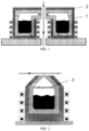
- FIG. 3 illustrates a crucible nozzle structure with automatic replenishment of molten metal.
- a nozzle 4 uses a wide outlet, and a heater 5 is also arranged at an upper part of the crucible for heating the crucible.
- the structure is spread by an arc 6 on one side, realizing lateral spraying; and a heating tube 7 is also arranged on the periphery of a crucible wall for heating the periphery surface.
- Application WO2018/020311A1 discloses a split crucible nozzle structure. As shown in FIG. 5 , in the device, the bottom of the crucible is connected to a molten metal supply tank 8, and the upper part of the supply tank 8 conveys metal steam to a tubular distributor and a steam nozzle at the front end through a split pipe 9; and then, the nozzle sprays the metal steam to a metal plate at a high speed.
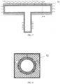
- Application CN103249860A discloses a split structure of a flow distributor and a nozzle. As shown in FIG. 6 , steam is delivered into an upper horizontal pipe 10 through a vertical pipe.
- the horizontal pipe 10 is provided with a multi-hole nozzle at the top to uniformly spray metal steam onto a surface of a metal plate.
- Application CN101175866A discloses a metal steam flow distributor and a nozzle form.
- a wire is wound outside a flow distributor pipe 11 to heat the pipe; and the nozzle has a square shell.
- a ringlike pipe made from another material is nested inside a square shell 12 and is used for spraying the metal steam.
- the steam outlet of the nozzle is multi-hole.
- WO 2014/168352 A1 relates to an evaporation deposition apparatus and an operating method thereof.
- the evaporation deposition apparatus comprises: a first cavity for receiving an evaporation material; a second cavity for receiving steam through the first cavity and a connection channel; an evaporator formed in the second cavity, including an outlet for radially discharging the steam having a point source, and formed of a conductive material; a reflective nozzle formed of a conductive material, connected to the outlet, and including a through-hole having a gradually-increased diameter; an inductive coil for covering the reflective nozzle and the evaporator; and an alternating current power source for applying alternating current electric power to the inductive coil.
- the inductive coil inductively heats the evaporator and the reflective nozzle to evaporate the evaporation material, and the steam is discharged through the reflective nozzle.
- the present invention aims to provide a vacuum coating device, which can form uniform coatings with consistent thickness and improve the yield of the coating.
- the yield of coating refers to the ratio of the width of the effective coating to the width of the strip steel, the effective coating can be understood as a coating with a thickness of 1 ⁇ 20 ⁇ m.
- the thickness deviation (d max -d min ) is less than or equal to 25%.
- the present invention provides the following technical solutions.
- a vacuum coating device for coating a steel plate comprising: a crucible (13), an induction heater (15) provided on the periphery of the crucible (13), a flow distribution box (17) connected to the top of said crucible (13) via a steam pipe (16), wherein said steam pipe (16) is provided with a pressure regulating valve (18), said flow distribution box (17) is provided inside with a horizontal pressure stabilizing plate (19), said flow distribution box (17) is connected on the top with a nozzle (20), a deflector (21) being arranged above said nozzle (20) along the emitting direction of the steam and wherein a distance Da from nozzle outlet to steel plate (100) is 10 ⁇ 200 mm, a height Db of said deflector (21) is 10 ⁇ 199 mm; a distance Dc from top of said deflector (21) to steel plate (100) is 1 ⁇ 190 mm; an angle Dd between said deflector (21) and said nozzle outlet is 60° ⁇ 135°; wherein Da, Db, Dc, and Dd satisfy
- the distance Da from said nozzle outlet to said steel plate is 10 ⁇ 200mm. Based on actual installation distance from the nozzle outlet to the steel plate, Da is usually greater than or equal to 10mm.
- Da ⁇ 200mm the injection angle of the steam increases, the injection range is large, and the coating thickness decreases, resulting in that the coating cannot have an effect of anti-erosion.
- the speed of steam ejecting to the steel plate decreases, leading to the poor adhesion and low density of the coating.
- the height Db of said deflector is 10 ⁇ 199mm. That height is determined by the distance between the nozzle outlet and the steel plate. When the nozzle outlet is very close to the steel plate, the height of the deflector reaches lower limit, which is 10mm; when the nozzle outlet is far from the steel plate, the height of the deflector reaches upper limit, which is 199mm.
- Da is usually greater than or equal to Db. That is, when the width of steel plate is less than the effective width of nozzle outlet, the deflector is flush with the edge of the steel plate in height.
- the distance Dc from the top of said deflector to steel plate is 1 ⁇ 190mm.
- Dc 1mm
- Dc 10mm
- the angle Dd between said deflector and said nozzle outlet is 60° ⁇ 135°.
- Dd can be less than 90° according to production needs.
- Dd can be 60°, and then a uniform coating can be obtained.
- a Dd of 135° can be adopted to improve the uniformity of the coating thickness at the edge of the steel plate.
- Dd is greater than 135°, the speed and range of the jet at the edge of the steel plate cannot be satisfied.
- Said pressure stabilizing plate is a pressure stabilizing plate made of multi-hole media. That type of pressure stabilizing plate filters gas through irregular holes that resemble honeycombs. And according to the production needs, different porosity can be used to change the steam distribution, so as to have uniform steam.
- said pressure stabilizing plate is of a multi-hole structure.
- the holes in said pressure stabilizing plate are rectangular, circle or triangular in shape. Or, the shape of holes can be arbitrary polygonal or circle. And those holes run in linear, curvilinear or have a multilayer structure in the direction of steam rise.
- the distribution direction of holes refers to the path of steam through the thickness direction of the pressure stabilizing plate. That is, when steam passes through the pressure stabilizing plate, not only the distribution of steam can be changed by the distribution of holes in the pressure stabilizing plate, but also the path of its rise can be changed by the direction of holes.
- the multilayer structure refers to a structure in which the distribution direction of holes directs the steam to rise in steps. For example, the multilayer structure can be steps formed by multiple sets of folds, which can increase the resistance of steam rise, but allow for more evenly distributed steam.
- Said nozzle outlet is of a slit shape or a multi-hole.
- the nozzle outlet is of a slit shape.
- the nozzle outlet is of a linear slit or a curvilinear slit.
- the slit shape refers to that the nozzle outlet is a whole slit rather than made up of multiple tiny slits set at intervals. That is because if the steam is emitted from each tiny slit, it will spread out to a certain extent, and the overlap area makes the coating thickness larger and does not form a uniform coating.
- the multi-hole nozzle outlet is rectangular, round or trapezoidal in shape.
- Said nozzle is made of graphite, ceramic or metal.
- the yield can reach more than 90%; and if the above relationships are not satisfied, the yield cannot reach 90%.
- the vacuum coating device further comprises a vacuum chamber, wherein both said flow distribution box and said steel plate are placed in said vacuum chamber.
- the present invention discloses a vacuum coating device for improving the yield of vacuum coating, where the metal steam is obtained by melting and evaporating the metal material in the crucible.
- the steam enters the flow distribution box through the pipe, the flow distribution box is arranged with a pressure stabilizing plate and other relative devices, and then the uniform steams can flow from the nozzle. Since a deflector is arranged at the top of said nozzle, even steam distribution can be given between the deflector and the steel strip to be coated.
- the deflection of the steam field at the edge of the steel strip can be adjusted by changing the distance between the deflector and the steel strip, thus improving the yield of the coating on the steel strip.
- the present invention is low cost, simple to operate, and can be exported in sets with vacuum coating technology in the future.
- the present invention provides a vacuum coating device.
- Said vacuum coating device is located underneath the steel plate 100 when in use.
- the vacuum coating device comprises a crucible 13, and the crucible 13 contains the molten metal 14.
- An induction heater 15 is arranged on the periphery of the crucible 13, the molten metal 14 and metal steam 22 can be obtained after the metal materials in crucible 13 are heated by the induction heater 15.
- the power of the induction heater 15 is adjustable, thus the pressure of the metal steam 22 in crucible 13 can be controlled.
- a flow distribution box 17 is connected to the top of said crucible 13 via a steam pipe 16, wherein said flow distribution box 17 and said steel plate 100 are placed in the vacuum chamber 23.
- a pressure regulating valve 18 is arranged in said steam pipe 16, the exchange between the steam in crucible 13 and the steam in the flow distribution box 17 and the vacuum chamber 23 can be blocked by the pressure regulating valve 18.
- a horizontal pressure stabilizing plate 19 is arranged in said flow distribution box 17, and a nozzle 20 is connected to the top of said flow distribution box 17.
- a deflector 21 is arranged at the top of said nozzle 20 along the direction of steam emission to increase the yield.
- said deflector 21 serves to make the steam through said nozzle outlet as vertical as possible towards said steel plate 100, avoiding flow deflection and thus increasing the yield of coating on the steel plate 100.
- the distance Da from the outlet of said nozzle 20 to said steel plate 100 is 10 ⁇ 200mm; the height Db of said deflector 21 is 10 ⁇ 199mm; the distance Dc from the top of said deflector 21 to said steel plate 100 is 1 ⁇ 190mm; the angle Dd between said deflector 21 and the outlet of said nozzle 20 is 60° ⁇ 135°.
- Da Db + Dc ;
- said nozzle 20 operates with an internal pressure of 500 ⁇ 500,000 Pa.
- the nozzle 20 is made of graphite, ceramic or inert metals, as well as other materials that are resistant to high temperature, wear and can be processed.
- said nozzle outlet is of a slit shape or multi-hole.
- the slit shape nozzle outlet is linear of curvilinear, and the multi-hole outlet is rectangular, round or trapezoidal in shape.
- said pressure stabilizing plate 19 has a multi-hole structure
- the holes in said pressure stabilizing plate are rectangular, circle or triangular in shape.
- the hole shape can be arbitrary polygonal or circle, the present application does not specifically limit the shape of the holes.
- those holes run in linear or curvilinear direction or have a multilayer structure.
- said molten metal 14 contains metals such as zinc, magnesium, aluminum, tin, nickel, copper, iron, etc., in addition to low melting point (below 2000°C) oxides of these metals.
- the steel plate 100 is cleaned by plasma or other devices before vacuum coating, and the preheating temperature reaches 80 ⁇ 300°C.
- the steel plate 100 is galvanized, and the width of the steel plate 100 is 1,000 mm. After cleaning and drying, the steel plate 100 is heated to 120°C. Zinc on steel plate surface is vaporized by the induction heater 15, and then adjust the power of the induction heater to raise the pressure in the crucible 13 to 20,000 Pa, at which point the pressure regulating valve 18 is closed. When the pressure in the crucible 13 reaches 20,000 Pa, the pressure regulating valve 18 is opened, and then the metal steam 22 enters into the flow distribution box 17 through the steam pipe 16.
- the pressure stabilizing plate in the flow distribution box 17 has a multi-hole structure or adopts a pressure stabilizing plate made of multi-hole media.
- the working pressure in the flow distribution box 17 is 5,000 Pa.
- the nozzle 20 is made of graphite, and the nozzle outlet is of a linear slit.
- the deflector 21 is rectangular, and the relevant parameters are as follows:
- the yield of coating reaches 95%.
Landscapes
- Chemical & Material Sciences (AREA)
- Chemical Kinetics & Catalysis (AREA)
- Engineering & Computer Science (AREA)
- Materials Engineering (AREA)
- Mechanical Engineering (AREA)
- Metallurgy (AREA)
- Organic Chemistry (AREA)
- Physical Vapour Deposition (AREA)
Claims (7)
- Eine Vakuumbeschichtungsvorrichtung zum Beschichten einer Stahlplatte (100), umfassend:einen Tiegel (13),eine Induktionsheizung (15), die auf dem Umfang des Tiegels (13) bereitgestellt ist,einen Strömungsverteilerkasten (17), der über eine Dampfleitung (16) mit der Oberseite des Tiegels (13) verbunden ist, wobeidie Dampfleitung (16) mit einem Druckregelventil (18) versehen ist, der Strömungsverteilerkasten (17) im Inneren mit einer horizontalen Druckstabilisierungsplatte (19) versehen ist, der Strömungsverteilerkasten (17) oben mit einer Düse (20) verbunden ist,einen Deflektor (21), der oberhalb der Düse (20) entlang der Austrittsrichtung des Dampfes angeordnet ist, und wobeider Abstand Da vom Düsenausgang zur Stahlplatte (100) 10-200 mm beträgt,eine Höhe Db des Deflektors (21) 10-199 mm beträgt;ein Abstand Dc von der Oberseite des Deflektors (21) zur Stahlplatte (100) 1-190 mm beträgt;ein Winkel Dd zwischen dem Deflektor (21) und dem Düsenausgang 60°~135° beträgt;wobei Da, Db, Dc und Dd die folgenden Beziehungen erfüllen:
 wenn Da=100-200 mm und Db=(1/5∼1/2)Da, Dd=60°~90°;wenn Da=100-200 mm und Db=(1/2∼2/3)Da, Dd=70°~110°;wenn Da=100-200 mm und Db=(2/3∼4/5)Da, Dd=80°~135°;wenn Da=10-100 mm und Db=(1/5∼1/2)Da, Dd=60°~100°;wenn Da=10-100 mm und Db=(1/2∼2/3)Da, Dd=70°~120°;wenn Da=10-100 mm und Db=(2/3∼4/5)Da, Dd=80°~135°.
 - Die Vakuumbeschichtungsvorrichtung zum Beschichten einer Stahlplatte (100) nach Anspruch 1, wobei die Druckstabilisierungsplatte (19) eine Mehrlochstruktur aufweist, wobei die Löcher rechteckig, kreisförmig oder dreieckig sind und in linearer oder gekrümmter Richtung verlaufen oder eine Mehrschichtstruktur haben.
- Die Vakuumbeschichtungsvorrichtung zum Beschichten einer Stahlplatte (100) nach Anspruch 1, wobei der Düsenauslass schlitzförmig oder mehrlochig ist.
- Die Vakuumbeschichtungsvorrichtung zum Beschichten einer Stahlplatte (100) nach Anspruch 3, wobei der Düsenauslass ein linearer Schlitz oder ein gekrümmter Schlitz ist.
- Die Vakuumbeschichtungsvorrichtung zum Beschichten einer Stahlplatte (100) nach Anspruch 3, wobei der Mehrlochdüsenauslass eine rechteckige, runde oder trapezförmige Form hat.
- Die Vakuumbeschichtungsvorrichtung zum Beschichten einer Stahlplatte (100) nach Anspruch 3, wobei die Düse (20) aus Graphit, Keramik oder Metall besteht.
- Die Vakuumbeschichtungsvorrichtung zum Beschichten einer Stahlplatte (100) nach Anspruch 1, die ferner eine Vakuumkammer (23) umfasst, wobei der Strömungsverteilerkasten (17) und die Stahlplatte (100) in der Vakuumkammer (23) angeordnet sind.
Applications Claiming Priority (2)
| Application Number | Priority Date | Filing Date | Title |
|---|---|---|---|
| CN201910915434.7A CN112553577A (zh) | 2019-09-26 | 2019-09-26 | 一种提高真空镀膜收得率的真空镀膜装置 |
| PCT/CN2020/117882 WO2021057921A1 (zh) | 2019-09-26 | 2020-09-25 | 一种真空镀膜装置 |
Publications (3)
| Publication Number | Publication Date |
|---|---|
| EP4029968A1 EP4029968A1 (de) | 2022-07-20 |
| EP4029968A4 EP4029968A4 (de) | 2022-12-07 |
| EP4029968B1 true EP4029968B1 (de) | 2025-06-04 |
Family
ID=75029726
Family Applications (1)
| Application Number | Title | Priority Date | Filing Date |
|---|---|---|---|
| EP20869963.7A Active EP4029968B1 (de) | 2019-09-26 | 2020-09-25 | Vakuumbeschichtungsanlage |
Country Status (6)
| Country | Link |
|---|---|
| US (1) | US20220325401A1 (de) |
| EP (1) | EP4029968B1 (de) |
| JP (1) | JP7412543B2 (de) |
| KR (1) | KR102749522B1 (de) |
| CN (1) | CN112553577A (de) |
| WO (1) | WO2021057921A1 (de) |
Families Citing this family (3)
| Publication number | Priority date | Publication date | Assignee | Title |
|---|---|---|---|---|
| CN112962081B (zh) * | 2021-02-01 | 2023-07-18 | 肇庆宏旺金属实业有限公司 | 一种钢板连续镀膜生产线及镀膜工艺 |
| CN115679269A (zh) * | 2021-07-30 | 2023-02-03 | 宝山钢铁股份有限公司 | 真空镀膜不稳定期的蒸汽捕集装置、真空镀膜装置及方法 |
| CN119506782B (zh) * | 2023-08-23 | 2025-11-14 | 宝山钢铁股份有限公司 | 一种调节金属蒸汽沉积宽度的真空镀膜装置及其控制方法 |
Citations (1)
| Publication number | Priority date | Publication date | Assignee | Title |
|---|---|---|---|---|
| CN207537525U (zh) * | 2017-11-29 | 2018-06-26 | 信利(惠州)智能显示有限公司 | 一种可自动调整倾斜角度的线性蒸镀源挡板 |
Family Cites Families (33)
| Publication number | Priority date | Publication date | Assignee | Title |
|---|---|---|---|---|
| US4552092A (en) | 1984-09-19 | 1985-11-12 | Mitsubishi Jukogyo Kabushiki Kaisha | Vacuum vapor deposition system |
| US5002837A (en) * | 1988-07-06 | 1991-03-26 | Kabushiki Kaisha Kobe Seiko Sho | Zn-Mg alloy vapor deposition plated metals of high corrosion resistance, as well as method of producing them |
| BE1009321A6 (fr) | 1995-05-17 | 1997-02-04 | Centre Rech Metallurgique | Dispositif de revetement d'une bande d'acier galvanisee. |
| BE1009317A6 (fr) | 1995-05-10 | 1997-02-04 | Centre Rech Metallurgique | Dispositif et installation pour revetir une bande d'acier. |
| US7393416B2 (en) * | 2002-08-27 | 2008-07-01 | General Electric Company | Vapor deposition process and apparatus therefor |
| ATE471997T1 (de) | 2005-05-31 | 2010-07-15 | Corus Technology Bv | Vorrichtung und verfahren zum beschichten eines substrats |
| JP2007092149A (ja) * | 2005-09-29 | 2007-04-12 | Tokyo Electron Ltd | 原料供給装置および蒸着装置 |
| JP5063969B2 (ja) * | 2006-09-29 | 2012-10-31 | 東京エレクトロン株式会社 | 蒸着装置、蒸着装置の制御装置、蒸着装置の制御方法および蒸着装置の使用方法 |
| EP2048261A1 (de) * | 2007-10-12 | 2009-04-15 | ArcelorMittal France | Industrieller Dampferzeuger zum Aufbringen einer Legierungsschicht auf einem Metallband |
| JP4782219B2 (ja) * | 2009-07-02 | 2011-09-28 | 三菱重工業株式会社 | 真空蒸着装置 |
| WO2012081738A1 (en) | 2010-12-13 | 2012-06-21 | Posco | Continuous coating apparatus |
| CN101988185A (zh) * | 2010-12-14 | 2011-03-23 | 无锡虹彩科技发展有限公司 | 镀膜源、真空镀膜装置及其镀膜工艺 |
| KR101942471B1 (ko) * | 2012-06-15 | 2019-01-28 | 삼성디스플레이 주식회사 | 증착 장치 및 이를 이용한 유기 발광 표시장치의 제조방법 |
| KR101422533B1 (ko) * | 2012-12-04 | 2014-07-24 | 주식회사 선익시스템 | 믹싱 영역이 포함된 선형 증발원 |
| KR101461738B1 (ko) * | 2012-12-21 | 2014-11-14 | 주식회사 포스코 | 가열장치 및 이를 포함하는 코팅 시스템 |
| KR101465615B1 (ko) * | 2013-04-11 | 2014-11-27 | 한국표준과학연구원 | 증발 증착 장치 |
| JP2015010257A (ja) * | 2013-06-28 | 2015-01-19 | 株式会社日立ハイテクファインシステムズ | 真空蒸着装置の蒸発源並びにそれを用いた真空蒸着装置及び真空蒸着方法 |
| US20150040970A1 (en) * | 2013-08-06 | 2015-02-12 | First Solar, Inc. | Vacuum Deposition System For Solar Cell Production And Method Of Manufacturing |
| JP6594986B2 (ja) * | 2014-11-07 | 2019-10-23 | アプライド マテリアルズ インコーポレイテッド | 真空堆積のための材料源アレンジメント及び材料分配アレンジメント |
| KR102307431B1 (ko) * | 2015-01-22 | 2021-09-30 | 삼성디스플레이 주식회사 | 복수의 모듈을 갖는 증착원 |
| JP2017025355A (ja) * | 2015-07-16 | 2017-02-02 | パナソニックIpマネジメント株式会社 | 蒸着装置及び蒸着方法 |
| KR20180015250A (ko) * | 2015-07-28 | 2018-02-12 | 샤프 가부시키가이샤 | 증착원, 증착 장치 및 증착막 제조 방법 |
| WO2018020296A1 (en) | 2016-07-27 | 2018-02-01 | Arcelormittal | Apparatus and method for vacuum deposition |
| CN206289295U (zh) * | 2016-11-30 | 2017-06-30 | 信利(惠州)智能显示有限公司 | 一种线性蒸发源 |
| CN106637088B (zh) * | 2016-12-09 | 2019-05-24 | 合肥鑫晟光电科技有限公司 | 一种喷嘴挡板及蒸镀装置 |
| CN206438173U (zh) * | 2017-02-15 | 2017-08-25 | 京东方科技集团股份有限公司 | 蒸发源装置及蒸发镀膜设备 |
| KR102369676B1 (ko) * | 2017-04-10 | 2022-03-04 | 삼성디스플레이 주식회사 | 표시 장치의 제조장치 및 표시 장치의 제조방법 |
| US20180327895A1 (en) * | 2017-05-12 | 2018-11-15 | Junying MU | Evaporation apparatus |
| KR102367988B1 (ko) * | 2017-07-31 | 2022-02-28 | 삼성디스플레이 주식회사 | 표시 장치의 제조장치 및 표시 장치의 제조방법 |
| WO2019043422A1 (en) * | 2017-08-30 | 2019-03-07 | Arcelormittal | COATED METALLIC SUBSTRATE |
| CN107815648B (zh) * | 2017-09-26 | 2019-11-05 | 上海升翕光电科技有限公司 | 一种线性蒸发源装置及蒸镀设备 |
| CN108103442A (zh) * | 2017-12-29 | 2018-06-01 | 上海升翕光电科技有限公司 | 一种oled线性蒸发源结构 |
| CN109487216A (zh) * | 2018-12-29 | 2019-03-19 | 深圳市华星光电半导体显示技术有限公司 | 线源装置和oled蒸镀机 |
-
2019
- 2019-09-26 CN CN201910915434.7A patent/CN112553577A/zh active Pending
-
2020
- 2020-09-25 WO PCT/CN2020/117882 patent/WO2021057921A1/zh not_active Ceased
- 2020-09-25 US US17/763,837 patent/US20220325401A1/en not_active Abandoned
- 2020-09-25 EP EP20869963.7A patent/EP4029968B1/de active Active
- 2020-09-25 JP JP2022519383A patent/JP7412543B2/ja active Active
- 2020-09-25 KR KR1020227010370A patent/KR102749522B1/ko active Active
Patent Citations (1)
| Publication number | Priority date | Publication date | Assignee | Title |
|---|---|---|---|---|
| CN207537525U (zh) * | 2017-11-29 | 2018-06-26 | 信利(惠州)智能显示有限公司 | 一种可自动调整倾斜角度的线性蒸镀源挡板 |
Also Published As
| Publication number | Publication date |
|---|---|
| WO2021057921A1 (zh) | 2021-04-01 |
| JP2022549906A (ja) | 2022-11-29 |
| KR102749522B1 (ko) | 2025-01-03 |
| EP4029968A1 (de) | 2022-07-20 |
| JP7412543B2 (ja) | 2024-01-12 |
| KR20220053646A (ko) | 2022-04-29 |
| CN112553577A (zh) | 2021-03-26 |
| EP4029968A4 (de) | 2022-12-07 |
| US20220325401A1 (en) | 2022-10-13 |
Similar Documents
| Publication | Publication Date | Title |
|---|---|---|
| EP4029968B1 (de) | Vakuumbeschichtungsanlage | |
| JP6650442B2 (ja) | 構成部品、バンド状の材料又はツールの表面にコーティングを形成する装置 | |
| US12534795B2 (en) | Vacuum coating device for uniformly distributing metal steam by using guide plate type structure | |
| KR102827828B1 (ko) | 균일한 혼합 버퍼 구조를 이용한 금속증기의 분배를 위한 진공코팅장치 | |
| EP4012067B1 (de) | Vakuumbeschichtungsvorrichtung | |
| EP4023788B1 (de) | Vakuumbeschichtungsvorrichtung | |
| CN112708855B (zh) | 一种具有导流式真空镀膜喷嘴的真空镀膜装置 | |
| CN113957390B (zh) | 一种具有气垫缓冲腔的真空镀膜装置 | |
| CN113957391B (zh) | 一种采用芯棒加热结构均匀分配金属蒸汽的真空镀膜装置 | |
| US12618143B2 (en) | Vacuum coating apparatus for uniformly distributing metal vapor using uniform mixing buffer structure | |
| CN113957389B (zh) | 一种具有多孔降噪及均匀化分配金属蒸汽的真空镀膜装置 | |
| CN112575294B (zh) | 一种具有双隔板的真空镀膜装置 | |
| CN112553579B (zh) | 一种具有过滤及均匀化喷嘴的真空镀膜装置 |
Legal Events
| Date | Code | Title | Description |
|---|---|---|---|
| STAA | Information on the status of an ep patent application or granted ep patent |
Free format text: STATUS: THE INTERNATIONAL PUBLICATION HAS BEEN MADE |
|
| PUAI | Public reference made under article 153(3) epc to a published international application that has entered the european phase |
Free format text: ORIGINAL CODE: 0009012 |
|
| STAA | Information on the status of an ep patent application or granted ep patent |
Free format text: STATUS: REQUEST FOR EXAMINATION WAS MADE |
|
| 17P | Request for examination filed |
Effective date: 20220411 |
|
| AK | Designated contracting states |
Kind code of ref document: A1 Designated state(s): AL AT BE BG CH CY CZ DE DK EE ES FI FR GB GR HR HU IE IS IT LI LT LU LV MC MK MT NL NO PL PT RO RS SE SI SK SM TR |
|
| A4 | Supplementary search report drawn up and despatched |
Effective date: 20221108 |
|
| RIC1 | Information provided on ipc code assigned before grant |
Ipc: C23C 14/56 20060101ALI20221102BHEP Ipc: C23C 14/26 20060101ALI20221102BHEP Ipc: C23C 14/16 20060101ALI20221102BHEP Ipc: C23C 14/24 20060101AFI20221102BHEP |
|
| DAV | Request for validation of the european patent (deleted) | ||
| DAX | Request for extension of the european patent (deleted) | ||
| STAA | Information on the status of an ep patent application or granted ep patent |
Free format text: STATUS: EXAMINATION IS IN PROGRESS |
|
| 17Q | First examination report despatched |
Effective date: 20230725 |
|
| GRAP | Despatch of communication of intention to grant a patent |
Free format text: ORIGINAL CODE: EPIDOSNIGR1 |
|
| STAA | Information on the status of an ep patent application or granted ep patent |
Free format text: STATUS: GRANT OF PATENT IS INTENDED |
|
| GRAJ | Information related to disapproval of communication of intention to grant by the applicant or resumption of examination proceedings by the epo deleted |
Free format text: ORIGINAL CODE: EPIDOSDIGR1 |
|
| STAA | Information on the status of an ep patent application or granted ep patent |
Free format text: STATUS: EXAMINATION IS IN PROGRESS |
|
| GRAP | Despatch of communication of intention to grant a patent |
Free format text: ORIGINAL CODE: EPIDOSNIGR1 |
|
| STAA | Information on the status of an ep patent application or granted ep patent |
Free format text: STATUS: GRANT OF PATENT IS INTENDED |
|
| GRAJ | Information related to disapproval of communication of intention to grant by the applicant or resumption of examination proceedings by the epo deleted |
Free format text: ORIGINAL CODE: EPIDOSDIGR1 |
|
| GRAP | Despatch of communication of intention to grant a patent |
Free format text: ORIGINAL CODE: EPIDOSNIGR1 |
|
| GRAJ | Information related to disapproval of communication of intention to grant by the applicant or resumption of examination proceedings by the epo deleted |
Free format text: ORIGINAL CODE: EPIDOSDIGR1 |
|
| STAA | Information on the status of an ep patent application or granted ep patent |
Free format text: STATUS: EXAMINATION IS IN PROGRESS |
|
| GRAP | Despatch of communication of intention to grant a patent |
Free format text: ORIGINAL CODE: EPIDOSNIGR1 |
|
| STAA | Information on the status of an ep patent application or granted ep patent |
Free format text: STATUS: GRANT OF PATENT IS INTENDED |
|
| GRAJ | Information related to disapproval of communication of intention to grant by the applicant or resumption of examination proceedings by the epo deleted |
Free format text: ORIGINAL CODE: EPIDOSDIGR1 |
|
| GRAP | Despatch of communication of intention to grant a patent |
Free format text: ORIGINAL CODE: EPIDOSNIGR1 |
|
| INTG | Intention to grant announced |
Effective date: 20241008 |
|
| GRAJ | Information related to disapproval of communication of intention to grant by the applicant or resumption of examination proceedings by the epo deleted |
Free format text: ORIGINAL CODE: EPIDOSDIGR1 |
|
| STAA | Information on the status of an ep patent application or granted ep patent |
Free format text: STATUS: EXAMINATION IS IN PROGRESS |
|
| INTC | Intention to grant announced (deleted) | ||
| GRAP | Despatch of communication of intention to grant a patent |
Free format text: ORIGINAL CODE: EPIDOSNIGR1 |
|
| STAA | Information on the status of an ep patent application or granted ep patent |
Free format text: STATUS: GRANT OF PATENT IS INTENDED |
|
| INTG | Intention to grant announced |
Effective date: 20241022 |
|
| INTC | Intention to grant announced (deleted) | ||
| INTG | Intention to grant announced |
Effective date: 20241106 |
|
| INTG | Intention to grant announced |
Effective date: 20241118 |
|
| P01 | Opt-out of the competence of the unified patent court (upc) registered |
Free format text: CASE NUMBER: APP_3154/2025 Effective date: 20250120 |
|
| GRAS | Grant fee paid |
Free format text: ORIGINAL CODE: EPIDOSNIGR3 |
|
| GRAA | (expected) grant |
Free format text: ORIGINAL CODE: 0009210 |
|
| STAA | Information on the status of an ep patent application or granted ep patent |
Free format text: STATUS: THE PATENT HAS BEEN GRANTED |
|
| AK | Designated contracting states |
Kind code of ref document: B1 Designated state(s): AL AT BE BG CH CY CZ DE DK EE ES FI FR GB GR HR HU IE IS IT LI LT LU LV MC MK MT NL NO PL PT RO RS SE SI SK SM TR |
|
| REG | Reference to a national code |
Ref country code: GB Ref legal event code: FG4D |
|
| REG | Reference to a national code |
Ref country code: CH Ref legal event code: EP |
|
| REG | Reference to a national code |
Ref country code: DE Ref legal event code: R096 Ref document number: 602020052433 Country of ref document: DE |
|
| REG | Reference to a national code |
Ref country code: IE Ref legal event code: FG4D |
|
| REG | Reference to a national code |
Ref country code: NL Ref legal event code: MP Effective date: 20250604 |
|
| PG25 | Lapsed in a contracting state [announced via postgrant information from national office to epo] |
Ref country code: FI Free format text: LAPSE BECAUSE OF FAILURE TO SUBMIT A TRANSLATION OF THE DESCRIPTION OR TO PAY THE FEE WITHIN THE PRESCRIBED TIME-LIMIT Effective date: 20250604 Ref country code: ES Free format text: LAPSE BECAUSE OF FAILURE TO SUBMIT A TRANSLATION OF THE DESCRIPTION OR TO PAY THE FEE WITHIN THE PRESCRIBED TIME-LIMIT Effective date: 20250604 |
|
| PGFP | Annual fee paid to national office [announced via postgrant information from national office to epo] |
Ref country code: DE Payment date: 20250916 Year of fee payment: 6 |
|
| REG | Reference to a national code |
Ref country code: LT Ref legal event code: MG9D |
|
| PG25 | Lapsed in a contracting state [announced via postgrant information from national office to epo] |
Ref country code: NO Free format text: LAPSE BECAUSE OF FAILURE TO SUBMIT A TRANSLATION OF THE DESCRIPTION OR TO PAY THE FEE WITHIN THE PRESCRIBED TIME-LIMIT Effective date: 20250904 Ref country code: GR Free format text: LAPSE BECAUSE OF FAILURE TO SUBMIT A TRANSLATION OF THE DESCRIPTION OR TO PAY THE FEE WITHIN THE PRESCRIBED TIME-LIMIT Effective date: 20250905 |
|
| PG25 | Lapsed in a contracting state [announced via postgrant information from national office to epo] |
Ref country code: PL Free format text: LAPSE BECAUSE OF FAILURE TO SUBMIT A TRANSLATION OF THE DESCRIPTION OR TO PAY THE FEE WITHIN THE PRESCRIBED TIME-LIMIT Effective date: 20250604 |
|
| PG25 | Lapsed in a contracting state [announced via postgrant information from national office to epo] |
Ref country code: BG Free format text: LAPSE BECAUSE OF FAILURE TO SUBMIT A TRANSLATION OF THE DESCRIPTION OR TO PAY THE FEE WITHIN THE PRESCRIBED TIME-LIMIT Effective date: 20250604 |
|
| PGFP | Annual fee paid to national office [announced via postgrant information from national office to epo] |
Ref country code: BE Payment date: 20250919 Year of fee payment: 6 |
|
| PG25 | Lapsed in a contracting state [announced via postgrant information from national office to epo] |
Ref country code: HR Free format text: LAPSE BECAUSE OF FAILURE TO SUBMIT A TRANSLATION OF THE DESCRIPTION OR TO PAY THE FEE WITHIN THE PRESCRIBED TIME-LIMIT Effective date: 20250604 |
|
| PGFP | Annual fee paid to national office [announced via postgrant information from national office to epo] |
Ref country code: FR Payment date: 20250929 Year of fee payment: 6 |
|
| PG25 | Lapsed in a contracting state [announced via postgrant information from national office to epo] |
Ref country code: RS Free format text: LAPSE BECAUSE OF FAILURE TO SUBMIT A TRANSLATION OF THE DESCRIPTION OR TO PAY THE FEE WITHIN THE PRESCRIBED TIME-LIMIT Effective date: 20250904 |
|
| PG25 | Lapsed in a contracting state [announced via postgrant information from national office to epo] |
Ref country code: LV Free format text: LAPSE BECAUSE OF FAILURE TO SUBMIT A TRANSLATION OF THE DESCRIPTION OR TO PAY THE FEE WITHIN THE PRESCRIBED TIME-LIMIT Effective date: 20250604 |
|
| PG25 | Lapsed in a contracting state [announced via postgrant information from national office to epo] |
Ref country code: NL Free format text: LAPSE BECAUSE OF FAILURE TO SUBMIT A TRANSLATION OF THE DESCRIPTION OR TO PAY THE FEE WITHIN THE PRESCRIBED TIME-LIMIT Effective date: 20250604 |
|
| PG25 | Lapsed in a contracting state [announced via postgrant information from national office to epo] |
Ref country code: PT Free format text: LAPSE BECAUSE OF FAILURE TO SUBMIT A TRANSLATION OF THE DESCRIPTION OR TO PAY THE FEE WITHIN THE PRESCRIBED TIME-LIMIT Effective date: 20251006 |
|
| REG | Reference to a national code |
Ref country code: AT Ref legal event code: MK05 Ref document number: 1800395 Country of ref document: AT Kind code of ref document: T Effective date: 20250604 |
|
| PG25 | Lapsed in a contracting state [announced via postgrant information from national office to epo] |
Ref country code: IS Free format text: LAPSE BECAUSE OF FAILURE TO SUBMIT A TRANSLATION OF THE DESCRIPTION OR TO PAY THE FEE WITHIN THE PRESCRIBED TIME-LIMIT Effective date: 20251004 |
|
| PG25 | Lapsed in a contracting state [announced via postgrant information from national office to epo] |
Ref country code: AT Free format text: LAPSE BECAUSE OF FAILURE TO SUBMIT A TRANSLATION OF THE DESCRIPTION OR TO PAY THE FEE WITHIN THE PRESCRIBED TIME-LIMIT Effective date: 20250604 Ref country code: SM Free format text: LAPSE BECAUSE OF FAILURE TO SUBMIT A TRANSLATION OF THE DESCRIPTION OR TO PAY THE FEE WITHIN THE PRESCRIBED TIME-LIMIT Effective date: 20250604 |
|
| PG25 | Lapsed in a contracting state [announced via postgrant information from national office to epo] |
Ref country code: CZ Free format text: LAPSE BECAUSE OF FAILURE TO SUBMIT A TRANSLATION OF THE DESCRIPTION OR TO PAY THE FEE WITHIN THE PRESCRIBED TIME-LIMIT Effective date: 20250604 |
|
| PG25 | Lapsed in a contracting state [announced via postgrant information from national office to epo] |
Ref country code: EE Free format text: LAPSE BECAUSE OF FAILURE TO SUBMIT A TRANSLATION OF THE DESCRIPTION OR TO PAY THE FEE WITHIN THE PRESCRIBED TIME-LIMIT Effective date: 20250604 |
|
| PG25 | Lapsed in a contracting state [announced via postgrant information from national office to epo] |
Ref country code: RO Free format text: LAPSE BECAUSE OF FAILURE TO SUBMIT A TRANSLATION OF THE DESCRIPTION OR TO PAY THE FEE WITHIN THE PRESCRIBED TIME-LIMIT Effective date: 20250604 Ref country code: SK Free format text: LAPSE BECAUSE OF FAILURE TO SUBMIT A TRANSLATION OF THE DESCRIPTION OR TO PAY THE FEE WITHIN THE PRESCRIBED TIME-LIMIT Effective date: 20250604 |
|
| PG25 | Lapsed in a contracting state [announced via postgrant information from national office to epo] |
Ref country code: IT Free format text: LAPSE BECAUSE OF FAILURE TO SUBMIT A TRANSLATION OF THE DESCRIPTION OR TO PAY THE FEE WITHIN THE PRESCRIBED TIME-LIMIT Effective date: 20250604 |
|
| REG | Reference to a national code |
Ref country code: DE Ref legal event code: R097 Ref document number: 602020052433 Country of ref document: DE |
|
| PLBE | No opposition filed within time limit |
Free format text: ORIGINAL CODE: 0009261 |
|
| STAA | Information on the status of an ep patent application or granted ep patent |
Free format text: STATUS: NO OPPOSITION FILED WITHIN TIME LIMIT |
|
| PG25 | Lapsed in a contracting state [announced via postgrant information from national office to epo] |
Ref country code: DK Free format text: LAPSE BECAUSE OF FAILURE TO SUBMIT A TRANSLATION OF THE DESCRIPTION OR TO PAY THE FEE WITHIN THE PRESCRIBED TIME-LIMIT Effective date: 20250604 |
|
| REG | Reference to a national code |
Ref country code: CH Ref legal event code: L10 Free format text: ST27 STATUS EVENT CODE: U-0-0-L10-L00 (AS PROVIDED BY THE NATIONAL OFFICE) Effective date: 20260416 |