EP4024601A1 - Stromschiene mit ausgezeichneter feuersicherheit - Google Patents
Stromschiene mit ausgezeichneter feuersicherheit Download PDFInfo
- Publication number
- EP4024601A1 EP4024601A1 EP21804617.5A EP21804617A EP4024601A1 EP 4024601 A1 EP4024601 A1 EP 4024601A1 EP 21804617 A EP21804617 A EP 21804617A EP 4024601 A1 EP4024601 A1 EP 4024601A1
- Authority
- EP
- European Patent Office
- Prior art keywords
- metal
- bar
- bus bar
- metal bar
- fire
- Prior art date
- Legal status (The legal status is an assumption and is not a legal conclusion. Google has not performed a legal analysis and makes no representation as to the accuracy of the status listed.)
- Pending
Links
Images


Classifications
-
- H—ELECTRICITY
- H01—ELECTRIC ELEMENTS
- H01B—CABLES; CONDUCTORS; INSULATORS; SELECTION OF MATERIALS FOR THEIR CONDUCTIVE, INSULATING OR DIELECTRIC PROPERTIES
- H01B7/00—Insulated conductors or cables characterised by their form
- H01B7/02—Disposition of insulation
-
- H—ELECTRICITY
- H01—ELECTRIC ELEMENTS
- H01M—PROCESSES OR MEANS, e.g. BATTERIES, FOR THE DIRECT CONVERSION OF CHEMICAL ENERGY INTO ELECTRICAL ENERGY
- H01M50/00—Constructional details or processes of manufacture of the non-active parts of electrochemical cells other than fuel cells, e.g. hybrid cells
- H01M50/50—Current conducting connections for cells or batteries
- H01M50/572—Means for preventing undesired use or discharge
-
- A—HUMAN NECESSITIES
- A62—LIFE-SAVING; FIRE-FIGHTING
- A62C—FIRE-FIGHTING
- A62C3/00—Fire prevention, containment or extinguishing specially adapted for particular objects or places
- A62C3/16—Fire prevention, containment or extinguishing specially adapted for particular objects or places in electrical installations, e.g. cableways
-
- C—CHEMISTRY; METALLURGY
- C09—DYES; PAINTS; POLISHES; NATURAL RESINS; ADHESIVES; COMPOSITIONS NOT OTHERWISE PROVIDED FOR; APPLICATIONS OF MATERIALS NOT OTHERWISE PROVIDED FOR
- C09J—ADHESIVES; NON-MECHANICAL ASPECTS OF ADHESIVE PROCESSES IN GENERAL; ADHESIVE PROCESSES NOT PROVIDED FOR ELSEWHERE; USE OF MATERIALS AS ADHESIVES
- C09J1/00—Adhesives based on inorganic constituents
-
- C—CHEMISTRY; METALLURGY
- C09—DYES; PAINTS; POLISHES; NATURAL RESINS; ADHESIVES; COMPOSITIONS NOT OTHERWISE PROVIDED FOR; APPLICATIONS OF MATERIALS NOT OTHERWISE PROVIDED FOR
- C09J—ADHESIVES; NON-MECHANICAL ASPECTS OF ADHESIVE PROCESSES IN GENERAL; ADHESIVE PROCESSES NOT PROVIDED FOR ELSEWHERE; USE OF MATERIALS AS ADHESIVES
- C09J7/00—Adhesives in the form of films or foils
- C09J7/30—Adhesives in the form of films or foils characterised by the adhesive composition
-
- H—ELECTRICITY
- H01—ELECTRIC ELEMENTS
- H01B—CABLES; CONDUCTORS; INSULATORS; SELECTION OF MATERIALS FOR THEIR CONDUCTIVE, INSULATING OR DIELECTRIC PROPERTIES
- H01B7/00—Insulated conductors or cables characterised by their form
- H01B7/0009—Details relating to the conductive cores
-
- H—ELECTRICITY
- H01—ELECTRIC ELEMENTS
- H01B—CABLES; CONDUCTORS; INSULATORS; SELECTION OF MATERIALS FOR THEIR CONDUCTIVE, INSULATING OR DIELECTRIC PROPERTIES
- H01B7/00—Insulated conductors or cables characterised by their form
- H01B7/17—Protection against damage caused by external factors, e.g. sheaths or armouring
- H01B7/29—Protection against damage caused by extremes of temperature or by flame
- H01B7/295—Protection against damage caused by extremes of temperature or by flame using material resistant to flame
-
- H—ELECTRICITY
- H01—ELECTRIC ELEMENTS
- H01M—PROCESSES OR MEANS, e.g. BATTERIES, FOR THE DIRECT CONVERSION OF CHEMICAL ENERGY INTO ELECTRICAL ENERGY
- H01M50/00—Constructional details or processes of manufacture of the non-active parts of electrochemical cells other than fuel cells, e.g. hybrid cells
- H01M50/30—Arrangements for facilitating escape of gases
- H01M50/383—Flame arresting or ignition-preventing means
-
- H—ELECTRICITY
- H01—ELECTRIC ELEMENTS
- H01M—PROCESSES OR MEANS, e.g. BATTERIES, FOR THE DIRECT CONVERSION OF CHEMICAL ENERGY INTO ELECTRICAL ENERGY
- H01M50/00—Constructional details or processes of manufacture of the non-active parts of electrochemical cells other than fuel cells, e.g. hybrid cells
- H01M50/50—Current conducting connections for cells or batteries
- H01M50/502—Interconnectors for connecting terminals of adjacent batteries; Interconnectors for connecting cells outside a battery casing
- H01M50/503—Interconnectors for connecting terminals of adjacent batteries; Interconnectors for connecting cells outside a battery casing characterised by the shape of the interconnectors
-
- H—ELECTRICITY
- H01—ELECTRIC ELEMENTS
- H01M—PROCESSES OR MEANS, e.g. BATTERIES, FOR THE DIRECT CONVERSION OF CHEMICAL ENERGY INTO ELECTRICAL ENERGY
- H01M50/00—Constructional details or processes of manufacture of the non-active parts of electrochemical cells other than fuel cells, e.g. hybrid cells
- H01M50/50—Current conducting connections for cells or batteries
- H01M50/502—Interconnectors for connecting terminals of adjacent batteries; Interconnectors for connecting cells outside a battery casing
- H01M50/505—Interconnectors for connecting terminals of adjacent batteries; Interconnectors for connecting cells outside a battery casing comprising a single busbar
-
- H—ELECTRICITY
- H01—ELECTRIC ELEMENTS
- H01M—PROCESSES OR MEANS, e.g. BATTERIES, FOR THE DIRECT CONVERSION OF CHEMICAL ENERGY INTO ELECTRICAL ENERGY
- H01M50/00—Constructional details or processes of manufacture of the non-active parts of electrochemical cells other than fuel cells, e.g. hybrid cells
- H01M50/50—Current conducting connections for cells or batteries
- H01M50/502—Interconnectors for connecting terminals of adjacent batteries; Interconnectors for connecting cells outside a battery casing
- H01M50/521—Interconnectors for connecting terminals of adjacent batteries; Interconnectors for connecting cells outside a battery casing characterised by the material
- H01M50/522—Inorganic material
-
- H—ELECTRICITY
- H01—ELECTRIC ELEMENTS
- H01M—PROCESSES OR MEANS, e.g. BATTERIES, FOR THE DIRECT CONVERSION OF CHEMICAL ENERGY INTO ELECTRICAL ENERGY
- H01M50/00—Constructional details or processes of manufacture of the non-active parts of electrochemical cells other than fuel cells, e.g. hybrid cells
- H01M50/50—Current conducting connections for cells or batteries
- H01M50/502—Interconnectors for connecting terminals of adjacent batteries; Interconnectors for connecting cells outside a battery casing
- H01M50/521—Interconnectors for connecting terminals of adjacent batteries; Interconnectors for connecting cells outside a battery casing characterised by the material
- H01M50/526—Interconnectors for connecting terminals of adjacent batteries; Interconnectors for connecting cells outside a battery casing characterised by the material having a layered structure
-
- H—ELECTRICITY
- H01—ELECTRIC ELEMENTS
- H01M—PROCESSES OR MEANS, e.g. BATTERIES, FOR THE DIRECT CONVERSION OF CHEMICAL ENERGY INTO ELECTRICAL ENERGY
- H01M50/00—Constructional details or processes of manufacture of the non-active parts of electrochemical cells other than fuel cells, e.g. hybrid cells
- H01M50/50—Current conducting connections for cells or batteries
- H01M50/572—Means for preventing undesired use or discharge
- H01M50/584—Means for preventing undesired use or discharge for preventing incorrect connections inside or outside the batteries
- H01M50/588—Means for preventing undesired use or discharge for preventing incorrect connections inside or outside the batteries outside the batteries, e.g. incorrect connections of terminals or busbars
-
- H—ELECTRICITY
- H01—ELECTRIC ELEMENTS
- H01M—PROCESSES OR MEANS, e.g. BATTERIES, FOR THE DIRECT CONVERSION OF CHEMICAL ENERGY INTO ELECTRICAL ENERGY
- H01M50/00—Constructional details or processes of manufacture of the non-active parts of electrochemical cells other than fuel cells, e.g. hybrid cells
- H01M50/50—Current conducting connections for cells or batteries
- H01M50/572—Means for preventing undesired use or discharge
- H01M50/584—Means for preventing undesired use or discharge for preventing incorrect connections inside or outside the batteries
- H01M50/59—Means for preventing undesired use or discharge for preventing incorrect connections inside or outside the batteries characterised by the protection means
- H01M50/593—Spacers; Insulating plates
-
- H—ELECTRICITY
- H01—ELECTRIC ELEMENTS
- H01M—PROCESSES OR MEANS, e.g. BATTERIES, FOR THE DIRECT CONVERSION OF CHEMICAL ENERGY INTO ELECTRICAL ENERGY
- H01M50/00—Constructional details or processes of manufacture of the non-active parts of electrochemical cells other than fuel cells, e.g. hybrid cells
- H01M50/50—Current conducting connections for cells or batteries
- H01M50/572—Means for preventing undesired use or discharge
- H01M50/584—Means for preventing undesired use or discharge for preventing incorrect connections inside or outside the batteries
- H01M50/59—Means for preventing undesired use or discharge for preventing incorrect connections inside or outside the batteries characterised by the protection means
- H01M50/597—Protection against reversal of polarity
-
- H—ELECTRICITY
- H01—ELECTRIC ELEMENTS
- H01R—ELECTRICALLY-CONDUCTIVE CONNECTIONS; STRUCTURAL ASSOCIATIONS OF A PLURALITY OF MUTUALLY-INSULATED ELECTRICAL CONNECTING ELEMENTS; COUPLING DEVICES; CURRENT COLLECTORS
- H01R13/00—Details of coupling devices of the kinds covered by groups H01R12/70 or H01R24/00 - H01R33/00
- H01R13/46—Bases; Cases
- H01R13/52—Dustproof, splashproof, drip-proof, waterproof, or flameproof cases
- H01R13/527—Flameproof cases
-
- C—CHEMISTRY; METALLURGY
- C09—DYES; PAINTS; POLISHES; NATURAL RESINS; ADHESIVES; COMPOSITIONS NOT OTHERWISE PROVIDED FOR; APPLICATIONS OF MATERIALS NOT OTHERWISE PROVIDED FOR
- C09J—ADHESIVES; NON-MECHANICAL ASPECTS OF ADHESIVE PROCESSES IN GENERAL; ADHESIVE PROCESSES NOT PROVIDED FOR ELSEWHERE; USE OF MATERIALS AS ADHESIVES
- C09J2203/00—Applications of adhesives in processes or use of adhesives in the form of films or foils
- C09J2203/33—Applications of adhesives in processes or use of adhesives in the form of films or foils for batteries or fuel cells
-
- C—CHEMISTRY; METALLURGY
- C09—DYES; PAINTS; POLISHES; NATURAL RESINS; ADHESIVES; COMPOSITIONS NOT OTHERWISE PROVIDED FOR; APPLICATIONS OF MATERIALS NOT OTHERWISE PROVIDED FOR
- C09J—ADHESIVES; NON-MECHANICAL ASPECTS OF ADHESIVE PROCESSES IN GENERAL; ADHESIVE PROCESSES NOT PROVIDED FOR ELSEWHERE; USE OF MATERIALS AS ADHESIVES
- C09J2301/00—Additional features of adhesives in the form of films or foils
- C09J2301/30—Additional features of adhesives in the form of films or foils characterized by the chemical, physicochemical or physical properties of the adhesive or the carrier
- C09J2301/312—Additional features of adhesives in the form of films or foils characterized by the chemical, physicochemical or physical properties of the adhesive or the carrier parameters being the characterizing feature
-
- C—CHEMISTRY; METALLURGY
- C09—DYES; PAINTS; POLISHES; NATURAL RESINS; ADHESIVES; COMPOSITIONS NOT OTHERWISE PROVIDED FOR; APPLICATIONS OF MATERIALS NOT OTHERWISE PROVIDED FOR
- C09J—ADHESIVES; NON-MECHANICAL ASPECTS OF ADHESIVE PROCESSES IN GENERAL; ADHESIVE PROCESSES NOT PROVIDED FOR ELSEWHERE; USE OF MATERIALS AS ADHESIVES
- C09J2400/00—Presence of inorganic and organic materials
- C09J2400/10—Presence of inorganic materials
-
- H—ELECTRICITY
- H01—ELECTRIC ELEMENTS
- H01B—CABLES; CONDUCTORS; INSULATORS; SELECTION OF MATERIALS FOR THEIR CONDUCTIVE, INSULATING OR DIELECTRIC PROPERTIES
- H01B5/00—Non-insulated conductors or conductive bodies characterised by their form
- H01B5/02—Single bars, rods, wires, or strips
-
- H—ELECTRICITY
- H01—ELECTRIC ELEMENTS
- H01M—PROCESSES OR MEANS, e.g. BATTERIES, FOR THE DIRECT CONVERSION OF CHEMICAL ENERGY INTO ELECTRICAL ENERGY
- H01M2200/00—Safety devices for primary or secondary batteries
-
- H—ELECTRICITY
- H01—ELECTRIC ELEMENTS
- H01R—ELECTRICALLY-CONDUCTIVE CONNECTIONS; STRUCTURAL ASSOCIATIONS OF A PLURALITY OF MUTUALLY-INSULATED ELECTRICAL CONNECTING ELEMENTS; COUPLING DEVICES; CURRENT COLLECTORS
- H01R4/00—Electrically-conductive connections between two or more conductive members in direct contact, i.e. touching one another; Means for effecting or maintaining such contact; Electrically-conductive connections having two or more spaced connecting locations for conductors and using contact members penetrating insulation
- H01R4/28—Clamped connections, spring connections
- H01R4/30—Clamped connections, spring connections utilising a screw or nut clamping member
- H01R4/34—Conductive members located under head of screw
-
- Y—GENERAL TAGGING OF NEW TECHNOLOGICAL DEVELOPMENTS; GENERAL TAGGING OF CROSS-SECTIONAL TECHNOLOGIES SPANNING OVER SEVERAL SECTIONS OF THE IPC; TECHNICAL SUBJECTS COVERED BY FORMER USPC CROSS-REFERENCE ART COLLECTIONS [XRACs] AND DIGESTS
- Y02—TECHNOLOGIES OR APPLICATIONS FOR MITIGATION OR ADAPTATION AGAINST CLIMATE CHANGE
- Y02E—REDUCTION OF GREENHOUSE GAS [GHG] EMISSIONS, RELATED TO ENERGY GENERATION, TRANSMISSION OR DISTRIBUTION
- Y02E60/00—Enabling technologies; Technologies with a potential or indirect contribution to GHG emissions mitigation
- Y02E60/10—Energy storage using batteries
Definitions
- the present disclosure relates to a bus bar, and more particularly, to a bus bar used for conducting a high current to a battery module/pack and having a coating structure with excellent safety against fire.
- Secondary batteries currently commercialized include nickel cadmium batteries, nickel hydrogen batteries, nickel zinc batteries, lithium secondary batteries and so on.
- the lithium secondary batteries are more highlighted in comparison to nickel-based secondary batteries due to advantages such as free charging and discharging, caused by substantially no memory effect, very low self-discharge rate, and high energy density.
- secondary batteries are widely used not only in small devices such as portable electronic devices but also in middle-sized or large-sized devices such as electric vehicles and energy storage devices (ESS).
- ESS energy storage devices
- a large number of secondary batteries are electrically connected to form a battery module, and a plurality of battery modules are connected to form a battery pack.
- a bus bar is widely used as an electrical connection means for the battery modules, and the bus bar is useful as a means of conducting a high current because the bus bar may stably flow a high current even with a relatively small thickness compared to a cable.
- the bus bar may be provided in the form of a metal bar such as copper or aluminum with good electrical conductivity, and for safety, the metal bar is covered with a tube or an extruded material, except for both ends of the metal bar connected to terminals.
- the bus bar may be classified into a rigid bus bar and a flexible bus bar.
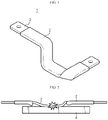
- the flexible bus bar 1 may be made into a desired shape by bending or twisting a necessary part, as shown in FIG. 1 , so the flexible bus bar 1 may be usefully used when connecting battery modules having different vibration axes or placed on complicated paths.
- the flexible bus bar 1 is easy to deform due to flexibility, but when fire occurs inside the battery pack, for example, the insulating tube 2 may be destroyed and sag by fire as shown in FIG. 2 so that a central portion of the metal bar 3 may contact a surrounding metal object 4 to cause a short circuit.
- the present disclosure is designed to solve the problems of the related art, and therefore the present disclosure is directed to providing a bus bar configured not to cause a short circuit since a metal bar does not directly contact a surrounding metal object even if an exterior sheath of the bus bar is destroyed by fire.
- a bus bar comprising: a metal bar made of an electrically conductive metal material; a bandage member configured to surround the metal bar except for both ends of the metal bar; and an insulating tube configured to surround the metal bar and the bandage member together.
- the bandage member may be provided in the form of a metal wire having a surface coated with a coating material having insulation and fire resistance.
- the coating material may be any one material selected from mica, silica and ceramic.
- the metal wire may be in the form of an annular metal band and provided in plural.
- the plurality of annular metal bands may be arranged at regular intervals along a longitudinal direction of the metal bar.
- the annular metal band may be compressively fixed to the metal bar in a state of surrounding a perimeter of the metal bar.
- a fire-resistive tape made of a fire-resistive material may be further attached to the surface of the metal bar surrounded by the bandage member.
- the metal wire may be wound on a perimeter of the metal bar in a helical structure along a longitudinal direction of the metal bar.
- the insulating tube may be made of a transparent silicon material.
- the metal bar may be formed by stacking metal plates with a thickness of 0.1 to 0.3mm to have flexibility.
- a battery pack comprising the bus bar described above.
- the bus bar according to the present disclosure may prevent a short circuit from occurring since the metal bar is configured not to directly contact a surrounding metal object even if an exterior sheath of the bus bar is destroyed by fire.
- the metal bar inside the exterior sheath is surrounded by a metal wire coated with a fire-resistant material, even if the exterior sheath is destroyed by fire when a fire occurs inside the battery pack, the metal wire remains. Thus, even if the metal bar sags, the surface of the metal bar does not directly contact a surrounding metal object, thereby preventing a short circuit.
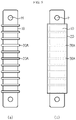
- FIG. 3 is a perspective view showing a bus bar 100 according to the first embodiment of the present disclosure
- FIG. 4 is a sectional view showing the bus bar 100, taken along the line I-I' of FIG. 3 .
- the bus bar 100 includes a metal bar 10 made of an electrically conductive metal material, an insulating tube 20 configured to cover the metal bar 10 not to be exposed to the outside except for both ends of the metal bar 10, and a bandage member 30A configured to surround the perimeter of the metal bar 10 inside the insulating tube 20.
- the thickness and width of the metal bar 10 may be determined according to the magnitude of conducted current, and its length may also be selected variously according to the installation location or installation conditions.
- the metal bar 10 may be formed by stacking several thin metal plates.
- the metal bar 10 may be prepared in a flexible structure that may be twisted or bent by stacking copper plates of approximately 0.1 to 0.3 mm and welding both ends thereof integrally.
- One end of both ends of the metal bar 10 may be connected to a (+) terminal of any one battery module, and the other end may be connected to a (-) terminal of another battery module.
- the terminals of the battery module may be configured in a bolt form that is inserted into a hole H formed at both ends of the metal bar 10 and then fastened with a nut to firmly fix the connection part.
- the insulating tube 20 is an exterior sheath of the metal bar 10, and may be made of silicone, rubber or a polymer material with elasticity, and may be provided on the metal bar 10 to cover the metal bar 10 and the bandage member 30A together.
- the insulating tube 20 of this embodiment may be made of transparent silicone.
- the insulating tube 20 made of transparent silicone has an advantage in that a binding state of the metal bar 10 and the bandage member 30A therein can be checked at any time.
- the bandage member 30A is a component that surrounds the perimeter of the metal bar 10 inside the insulating tube 20, and may be made of a metal wire whose surface is coated with a coating material 31 having electrical insulation and fire resistance.
- the bandage member 30A is made of a metal wire, the bandage member 30A is kept in the form of surrounding the metal bar 10. Therefore, even if the insulating tube 20 is destroyed by fire so that a middle portion of the metal bar 10 is exposed, the structure that the bandage member 30A still surrounds and supports the metal bar 10 is maintained as it is. Thus, even if the metal bar 10 sags toward a surrounding metal structure 4, it is possible to prevent the surface of the metal bar 10 from directly contacting the surrounding metal structure 4. At this time, even though the bandage member 30A comes into contact with the surrounding metal structure 4, since the bandage member 30A is coated with a material having electrical insulation and fire resistance, a current does not pass therethrough, so a short circuit does not occur.
- the coating material 31 having insulation and fire resistance at least one selected from mica, silica and ceramic may be employed.
- the metal wire included in the bandage member 30A may be provided in plural in the form of an annular metal band.
- the annular metal band is provided in plural, and the plurality of annular metal bands may be arranged at regular intervals along the longitudinal direction of the metal bar 10. If the annular metal bands are arranged at regular intervals along the longitudinal direction of the metal bar 10 as above, it may be easy to deform the shape of the metal bar 10 by bending the metal bar 10.
- the bandage member 30A is configured in the form of a long tube like the insulating tube 20, a most region of the metal bar 10 is held by the bandage member 30A, and thus it may be very difficult to bend or twist the metal bar 10.
- the bandage member 30A is manufactured using a plurality of metal bands that are arranged at regular intervals along the longitudinal direction of the metal bar 10, the region of the metal bar 10 not surrounded by the metal bands may be bent or twisted as desired.
- the annular metal bands are mounted to the metal bar 10 one by one in a fitting manner.
- annular metal bands are mounted to the metal bar 10 in this way so that the annular metal bands surrounds the perimeter of the metal bar 10, the annular metal bands are compressively fixed to the metal bar 10 using a clinching tool, thereby strengthening the bonding force between the metal bands and the metal bar 10.
- the insulating tube 20 is covered on the outer side of the metal bar 10 and the bandage member 30A to shield the metal bar 10 and the bandage member 30A except for both ends of the metal bar 10, thereby securing the electrical safety of the bus bar 100.
- the metal wire is interposed inside the insulating tube 20, so the thickness of the coating portion may be greater than that of the conventional bus bar 100.
- the bus bar 100 may be used to connect a plurality of battery modules in series, for example, in a pattern where one end of the bus bar 100 is fixedly connected to the (+) terminal of any one battery module and the other end of the bus bar 100 is fixedly connected to the (-) terminal of another battery module.
- the bus bar 100 when a fire occurs inside the battery pack containing a plurality of battery modules, even though the insulating tube 20 is completely melted down and destroyed by fire and the bus bar 100 sags, the metal bar 10 does not come into direct contact with the surrounding metal object.
- the bandage member 30A is not destroyed but remains bound to the metal bar 10. At this time, since the bandage member 30A supports the metal bar 10 so that the metal bar 10 does not contact the surrounding metal structure 4, it is possible to prevent a short circuit.
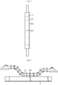
- FIG. 8 is a diagram showing a bus bar 200 according to the second embodiment of the present disclosure
- FIG. 9 is a diagram showing a bus bar 300 according to the third embodiment of the present disclosure.
- FIGS. 8 and 9 Next, other embodiments of the present disclosure will be described with reference to FIGS. 8 and 9 .
- the bus bar 200 according to the second embodiment of the present disclosure is different from the first embodiment in that the metal wire of the bandage member 30B has a helical structure or a coil spring structure, and the other features are the same.
- the metal wire of the helical structure forming the bandage member 30B may be provided to surround the perimeter of the metal bar 10 along the longitudinal direction of the metal bar 10.
- the electrical safety of the bus bar 200 may be secured by covering the insulating tube 20 on the outer side of the metal bar 10 and the bandage member 30B to shield the metal bar 10 except for both ends of the metal bar 10.
- the metal wire of the helical structure may have a diameter smaller than the width (D) of the metal bar 10.
- the metal bar 10 may be compressed by the bandage member 30B.
- the bandage member 30B may be firmly bound to the metal bar 10 without performing an additional process such as bonding, welding and compressing.
- a metal wire of a helical structure (or, a spring structure) made of pure metal is prepared. Then, the metal wire of a helical structure (or, a spring structure) is deformed into a straight line through a leveling operation. After that, ceramic is melted and injected to coat the surface of the metal wire.
- heat treatment may be used after glazing, or chemical vapor deposition (CVD), physical vapor deposition (PVD), or the like may also be used. Then, heat is applied to the ceramic-coated metal wire to transform into a metal wire type of a helical structure (or, a spring structure), thereby providing the bandage member 30B according to the second embodiment.
- the bus bar 300 according to the third embodiment of the present disclosure may be regarded as further including a fire-resistive tape 40, when compared with the former embodiments.
- the fire-resistive tape 40 is attached to the surface of the metal bar 10, and the metal bar 10 and the fire-resistive tape 40 are integrally wrapped with the bandage member 30A. Also, the insulating tube 20 is covered on the outer side of the bandage member 30A.
- the fire-resistive tape 40 is a tape with fire resistance for at least 600°C or higher and electrical insulation so as not to be destroyed by fire, and the fire-resistive tape 40 is a component responsible for protecting the metal bar 10 so that the metal bar 10 is not exposed even if the insulating tube 20 is destroyed by fire.
- the fire-resistive tape 40 a mica tape having excellent fire resistance and heat resistance may be used.
- any tape excellent in electrical insulation, fire resistance and heat resistance may also be used.
- the fire-resistive tape 40 is attached to the metal bar 10 before the metal bar 10 is covered by the insulating tube 20. At this time, the fire-resistive tape 40 having an adhesive substance on one surface is more preferred for easy attachment. However, since the fire-resistive tape 40 may be fixed to the metal bar 10 by using the bandage member 30A of the first embodiment or the bandage member 30B of the second embodiment, the fire-resistive tape 40 may also not have an adhesive substance on one surface thereof.
- the bus bar 300 of the third embodiment may be regarded as a safer bus bar 300 in terms of electrical insulation, compared to the former embodiments. That is, the ceramic coating is not easily peeled off due to its strong coating power, but the ceramic coating may be broken when subjected to a strong impact.
- the bus bar 100 of the first embodiment or the bus bar 200 of the second embodiment since the metal wire surrounds the metal bar 10, when a fire occurs, even if the metal bar 10 does not directly contact the surrounding metal structure 4, a current may flow in the metal wire, which may cause a short circuit.
- the bus bar 300 of the third embodiment even if the ceramic coating is broken, electrical insulation may still be secured by the fire-resistive tape 40, and accordingly, a short circuit does not occur in the above situation.
- the bus bar according to the present disclosure which has the configuration and operation as described above, even if the exterior sheath is destroyed by fire, it is possible to prevent the metal bar 10 from directly contacting the surrounding metal structure 4, and accordingly, a short circuit may not be caused. Therefore, it is possible to prevent a fire accident from spreading to a secondary fire.
- a battery pack may be configured to include at least one bus bar 100 described above.
- the battery pack may further include battery modules electrically connected by the bus bar 100, as well as various devices for controlling charging and discharging of the battery modules, such as a BMS, a current sensor, a fuse, and the like.
- the battery pack may be applied to vehicles such as an electric vehicle or a hybrid electric vehicle. Also, the battery pack may be applied to energy storage systems or other IT products.
Landscapes
- Chemical & Material Sciences (AREA)
- Chemical Kinetics & Catalysis (AREA)
- Electrochemistry (AREA)
- General Chemical & Material Sciences (AREA)
- Organic Chemistry (AREA)
- Inorganic Chemistry (AREA)
- Health & Medical Sciences (AREA)
- Public Health (AREA)
- Business, Economics & Management (AREA)
- Emergency Management (AREA)
- Connection Of Batteries Or Terminals (AREA)
- Battery Mounting, Suspending (AREA)
Applications Claiming Priority (2)
| Application Number | Priority Date | Filing Date | Title |
|---|---|---|---|
| KR1020200058253A KR102926964B1 (ko) | 2020-05-15 | 2020-05-15 | 화재 안전성이 우수한 버스바 |
| PCT/KR2021/003674 WO2021230489A1 (ko) | 2020-05-15 | 2021-03-24 | 화재 안전성이 우수한 버스바 |
Publications (2)
| Publication Number | Publication Date |
|---|---|
| EP4024601A1 true EP4024601A1 (de) | 2022-07-06 |
| EP4024601A4 EP4024601A4 (de) | 2023-01-25 |
Family
ID=78524849
Family Applications (1)
| Application Number | Title | Priority Date | Filing Date |
|---|---|---|---|
| EP21804617.5A Pending EP4024601A4 (de) | 2020-05-15 | 2021-03-24 | Stromschiene mit ausgezeichneter feuersicherheit |
Country Status (6)
| Country | Link |
|---|---|
| US (1) | US12183481B2 (de) |
| EP (1) | EP4024601A4 (de) |
| JP (1) | JP7375292B2 (de) |
| KR (1) | KR102926964B1 (de) |
| CN (1) | CN114424400A (de) |
| WO (1) | WO2021230489A1 (de) |
Cited By (6)
| Publication number | Priority date | Publication date | Assignee | Title |
|---|---|---|---|---|
| EP4213293A3 (de) * | 2022-01-14 | 2023-08-30 | SK On Co., Ltd. | Batteriepack |
| WO2023215492A3 (en) * | 2022-05-04 | 2023-12-07 | Aspen Aerogels, Inc. | Protection of electrical components in battery systems |
| EP4379947A4 (de) * | 2022-08-16 | 2025-03-12 | LG Energy Solution, Ltd. | Sammelschiene zwischen modulen mit feuerlöschflüssigkeit |
| EP4404370A4 (de) * | 2022-10-04 | 2025-03-12 | LG Energy Solution, Ltd. | Sammelschienenanordnung zur verhinderung von schäden durch auftreten von feuer und batteriepack damit |
| EP4550551A4 (de) * | 2022-07-08 | 2025-12-17 | Lg Energy Solution Ltd | Batteriemodul mit verbesserter entlüftungsstruktur |
| EP4648208A4 (de) * | 2023-03-21 | 2026-04-15 | Lg Energy Solution Ltd | Sammelschiene zwischen modulen |
Families Citing this family (34)
| Publication number | Priority date | Publication date | Assignee | Title |
|---|---|---|---|---|
| US20230036275A1 (en) * | 2021-07-29 | 2023-02-02 | Ford Global Technologies, Llc | Bus bar configurations for connecting battery pack components |
| KR20230118390A (ko) * | 2022-02-04 | 2023-08-11 | 현대자동차주식회사 | 차량의 배터리시스템 |
| US12482892B2 (en) * | 2022-02-08 | 2025-11-25 | Ford Global Technologies, Llc | Thermal barrier for busbar of traction battery |
| WO2023224125A1 (ja) * | 2022-05-19 | 2023-11-23 | イビデン株式会社 | バスバー及びその製造方法、並びに蓄電装置 |
| JP7832051B2 (ja) * | 2022-05-19 | 2026-03-17 | イビデン株式会社 | バスバー及び蓄電装置 |
| JP2023171187A (ja) * | 2022-05-19 | 2023-12-01 | イビデン株式会社 | バスバー及びその製造方法、並びに蓄電装置 |
| JP7832052B2 (ja) * | 2022-05-19 | 2026-03-17 | イビデン株式会社 | バスバー及び蓄電装置 |
| JP2024018702A (ja) * | 2022-07-29 | 2024-02-08 | イビデン株式会社 | バスバー及びその製造方法、並びに蓄電装置 |
| JP7518133B2 (ja) * | 2022-07-29 | 2024-07-17 | イビデン株式会社 | バスバー及びその製造方法、並びに蓄電装置 |
| JP2024023064A (ja) * | 2022-08-08 | 2024-02-21 | イビデン株式会社 | バスバー及びその製造方法、並びに蓄電装置 |
| KR20240033312A (ko) | 2022-09-05 | 2024-03-12 | 주식회사 엘지에너지솔루션 | 절연층을 포함하는 인터 모듈 버스바 및 이를 포함하는 전지팩 |
| EP4443639A4 (de) | 2022-09-08 | 2026-02-11 | Lg Energy Solution Ltd | Sammelschiene mit verbesserter flammbeständigkeit und batteriepack damit |
| KR102872698B1 (ko) | 2022-09-08 | 2025-10-20 | 주식회사 엘지에너지솔루션 | 내화염성이 향상된 버스바 및 이를 포함하는 전지팩 |
| KR20240047835A (ko) | 2022-10-05 | 2024-04-12 | 주식회사 엘지에너지솔루션 | 방화벽을 포함하는 버스바 어셈블리 및 이를 포함하는 전지팩 |
| KR20240058547A (ko) * | 2022-10-26 | 2024-05-03 | 주식회사 엘지에너지솔루션 | 내화버스바 및 이를 구비한 배터리 팩 |
| CN118280635A (zh) * | 2022-12-30 | 2024-07-02 | 比亚迪股份有限公司 | 导电杆、导电杆组件、电气系统及车辆 |
| KR20240112015A (ko) * | 2023-01-11 | 2024-07-18 | 주식회사 엘지에너지솔루션 | 버스바 조립체 및 이를 포함하는 전지팩 |
| KR20240112014A (ko) * | 2023-01-11 | 2024-07-18 | 주식회사 엘지에너지솔루션 | 버스바 조립체 및 이를 포함하는 전지팩 |
| KR20240119411A (ko) * | 2023-01-30 | 2024-08-06 | 주식회사 엘지에너지솔루션 | 버스바 조립체 및 이를 포함하는 전지팩 |
| KR20240119413A (ko) * | 2023-01-30 | 2024-08-06 | 주식회사 엘지에너지솔루션 | 버스바 조립체 및 이를 포함하는 전지팩 |
| JP2024122742A (ja) * | 2023-02-28 | 2024-09-09 | イビデン株式会社 | バスバー及びその製造方法、並びに蓄電装置 |
| JP2024122741A (ja) * | 2023-02-28 | 2024-09-09 | イビデン株式会社 | バスバー及びその製造方法、並びに蓄電装置 |
| JP2024132035A (ja) * | 2023-03-17 | 2024-09-30 | サンコール株式会社 | フレキシブルバスバー |
| KR20240142976A (ko) * | 2023-03-23 | 2024-10-02 | 주식회사 엘지에너지솔루션 | 내화버스바 및 이를 구비한 배터리 팩 |
| JP2024155552A (ja) * | 2023-04-21 | 2024-10-31 | イビデン株式会社 | バスバー及びその製造方法、並びに蓄電装置 |
| WO2025004391A1 (ja) * | 2023-06-29 | 2025-01-02 | Swcc株式会社 | 車載用バスバーおよびその製造方法 |
| KR20250003084A (ko) * | 2023-06-30 | 2025-01-07 | 주식회사 엘지에너지솔루션 | 전기접속용 와이어 및 이를 이용하여 전기적인 연결을 형성하는 전지모듈 |
| KR102627004B1 (ko) * | 2023-07-03 | 2024-01-23 | 덕부화학 주식회사 | 전기 자동차용 배터리팩의 완충 버스바 |
| KR20250006460A (ko) * | 2023-07-04 | 2025-01-13 | 주식회사 엘지에너지솔루션 | 버스바 조립체 및 이를 포함하는 전지 팩 |
| KR20250022486A (ko) * | 2023-08-08 | 2025-02-17 | 주식회사 엘지에너지솔루션 | 버스바 조립체 및 이를 포함하는 전지 팩 |
| KR20250024338A (ko) * | 2023-08-11 | 2025-02-18 | 주식회사 엘지에너지솔루션 | 버스바 조립체 및 이를 포함하는 전지 팩 |
| JP2025117195A (ja) * | 2024-01-30 | 2025-08-12 | Swcc株式会社 | バスバー |
| KR102721398B1 (ko) * | 2024-03-22 | 2024-10-24 | 한국그린전력(주) | 위크튜브 버스바 |
| KR20250164414A (ko) * | 2024-05-16 | 2025-11-25 | 주식회사 엘지에너지솔루션 | 버스바 조립체 및 이를 포함하는 전지 팩 |
Family Cites Families (30)
| Publication number | Priority date | Publication date | Assignee | Title |
|---|---|---|---|---|
| US1946190A (en) * | 1930-09-24 | 1934-02-06 | Carl P Brodhun | Cable |
| US3649744A (en) * | 1970-06-19 | 1972-03-14 | Coleman Cable & Wire Co | Service entrance cable with preformed fiberglass tape |
| US3867758A (en) * | 1973-07-06 | 1975-02-25 | Anaconda Co | Method of making glass insulated electrical coils |
| US3842193A (en) * | 1973-07-06 | 1974-10-15 | Anaconda Co | Glass insulated magnet wire |
| JPS5264397U (de) * | 1975-11-08 | 1977-05-12 | ||
| JPH06140020A (ja) * | 1992-10-22 | 1994-05-20 | Yazaki Corp | バッテリー接続端子 |
| JP4238787B2 (ja) | 2004-06-17 | 2009-03-18 | 住友電装株式会社 | シールドコネクタ |
| JP2006187122A (ja) * | 2004-12-27 | 2006-07-13 | Auto Network Gijutsu Kenkyusho:Kk | 回路構成体 |
| KR20070054403A (ko) | 2005-11-23 | 2007-05-29 | 현대중공업 주식회사 | 가스절연 차단기의 부스바용 절연튜브 |
| KR100981924B1 (ko) | 2009-11-20 | 2010-09-13 | (주)에코세라 | 티탄산칼륨섬유를 함유한 고내열 전기절연 코팅제 및 그의 제조 방법 |
| KR101141379B1 (ko) | 2010-07-06 | 2012-05-03 | 삼성전기주식회사 | 에너지 저장 모듈 |
| JP2012182047A (ja) * | 2011-03-02 | 2012-09-20 | Auto Network Gijutsu Kenkyusho:Kk | バスバーセット及びその製造方法 |
| JP2012182043A (ja) * | 2011-03-02 | 2012-09-20 | Auto Network Gijutsu Kenkyusho:Kk | バスバー |
| JP6056238B2 (ja) | 2011-12-12 | 2017-01-11 | 株式会社アドヴィックス | 回路基板と電気部品との電気接続構造 |
| KR101579124B1 (ko) | 2013-12-30 | 2015-12-21 | 두산중공업 주식회사 | 고온 연료전지용 앤드플레이트 |
| KR20150101154A (ko) | 2014-02-26 | 2015-09-03 | 엘에스전선 주식회사 | 플렉서블 버스바 |
| KR20160049260A (ko) * | 2014-10-27 | 2016-05-09 | 엘에스전선 주식회사 | 플렉서블 버스바 |
| CN106450988B (zh) * | 2015-08-06 | 2020-03-31 | 富士康(昆山)电脑接插件有限公司 | 线缆连接器组件及其制造方法 |
| KR20170021697A (ko) * | 2015-08-18 | 2017-02-28 | 한국단자공업 주식회사 | 고전압용 버스바조립체 |
| KR101684904B1 (ko) | 2015-10-13 | 2016-12-12 | 한국기계연구원 | 저항재료가 코팅된 형상기억합금 스프링 및 그 제작방법 |
| US11310948B2 (en) * | 2016-03-11 | 2022-04-19 | Flex-Cable | Bendable shielded bus bar |
| KR102680702B1 (ko) * | 2016-06-14 | 2024-07-03 | 삼성전자주식회사 | 스트랩 및 이를 포함하는 전자 장치 |
| CN206421843U (zh) * | 2017-01-22 | 2017-08-18 | 福建东电电力设备有限公司 | 一种中心阻燃式半绝缘母线 |
| JP2018181780A (ja) * | 2017-04-21 | 2018-11-15 | 矢崎総業株式会社 | 積層バスバおよび電池モジュール |
| JP6618504B2 (ja) * | 2017-04-28 | 2019-12-11 | 矢崎総業株式会社 | バスバー及びバスバーの製造方法 |
| KR20190009120A (ko) * | 2017-07-18 | 2019-01-28 | 한국단자공업 주식회사 | 버스바조립체 및 그 제조방법 |
| CN109285633B (zh) * | 2017-07-21 | 2021-08-10 | 矢崎(中国)投资有限公司 | 利用金属芯线制造汇流排的方法以及汇流排 |
| JP7006051B2 (ja) * | 2017-09-08 | 2022-02-10 | 日産自動車株式会社 | 電池パック、導電部材および保護部材 |
| CN208938704U (zh) * | 2018-11-15 | 2019-06-04 | 济南富利通电气技术有限公司 | 一种包绕式耐火型管型母线 |
| KR20200058253A (ko) | 2018-11-19 | 2020-05-27 | 강기석 | 위치조절이 구비된 돋보기 펜 |
-
2020
- 2020-05-15 KR KR1020200058253A patent/KR102926964B1/ko active Active
-
2021
- 2021-03-24 US US17/762,938 patent/US12183481B2/en active Active
- 2021-03-24 EP EP21804617.5A patent/EP4024601A4/de active Pending
- 2021-03-24 JP JP2022513378A patent/JP7375292B2/ja active Active
- 2021-03-24 WO PCT/KR2021/003674 patent/WO2021230489A1/ko not_active Ceased
- 2021-03-24 CN CN202180005433.4A patent/CN114424400A/zh active Pending
Cited By (6)
| Publication number | Priority date | Publication date | Assignee | Title |
|---|---|---|---|---|
| EP4213293A3 (de) * | 2022-01-14 | 2023-08-30 | SK On Co., Ltd. | Batteriepack |
| WO2023215492A3 (en) * | 2022-05-04 | 2023-12-07 | Aspen Aerogels, Inc. | Protection of electrical components in battery systems |
| EP4550551A4 (de) * | 2022-07-08 | 2025-12-17 | Lg Energy Solution Ltd | Batteriemodul mit verbesserter entlüftungsstruktur |
| EP4379947A4 (de) * | 2022-08-16 | 2025-03-12 | LG Energy Solution, Ltd. | Sammelschiene zwischen modulen mit feuerlöschflüssigkeit |
| EP4404370A4 (de) * | 2022-10-04 | 2025-03-12 | LG Energy Solution, Ltd. | Sammelschienenanordnung zur verhinderung von schäden durch auftreten von feuer und batteriepack damit |
| EP4648208A4 (de) * | 2023-03-21 | 2026-04-15 | Lg Energy Solution Ltd | Sammelschiene zwischen modulen |
Also Published As
| Publication number | Publication date |
|---|---|
| KR102926964B1 (ko) | 2026-02-11 |
| JP7375292B2 (ja) | 2023-11-08 |
| EP4024601A4 (de) | 2023-01-25 |
| JP2022545548A (ja) | 2022-10-27 |
| US20220415537A1 (en) | 2022-12-29 |
| KR20210141095A (ko) | 2021-11-23 |
| CN114424400A (zh) | 2022-04-29 |
| US12183481B2 (en) | 2024-12-31 |
| WO2021230489A1 (ko) | 2021-11-18 |
Similar Documents
| Publication | Publication Date | Title |
|---|---|---|
| US12183481B2 (en) | Bus bar with safety against fire | |
| KR102946350B1 (ko) | 화재 안전성이 우수한 버스바 | |
| US12135002B2 (en) | Battery device for a battery jump starting device | |
| EP2192601B1 (de) | Kabelbaum und verfahren zu seiner herstellung | |
| JP5254246B2 (ja) | 生産性及び構造的安定性が優れたバッテリーパック | |
| US9105912B2 (en) | Boltless battery cell connection | |
| EP2389699B1 (de) | Einzelzelle und strombatteriepack damit | |
| US20120100761A1 (en) | Battery Cell Connector | |
| EP2876651B1 (de) | Kabelbaum | |
| US9490051B2 (en) | Method for producing wire harness | |
| EP4178025B1 (de) | Ffc-sammelschiene | |
| JP5825991B2 (ja) | 蓄電池用の電線配索構造 | |
| EP3641019A2 (de) | Batterieanordnung | |
| KR102815964B1 (ko) | 부분 인서트 사출을 적용한 플랙서블 버스바 | |
| WO2016010150A1 (ja) | バスバーモジュール及びバスバーモジュールの製造方法 | |
| EP3641045B1 (de) | Kabelartige batterie | |
| EP2738775B1 (de) | Hochspannungsleitungspfad und kabelbaum | |
| EP3951804B1 (de) | Ffc-kabelanordnung | |
| JP2019091668A (ja) | バスバーモジュール、及びワイヤーハーネス | |
| KR102824547B1 (ko) | Ffc 케이블 조립체 | |
| US20130196217A1 (en) | Battery, Battery System and Method for Connecting a Plurality of Batteries | |
| WO2018175599A1 (en) | Flexible circuits for electrical harnesses | |
| JP3123120U (ja) | リード線付きヒューズ | |
| JP2024126179A (ja) | 電池装置およびその製造方法 |
Legal Events
| Date | Code | Title | Description |
|---|---|---|---|
| STAA | Information on the status of an ep patent application or granted ep patent |
Free format text: STATUS: THE INTERNATIONAL PUBLICATION HAS BEEN MADE |
|
| PUAI | Public reference made under article 153(3) epc to a published international application that has entered the european phase |
Free format text: ORIGINAL CODE: 0009012 |
|
| STAA | Information on the status of an ep patent application or granted ep patent |
Free format text: STATUS: REQUEST FOR EXAMINATION WAS MADE |
|
| 17P | Request for examination filed |
Effective date: 20220331 |
|
| AK | Designated contracting states |
Kind code of ref document: A1 Designated state(s): AL AT BE BG CH CY CZ DE DK EE ES FI FR GB GR HR HU IE IS IT LI LT LU LV MC MK MT NL NO PL PT RO RS SE SI SK SM TR |
|
| A4 | Supplementary search report drawn up and despatched |
Effective date: 20221222 |
|
| RIC1 | Information provided on ipc code assigned before grant |
Ipc: H01B 7/00 20060101ALI20221216BHEP Ipc: C09J 7/30 20180101ALI20221216BHEP Ipc: C09J 1/00 20060101ALI20221216BHEP Ipc: H01R 13/527 20060101ALI20221216BHEP Ipc: H01R 4/34 20060101ALI20221216BHEP Ipc: H01M 50/593 20210101ALI20221216BHEP Ipc: H01M 50/597 20210101ALI20221216BHEP Ipc: H01M 50/526 20210101ALI20221216BHEP Ipc: H01M 50/522 20210101ALI20221216BHEP Ipc: H01M 50/505 20210101ALI20221216BHEP Ipc: H01M 50/503 20210101ALI20221216BHEP Ipc: H01M 50/502 20210101ALI20221216BHEP Ipc: H01M 50/572 20210101AFI20221216BHEP |
|
| DAV | Request for validation of the european patent (deleted) | ||
| DAX | Request for extension of the european patent (deleted) |