EP4012803A1 - Negatives elektrodenmaterial, elektrochemische vorrichtung damit und elektronische vorrichtung - Google Patents
Negatives elektrodenmaterial, elektrochemische vorrichtung damit und elektronische vorrichtung Download PDFInfo
- Publication number
- EP4012803A1 EP4012803A1 EP19952437.2A EP19952437A EP4012803A1 EP 4012803 A1 EP4012803 A1 EP 4012803A1 EP 19952437 A EP19952437 A EP 19952437A EP 4012803 A1 EP4012803 A1 EP 4012803A1
- Authority
- EP
- European Patent Office
- Prior art keywords
- anode material
- anode
- layer
- material according
- carbon
- Prior art date
- Legal status (The legal status is an assumption and is not a legal conclusion. Google has not performed a legal analysis and makes no representation as to the accuracy of the status listed.)
- Granted
Links
Images


Classifications
-
- H—ELECTRICITY
- H01—ELECTRIC ELEMENTS
- H01M—PROCESSES OR MEANS, e.g. BATTERIES, FOR THE DIRECT CONVERSION OF CHEMICAL ENERGY INTO ELECTRICAL ENERGY
- H01M4/00—Electrodes
- H01M4/02—Electrodes composed of, or comprising, active material
- H01M4/13—Electrodes for accumulators with non-aqueous electrolyte, e.g. for lithium-accumulators; Processes of manufacture thereof
- H01M4/134—Electrodes based on metals, Si or alloys
-
- H—ELECTRICITY
- H01—ELECTRIC ELEMENTS
- H01M—PROCESSES OR MEANS, e.g. BATTERIES, FOR THE DIRECT CONVERSION OF CHEMICAL ENERGY INTO ELECTRICAL ENERGY
- H01M4/00—Electrodes
- H01M4/02—Electrodes composed of, or comprising, active material
- H01M4/36—Selection of substances as active materials, active masses, active liquids
- H01M4/38—Selection of substances as active materials, active masses, active liquids of elements or alloys
- H01M4/386—Silicon or alloys based on silicon
-
- H—ELECTRICITY
- H01—ELECTRIC ELEMENTS
- H01M—PROCESSES OR MEANS, e.g. BATTERIES, FOR THE DIRECT CONVERSION OF CHEMICAL ENERGY INTO ELECTRICAL ENERGY
- H01M4/00—Electrodes
- H01M4/02—Electrodes composed of, or comprising, active material
- H01M4/36—Selection of substances as active materials, active masses, active liquids
- H01M4/362—Composites
- H01M4/366—Composites as layered products
-
- H—ELECTRICITY
- H01—ELECTRIC ELEMENTS
- H01M—PROCESSES OR MEANS, e.g. BATTERIES, FOR THE DIRECT CONVERSION OF CHEMICAL ENERGY INTO ELECTRICAL ENERGY
- H01M4/00—Electrodes
- H01M4/02—Electrodes composed of, or comprising, active material
- H01M4/36—Selection of substances as active materials, active masses, active liquids
- H01M4/48—Selection of substances as active materials, active masses, active liquids of inorganic oxides or hydroxides
- H01M4/483—Selection of substances as active materials, active masses, active liquids of inorganic oxides or hydroxides for non-aqueous cells
-
- H—ELECTRICITY
- H01—ELECTRIC ELEMENTS
- H01M—PROCESSES OR MEANS, e.g. BATTERIES, FOR THE DIRECT CONVERSION OF CHEMICAL ENERGY INTO ELECTRICAL ENERGY
- H01M4/00—Electrodes
- H01M4/02—Electrodes composed of, or comprising, active material
- H01M4/62—Selection of inactive substances as ingredients for active masses, e.g. binders, fillers
-
- H—ELECTRICITY
- H01—ELECTRIC ELEMENTS
- H01M—PROCESSES OR MEANS, e.g. BATTERIES, FOR THE DIRECT CONVERSION OF CHEMICAL ENERGY INTO ELECTRICAL ENERGY
- H01M4/00—Electrodes
- H01M4/02—Electrodes composed of, or comprising, active material
- H01M4/62—Selection of inactive substances as ingredients for active masses, e.g. binders, fillers
- H01M4/621—Binders
- H01M4/622—Binders being polymers
-
- H—ELECTRICITY
- H01—ELECTRIC ELEMENTS
- H01M—PROCESSES OR MEANS, e.g. BATTERIES, FOR THE DIRECT CONVERSION OF CHEMICAL ENERGY INTO ELECTRICAL ENERGY
- H01M4/00—Electrodes
- H01M4/02—Electrodes composed of, or comprising, active material
- H01M4/62—Selection of inactive substances as ingredients for active masses, e.g. binders, fillers
- H01M4/624—Electric conductive fillers
- H01M4/625—Carbon or graphite
-
- H—ELECTRICITY
- H01—ELECTRIC ELEMENTS
- H01M—PROCESSES OR MEANS, e.g. BATTERIES, FOR THE DIRECT CONVERSION OF CHEMICAL ENERGY INTO ELECTRICAL ENERGY
- H01M10/00—Secondary cells; Manufacture thereof
- H01M10/05—Accumulators with non-aqueous electrolyte
- H01M10/052—Li-accumulators
- H01M10/0525—Rocking-chair batteries, i.e. batteries with lithium insertion or intercalation in both electrodes; Lithium-ion batteries
-
- H—ELECTRICITY
- H01—ELECTRIC ELEMENTS
- H01M—PROCESSES OR MEANS, e.g. BATTERIES, FOR THE DIRECT CONVERSION OF CHEMICAL ENERGY INTO ELECTRICAL ENERGY
- H01M4/00—Electrodes
- H01M4/02—Electrodes composed of, or comprising, active material
- H01M2004/021—Physical characteristics, e.g. porosity, surface area
-
- H—ELECTRICITY
- H01—ELECTRIC ELEMENTS
- H01M—PROCESSES OR MEANS, e.g. BATTERIES, FOR THE DIRECT CONVERSION OF CHEMICAL ENERGY INTO ELECTRICAL ENERGY
- H01M4/00—Electrodes
- H01M4/02—Electrodes composed of, or comprising, active material
- H01M2004/026—Electrodes composed of, or comprising, active material characterised by the polarity
- H01M2004/027—Negative electrodes
-
- H—ELECTRICITY
- H01—ELECTRIC ELEMENTS
- H01M—PROCESSES OR MEANS, e.g. BATTERIES, FOR THE DIRECT CONVERSION OF CHEMICAL ENERGY INTO ELECTRICAL ENERGY
- H01M4/00—Electrodes
- H01M4/02—Electrodes composed of, or comprising, active material
- H01M4/62—Selection of inactive substances as ingredients for active masses, e.g. binders, fillers
- H01M4/621—Binders
- H01M4/622—Binders being polymers
- H01M4/623—Binders being polymers fluorinated polymers
-
- Y—GENERAL TAGGING OF NEW TECHNOLOGICAL DEVELOPMENTS; GENERAL TAGGING OF CROSS-SECTIONAL TECHNOLOGIES SPANNING OVER SEVERAL SECTIONS OF THE IPC; TECHNICAL SUBJECTS COVERED BY FORMER USPC CROSS-REFERENCE ART COLLECTIONS [XRACs] AND DIGESTS
- Y02—TECHNOLOGIES OR APPLICATIONS FOR MITIGATION OR ADAPTATION AGAINST CLIMATE CHANGE
- Y02E—REDUCTION OF GREENHOUSE GAS [GHG] EMISSIONS, RELATED TO ENERGY GENERATION, TRANSMISSION OR DISTRIBUTION
- Y02E60/00—Enabling technologies; Technologies with a potential or indirect contribution to GHG emissions mitigation
- Y02E60/10—Energy storage using batteries
Definitions
- the present application relates to the technical field of energy storage, and particularly to an anode material, an electrochemical device and an electronic device comprising the anode material, particularly, lithium ion batteries.
- a battery is not only required to be light in weight, but is also required to have high capacity and a relatively long service life.
- Lithium-ion batteries have occupied the leading position in the market due to their outstanding advantages, such as high energy density, excellent safety, no memory effect, and long service life.
- Embodiments of the present application provide an anode material and a method for preparing the anode material, to solve at least one of the problems existing in related art to some extent.
- An embodiment of the present application also provides an anode using the anode material, an electrochemical device, and an electronic device.
- the present application provides an anode material, which comprises a silicon composite substrate, the D V 50 of the silicon composite substrate is from about 2.5 ⁇ m to 15 ⁇ m, and the particle size distribution of the silicon composite substrate meets: about 0.1 ⁇ Dn10/Dv50 ⁇ about 0.6.
- the present application provides an anode, which comprises an anode material according to an embodiment of the present application.
- the present application provides an electrochemical device, which comprises an anode according to an embodiment of the present application.
- the present application provides an electronic device, which comprises an electrochemical device according to an embodiment of the present application.
- the anode active material of the present application has good cycle performance, and the lithium ion battery prepared with the anode active material has good rate performance and lower swelling rate.
- the terms "about” is used for describing and explaining a small variation.
- the term may refer to an example in which the event or circumstance occurs precisely, and an example in which the event or circumstance occurs approximately.
- the term may refer to a range of variation less than or equal to ⁇ 10% of the stated value, such as less than or equal to ⁇ 5%, less than or equal to ⁇ 4%, less than or equal to ⁇ 3%, less than or equal to ⁇ 2%, less than or equal to ⁇ 1%, less than or equal to ⁇ 0.5%, less than or equal to ⁇ 0.1%, or less than or equal to ⁇ 0.05%.
- Dv50 is the particle size corresponding to a cumulative volume percentage of the anode active material that is50%, and the unit is ⁇ m.
- Dn10 is the particle size corresponding to a cumulative number percentage of the anode active material that is 10%, and the unit is ⁇ m.
- the silicon composite comprises elemental silicon, a silicon compound, a mixture of elemental silicon and a silicon compound, or a mixture of various silicides.
- a list of items connected by the term “one of” or the like means any one of the listed items. For example, if items A and B are listed, the phrase “one of A and B” means only A or only B. In another example, if items A, B, and C are listed, then the phrase "one of A, B, and C" means only A; only B; or only C.
- Item A may include a single or multiple elements.
- Item B may include a single or multiple elements.
- Item C may include a single or multiple elements.
- a list of items connected by the term "at least one of” or the like means any combination of the listed items. For example, if items A and B are listed, the phrase "at least one of A and B" means only A; only B; or A and B. In another example, if items A, B, and C are listed, then the phrase "at least one of A, B, and C" means only A; only B; only C; A and B (excluding C); A and C (excluding B); B and C (excluding A); or A, B, and C.
- Item A may include a single or multiple elements.
- Item B may include a single or multiple elements.
- Item C may include a single or multiple elements.
- An embodiment of the present application provides an anode material, which comprises a silicon composite substrate, the D V 50 of the silicon composite substrate is from 2.5 ⁇ m to 15 ⁇ m, and the particle size distribution of the silicon composite substrate meets: 0.1 ⁇ Dn10/Dv50 ⁇ 0.6.
- the D V 50 of the silicon composite substrate is from about 2.5 ⁇ m to 15 ⁇ m. In some embodiments, the Dv50 of the silicon composite substrate is from about 2.5 ⁇ m to 10 ⁇ m. In some embodiments, the Dv50 of the silicon composite substrate is from about 3 ⁇ m to 9 ⁇ m. In some embodiments, the Dv50 of the silicon composite substrate is from about 4 ⁇ m to 7 ⁇ m.
- the silicon composite substrate comprises a silicon-containing substance.
- the silicon-containing substance in the silicon composite substrate can form a composite with one or more of other substances than the silicon-containing substance in the anode material.
- the silicon composite substrate comprises particles that can intercalate and deintercalate lithium ions.
- the silicon composite substrate comprises SiO x , wherein about 0.6 ⁇ x ⁇ about 1.5.
- the silicon composite substrate comprises nano-Si crystalline grains, SiO, SiO 2 , or any combination thereof.
- the particle size of the nano-Si crystalline grains is less than about 100 nm. In some embodiments, the particle size of the nano-Si crystalline grains is less than about 50 nm. In some embodiments, the particle size of the nano-Si crystalline grains is less than about 20 nm. In some embodiments, the particle size of the nano-Si crystalline grains is less than about 5 nm. In some embodiments, the particle size of the nano-Si crystalline grains is less than about 2 nm. In some embodiments, the particle size of the nano-Si crystalline grains is less than about 0.5 nm.
- the anode material further comprises an oxide MeO y layer coating at least a portion of the silicon composite substrate, wherein Me includes at least one of Al, Si, Ti, Mn, V, Cr, Co or Zr, and y is about 0.5-3; and wherein the oxide MeO y layer comprises a carbon material.
- the oxide MeO y includes Al 2 O 3 , SiO 2 , TiO 2 , Mn 2 O 3 , MnO 2 , CrO 3 , Cr 2 O 3 , CrO 2 , V 2 O 5 , VO, CoO, Co 2 O 3 , Co 3 O 4 , ZrO 2 or any combination thereof.
- the carbon material in the oxide MeO y layer includes amorphous carbon, carbon nanotubes, carbon nanoparticles, carbon fibers, graphene, or any combination thereof.
- the amorphous carbon is a carbon material obtained by sintering a carbon precursor at high temperature.
- the carbon precursor includes polyvinylpyrrolidone, sodium carboxymethyl cellulose, polyvinyl alcohol, polypropylene, phenolic resin, polyester resin, polyamide resin, epoxy resin, polyurethane, polyacrylic resin or any combination thereof.
- the thickness of the oxide MeO y layer is about 1 nm to 1000 nm. In some embodiments, the thickness of the oxide MeO y layer is about 10 nm to 900 nm. In some embodiments, the thickness of the oxide MeO y layer is about 20 nm to 800 nm. In some embodiments, the thickness of the oxide MeO y layer is about 1 nm to 20 nm. In some embodiments, the thickness of the oxide MeO y layer is about 2 nm, about 5 nm, about 10 nm, about 15 nm, about 20 nm, or about 50 nm.
- the weight percentage of the Me element is about 0.01 wt% to 1 wt%. In some embodiments, based on the total weight of the anode material, the weight percentage of the Me element is about 0.02 wt% to 1 wt%. In some embodiments, based on the total weight of the anode material, the weight percentage of the Me element is about 0.03 wt% to 0.9 wt%.
- the weight percentage of the Me element is about 0.05 wt%, about 0.1 wt%, about 0.2 wt%, about 0.3 wt%, about 0.4 wt%, about 0.5 wt%, about 0.6 wt%, about 0.7 wt% or about 0.8 wt%.
- the weight percentage of the carbon material in the oxide MeO y layer is about 0.05 wt% to 1 wt%. In some embodiments, based on the total weight of the anode material, the weight percentage of the carbon material in the oxide MeO y layer is about 0.1 wt% to 0.8 wt%. In some embodiments, based on the total weight of the anode material, the weight percentage of the carbon material in the oxide MeO y layer is about 0.2 wt% to 0.7 wt%.
- the weight percentage of the carbon material in the oxide MeO y layer is about 0.3 wt%, about 0.4 wt%, about 0.5 wt%, about 0.6 wt%, about 0.7 wt% or about 0.8 wt%.
- the anode material further comprises a polymer layer that coats at least a portion of the oxide MeO y layer, wherein the polymer layer comprises a carbon material.
- the polymer layer comprises polyvinylidene fluoride and its derivatives, carboxymethyl cellulose and its derivatives, sodium carboxymethyl cellulose and its derivatives, polyvinylpyrrolidone and its derivatives, polyacrylic acid and its derivatives, polystyrene-butadiene rubber, polyacrylamide, polyimide, polyamideimide or any combination thereof.
- the carbon material in the polymer layer includes carbon nanotubes, carbon nanoparticles, carbon fibers, graphene, or any combination thereof.
- the weight percentage of the polymer layer is about 0.1 wt% to 10 wt%. In some embodiments, based on the total weight of the anode material, the weight percentage of the polymer layer is about 0.2 wt% to 8 wt%. In some embodiments, based on the total weight of the anode material, the weight percentage of the polymer layer is about 0.3 wt% to 7 wt%. In some embodiments, based on the total weight of the anode material, the weight percentage of the polymer layer is about 1 wt%, about 1.5 wt%, about 2 wt%, about 4 wt%, about 5 wt% or about 6 wt%.
- the thickness of the polymer layer is about 2 nm to 100 nm. In some embodiments, the thickness of the polymer layer is about 10 nm to 90 nm. In some embodiments, the thickness of the polymer layer is about 15 nm to 80 nm. In some embodiments, the thickness of the polymer layer is about 5 nm, about 20 nm, about 25 nm, about 45 nm, about 55 nm or about 75 nm.
- the anode material has a specific surface area of about 1 m 2 /g to 50 m 2 /g. In some embodiments, the anode material has a specific surface area of about 1 m 2 /g to 30 m 2 /g. In some embodiments, the anode material has a specific surface area of about 1 m 2 /g to 10 m 2 /g. In some embodiments, the anode material has a specific surface area of about 1 m 2 /g, about 5 m 2 /g, or about 10 m 2 /g.
- the highest intensity at 2 ⁇ within the range of about 27.0° to 30.0° is I 2
- the highest intensity at 2 ⁇ within the range of about 20.0° to 22.0° is I 1
- the highest intensity at 2 ⁇ of about 28.4° is I 2
- the highest intensity at 2 ⁇ of about 21.0° is I 1
- I 2 /I 1 is 0.2, 0.4 or 0.5.
- An embodiment of the present application provides a method for preparing any of the anode material as described above, the method comprises: grading silicon oxide SiO x to obtain an anode material having a particle size distribution meeting: 0.1 ⁇ Dn10/Dv50 ⁇ 0.6, where 0.6 ⁇ x ⁇ 1.5.
- the grading includes air flow classification.
- the method further comprises a step of coating an oxide MeO y layer, comprising:
- the oxide precursor MeT n includes isopropyl titanate, aluminum isopropoxide, or a combination thereof.
- the carbon material includes amorphous carbon, carbon nanotubes, carbon nanoparticles, carbon fibers, graphene, or any combination thereof.
- the amorphous carbon is a carbon material obtained by sintering a carbon precursor at high temperature.
- the carbon precursor includes polyvinylpyrrolidone, sodium carboxymethyl cellulose, polyvinyl alcohol, polypropylene, phenolic resin, polyester resin, polyamide resin, epoxy resin, polyurethane, polyacrylic resin or any combination thereof.
- the sintering temperature is about 250 °C to 800°C. In some embodiments, the sintering temperature is about 300 °C to 700°C. In some embodiments, the sintering temperature is about 400, about 500°C or about 600°C.
- the sintering time is about 1 hr to 18 hr. In some embodiments, the sintering time is about 1 hr to 16 h. In some embodiments, the sintering time is about 1 hr to 12 hr. In some embodiments, the sintering time is about 1.5 hr to 6 hr. In some embodiments, the sintering time is about 1.5 hr, about 2.5 hr, about 3.5 hr, about 5 hr or about 6 hr.
- the organic solvent includes at least one of ethanol, methanol, n-hexane, N,N-dimethylformamide, pyrrolidone, acetone, toluene, isopropanol or n-propanol. In some embodiments, the organic solvent is ethanol.
- the halogen includes F, Cl, Br, or a combination thereof.
- the sintering is carried out under an inert gas atmosphere.
- the inert gas includes nitrogen, argon, or a combination thereof.
- the drying is spray drying and the drying temperature is about 100 °C to 300°C.
- the method further comprises a step of coating the polymer layer, comprising:
- the polymer comprises polyvinylidene fluoride and its derivatives, carboxymethyl cellulose and its derivatives, sodium carboxymethyl cellulose and its derivatives, polyvinylpyrrolidone and its derivatives, polyacrylic acid and its derivatives, polystyrene-butadiene rubber, polyacrylamide, polyimide, polyamideimide or any combination thereof.
- the carbon material includes carbon nanotubes, carbon nanoparticles, carbon fibers, graphene, or any combination thereof.
- the solvent includes water, ethanol, methanol, tetrahydrofuran, acetone, chloroform, N-methylpyrrolidone, dimethylformamide, dimethylacetamide, toluene, xylene or any combination thereof.
- the silicon oxide SiO x may be a commercial silicon oxide, or a silicon oxide SiO x prepared according to a method of the present invention.
- the highest intensity at 2 ⁇ within the range of about 27.0°-30.0° is I 2
- the highest intensity at 2 ⁇ within the range of about 20.0°-22.0° is I 1 , wherein about 0 ⁇ I 2 /I 1 ⁇ about 1.
- I 2 /I 1 is about 0.2, about 0.4 or about 0.5.
- the method for preparing a silicon oxide SiO x meeting about 0 ⁇ I 2 /I 1 ⁇ about 1 comprises:
- the molar ratio of silicon dioxide to the metal silicon powder is about 1:4-4:1. In some embodiments, the molar ratio of silicon dioxide to the metal silicon powder is about 1:3-3:1. In some embodiments, the molar ratio of silicon dioxide to the metal silicon powder is about 1:2-2:1. In some embodiments, the molar ratio of silicon dioxide to the metal silicon powder is about 1:1, about 1.5:1 or about 2.5:1.
- the pressure is in the range of about 10 -4 kP to 10 -1 kPa. In some embodiments, the pressure is about 1 Pa, about 10 Pa, about 20 Pa, about 30 Pa, about 40 Pa, about 50 Pa, about 60 Pa, about 70 Pa, about 80 Pa, about 90 Pa or about 100 Pa.
- the heating temperature is about 1100°C to 1500°C. In some embodiments, the heating temperature is about 1150°C, about 1200°C, about 1250°C or about 1400°C.
- the heating temperature is about 1 hr to 20 hr. In some embodiments, the heating temperature is about 5 hr to 15 hr. In some embodiments, the heating time is about 2 hr, about 4 hr, about 6 hr, about 8 hr, about 10 hr, about 12 hr, about 14 hr, about 16 hr or about 18 hr.
- the mixing is performed in a ball mill, a V-type mixer, a three-dimensional mixer, an airflow mixer or a horizontal mixer.
- the heating and heat-treating are carried out under an inert gas atmosphere.
- the inert gas includes nitrogen, argon, helium or a combination thereof.
- the method further comprises a heat-treatment step.
- the heat-treatment temperature is about 500°C to 1500°C. In some embodiments, the heat-treatment temperature is about 400°C to 1200°C. In some embodiments, the heat-treatment temperature is about 600°C, about 800°C or about 1000°C.
- the heat-treatment time is about 1hr to 24 hr. In some embodiments, the thermal treatment time is about 2 hr to 12 hr. In some embodiments, the thermal treatment time is about 5 hr, about 10 hr or about 15 hr.
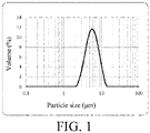
- Fig. 1 shows a volume-basis particle size distribution curve of the anode active material in Example 2. It can be seen from Fig. 1 that the particle size distribution of the anode active material particles of Example 2 is relatively uniform, and narrow. The lithium ion battery prepared with the anode active material of Example 2 shows a satisfactory cycle performance and swelling resistance.
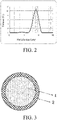
- Fig. 2 shows a volume-basis particle size distribution curve of the anode active material in Comparative Example 2. It can be seen from Fig. 2 that the anode active material of Comparative Example 2 has a certain number of small particles, so the cycle performance is poor. The presence of small fine particles accelerates the etching of the particles by the electrolytic solution and thus accelerates the deterioration of the cycle performance. Moreover, since the small particles are quickly etched by the electrolytic solution, a large amount of by-products are produced on the surface, so the swelling resistance of the lithium ion battery prepared therefrom is worse than the swelling resistance of the lithium ion battery prepared with the anode active material of Comparative Example 2.
- Fig. 3 illustrates a schematic structural diagram of an anode active material in an example of the present application.
- the inner layer 1 is a silicon composite substrate, and the outer layer 2 is an oxide MeO y layer containing the carbon material.
- the oxide MeO y layer coating the silicon composite substrate can act as an HF trapping agent, and the oxide can react with HF in the electrolytic solution to reduce the content of HF in the electrolytic solution during the cycle process, and reduce the etching of HF on the surface of the silicon material, thereby further improving the cycle performance of the material.
- Doping a carbon material in the oxide MeO y layer is beneficial for the formation of the lithium ion conductors after intercalation of the lithium during the first charge and discharge process, and is beneficial for achieving the conduction of ions.
- doping a certain amount of carbon in the oxide MeO y layer can enhance the conductivity of the anode active material.
- Fig. 4 is a schematic structural diagram of an anode active material in another example of the present application.
- the inner layer 1 is a silicon composite substrate
- the middle layer 2 is an oxide MeO y layer containing a carbon material
- the outer layer 3 is a polymer layer containing a carbon material.
- the anode active material of the present application may only have the silicon composite substrate and the polymer layer, but without the MeO y layer. That is, the polymer layer of the present application can be directly coated on the surface of the silicon composite substrate.
- the CNTs can be bound to the surface of the anode active material by the polymer, which is beneficial for the improvement of the interface stability of the CNTs on the surface of the anode active material, thereby improving cycle performance.
- Fig. 5 shows an X-ray diffraction (XRD) pattern of an anode active material in Example 25 of the present application.
- XRD X-ray diffraction
- the I 2 /I 1 value When the I 2 /I 1 value is greater than 1, the stress in a local region of the anode active material will sharply increase during intercalation of the lithium, so that the structure of the anode active material is degraded during the cycle process. In addition, due to the generation of the distribution of nanocrystals, the diffusion capacity of the ions in the grain boundary during diffusion of the ion process will be affected.
- the inventors of the present application finds that when the I 2 /I 1 value meets 0 ⁇ I 2 /I 1 ⁇ 1, the anode active material has good cycle performance, and the lithium ion battery prepared with the same has good swelling resistance.
- Fig. 6 shows an X-ray diffraction (XRD) pattern of an anode active material in Comparative Example 3 of the present application. It can be seen from Fig. 6 that the anode active material of Comparative Example 3 has an I 2 /I 1 value that is significantly greater than 1. Compared with the anode active material of Example 25, the anode active material of Comparative Example 3 has poor cycle performance, and the lithium ion battery prepared with the same has a high swelling rate and poor rate performance.
- XRD X-ray diffraction
- Figs. 7 and 8 show scanning electron microscopy (SEM) images of the anode active materials in Example 25 and Comparative Example 3, respectively. The particle size distribution can be visually observed from Figs. 7 and 8. Fig. 8 shows that a certain number of small particles are present in the anode active material of Comparative Example 3.
- the embodiments of the present application provide an anode.
- the anode includes a current collector and an anode active material layer located on the current collector.
- the anode active material layer includes an anode material according to the embodiments of the present application.
- the anode active material layer comprises a binder.
- the binder includes, but is not limited to, polyvinyl alcohol, carboxymethyl cellulose, hydroxypropyl cellulose, diacetyl cellulose, polyvinyl chloride, carboxylated polyvinyl chloride, polyvinyl fluoride, a polymer containing ethylene oxide, polyvinylpyrrolidone, polyurethane, polytetrafluoroethylene, poly(1,1-vinylidene fluoride), polyethylene, polypropylene, styrene-butadiene rubber, acrylic styrene butadiene rubber, epoxy resin, Nylon and so on.
- the anode active material layer comprises a conductive material.
- the conductive material includes, but is not limited to, natural graphite; artificial graphite; carbon black; acetylene black; Ketjen black; carbon fibers; a metal powder; metal fibers; copper; nickel; aluminum; silver; or polyphenylene derivatives.
- the current collector includes, but is not limited to, a copper foil, a nickel foil, a stainless steel foil, a titanium foil, nickel foam, copper foam, or a polymeric substrate coated with a conductive metal.
- the anode can be obtained by mixing an active material, a conductive material, and a binder in a solvent to prepare an active material composition, and coating the active material composition on a current collector.
- the solvent may include, but is not limited to, N-methylpyrrolidone or the like.
- a material capable of being applied to a cathode in the embodiment of the present application, a composition and a preparation method thereof include any technology disclosed in prior art.
- the cathode is a cathode disclosed in US Patent Application US9812739B , which is incorporated into the present application by full text reference.
- the cathode includes a current collector and a cathode active material layer on the current collector.
- the cathode active material includes, but is not limited to, lithium cobalt oxide (LiCoO2), lithium nickel cobalt manganese (NCM) ternary material, lithium iron phosphate (LiFePO4), or lithium manganese oxide (LiMn204).
- LiCoO2 lithium cobalt oxide
- NCM lithium nickel cobalt manganese
- LiFePO4 lithium iron phosphate
- LiMn204 lithium manganese oxide
- the cathode active material layer further comprises a binder, and optionally a conductive material.
- the binder improves the binding of the cathode active material particles to each other and the binding of the cathode active material to the current collector.
- the binder includes, but is not limited to, polyvinyl alcohol, hydroxypropyl cellulose, diacetyl cellulose, polyvinyl chloride, carboxylated polyvinyl chloride, polyvinyl fluoride, a polymer containing ethylene oxide, polyvinylpyrrolidone, polyurethane, polytetrafluoroethylene, poly(1,1-vinylidene fluoride), polyethylene, polypropylene, styrene-butadiene rubber, acrylated styrene butadiene rubber, epoxy resins, Nylon and so on.
- the conductive material includes, but is not limited to, a carbon based material, a metal based material, a conductive polymer, and a mixture thereof.
- the carbon-based material is selected from natural graphite, artificial graphite, carbon black, acetylene black, Ketjen black, carbon fiber, or any combinations thereof.
- the metal based material is selected from metal powders, metal fibers, copper, nickel, aluminum, and silver.
- the conductive polymer is a polyphenylene derivative.
- the current collector includes, but is not limited to, aluminum.
- the cathode may be prepared by a preparation method well known in the art.
- the cathode can be obtained by the following method: mixing an active material, a conductive material and a binder in a solvent to prepare an active material composition, and coating the active material composition on a current collector.
- the solvent may include, but is not limited to, N-methylpyrrolidone or the like.
- An electrolytic solution that can be used in the embodiments of the present application may be an electrolytic solution known in prior art.
- the electrolytic solution comprises an organic solvent, a lithium salt, and an additive.
- the organic solvent used in the electrolytic solution according to the present application may be any organic solvent known in the art and capable of serving as a solvent of the electrolytic solution.
- the electrolyte used in the electrolytic solution according to the present application is not limited, and may be any electrolyte known in the art.
- the additive used in the electrolytic solution according to the present application may be any additive known in the art and capable of serving as an additive of the electrolytic solution.
- the organic solvent includes, but is not limited to, ethylene carbonate (EC), propylene carbonate (PC), diethyl carbonate (DEC), ethyl methyl carbonate (EMC), dimethyl carbonate (DMC), propylene carbonate or ethyl propionate.
- the lithium salt includes at least one of an organic lithium salt or an inorganic lithium salt.
- the lithium salt includes, but is not limited to, lithium hexafluorophosphate (LiPF 6 ), lithium tetrafluoroborate (LiBF 4 ), lithium difluorophosphate (LiPO 2 F 2 ), lithium bis(trifluoromethanesulfonyl)imide LiN(CF 3 SO 2 ) 2 (LiTFSI), lithium bis(fluorosulfonyl)imide Li(N(SO 2 F) 2 (LiFSI), lithium bis(oxalato)borate LiB(C 2 O 4 ) 2 (LiBOB), or lithium difluoro(oxalato)borate LiBF 2 (C 2 O 4 ) (LiDFOB).
- LiPF 6 lithium hexafluorophosphate
- LiBF 4 lithium tetrafluoroborate
- LiPO 2 F 2 lithium difluorophosphate
- LiN(CF 3 SO 2 ) 2 LiTFSI
- LiFSI lithium bis(fluorosulf
- the concentration of the lithium salt in the electrolytic solution is about 0.5 mol/L to 3 mol/L, about 0.5 mol/L to 2 mol/L, or about 0.8 mol/L to 1.5 mol/L.
- a separator is provided between the cathode and the anode to prevent a short circuit.
- the material and shape of the separator that can be used in the embodiment of the present application are not particularly limited, and may be any of the techniques disclosed in the prior art.
- the separator includes a polymer or an inorganic substance or the like formed by a material which is stable in the electrolytic solution of the present application.
- the separator may include a substrate layer and a surface treatment layer.
- the substrate layer is a non-woven fabric, a film, or a composite film having a porous structure.
- the material of the substrate layer is selected from at least one of polyethylene, polypropylene, polyethylene terephthalate, and polyimide.
- a porous polypropylene film, a porous polyethylene film, a polypropylene nonwoven fabric, a polyethylene non-woven fabric, and a porous polypropylene-polyethylene-polypropylene composite film may be used.
- At least one surface of the substrate layer is provided with a surface treatment layer.
- the surface treatment layer may be a polymer layer or an inorganic layer, or a layer formed by mixing the polymer and the inorganic material.
- the inorganic layer comprises inorganic particles and a binder.
- the inorganic particles are one or a combination of several selected from the group consisting of alumina, silicon dioxide, magnesia, titania, hafnium dioxide, tin oxide, cerium dioxide, nickel oxide, zinc oxide, calcium oxide, zirconia, yttria, silicon carbide, eboehmite, aluminum hydroxide, magnesium hydroxide, calcium hydroxide and barium sulfate, or a combination of more than one thereof.
- the binder is one selected from the group consisting of polyvinylidene fluoride, copolymer of vinylidene fluoride-hexafluoropropylene, polyamide, polyacrylonitrile, polyacrylate ester, polyacrylic acid, polyacrylate salt, polyvinylpyrrolidone, polyvinyl ether, polymethyl methacrylate, polytetrafluoroethylene, and polyhexafluoropropylene.
- the polymer layer contains a polymer, and the material of the polymer is selected from at least one of polyamide, polyacrylonitrile, an acrylate polymer, polyacrylic acid, polyacrylate, polyvinylpyrrolidone, polyvinyl ether, polyvinylidene fluoride or poly(vinylidene fluoride-hexafluoropropylene).
- the embodiments of the present application provide an electrochemical device including any device that undergoes an electrochemical reaction.
- the electrochemical device of the present application includes a cathode having a cathode active material capable of occluding and releasing metal ions; an anode according to an embodiment of the present application; an electrolytic solution; and a separator located between the cathode and the anode.
- the electrochemical device of the present application includes, but is not limited to, all kinds of primary batteries, secondary batteries, fuel cells, solar cells, or capacitors.
- the electrochemical device is a lithium secondary battery.
- the lithium secondary battery includes, but is not limited to, a lithium metal secondary battery, a lithium ion secondary battery, a lithium polymer secondary battery or a lithium ion polymer secondary battery.
- the electronic device of the present application may be any device using the electrochemical device according to an embodiment of the present application.
- the electronic device comprises, but is not limited to, notebook computers, pen-input computers, mobile computers, e-book players, portable phones, portable fax machines, portable copy machine, portable printers, stereo headphones, video recorders, liquid crystal display television, portable cleaners, portable CD players, minidisc players, transceivers, electronic notebooks, calculators, memory cards, portable recorders, radios, backup power supplies, motors, vehicles, motorcycles, power-assisted scooters, bicycles, lighting fixture, toys, game consoles, clocks, electric tools, flash light, cameras, large household batteries, or lithium ion capacitors, and the like.
- the lithium ion battery is taken as an example and the preparation of the lithium-ion battery is described in conjunction with specific embodiments. Those skilled in the art would understand that the preparation method described in the present application is only an example, and any other suitable preparation methods are within the scope of the present application.
- the following describes embodiments of the lithium-ion batteries battery according to the present application and comparative examples for performance evaluation.
- LiPF 6 was added to a mixed solvent of propylene carbonate (PC), ethylene carbonate (EC), and diethyl carbonate (DEC) (at a weight ratio of about 1:1:1), and then uniformly mixed, wherein the concentration of LiPF 6 was about 1.15 mol/L. About 7.5 wt% of fluoroethylene carbonate (FEC) was added, and mixed uniformly to obtain an electrolytice solution.
- PC propylene carbonate
- EC ethylene carbonate
- DEC diethyl carbonate
- FEC fluoroethylene carbonate
- the anode active material obtained in the examples and comparative examples, conductive carbon black and a modified polyacrylic acid (PAA) binder were added to deionized water at a weight ratio of about 80:10:10, and were stirred to form a slurry.
- a scraper was used for coating to form a coating layer with a thickness of 100 ⁇ m.
- the coating layer was dried in a vacuum drying oven at about 85°C for about 12 hr, and then cut into a wafer with a diameter of about 1 cm with a punching machine in a dry environment.
- a lithium metal sheet was used as a counter electrode, and a Ceglard composite membrane was used as a separator, and an electrolytic solution was added to assemble a button battery.
- a LAND series battery test was used to perform charge and discharge tests on the battery to test the charge and discharge capacity of the battery.
- the first Coulombic efficiency was the ratio of the charge capacity to the discharge capacity.
- LiCoO 2 , conductive carbon black and polyvinylidene fluoride (PVDF) were fully stirred and mixed in an N-methylpyrrolidone solvent system at a weight ratio of about 95%:2.5%:2.5%, to prepare a cathode slurry.
- the cathode slurry prepared was coated on an aluminum foil as a cathode current collector, dried, and then cold-pressed to obtain the cathode.
- Graphite, the anode active material prepared according to the examples and comparative examples, a conductive agent (conductive carbon black, Super P ® ), and the PAA binder were mixed at a weight ratio of about 70%:15%:5%:10%, an appropriate amount of water was added, and kneaded at a solid content of about 55 wt% to 70 wt%. An appropriate amount of water was added to adjust the viscosity of the slurry to about 4000 Pa ⁇ s to 6000 Pa ⁇ s to prepare an anode slurry.
- the anode slurry prepared was coated on a copper foil as an anode current collector, dried, and then cold-pressed to obtain the anode.
- LiPF 6 was added to a mixed solvent of propylene carbonate (PC), ethylene carbonate (EC), and diethyl carbonate (DEC) (at a weight ratio of about 1:1:1), and uniformly mixed, wherein the concentration of LiPF 6 was about 1.15 mol/L.
- PC propylene carbonate
- EC ethylene carbonate
- DEC diethyl carbonate
- FEC fluoroethylene carbonate
- a porous PE polymer film was used as a separator.
- the cathode, separator, and anode were stacked in an order such that the separator was located between the cathode and anode to isolate the cathode and anode, and a battery cell was obtained by winding.
- the battery cell was placed in an outer package, and the electrolytic solution was injected, and the outer package was packaged. After formation, degassing, trimming and other processes, the lithium ion battery was obtained.
- the test temperature was 25/45 °C.
- the battery was charged to 4.4 V at a constant current of 0.7 C and then charged to 0.025C at a constant voltage, allowed to stand for 5 min, and discharged to 3.0 V at 0.5 C.
- the capacity obtained in this step was the initial capacity.
- the cycle of charge at 0.7 C/discharge at 0.5 C was repeated, and ratio of the capacity of each step to the initial capacity was obtained, from which a capacity attenuation curve was obtained.
- the cycle number at 25°C to a capacity retention rate of 90% was recorded as the room-temperature cycle performance of the battery, and the cycle number at 45°C to a capacity retention rate of 80% was recorded as the high-temperature cycle performance of the battery.
- the cycle performances of the materials were compared by comparing the cycle number s in the above two conditions.
- the battery was discharged to 3.0V at 0.2 C, allowed to stand for 5 min, charged to 4.45V at 0.5 C, charged to 0.05 C at a constant voltage, and allowed to stand for 5 min.
- the discharge rate was adjusted, and the battery was respectively discharged at 0.2 C, 0.5 C, 1 C, 1.5 C, and 2.0 C, to obtain the discharge capacity.
- the capacity obtained at each rate and the capacity obtained at 0.2 C were compared.
- the rate performance was compared by comparing the ratios at 2 C and 0.2 C.
- the thickness of a fresh battery of half charge (50% state of charge (SOC)) was measured by a screw micrometer. After 400 cycles, the thickness of the battery of full charge (100% SOC) was measured by a screw micrometer, and compared with the thickness of the initial fresh battery of half charge (50% SOC), to obtain the swelling rate of the fully charged (100% SOC) battery at this time.
- SOC state of charge
- a commercially-available silicon oxide SiO x (0.6 ⁇ x ⁇ 1.5, Dv50: about 5 ⁇ m) is graded to prepare the anode active materials of Examples 1-3 and Comparative Examples 1-2.
- Table 1-1 and Table 1-2 show the performance test results of the anode active materials in Examples 1-3 and Comparative Examples 1 and 2.
- Table 1-1 D V 50 ( ⁇ m) Dn10/Dv50 Carbon content (wt%) Specific surface area/ (m 2 .g -1 ) Capacity per gram * (mAh.g _1 ) First efficiency Example 1 5.0 0.3 0.028 1.56 1672 68.8% Example 2 5.0 0.5 0.030 1.42 1683 69.0% Example 3 5.0 0.6 0.029 1.23 1682 69.2% Comparative Example 1 5.0 0.05 0.031 3.78 1681 68.1% Comparative Example 2 5.0 0.7 0.028 1.18 1680 68.2% Table 1-2 No.
- Example 1 375 350 8.0% 84.6%
- Dn10/Dv50 is the ratio of the diameter Dn10 corresponding to a cumulative number percentage being 10% in the number-basis distribution curve to the diameter Dv50 corresponding to a cumulative volume percentage being 50% in the volume basis distribution curve obtained by the laser scattering particle size analyzer. The larger the Dn10/Dv50 value is, the fewer small particles there are in the material.
- the lithium ion battery prepared with an anode active material meeting 0.1 ⁇ Dn10/Dv50 ⁇ 0.6 has a cycle performance, rate performance and swelling resistance that are all better than those of the lithium ion battery prepared with an anode active material meeting Dn10/Dv50 ⁇ 0.1 or 0.6 ⁇ Dn10/Dv50.
- the anode active materials of Examples 4-12 were prepared as follows:
- Table 2-1 shows the process conditions for preparing the anode active materials in Examples 4-12.
- Example 4 100 g Polyvinylpyrrolidone 2.21 g 1 g aluminum isopropoxide N 2 flow rate: 1.5 L/min, heating at 3°C/min to 600°C, holding for 2 hr
- Example 5 100 g Polyvinylpyrrolidone 2.21 g 1 g isopropyl titanate N 2 flow rate: 1.5 L/min, heating at 3°C/min to 600°C, holding for 2 hr
- Example 6 100 g Polyvinylpyrrolidone 2.21 g 0.5 g isopropyl titanate + 0.5 g aluminum isopropoxide N 2 flow rate: 1.5 L/min, heating at 3°C/min to 600°C, holding for 2 hr
- Example 7 100 g Polyvinylpyrrolidone 2.21 g
- Table 2-2 and Table 2-3 show the performance test results of the anode active materials in Example 2 and Examples 4-12.
- Table 2-2 Types of metal element Metal content (wt%) Carbon content (wt%) Dv50 ( ⁇ m) Dn10/Dv50 Specific surface area (m 2 .g -1 ) Capacity per gram ⁇ (mAh.g -1 ) First efficiency
- Example 4 A1 0.125% 0.300 5.1 0.51 1.45 1682 68.4%
- Example 5 Ti 0.125% 0.300 5.2 0.52 1.47 1678 74.0%
- Example 6 Al+Ti 0.125% 0.300 5.1 0.52 1.53 1682 70.3%
- Example 8 A1 0.500% 0.300 5.3 0.52 1.98 1662 68.2%
- Example 9 A1 1.000% 0.300 5.4 0.53 2.40 1640 67.4%
- Example 2 390 375 7.9% 84.8%
- Example 4 500 450 7.5% 88.6%
- Example 5 420 392 8.0% 85.2%
- Example 6 433 398 8.2% 85.4%
- Example 7 402 388 8.1% 85.1%
- Example 8 520 465 7.4% 88.4%
- Example 9 528 468 7.2% 87.6%
- Example 10 490 420 7.8% 85.2%
- Example 11 485 402 7.9% 85.0%
- Example 12 463 387 7.8% 85.7%
- Example 2 From the test results of Example 2 and Examples 4-12, it can be seen that coating the oxide MeO y layer on the anode active material that meets the condition of 0.1 ⁇ Dn10/Dv50 ⁇ 0.6 can further improve the cycle performance and rate performance of the lithium ion battery, while the first efficiency and battery swelling rate do not change significantly.
- the anode active materials of Examples 13-17 and 20-21 were prepared as follows:
- the preparation method of the anode active material in Examples 18 and 19 was similar to the above method, except that the solvent in the first step of Examples 18 and 19 was N-vinylpyrrolidone.
- Table 3-1 shows the compositions of the anode active materials in Examples 13-21.
- Table 3-1 No. Carbon material CNT content Types of polymer Polymer content
- Example 13 SCNT 1.0 wt.% CMC-Na 1.5 wt.%
- Example 14 MCNT 1.0 wt.% CMC-Na 1.5 wt.%
- Example 16 SCNT 0.1 wt.% CMC-Na 1.5 wt.%
- Example 17 SCNT 5 wt.% CMC-Na 1.5 wt.%
- Example 18 SCNT 1 wt.% PVP 1.5 wt.%
- Example 19 SCNT 1 wt.% PVDF 1.5 wt.%
- Example 20 SCNT 1 wt.% PAANa 1.5 wt.%
- Example 21 SCNT 1 wt.% CMC-Na 4 wt.%
- Table 3-2 shows the performance test results of the anode active materials in Examples 4 and 13-21.
- Table 3-2 No. Number of cycles at 25°C to 90% Number of cycles at 45°C to 80% Swelling rate of battery after 400 cycles at 45°C Rate performance
- Example 4 500 450 7.5% 88.6%
- Example 14 516 464 7.7% 88.7%
- Example 15 570 565 8.1% 88.6%
- Example 16 527 478 7.7% 88.2%
- Example 18 605 638 7.4% 87.8%
- Example 19 612 634 7.6% 87.5%
- Example 21 618 651 7.4% 83.2%
- Example 4 It can be seen from the test results of Example 4 and Examples 13-21 that coating a certain amount of CNT-containing polymer layer on the anode active material in Example 4 can significantly improve the cycle performance and rate performance of lithium ion batteries.
- Table 4-1 shows the specific process parameters in Steps (1)-(5), and Table 4-2 shows the specific process parameters in Step (6).
- Table 4-1 No. SiO 2 :Si (molar ratio) Pressure (Pa) Heating temperature (°C) Heating time (h) heat-treatment after grading Example 22 1:1 10 1350 20 / Example 23 1:1 10 1350 20 600°C, 2h Example 24 1:1 10 1350 20 800°C, 2h Comparative Example 3 1:1 10 1350 20 1000°C, 2h Table 4-2 No.
- Table 4-3 shows the compositions of the anode active materials in Examples 22-24 and Comparative Example 3.
- Types of polymer Polymer content (wt%) Example 22 0.41 Al 0.125 0.300 SCNT 1.0 CMC-Na 1.5
- Example 23 0.64 Al 0.125 0.300 SCNT 1.0 CMC-Na 1.5
- Example 24 1 Al 0.125 0.300 SCNT 1.0 CMC-Na 1.5 Comparative Example 3 2.5 Al 0.125 0.300 SCNT 1.0 CMC-Na 1.5
- Table 4-4 shows the performance parameters of the lithium ion batteries prepared with the anode active materials of Examples 22-24 and Comparative Examples 3. Table 4-4 No. Number of cycles at 25°C to 90% Number of cycles at 45°C to 80% Swelling rate of battery after 400 cycles at 45°C Rate performance Example 22 653 678 7.6% 90.2% Example 23 620 650 8.0% 89.4% Example 24 600 623 8.3% 88.2% Comparative Example 3 567 582 9.4% 85.2%
- the anode active materials of Examples 25-27 and Comparative Example 4 were prepared as follows: The preparation methods of the anode active materials of Examples 25-27 and Comparative Example 4 were similar to that of Examples 22-24 and Comparative Example 3, except that the preparation methods of Examples 25-27 and Comparative Example 4 do not include step (7). That is, the anode active materials of Examples 25-27 and Comparative Example 4 only had a metal oxide coating, but without a polymer coating.
- Table 5-1 shows the compositions of the anode active materials in Examples 25-27 and Comparative Example 4.
- Example 25 0.41 Al 0.125 0.300
- Example 26 0.64 Al 0.125 0.300
- Example 27 1 Al 0.125 0.300 Comparative Example 4 2.5 Al 0.125 0.300
- Table 5-2 shows the performance test results of the anode active materials in Examples 25-27 and Comparative Example 4.
- Table 5-2 No. Number of cycles at 25°C to 90% Number of cycles at 45°C to 80% Swelling rate of battery after 400 cycles at 45°C Rate performance
- Example 26 590 650 8.2 88.4%
- Example 27 575 623 8.0 87.5% Comparative Example 4 532 582 9.5 86.9%
Landscapes
- Chemical & Material Sciences (AREA)
- Chemical Kinetics & Catalysis (AREA)
- Electrochemistry (AREA)
- General Chemical & Material Sciences (AREA)
- Composite Materials (AREA)
- Engineering & Computer Science (AREA)
- Materials Engineering (AREA)
- Inorganic Chemistry (AREA)
- Battery Electrode And Active Subsutance (AREA)
- Electric Double-Layer Capacitors Or The Like (AREA)
Applications Claiming Priority (1)
| Application Number | Priority Date | Filing Date | Title |
|---|---|---|---|
| PCT/CN2019/118582 WO2021092867A1 (zh) | 2019-11-14 | 2019-11-14 | 负极材料及包含其的电化学装置和电子装置 |
Publications (3)
| Publication Number | Publication Date |
|---|---|
| EP4012803A1 true EP4012803A1 (de) | 2022-06-15 |
| EP4012803A4 EP4012803A4 (de) | 2022-08-24 |
| EP4012803B1 EP4012803B1 (de) | 2025-10-01 |
Family
ID=75911598
Family Applications (1)
| Application Number | Title | Priority Date | Filing Date |
|---|---|---|---|
| EP19952437.2A Active EP4012803B1 (de) | 2019-11-14 | 2019-11-14 | Negatives elektrodenmaterial, elektrochemische vorrichtung damit und elektronische vorrichtung |
Country Status (5)
| Country | Link |
|---|---|
| US (1) | US12341184B2 (de) |
| EP (1) | EP4012803B1 (de) |
| JP (1) | JP7653356B2 (de) |
| ES (1) | ES3053880T3 (de) |
| WO (1) | WO2021092867A1 (de) |
Family Cites Families (30)
| Publication number | Priority date | Publication date | Assignee | Title |
|---|---|---|---|---|
| JP4081676B2 (ja) | 2003-04-24 | 2008-04-30 | 信越化学工業株式会社 | 非水電解質二次電池用負極材 |
| JP5131429B2 (ja) * | 2006-12-15 | 2013-01-30 | 信越化学工業株式会社 | 非水電解質二次電池用負極及びその製造方法 |
| JP5215978B2 (ja) | 2009-10-28 | 2013-06-19 | 信越化学工業株式会社 | 非水電解質二次電池用負極材及びその製造方法並びにリチウムイオン二次電池 |
| WO2012077268A1 (ja) * | 2010-12-07 | 2012-06-14 | 株式会社大阪チタニウムテクノロジーズ | リチウムイオン二次電池負極材用粉末、これを用いたリチウムイオン二次電池負極およびキャパシタ負極、ならびにリチウムイオン二次電池およびキャパシタ |
| KR101724012B1 (ko) * | 2012-08-23 | 2017-04-07 | 삼성에스디아이 주식회사 | 실리콘계 음극활물질, 그 제조방법 및 이를 포함하는 리튬 이차 전지 |
| US9893353B2 (en) * | 2013-05-23 | 2018-02-13 | Shin-Etsu Chemical Co., Ltd. | Negative electrode material for nonaqueous electrolyte secondary batteries, and secondary battery |
| WO2015015548A1 (ja) * | 2013-07-29 | 2015-02-05 | 株式会社日立製作所 | リチウムイオン二次電池用負極材料、リチウムイオン二次電池用負極、リチウムイオン二次電池、およびリチウムイオン二次電池用負極材料の製造法 |
| CN103682279B (zh) | 2013-12-27 | 2016-01-27 | 浙江大学 | 一种硅基复合锂离子电池负极材料及其制备方法和应用 |
| CN104766995B (zh) | 2015-03-31 | 2017-03-15 | 宁德时代新能源科技股份有限公司 | 一种电解液添加剂及其在锂离子电池中的应用 |
| JP6460400B2 (ja) * | 2015-03-31 | 2019-01-30 | Tdk株式会社 | 安定化リチウム粉、及びそれを用いたリチウムイオン二次電池 |
| CN107925074B (zh) | 2015-07-31 | 2022-03-01 | 信越化学工业株式会社 | 锂离子二次电池用负极材料、其制造方法和锂离子二次电池 |
| KR20170048184A (ko) * | 2015-10-23 | 2017-05-08 | 주식회사 엘지화학 | 이차전지용 음극활물질, 이의 제조 방법 및 이를 포함하는 이차전지 |
| JP6981203B2 (ja) * | 2016-11-22 | 2021-12-15 | 三菱ケミカル株式会社 | 非水系二次電池用負極材、非水系二次電池用負極及び非水系二次電池 |
| US10971722B2 (en) * | 2018-03-02 | 2021-04-06 | Global Graphene Group, Inc. | Method of manufacturing conducting elastomer composite-encapsulated particles of anode active materials for lithium batteries |
| CN108807849B (zh) * | 2018-05-16 | 2019-11-15 | 宁德时代新能源科技股份有限公司 | 负极极片及含有它的二次电池 |
| CN109461880B (zh) * | 2018-10-17 | 2020-08-28 | 宁德时代新能源科技股份有限公司 | 负极极片及电池 |
| CN109449446B (zh) | 2018-10-17 | 2020-09-11 | 宁德时代新能源科技股份有限公司 | 二次电池 |
| CN111146410B (zh) * | 2018-11-05 | 2021-03-02 | 宁德时代新能源科技股份有限公司 | 负极活性材料及电池 |
| CN109616614B (zh) | 2018-12-14 | 2020-12-11 | 宁德新能源科技有限公司 | 负极极片和使用其的电化学装置和电子装置 |
| CN109638254B (zh) * | 2018-12-17 | 2020-09-25 | 宁德新能源科技有限公司 | 负极材料及使用其的电化学装置和电子装置 |
| CN112436115B (zh) * | 2018-12-29 | 2021-12-28 | 宁德时代新能源科技股份有限公司 | 正极活性材料、正极极片及电化学储能装置 |
| CN109920987A (zh) | 2019-02-20 | 2019-06-21 | 宁德新能源科技有限公司 | 负极材料及包含所述负极材料的电化学装置及电子装置 |
| CN109888217B (zh) | 2019-02-20 | 2021-08-03 | 宁德新能源科技有限公司 | 负极活性材料和使用其的负极极片以及电化学和电子装置 |
| CN114975980A (zh) * | 2019-03-19 | 2022-08-30 | 宁德新能源科技有限公司 | 负极材料及使用其的电化学装置和电子装置 |
| CN109980199B (zh) | 2019-03-20 | 2020-09-29 | 宁德新能源科技有限公司 | 负极活性材料及其制备方法及使用该负极活性材料的装置 |
| CN110071280B (zh) | 2019-05-14 | 2021-02-26 | 山东泰纳新材料科技有限公司 | 一种铝酸锂固态电解质包覆硅基负极材料及其制备方法 |
| CN112018334A (zh) * | 2019-05-28 | 2020-12-01 | 贝特瑞新材料集团股份有限公司 | 一种硅氧化物/碳复合负极材料及其制备方法和锂离子电池 |
| CN110391406A (zh) | 2019-07-01 | 2019-10-29 | 深圳市比克动力电池有限公司 | 一种锂离子电池硅氧负极材料及其制备方法、锂离子电池 |
| CN110444750B (zh) | 2019-08-07 | 2021-08-13 | 宁德新能源科技有限公司 | 负极材料及包含其的电化学装置和电子装置 |
| CN110416543A (zh) | 2019-08-07 | 2019-11-05 | 宁德新能源科技有限公司 | 负极材料及包含其的电化学装置和电子装置 |
-
2019
- 2019-11-14 JP JP2021536168A patent/JP7653356B2/ja active Active
- 2019-11-14 ES ES19952437T patent/ES3053880T3/es active Active
- 2019-11-14 WO PCT/CN2019/118582 patent/WO2021092867A1/zh not_active Ceased
- 2019-11-14 EP EP19952437.2A patent/EP4012803B1/de active Active
-
2022
- 2022-03-09 US US17/690,257 patent/US12341184B2/en active Active
Also Published As
| Publication number | Publication date |
|---|---|
| US20220199969A1 (en) | 2022-06-23 |
| US12341184B2 (en) | 2025-06-24 |
| EP4012803B1 (de) | 2025-10-01 |
| EP4012803A4 (de) | 2022-08-24 |
| WO2021092867A1 (zh) | 2021-05-20 |
| JP7653356B2 (ja) | 2025-03-28 |
| JP2022515216A (ja) | 2022-02-17 |
| ES3053880T3 (en) | 2026-01-27 |
Similar Documents
| Publication | Publication Date | Title |
|---|---|---|
| US12183915B2 (en) | Anode material, and electrochemical device and electronic device using the same | |
| CN110911636B (zh) | 负极材料及包含其的电化学装置和电子装置 | |
| US12266786B2 (en) | Negative electrode, and electrochemical apparatus and electronic apparatus including same | |
| CN110797520B (zh) | 负极材料及包含其的电化学装置和电子装置 | |
| CN111029543A (zh) | 负极材料及包含其的电化学装置和电子装置 | |
| US20220199988A1 (en) | Anode material, electrochemical device and electronic device comprising the same | |
| CN110911635B (zh) | 负极材料及包含其的电化学装置和电子装置 | |
| US12614718B2 (en) | Anode material, electrochemical device and electronic device including the same | |
| CN110890531B (zh) | 负极材料及包含其的电化学装置和电子装置 | |
| CN111146414A (zh) | 负极材料及包含其的电化学装置和电子装置 | |
| CN111146421B (zh) | 负极材料及包含其的电化学装置和电子装置 | |
| CN111146420A (zh) | 负极材料及包含其的电化学装置和电子装置 | |
| CN110931742A (zh) | 负极及包含其的电化学装置和电子装置 | |
| US20220271281A1 (en) | Anode material, electrochemical device and electronic device comprising the same | |
| US12482812B2 (en) | Anode material, electrochemical device and electronic device including the same | |
| JP7203990B2 (ja) | 負極材料、並びに、それを含む電気化学装置及び電子装置 | |
| US12444737B2 (en) | Anode material, electrochemical device and electronic device comprising the same | |
| US12341184B2 (en) | Anode material, electrochemical device and electronic device comprising the same |
Legal Events
| Date | Code | Title | Description |
|---|---|---|---|
| STAA | Information on the status of an ep patent application or granted ep patent |
Free format text: STATUS: THE INTERNATIONAL PUBLICATION HAS BEEN MADE |
|
| PUAI | Public reference made under article 153(3) epc to a published international application that has entered the european phase |
Free format text: ORIGINAL CODE: 0009012 |
|
| STAA | Information on the status of an ep patent application or granted ep patent |
Free format text: STATUS: REQUEST FOR EXAMINATION WAS MADE |
|
| 17P | Request for examination filed |
Effective date: 20220309 |
|
| AK | Designated contracting states |
Kind code of ref document: A1 Designated state(s): AL AT BE BG CH CY CZ DE DK EE ES FI FR GB GR HR HU IE IS IT LI LT LU LV MC MK MT NL NO PL PT RO RS SE SI SK SM TR |
|
| A4 | Supplementary search report drawn up and despatched |
Effective date: 20220722 |
|
| RIC1 | Information provided on ipc code assigned before grant |
Ipc: H01M 10/0525 20100101ALI20220715BHEP Ipc: H01M 4/62 20060101ALI20220715BHEP Ipc: H01M 4/48 20100101ALI20220715BHEP Ipc: H01M 4/38 20060101ALI20220715BHEP Ipc: H01M 4/36 20060101AFI20220715BHEP |
|
| STAA | Information on the status of an ep patent application or granted ep patent |
Free format text: STATUS: EXAMINATION IS IN PROGRESS |
|
| DAV | Request for validation of the european patent (deleted) | ||
| DAX | Request for extension of the european patent (deleted) | ||
| 17Q | First examination report despatched |
Effective date: 20230127 |
|
| GRAP | Despatch of communication of intention to grant a patent |
Free format text: ORIGINAL CODE: EPIDOSNIGR1 |
|
| STAA | Information on the status of an ep patent application or granted ep patent |
Free format text: STATUS: GRANT OF PATENT IS INTENDED |
|
| INTG | Intention to grant announced |
Effective date: 20250429 |
|
| GRAS | Grant fee paid |
Free format text: ORIGINAL CODE: EPIDOSNIGR3 |
|
| GRAA | (expected) grant |
Free format text: ORIGINAL CODE: 0009210 |
|
| STAA | Information on the status of an ep patent application or granted ep patent |
Free format text: STATUS: THE PATENT HAS BEEN GRANTED |
|
| AK | Designated contracting states |
Kind code of ref document: B1 Designated state(s): AL AT BE BG CH CY CZ DE DK EE ES FI FR GB GR HR HU IE IS IT LI LT LU LV MC MK MT NL NO PL PT RO RS SE SI SK SM TR |
|
| REG | Reference to a national code |
Ref country code: GB Ref legal event code: FG4D Ref country code: CH Ref legal event code: F10 Free format text: ST27 STATUS EVENT CODE: U-0-0-F10-F00 (AS PROVIDED BY THE NATIONAL OFFICE) Effective date: 20251001 |
|
| REG | Reference to a national code |
Ref country code: DE Ref legal event code: R096 Ref document number: 602019076545 Country of ref document: DE |
|
| REG | Reference to a national code |
Ref country code: IE Ref legal event code: FG4D |
|
| PGFP | Annual fee paid to national office [announced via postgrant information from national office to epo] |
Ref country code: NL Payment date: 20251015 Year of fee payment: 7 |
|
| REG | Reference to a national code |
Ref country code: NL Ref legal event code: FP |
|
| PGFP | Annual fee paid to national office [announced via postgrant information from national office to epo] |
Ref country code: DE Payment date: 20251007 Year of fee payment: 7 |
|
| PGFP | Annual fee paid to national office [announced via postgrant information from national office to epo] |
Ref country code: GB Payment date: 20251016 Year of fee payment: 7 |
|
| PGFP | Annual fee paid to national office [announced via postgrant information from national office to epo] |
Ref country code: IT Payment date: 20251126 Year of fee payment: 7 |
|
| PGFP | Annual fee paid to national office [announced via postgrant information from national office to epo] |
Ref country code: FR Payment date: 20251008 Year of fee payment: 7 |
|
| REG | Reference to a national code |
Ref country code: ES Ref legal event code: FG2A Ref document number: 3053880 Country of ref document: ES Kind code of ref document: T3 Effective date: 20260127 |
|
| PGFP | Annual fee paid to national office [announced via postgrant information from national office to epo] |
Ref country code: ES Payment date: 20251212 Year of fee payment: 7 |
|
| REG | Reference to a national code |
Ref country code: AT Ref legal event code: MK05 Ref document number: 1843484 Country of ref document: AT Kind code of ref document: T Effective date: 20251001 |
|
| REG | Reference to a national code |
Ref country code: LT Ref legal event code: MG9D |
|
| PG25 | Lapsed in a contracting state [announced via postgrant information from national office to epo] |
Ref country code: NO Free format text: LAPSE BECAUSE OF FAILURE TO SUBMIT A TRANSLATION OF THE DESCRIPTION OR TO PAY THE FEE WITHIN THE PRESCRIBED TIME-LIMIT Effective date: 20260101 |
|
| PG25 | Lapsed in a contracting state [announced via postgrant information from national office to epo] |
Ref country code: AT Free format text: LAPSE BECAUSE OF FAILURE TO SUBMIT A TRANSLATION OF THE DESCRIPTION OR TO PAY THE FEE WITHIN THE PRESCRIBED TIME-LIMIT Effective date: 20251001 Ref country code: HR Free format text: LAPSE BECAUSE OF FAILURE TO SUBMIT A TRANSLATION OF THE DESCRIPTION OR TO PAY THE FEE WITHIN THE PRESCRIBED TIME-LIMIT Effective date: 20251001 Ref country code: FI Free format text: LAPSE BECAUSE OF FAILURE TO SUBMIT A TRANSLATION OF THE DESCRIPTION OR TO PAY THE FEE WITHIN THE PRESCRIBED TIME-LIMIT Effective date: 20251001 |
|
| PG25 | Lapsed in a contracting state [announced via postgrant information from national office to epo] |
Ref country code: RS Free format text: LAPSE BECAUSE OF FAILURE TO SUBMIT A TRANSLATION OF THE DESCRIPTION OR TO PAY THE FEE WITHIN THE PRESCRIBED TIME-LIMIT Effective date: 20260101 |
|
| PG25 | Lapsed in a contracting state [announced via postgrant information from national office to epo] |
Ref country code: IS Free format text: LAPSE BECAUSE OF FAILURE TO SUBMIT A TRANSLATION OF THE DESCRIPTION OR TO PAY THE FEE WITHIN THE PRESCRIBED TIME-LIMIT Effective date: 20260201 |
|
| PG25 | Lapsed in a contracting state [announced via postgrant information from national office to epo] |
Ref country code: PT Free format text: LAPSE BECAUSE OF FAILURE TO SUBMIT A TRANSLATION OF THE DESCRIPTION OR TO PAY THE FEE WITHIN THE PRESCRIBED TIME-LIMIT Effective date: 20260202 Ref country code: CZ Free format text: LAPSE BECAUSE OF FAILURE TO SUBMIT A TRANSLATION OF THE DESCRIPTION OR TO PAY THE FEE WITHIN THE PRESCRIBED TIME-LIMIT Effective date: 20251001 |
|
| PG25 | Lapsed in a contracting state [announced via postgrant information from national office to epo] |
Ref country code: PL Free format text: LAPSE BECAUSE OF FAILURE TO SUBMIT A TRANSLATION OF THE DESCRIPTION OR TO PAY THE FEE WITHIN THE PRESCRIBED TIME-LIMIT Effective date: 20251001 |
|
| PG25 | Lapsed in a contracting state [announced via postgrant information from national office to epo] |
Ref country code: LV Free format text: LAPSE BECAUSE OF FAILURE TO SUBMIT A TRANSLATION OF THE DESCRIPTION OR TO PAY THE FEE WITHIN THE PRESCRIBED TIME-LIMIT Effective date: 20251001 |