EP4012206B1 - Leaning vehicle - Google Patents
Leaning vehicle Download PDFInfo
- Publication number
- EP4012206B1 EP4012206B1 EP20861584.9A EP20861584A EP4012206B1 EP 4012206 B1 EP4012206 B1 EP 4012206B1 EP 20861584 A EP20861584 A EP 20861584A EP 4012206 B1 EP4012206 B1 EP 4012206B1
- Authority
- EP
- European Patent Office
- Prior art keywords
- ball
- inner edge
- leaning
- ball stud
- front wheels
- Prior art date
- Legal status (The legal status is an assumption and is not a legal conclusion. Google has not performed a legal analysis and makes no representation as to the accuracy of the status listed.)
- Active
Links
Images


Classifications
-
- B—PERFORMING OPERATIONS; TRANSPORTING
- B62—LAND VEHICLES FOR TRAVELLING OTHERWISE THAN ON RAILS
- B62D—MOTOR VEHICLES; TRAILERS
- B62D7/00—Steering linkage; Stub axles or their mountings
- B62D7/16—Arrangement of linkage connections
-
- F—MECHANICAL ENGINEERING; LIGHTING; HEATING; WEAPONS; BLASTING
- F16—ENGINEERING ELEMENTS AND UNITS; GENERAL MEASURES FOR PRODUCING AND MAINTAINING EFFECTIVE FUNCTIONING OF MACHINES OR INSTALLATIONS; THERMAL INSULATION IN GENERAL
- F16C—SHAFTS; FLEXIBLE SHAFTS; ELEMENTS OR CRANKSHAFT MECHANISMS; ROTARY BODIES OTHER THAN GEARING ELEMENTS; BEARINGS
- F16C11/00—Pivots; Pivotal connections
- F16C11/04—Pivotal connections
- F16C11/06—Ball-joints; Other joints having more than one degree of angular freedom, i.e. universal joints
- F16C11/0619—Ball-joints; Other joints having more than one degree of angular freedom, i.e. universal joints the female part comprising a blind socket receiving the male part
- F16C11/0623—Construction or details of the socket member
- F16C11/0628—Construction or details of the socket member with linings
- F16C11/0633—Construction or details of the socket member with linings the linings being made of plastics
-
- B—PERFORMING OPERATIONS; TRANSPORTING
- B60—VEHICLES IN GENERAL
- B60G—VEHICLE SUSPENSION ARRANGEMENTS
- B60G3/00—Resilient suspensions for a single wheel
- B60G3/18—Resilient suspensions for a single wheel with two or more pivoted arms, e.g. parallelogram
- B60G3/20—Resilient suspensions for a single wheel with two or more pivoted arms, e.g. parallelogram all arms being rigid
-
- B—PERFORMING OPERATIONS; TRANSPORTING
- B60—VEHICLES IN GENERAL
- B60G—VEHICLE SUSPENSION ARRANGEMENTS
- B60G7/00—Pivoted suspension arms; Accessories thereof
- B60G7/005—Ball joints
-
- F—MECHANICAL ENGINEERING; LIGHTING; HEATING; WEAPONS; BLASTING
- F16—ENGINEERING ELEMENTS AND UNITS; GENERAL MEASURES FOR PRODUCING AND MAINTAINING EFFECTIVE FUNCTIONING OF MACHINES OR INSTALLATIONS; THERMAL INSULATION IN GENERAL
- F16C—SHAFTS; FLEXIBLE SHAFTS; ELEMENTS OR CRANKSHAFT MECHANISMS; ROTARY BODIES OTHER THAN GEARING ELEMENTS; BEARINGS
- F16C11/00—Pivots; Pivotal connections
- F16C11/04—Pivotal connections
- F16C11/06—Ball-joints; Other joints having more than one degree of angular freedom, i.e. universal joints
- F16C11/0619—Ball-joints; Other joints having more than one degree of angular freedom, i.e. universal joints the female part comprising a blind socket receiving the male part
- F16C11/0623—Construction or details of the socket member
- F16C11/0628—Construction or details of the socket member with linings
- F16C11/0633—Construction or details of the socket member with linings the linings being made of plastics
- F16C11/0638—Construction or details of the socket member with linings the linings being made of plastics characterised by geometrical details
-
- B—PERFORMING OPERATIONS; TRANSPORTING
- B60—VEHICLES IN GENERAL
- B60G—VEHICLE SUSPENSION ARRANGEMENTS
- B60G2200/00—Indexing codes relating to suspension types
- B60G2200/10—Independent suspensions
- B60G2200/14—Independent suspensions with lateral arms
- B60G2200/144—Independent suspensions with lateral arms with two lateral arms forming a parallelogram
-
- B—PERFORMING OPERATIONS; TRANSPORTING
- B60—VEHICLES IN GENERAL
- B60G—VEHICLE SUSPENSION ARRANGEMENTS
- B60G2204/00—Indexing codes related to suspensions per se or to auxiliary parts
- B60G2204/40—Auxiliary suspension parts; Adjustment of suspensions
- B60G2204/416—Ball or spherical joints
-
- B—PERFORMING OPERATIONS; TRANSPORTING
- B60—VEHICLES IN GENERAL
- B60G—VEHICLE SUSPENSION ARRANGEMENTS
- B60G2300/00—Indexing codes relating to the type of vehicle
- B60G2300/12—Cycles; Motorcycles
- B60G2300/122—Trikes
-
- B—PERFORMING OPERATIONS; TRANSPORTING
- B60—VEHICLES IN GENERAL
- B60G—VEHICLE SUSPENSION ARRANGEMENTS
- B60G2300/00—Indexing codes relating to the type of vehicle
- B60G2300/45—Rolling frame vehicles
-
- B—PERFORMING OPERATIONS; TRANSPORTING
- B62—LAND VEHICLES FOR TRAVELLING OTHERWISE THAN ON RAILS
- B62D—MOTOR VEHICLES; TRAILERS
- B62D9/00—Steering deflectable wheels not otherwise provided for
- B62D9/02—Steering deflectable wheels not otherwise provided for combined with means for inwardly inclining vehicle body on bends
-
- B—PERFORMING OPERATIONS; TRANSPORTING
- B62—LAND VEHICLES FOR TRAVELLING OTHERWISE THAN ON RAILS
- B62K—CYCLES; CYCLE FRAMES; CYCLE STEERING DEVICES; RIDER-OPERATED TERMINAL CONTROLS SPECIALLY ADAPTED FOR CYCLES; CYCLE AXLE SUSPENSIONS; CYCLE SIDECARS, FORECARS, OR THE LIKE
- B62K5/00—Cycles with handlebars, equipped with three or more main road wheels
- B62K5/02—Tricycles
- B62K5/05—Tricycles characterised by a single rear wheel
-
- B—PERFORMING OPERATIONS; TRANSPORTING
- B62—LAND VEHICLES FOR TRAVELLING OTHERWISE THAN ON RAILS
- B62K—CYCLES; CYCLE FRAMES; CYCLE STEERING DEVICES; RIDER-OPERATED TERMINAL CONTROLS SPECIALLY ADAPTED FOR CYCLES; CYCLE AXLE SUSPENSIONS; CYCLE SIDECARS, FORECARS, OR THE LIKE
- B62K5/00—Cycles with handlebars, equipped with three or more main road wheels
- B62K5/08—Cycles with handlebars, equipped with three or more main road wheels with steering devices acting on two or more wheels
-
- B—PERFORMING OPERATIONS; TRANSPORTING
- B62—LAND VEHICLES FOR TRAVELLING OTHERWISE THAN ON RAILS
- B62K—CYCLES; CYCLE FRAMES; CYCLE STEERING DEVICES; RIDER-OPERATED TERMINAL CONTROLS SPECIALLY ADAPTED FOR CYCLES; CYCLE AXLE SUSPENSIONS; CYCLE SIDECARS, FORECARS, OR THE LIKE
- B62K5/00—Cycles with handlebars, equipped with three or more main road wheels
- B62K5/10—Cycles with handlebars, equipped with three or more main road wheels with means for inwardly inclining the vehicle body on bends
-
- F—MECHANICAL ENGINEERING; LIGHTING; HEATING; WEAPONS; BLASTING
- F16—ENGINEERING ELEMENTS AND UNITS; GENERAL MEASURES FOR PRODUCING AND MAINTAINING EFFECTIVE FUNCTIONING OF MACHINES OR INSTALLATIONS; THERMAL INSULATION IN GENERAL
- F16C—SHAFTS; FLEXIBLE SHAFTS; ELEMENTS OR CRANKSHAFT MECHANISMS; ROTARY BODIES OTHER THAN GEARING ELEMENTS; BEARINGS
- F16C2326/00—Articles relating to transporting
- F16C2326/20—Land vehicles
- F16C2326/26—Bicycle steering or suspension
Definitions
- the present teaching relates to a leaning vehicle, and more particularly to a leaning vehicle with two steerable front wheels.
- Leaning vehicles are known.
- a leaning vehicle has a vehicle body that leans leftward when the vehicle turns left and leans rightward when the vehicle turns right.
- Some of such leaning vehicles have two steerable front wheels, for example, as disclosed in International Patent Application Publication No. WO 2019/044471 (Patent Literature 1).
- Patent Literature 1 discloses a leaning vehicle with two leaning and steerable front wheels.
- Patent Literature 2 For leaning vehicles with two leaning and steerable front wheels, for example, International Patent Application Publication No. 2014/046285 (Patent Literature 2) has suggested a joint mechanism that allows the two front wheels to be steered within a large angle range.
- Patent Literature 3 Japanese Patent Application Publication No. 2016-211671
- Patent Literature 4 Japanese Utility Model Application Publication No. H5-12738
- Patent Literature 5 Japanese Patent Application Publication No. H01-229787
- a rotation shaft having a rotation axis extending in a forward- and-backward direction and a rotation shaft having a rotation axis extending in an upward-and-downward direction are positioned separately, and in order to prevent these rotation shafts from being in contact with each other, the joint mechanism as a whole must be made large. Consequently, the part around the two leaning and steerable front wheels increases in size.
- the joint mechanisms disclosed in Patent Literatures 3 and 4 are for cars, it is difficult to use these joint mechanisms in leaning vehicles.
- the joint mechanism of Patent Literature 3 specifically, the tilt angle range and the rotation angle range of the ball stud are large, which allows the two front wheels to be steered within a sufficiently large steering angle range during leaning of the two front wheels.
- the joint mechanism has insufficient strength against a force of pulling out the ball stud, and therefore, it is difficult to use the joint mechanism in a leaning vehicle.
- the joint mechanism of Patent Literature 4 has a structure that provides sufficient strength against a force of pulling out the ball stud and against a force of pushing in the ball stud.
- the tilt angle range of the ball stud is small, and therefore, it is difficult to use the joint mechanism in a leaning vehicle.
- An object of the present teaching is to provide a leaning vehicle with two leaning and steerable front wheels that is expanded in the steering angle range of the two front wheels during leaning of the two front wheels without causing an increase in the size of the part around the two front wheels.
- a leaning vehicle includes: a vehicle body that is capable of leaning leftward and rightward of the leaning vehicle; two front wheels that lean leftward and rightward together with the vehicle body and are steerable leftward and rightward; and a support mechanism that allows the two front wheels to be supported by the vehicle body and includes: a first member; a second member connected to the first member; and a joint mechanism that connects the first member and the second member in such a manner so as to allow the first member and the second member to be displaced relative to each other along with leaning of the two front wheels and to allow the first member and the second member to be displaced relative to each other along with steering of the two front wheels.
- the joint mechanism is a ball joint that connects the first member and the second member and includes: a ball stud including a spherical ball part and a bar-like first shaft; and a metal holder that holds the ball part in such a manner that the ball part is freely rotatable, the metal holder having an open end part pierced by the ball stud.
- the open end part is formed in such a manner that: the open end part has an inner edge including the open end part including a first inner edge part, a second inner edge part, a third inner edge part, and a fourth inner edge part; when the two front wheels are steered or leaned from their respective steering neutral and leaning neutral positions, the tilt angle of the ball stud varies between the first and second inner edge parts, which are each formed at positions outward from the circumference of a maximum width part of the ball part with respect to a direction perpendicular to a central axis of the ball stud that is in its steering neutral and leaning neutral position; and the third and fourth inner edge parts, which are each formed at positions inward from the circumference of the maximum width part of the ball part, are positioned separately between the first and second inner edge parts.
- the joint mechanism By positioning the joint mechanism in the above-defined leaning vehicle in such a manner that the tilt angle of the ball stud, which is variable between the first and second inner edge parts, or the rotation angle of the ball stud corresponds to the steering angle of the two front wheels, it is possible to expand the steering angle range of the two front wheels during leaning of the two front wheels. This will be described below.
- the tilt angle of the ball stud which is variable between the first and second inner edge parts, corresponds to the steering angle of the two front wheels.
- the tilt angle of the ball stud varies within the range between the first and second inner edge parts. Since the first and second inner edge part are formed at positions outward from the circumference of a maximum width part of the ball part, the first and second inner edge part do not impose such a strict restriction to the tilt angle of the ball stud. Accordingly, the tilt angle range of the ball stud becomes large. Even during leaning of the two front wheels, the ball stud can tilt at a large tilt angle within the range between the first and second inner edge parts. Thus, the steering angle range during leaning of the two front wheels can be expanded.
- the rotation angle of the ball stud is an angle by which the ball stud rotates around its central axis from a view looking in the extending direction of the central axis of the ball stud.
- the rotation angle of the ball stud is the rotation angle of the ball stud around its central axis. Since the ball part of the ball stud is held by the holder in such a manner as to be freely rotatable, the rotation angle range of the ball stud is large. Therefore, even while the two front wheels are leaning, the ball stud can tilt at a large angle. Accordingly, the steering angle range during leaning of the two front wheels can be expanded.
- the joint mechanism is a ball joint, and the ball part of the ball stud is held by the holder in such a manner as to be freely rotatable. Therefore, the first member and the second member are allowed to be displaced relative to each other when the two front wheels are leaned and/or steered, and there is no need to increase the size of the part around the two front wheels.
- the third and fourth inner edge parts are separately formed between the first and second inner edge parts, at positions inward from the circumference of the maximum width part of the ball part, and accordingly, the third and fourth inner edge parts function as a stopper that stops the ball stud from being pulled out of the holder. This eliminates the need to increase the size of the ball part. As a result, the part around the two front wheels is prevented from increasing in size.
- the leaning vehicle may be a three-wheeled vehicle with one rear wheel as well or may be a four-wheeled vehicle with two rear wheels as well.
- the leaning vehicle may be a straddled vehicle.
- a straddled vehicle is a vehicle to be straddled by a rider.
- the leaning vehicle may be a vehicle with a sit-in type seat.
- the leaning vehicle may include a drive source that moves the vehicle body.
- the drive source may be of any type that provides a driving force to the leaning vehicle.
- the drive source may be an engine, an electric motor, or a combination of an engine and an electric motor.
- the leaning vehicle may include a shock absorber that absorbs load applied to the two front wheels.
- the leaning vehicle may include a steering mechanism that provides a mechanical connection between the steering handlebar and the two front wheels, or a steering mechanism that does not provide a mechanical connection between the steering handlebar and the two front wheels.
- the steering mechanism that does not provide a mechanical connection between the steering handlebar and the two front wheels for example, includes a steering actuator that steers the two front wheels in accordance with the rider's manipulation of the steering handlebar.
- the vehicle body includes a vehicle body frame.
- the vehicle body frame may be a frame assembled from a plurality of components, or a frame formed as a one-piece body of a plurality of components.
- the material of the vehicle body frame may be metal such as aluminum, iron, or the like, synthetic resin such as CFRP or the like, or a combination of metal and synthetic resin.
- the vehicle body frame may be a monocoque type that is formed of exterior parts of the leaning vehicle or may be a semi-monocoque type, part of which also functions as the exterior of the leaning vehicle.
- the vehicle body for example, is capable of leaning to the left and right of the leaning vehicle. For example, the vehicle body leans leftward when the leaning vehicle turns left and leans rightward when the leaning vehicle turns right.
- each of the two front wheels is supported by the vehicle body, for example, in such a manner as to be rotatable around an axis extending in the upward-and-downward direction of the vehicle body.
- the axis extending in the upward-and-downward direction of the vehicle body does not necessarily extend in the vertical direction when the vehicle body is in an upright position.
- the axis extending in the upward-and-downward direction of the vehicle body may tilt backward, with respect to the vehicle body, from the vertical direction when the vehicle body is in the upright position.
- the upper end of the axis extending in the upward-and-downward direction of the vehicle body may be positioned more backward than the lower end of the axis extending in the upward-and-downward direction of the vehicle body.
- the two front wheels are arranged, for example, side by side in the leftward-and-rightward direction of the leaning vehicle.
- the support mechanism that allows the two front wheels to be supported by the vehicle body includes a mechanism that leans the two front wheels to the left or right of the leaning vehicle together with the vehicle body.
- the support mechanism for example, includes a mechanism that steers the two front wheels to the left or right of the leaning vehicle.
- the support mechanism for example, includes a suspension.
- the suspension is, for example, an independent suspension.
- the first member and the second member are only required to have a mutual relationship that allows the first member and the second member to be displaced relative to each other along with leaning of the two front wheels and to be displaced relative to each other along with steering of the two front wheels. Either of the first member or the second member is, for example, a tie rod.
- the other of the first member or the second member is, for example, a knuckle that swings around a steering axis of each of the two front wheels, or a pitman arm that swings around a swing axis extending in the upward-and-downward direction.
- the first member and the second member are not limited to a tie rod, a knuckle, or a pitman arm.
- the support mechanism may include a plurality of first members and/or a plurality of second members.
- the leaning vehicle includes a plurality of joint mechanisms.
- the ball stud is, for example, made of metal.
- the ball part and the first shaft are made of metal. It is only necessary that the surface of the ball part is partly spherical.
- the ball part is, for example, connected to the first shaft.
- the means of connecting the ball part and the first shaft includes forming the ball part and the first shaft as a one-piece body.
- the first shaft functions to connect the first member or the second member to the ball stud.
- the first shaft for example, may include a bolt part with an external male thread.
- the first shaft for example, may have a hole on the outer surface.
- the first shaft for example, may include a nut with an interior female thread.
- the cross-section of the first shaft in a place perpendicular to the central axis of the first shaft may be, for example, circular or polygonal.
- the central axis of the first shaft for example, passes through the center of the ball part.
- the center of the ball part is the center of a circle that indicates the outer edge of the ball part when the ball part is cut in a plane perpendicular to the central axis of the first shaft. More specifically, the center of the ball part is the center of the circular cross section with a maximum diameter which is obtained when the ball part is cut at the maximum width part.
- the center of the ball part means the center of the circle that indicates the circumference of the maximum width part of the ball part from a view looking in the extending direction of the central axis of the ball stud.
- the central axis of the first shaft does not necessarily pass through the center of the ball part.
- the center of the ball part may be off the central axis of the first shaft.
- the central axis of the ball stud for example, may be the same as the central axis of the first shaft or may be parallel to the central axis of the first shaft.
- a member that is made of a softer material than both the ball part and the holder is positioned between the ball part and the holder.
- a resin member can be used as the member. This member reduces the friction between the ball part and the holder.
- the open end part is formed to surround the central axis of the ball stud from a view looking in the extending direction of the ball stud in its steering neutral and leaning neutral position.
- the inner edge of the open end part includes a first inner edge part, a second inner edge part, a third inner edge part, and a fourth inner edge part.
- the first inner edge part, the second inner edge part, the third and fourth inner edge parts may form only part of the inner edge.
- Each of the first inner edge part, the second inner edge part, the third and fourth inner edge parts may be a straight line, a curved line, or a combination of a curved line and a straight line.
- the first and second inner edge parts of the inner edge are at positions outward from the circumference of the maximum width part of the ball part with respect to a direction perpendicular to the central axis of the ball stud in its steering neutral and leaning neutral position.
- the first and second edge parts are the parts of the inner edge that are positioned at longer distances, with respect to a direction perpendicular to the central axis of the ball stud in its steering neutral and leaning neutral position, from the central axis of the ball stud than the distance between the central axis of the ball stud and the circumference of the maximum width part of the ball part.
- the first and second inner edge parts may be at the same position or at different positions with respect to the direction parallel to the central axis of the ball stud in its steering neutral and leaning neutral position.
- the third and fourth inner edge parts are the parts of the inner edge that are positioned inward from the circumference of the maximum width part of the ball part with respect to the direction perpendicular to the central axis of the ball stud in its steering neutral and leaning neutral position.
- the third and fourth inner edge parts are the parts of the inner edge that are positioned at shorter distances, with respect to the direction perpendicular to the central axis of the ball stud in its steering neutral and leaning neutral position, from the central axis of the ball stud than the distance between the central axis of the ball stud and the circumference of the maximum width part of the ball part.
- the third and fourth inner edge parts may be at the same position or at different positions with respect to the direction parallel to the central axis of the ball stud in its steering neutral and leaning neutral position. From a view looking in the extending direction of the central axis of the ball stud in its steering neutral and leaning neutral position, the first and second inner edge parts are formed, for example, in such a manner as to be line symmetry with respect to a line perpendicular to the central axis of the ball stud.
- the first and second inner edge parts are formed, for example, in such a manner as to be point symmetry with respect to the central axis of the ball stud.
- the third and fourth inner edge parts are formed, for example, in such a manner as to be line symmetry with respect to a line perpendicular to the central axis of the ball stud.
- the third and fourth inner edge parts are formed, for example, in such a manner as to be point symmetry with respect to the central axis of the ball stud.
- the first and second inner edge parts are longer than the third and fourth inner edge parts.
- the distance between the first and second inner edge parts is longer than the diameter of the ball part, and the distance between the third and fourth inner edge parts is shorter than the diameter of the ball part.
- the tilt angle of the ball stud is the tilt angle of the ball stud relative to the holder.
- the variable range of the tilt angle of the ball stud is determined by the shape of the ball stud and the shape of the open end part of the holder.
- the ball stud is kept from being pulled out of the holder by the third and fourth inner edge parts of the open end part of the holder.
- the third and fourth inner edge parts permit the ball joint to have sufficient strength in the pull-out direction.
- the strength of the ball joint in the pull-out direction is how hard it is for the ball stud to come off the holder.
- a ball joint has a trade-off problem between an expansion in the variable range of the tilt angle of the ball stud and the maintenance of the durability of the ball joint.
- the variable range of the tilt angle of the ball stud is designed, for example, depending on the required performance of the leaning vehicle.
- the rotation angle of the ball stud of a ball joint is the rotation angle of the ball stud relative to the holder.
- the variable range of the rotation angle of the ball stud of a ball joint is not necessarily determined by the shape of the ball stud and the shape of the open end part of the holder.
- the variable range of the rotation angle of the ball stud of the ball joint is designed, for example, depending on the required performance of the leaning vehicle.
- variable range of the tilt angle of the ball stud and the rotation angle of the ball stud for example, have a mutual relation such that the tilt angle of the ball stud becomes smaller as the ball stud rotates clockwise or counterclockwise from the position where the ball stud is tilted at the maximum tilt angle.
- the relation between the tilt angle and the rotation angle of the ball stud is, for example, such that the tilt angle of the ball stud becomes smaller continuously during the rotation of the ball stud.
- the relation between the tilt angle and the rotation angle of the ball stud is, for example, such that the tilt angle of the ball stud becomes smaller intermittently during the rotation of the ball stud.
- the open end part is preferably formed in such a manner that the first and second inner edge parts are positioned between the center of the ball part and the ball-side end (the end near the ball part) of the first shaft with respect to the direction parallel to the central axis of the ball stud in its steering neutral and leaning neutral position and that the ball-side end of the first shaft is positioned between either of the first or second inner edge part and either of the third or fourth inner edge part with respect to the direction parallel to the central axis of the ball stud that is in its steering neutral and leaning neutral position.
- the third and fourth inner edge parts function as a stopper that stops the ball stud from being pulled out of the holder. This eliminates the need to increase the size of the ball part. As a result, the part around the two front wheels is prevented from increasing in size.
- the ball-side end of the first shaft for example, includes an end to be connected to the ball part.
- the end of the first shaft to be connected to the ball part for example, is connected to an end of the ball part to be connected to the first shaft.
- the end of the ball part to be connected to the first shaft for example, includes a first-shaft-side end of the spherical surface of the ball part.
- the open end part is formed in such a manner that the first and second inner edge parts allow the tilt angle of the ball stud to be variable within the range of ⁇ 25 degrees from the steering neutral and leaning neutral position.
- the variable range of the tilt angle of the ball stud is large. Accordingly, when the tilt angle of the ball stud corresponds to the steering angle of the two front wheels, the steering angle range during leaning of the two front wheels can be expanded.
- the mark " ⁇ " the positive mark (+) shows the direction of the tilt angle toward either one of the first or second inner edge part, and the negative mark (-) shows the direction of the tilt angle toward the other of the first or second inner edge part.
- the tilt angle of the ball stud may be limited by contact of the ball stud with a part other than the inner edge of the open end part.
- the contact of the ball stud with a part other than the inner edge of the open end part includes contact of the ball stud with a stopper.
- the stopper for example, is attached to the leaning vehicle.
- the tilt angle of the ball stud may be limited by contact of the ball stud with a part other than the inner edge of the open end part.
- a contact edge may be formed at a different position from the position of the inner edge of the open end part with respect to the direction parallel to the central axis of the ball stud in its steering neutral and leaning neutral position, or alternatively, may be formed at a different position from the position of the inner edge of the open end part with respect to a direction perpendicular to the central axis of the ball stud in its steering neutral and leaning neutral position.
- the holder In addition to the open end part pierced by the ball stud (which will hereinafter be referred to as a first open end part), the holder has another open end part (which will hereinafter be referred to as a second open end part), which is to be covered by a cap.
- the first open end part includes the first inner edge part, the second inner edge part, the third inner edge part, and the fourth inner edge part.
- the second open end part is covered by a cap in such a manner that the ball part of the ball stud is kept in the holder with the ball stud piercing through the first open end part.
- Keeping the ball part of the ball stud in the holder includes keeping the ball part of the ball stud in the holder in such a manner as to prevent the ball part from coming off from the holder.
- the cap is made of, for example, metal.
- the second open end part has a diameter larger than the diameter of the ball part so that the ball part can pass through the second open end part at the time of assembly of the ball joint.
- the cap covers at least part of the second open end part so as to prevent the ball part from passing through the second open end part.
- the cap is fixed to the holder.
- the holder is structured in such a manner that: the distance between the first and second inner edge parts of the first open end part is greater than the diameter of the ball part, while the distance between the third and fourth inner edge parts of the first open end part of the holder is smaller than the diameter of the ball part; and additionally, a cap is attached to the second open end part to prevent the ball part from coming off from the holder through the second open end part.
- the present teaching provides a leaning vehicle with two leaning and steerable front wheels that is expanded in the steering angle range during leaning of the two front wheels without causing an increase in the size of the part around the two front wheels.
- a leaning vehicle according to an embodiment of the present teaching will hereinafter be described in detail with reference to the drawings.
- the embodiment described below is merely an example.
- the present teaching shall not be understood to be limited to the embodiment below.
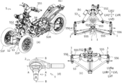
- FIG. 1 includes: (a) a perspective view of the leaning vehicle 5; (b) a back view of a leaning linkage mechanism 53 contained in the leaning vehicle 5; (c) a plan view of the leaning linkage mechanism 53; and (d) a perspective view of a ball joint 1 that serves as a joint mechanism in the leaning vehicle 5.
- the leaning vehicle 5 includes a vehicle body 54, two front wheels 51F, one single rear wheel 51R, and a support mechanism 52. Various directions relative to the leaning vehicle 5 are directions from the perspective of a rider riding the leaning vehicle 5.
- the vehicle body 54 is capable of leaning to the left and right of the leaning vehicle 5.
- the two front wheels 51F lean to the left and right of the leaning vehicle 5 together with the vehicle body 54, and are steerable to the left and right of the leaning vehicle 5.
- the single rear wheel 51R is supported by the vehicle body 54. The single rear wheel 51R leans to the left and right of the leaning vehicle 5 together with the vehicle body 54.
- the support mechanism 52 includes a leaning linkage mechanism 53.
- the leaning linkage mechanism 53 allows the vehicle body 54 and the two front wheels 51F to lean to the left or right of the leaning vehicle 5 when the leaning vehicle 5 turns left or right. Thus, when the leaning vehicle 5 is turning left or right, the vehicle body 54 and the two steerable wheels 51F lean to the left or right of the leaning vehicle 5.
- the support mechanism 52 includes a steering handlebar 551 to be manipulated by a rider, a steering linkage 552, a swing shaft 553, pitman arms 554, tie rods 555, and knuckles 556.
- the steering handlebar 551 is swingably supported by the vehicle body.
- the steering handlebar 551 is connected to the swing shaft 553 via the steering linkage 552.
- the swing shaft 553 swings around a swing axis extending in the upward-and-downward direction.
- the pitman arms 554 are supported by the swing shaft 553 in such a manner as to swing together with the swing shaft 553.
- Each of the tie rods 555 has an end (which will hereinafter be referred to as a first end) that is connected to the corresponding one of the pitman arms 554, and another end (which will hereinafter be referred to as a second end) that is connected to the corresponding one of the knuckles 556.
- a swing of the steering handlebar 551 caused by the rider's manipulation is transmitted to the steering linkage 552, the swing shaft 553, the pitman arms 554, the tie rods 555 and then to the knuckles 556.
- the knuckles 556 swing around a steering axis. Accordingly, the two front wheels 51F swing around the steering axis. Thereby, the two front wheels 51F are steered.
- the tie rods 555 (which are examples of first members) and the pitman arms 554 (which are examples of second members) are connected by ball joints 1 (which are examples of joint mechanisms). In other words, each of the tie rods 555 is connected to the corresponding one of the pitman arms 554 via a ball joint 1.
- the tie rods 555 (which are examples of first members) and the knuckles 556 (which are examples of second members) are connected by ball joints 1. In other words, each of the tie rods 555 is connected to the corresponding one of the knuckles 556 via a ball joint 1.
- the ball joint 1 between each of the tie rods 555 and the corresponding one of the pitman arms 554 connects the tie rod 555 and the pitman arm 554 in such a manner as to allow the tie rod 555 and the pitman arm 554 to be displaced relative to each other along with leaning of the two front wheels 51F and to allow the tie rod 555 and the pitman arm 554 to be displaced relative to each other along with steering of the two front wheels 51F.
- the ball joint 1 between each of the tie rod 555 and the corresponding one of the knuckles 556 connects the tie rod 555 and the knuckle 556 in such a manner as to allow the tie rod 555 and the knuckle 556 to be displaced relative to each other along with leaning of the two front wheels 51F and to allow the tie rod 555 and the knuckle 556 to be displaced relative to each other along with steering of the two front wheels 51F.
- the ball joint 1 includes a ball stud 3, a holder 2, and a cover 4.
- FIG. 1 shows the ball joint 1 with the cover 4 removed.
- FIG. 2 includes: (a) a sectional view of the ball joint 1 along line A-A; (b) a sectional view of the ball joint 1 along line B-B; and (c) a partial plan view of the ball joint 1.
- FIG. 2(c) omits a slide member 25 for a clear illustration of the relationship between each of a first inner edge part 211, a second inner edge part 212, a third inner edge part 213 and a fourth inner edge part 214 at an open end part 21 and a ball part 31 of the ball stud 3.
- the ball joint 1 is illustrated in a coordinate system in which the leftward-and-rightward direction and the upward-and-downward direction are defined when the open end part of the holder 2 is viewed from a point in the extending direction of the central axis CL of the ball stud 3 in the steering neutral and leaning neutral position.
- the direction in which the second shaft 22 of the holder 2 extends is defined as the right.
- the direction from the open end part into the holder 2 is defined as the front.
- Directions in the coordinate system in which the ball joint 1 is illustrated may be same or may be different with directions in the coordinate system in which the leaning vehicle 5 is illustrated. These two coordinate systems are independent of each other.
- FIGS. 1 and 2 show the position of the ball stud 3 when the two front wheels 51F are in their respective steering neutral and leaning neutral positions.
- the ball stud 3 includes a spherical ball part 31 and a bar-like first shaft 32.
- the ball stud 3 is made of metal.
- the holder 2 holds the ball part 31 in such a manner that the ball part 31 is freely rotatable.
- the holder 2 is made of metal.
- the holder 2 includes: a body 21 having an open end part 210 pierced by the ball stud 3; a bar-like second shaft 22 having an axis extending rightward; a connection part 23 connecting the body 21 and the second shaft 22; and a cap 24 that defines a space for the ball part 31 in the body 21.
- the cap 24 is attached to the body 21 in such a manner as to cover another open end of the body 21.
- the cap 24 functions as a stopper that stops the ball stud 3 from being pushed into the holder 2 any further.
- the third inner edge part 213 and the fourth inner edge part 214 function as a stopper that stops the ball stud 3 from being pulled out of the holder 2.
- a resin slide member 25 is positioned between the body 21 and the ball part 31, a resin slide member 25 is positioned.
- the resin slide member 25 is formed into a shape that fits in between the body 21 and the ball part 31.
- the cover 4 is elastically deformable.
- the cover 4 includes a cover body 41, a metal core 42, and a clip 43.
- the cover body 41 is formed from an elastically deformable material.
- the metal core 42 is formed integrally with the cover body 41.
- the first shaft 32 of the ball stud 3 pierces through the metal core 42.
- the cover 4 elastically deforms when the ball joint 1 tilts.
- the open end part 210 includes at least a first inner edge part 211, a second inner edge part 212, a third inner edge part 213, and a fourth inner edge part 214.
- the first inner edge part 211 and the second inner edge part 212 are formed at positions outward from the circumference of the maximum width part of the ball part 31 with respect to a direction perpendicular to the central axis CL of the ball stud 3 in its steering neutral and leaning neutral position.
- the third inner edge part 213 and the fourth inner edge part 214 are formed at positions inward from the circumference of the maximum width part of the ball part 31 with respect to a direction perpendicular to the central axis CL of the ball stud 3 in its steering neutral and leaning neutral position.
- the third inner edge part 211 and the fourth inner edge part 214 are formed at separate positions between the first inner edge part 211 and the second inner edge part 212.
- the open end part 210 is formed in such a manner that the tilt angle ⁇ w of the ball stud 3 varies between the first inner edge part 211 and the second inner edge part 212 when the two front wheels 51F are steered from their respective steering neutral and leaning neutral positions.
- the ball joint 1 is arranged in such a manner that the tilt angle ⁇ w of the ball stud 3, which is variable between the first inner edge part 211 and the second inner edge part 212, corresponds to the steering angle of the two front wheels 51F.
- the open end part 210 is formed in such a manner that the first inner edge part 211 and the second inner edge part 212 are positioned between the center 31C of the ball part 31 and the ball-side end 321 of the first shaft 32 with respect to the direction parallel to the central axis CL of the ball stud 3 in the steering neutral and leaning neutral position. Further, the open end part 210 is formed in such a manner that the ball-side end 321 of the first shaft 32 is positioned between either of the first inner edge part 211 or the second inner edge part 212 and either of the third inner edge part 213 or the fourth inner edge part 214 with respect to the direction parallel to the central axis CL of the ball stud 3 in the steering neutral and leaning neutral position.
- the open end part 210 is formed in such a manner that the first inner edge part 211 and the second inner edge part 212 allow the tilt angle ⁇ w of the ball stud 3 to be variable within the range of ⁇ 25 degrees from the position in the steering neutral and leaning neutral position.
- the ball joint 1 is arranged in such a manner that the tilt angle ⁇ w of the ball stud 3, which is variable between the first inner edge part 211 and the second inner edge part 212, corresponds to the steering angle of the two front wheels 51F. Thereby, the steering angle range during leaning of the two front wheels 51F can be expanded.
- the tilt angle ⁇ w of the ball stud 3 varies between the first inner edge part 211 and the second inner edge part 212.
- the first inner edge part 211 and the second inner edge part 212 are formed at positions outward from the circumference of the maximum width part of the ball part 31, and accordingly, the variable range of the tilt angle ⁇ w of the ball stud 3, which is limited by the first inner edge part 211 and the second inner edge part 212, is not restricted so strictly. As a result, a large tilt angle ⁇ w of the ball stud 3 can be obtained.
- the tilt angle ⁇ w of the ball stud 3 is variable between the first inner edge part 211 and the second inner edge part 212, the tilt angle range of the ball stud 3 becomes large.
- the steering angle range during leaning of the two front wheels 51F can be expanded.
- the ball joint 1 is used as the joint mechanism. Therefore, the ball part 31 of the ball stud 3 can be supported by the holder 2 in such a manner to be freely rotatable, and the tie rod 555 is allowed to be displaced relative to the pitman arm 554 or the knuckle 556 when the two front wheels 51F are leaned and/or steered. This does not cause an increase in the size of the part around the two front wheels 51F.
- the third inner edge part 213 and the fourth inner edge part 214 which are formed at positions inward from the circumference of the maximum width part of the ball part 31, are positioned between the first inner edge part 211 and the second edge part 212 separately, and the third inner edge part 213 and the fourth inner edge part 214 function as a stopper that stops the ball stud 3 from being pulled out of the holder 2. This eliminates the need to increase the size of the ball part 31. Therefore, the part around the two front wheels 51F is not increased in size.
- the reason why the ball stud 3 is required to be hard to come off from the holder 2 is as follows: in a case in which the ball joint 1 is used as a joint mechanism that connects a tie rod 555 with a pitman arm 554 or a knuckle 556, when a disturbance is applied to the front wheels 51F or the steering handlebar 551 during steering of the two front wheels 51F, the connection part between the tie rod 555 and the pitman arm 553 or between the tie rod 555 and the knuckle 556 needs a certain level of strength against a force of pulling out the ball stud 3.
- the leaning vehicle 5 includes a steering mechanism that does not provide a mechanical connection between the steering handlebar 551 and the two front wheels 51F, that is, even when a steering actuator operates to steer the two front wheels 51F in accordance with manipulation applied to the steering handlebar 551, the ball joint 1 is required to have a specific level of strength against a force of pulling out the ball stud 3 so that the steering actuator can continuously control the steering angle against the disturbance inputted to the two front wheels 51F.
- FIG. 3(a) shows the ball joint 1.
- FIGS. 3(b) and 3(c) show ball joints 100 and 101, respectively, which have structures of comparative examples.
- the left half and the right half of the drawing show different sections of the ball joint 100 or 101.
- the left half of the drawing shows a sectional view of the ball joint 100 or 101 on a plane rotated by 90 degrees around the central axis of the ball stud 300 or 301 from the plane of the sectional view shown in the right half of the drawing.
- 3(b) and 3(c) are about hypothetical cases in which these ball joints 100 and 101 are used in a leaning vehicle. However, the descriptions do not show that the ball joints 100 and 101 shown in FIGS. 3(b) and 3(c) are usable in a leaning vehicle.
- the body of the holder 200 has an open end part 210A, and the open end part 210Aincludes two inner edge parts 21A and two inner edge parts 21B.
- the two inner edge parts 21B are separately positioned between the two inner edge parts 21A.
- the two inner edge parts 21A and the two inner edge parts 21B are arranged alternately along the circumference of the open end part 210A.
- the body of the holder 201 has an open end part 210B, and the open end part 210B has an inner edge 21C on the entire circumference.
- the inner edge parts 21A and the inner edge parts 12B are formed at positions inward from the circumference of the maximum width part of the ball part 310, with respect to directions perpendicular to the central axis CL1 of the ball stud 300 in the steering neutral and leaning neutral position. As compared with the inner edge parts 21A, the inner edge parts 21B are positioned more inward from the circumference of the maximum width part of the ball part 310, with respect to the directions perpendicular to the central axis CL1 of the ball stud 300 in the steering neutral and leaning neutral position. Thus, all the inner edge parts 21A and the inner edge parts 21B function as a stopper that stops the ball stud 300 from being pulled out of the holder 200.
- the ball stud 300 is inserted upward in FIG. 3(a) into the body of the holder 200 through another open end part (a second open end part).
- a cap 240 is attached to the body of the holder 200 in such a manner as to cover the second open end part of the body of the holder 200.
- the cap 240 functions as a stopper that stops the ball stud 300 from being pushed into the holder 200 any further.
- the inner edge parts 21A which are positioned outward from the inner edge parts 21B with respect to the directions perpendicular to the central axis CL of the ball stud 300 in the steering neutral and leaning neutral position, are positioned inward from the circumference of the maximum width part of the ball part 310 with respect to the direction perpendicular to the central axis CL1 of the ball stud 300 in the steering neutral and leaning neutral position. Accordingly, as compared with the ball joint 1, the tilt angle range of the ball stud 300 is smaller. Therefore, when the ball joint 100 is used in a leaning vehicle, it is difficult to expand the steering angle range during leaning of two front wheels.
- FIG. 3 the positions of the ball studs 3 and 300 tilted at their respective maximum tilt angles are shown by phantom lines.
- stoppers are attached so as to limit the tilt angles of the ball studs 3 and 300 to smaller angles than their respective maximum tilt angles. Even if such stoppers are attached, it makes no difference as to the fact that the tilt angle range of the ball stud 3 of the ball joint 1 is greater than the tilt angle range of the ball stud 300 of the ball joint 100.
- a cap 242 functions as a stopper that stops the ball stud 301 from being pushed into the holder 201 any further.
- the ball stud 301 is inserted downward in FIG. 3(c) into the holder 201 at the time of assembly of the ball joint 101, and the ball joint 101 lacks in the strength against a force of pulling the ball stud 301 out of the holder 201.
- the ball stud 301 is inserted in the holder 201 through the open end part 210B of the holder 201, which means that the ball stud 301 passes through the open end part 210B, and accordingly, the ball joint 101 lacks in the strength against a force of pulling the ball stud 301 out of the holder 201. Therefore, it is difficult to use the ball joint 100 in a leaning vehicle.
- a modification of the support mechanism 52 will be described.
- the ball joint 1 is positioned in such a manner that the rotation angle ⁇ r of the ball stud 3 corresponds to the steering angle of the two front wheels 51F (not shown in FIG. 4 ) compared to the support mechanism 52.
- the rotation angle ⁇ r of the ball stud 3 means the rotation angle of the ball stud 3 around the central axis CL.
- the steering angle range during leaning of the two front wheels 51F can be expanded.
- the ball part 31 of the ball stud 3 is supported by the holder 2 to be freely rotatable, and therefore, when the two front wheels 51F are steered from their respective steering neutral and leaning neutral positions, the ball stud 3 rotates around the central axis CL.
- the variable range of the rotation angle ⁇ r of the ball stud 3 is large.
- the variable range of the rotation angle ⁇ r of the ball stud 3 is large. Accordingly, the steering angle range during leaning of the two front wheels 51F can be expanded.
Landscapes
- Engineering & Computer Science (AREA)
- Mechanical Engineering (AREA)
- General Engineering & Computer Science (AREA)
- Chemical & Material Sciences (AREA)
- Combustion & Propulsion (AREA)
- Transportation (AREA)
- Physics & Mathematics (AREA)
- Geometry (AREA)
- Pivots And Pivotal Connections (AREA)
- Automatic Cycles, And Cycles In General (AREA)
- Vehicle Body Suspensions (AREA)
- Steering-Linkage Mechanisms And Four-Wheel Steering (AREA)
Applications Claiming Priority (3)
| Application Number | Priority Date | Filing Date | Title |
|---|---|---|---|
| JP2019159312 | 2019-09-02 | ||
| PCT/JP2020/003985 WO2021044646A1 (ja) | 2019-09-02 | 2020-02-03 | ボールジョイント及びリーン車両 |
| PCT/JP2020/033276 WO2021045111A1 (ja) | 2019-09-02 | 2020-09-02 | 傾斜車両 |
Publications (3)
| Publication Number | Publication Date |
|---|---|
| EP4012206A1 EP4012206A1 (en) | 2022-06-15 |
| EP4012206A4 EP4012206A4 (en) | 2022-10-05 |
| EP4012206B1 true EP4012206B1 (en) | 2024-11-06 |
Family
ID=74852416
Family Applications (1)
| Application Number | Title | Priority Date | Filing Date |
|---|---|---|---|
| EP20861584.9A Active EP4012206B1 (en) | 2019-09-02 | 2020-09-02 | Leaning vehicle |
Country Status (4)
| Country | Link |
|---|---|
| US (1) | US20220204079A1 (https=) |
| EP (1) | EP4012206B1 (https=) |
| JP (2) | JPWO2021045111A1 (https=) |
| WO (1) | WO2021045111A1 (https=) |
Families Citing this family (2)
| Publication number | Priority date | Publication date | Assignee | Title |
|---|---|---|---|---|
| US11912098B2 (en) * | 2021-11-16 | 2024-02-27 | Segway Technology Co., Ltd. | Rear suspension system of an all-terrain vehicle and all-terrain vehicle |
| CN114834579A (zh) * | 2022-06-22 | 2022-08-02 | 浙江欧凯车业有限公司 | 一种转向拉杆组件、悬架及车辆 |
Family Cites Families (19)
| Publication number | Priority date | Publication date | Assignee | Title |
|---|---|---|---|---|
| GB737811A (en) * | 1953-02-24 | 1955-10-05 | Wright Howard Clayton | Improvements in or relating to universal joints |
| US4712940A (en) * | 1985-04-23 | 1987-12-15 | Trw Inc. | Joint assembly |
| JPH01229787A (ja) * | 1988-03-11 | 1989-09-13 | Kenichi Masuhara | 車両の懸架装置 |
| JPH03178710A (ja) * | 1989-12-05 | 1991-08-02 | Musashi Seimitsu Ind Co Ltd | ボールジョイントハウジングの製造方法 |
| JPH0726576Y2 (ja) * | 1991-07-31 | 1995-06-14 | 武蔵精密工業株式会社 | ボールジョイントのハウジング |
| JP2002337779A (ja) * | 2001-05-21 | 2002-11-27 | Abanteku:Kk | 三輪車 |
| DE10347814B4 (de) * | 2003-10-10 | 2005-10-20 | Zahnradfabrik Friedrichshafen | Kugelgelenk für ein Kraftfahrzeug |
| US7648148B1 (en) * | 2005-07-06 | 2010-01-19 | Bombardier Recreational Products Inc. | Leaning vehicle with tilting front wheels and suspension therefor |
| JP2009079652A (ja) * | 2007-09-26 | 2009-04-16 | Minebea Co Ltd | 樹脂ライナ付き球面すべり軸受およびロッドエンド軸受 |
| US8851785B1 (en) * | 2009-11-17 | 2014-10-07 | Trw Automotive U.S. Llc | Ball joint |
| US8616773B2 (en) * | 2010-10-21 | 2013-12-31 | The Pullman Company | Hybrid cross axis ball joint bushing |
| CN104487328B (zh) | 2012-09-24 | 2019-08-13 | 雅马哈发动机株式会社 | 车辆 |
| JP6016979B1 (ja) | 2015-05-11 | 2016-10-26 | Thk株式会社 | ボールジョイントおよびボールジョイントの製造方法 |
| WO2016190385A1 (ja) * | 2015-05-28 | 2016-12-01 | Nok株式会社 | ボールジョイント |
| DE102015211005A1 (de) * | 2015-06-16 | 2016-12-22 | Zf Friedrichshafen Ag | Kugelgelenk |
| JP2017170931A (ja) * | 2016-03-18 | 2017-09-28 | ヤマハ発動機株式会社 | 車両 |
| DE102017203711B4 (de) * | 2017-03-07 | 2025-10-09 | Zf Friedrichshafen Ag | Kugelgelenk |
| ES3038714T3 (en) | 2017-09-04 | 2025-10-14 | Yamaha Motor Co Ltd | Leaning vehicle |
| US12434531B2 (en) * | 2023-05-18 | 2025-10-07 | Hyundai Mobis Co., Ltd. | Stabilizer bar link |
-
2020
- 2020-09-02 JP JP2021544004A patent/JPWO2021045111A1/ja not_active Ceased
- 2020-09-02 EP EP20861584.9A patent/EP4012206B1/en active Active
- 2020-09-02 WO PCT/JP2020/033276 patent/WO2021045111A1/ja not_active Ceased
-
2022
- 2022-03-02 US US17/684,756 patent/US20220204079A1/en not_active Abandoned
-
2023
- 2023-12-04 JP JP2023204926A patent/JP2024009383A/ja not_active Withdrawn
Also Published As
| Publication number | Publication date |
|---|---|
| EP4012206A1 (en) | 2022-06-15 |
| US20220204079A1 (en) | 2022-06-30 |
| WO2021045111A1 (ja) | 2021-03-11 |
| JP2024009383A (ja) | 2024-01-19 |
| JPWO2021045111A1 (https=) | 2021-03-11 |
| EP4012206A4 (en) | 2022-10-05 |
Similar Documents
| Publication | Publication Date | Title |
|---|---|---|
| US11827305B2 (en) | Cable routing system of bicycle and stem thereof | |
| US20220204079A1 (en) | Leaning vehicle | |
| US10077090B2 (en) | Inverted tricycle | |
| US8870202B2 (en) | Stabilizer for vehicle suspension | |
| EP3202650B1 (en) | Vehicle | |
| EP3372480A1 (en) | Vehicle | |
| US20190367122A1 (en) | Cable routing system of bicycle | |
| US8353227B2 (en) | Fastening device | |
| EP3372479B1 (en) | Leaning vehicle | |
| US10967930B2 (en) | Multi-link suspension system | |
| EP2530006B1 (en) | Straddle-ridden vehicle | |
| EP4397582A1 (en) | Tilting control device and vehicle comprising the same | |
| EP2477880A1 (en) | Bicycle handlebar grip | |
| KR102103462B1 (ko) | 사출성형용 자전거 프레임 | |
| US20220055711A1 (en) | Tilt-Decoupled Steering Device of a Motorbike | |
| JP2006312449A (ja) | 自動二輪車用調節可能ライザー | |
| US12291302B2 (en) | Internal device having an excentric bearing for a steering column | |
| EP3509934B1 (en) | Steering group of a motor vehicle and motor vehicle thereof | |
| CN206243362U (zh) | 一种多自由度电动平衡车车把 | |
| CN209290080U (zh) | 一种经济型前桥总成 | |
| JP6021546B2 (ja) | ステアリング装置 | |
| JP5223636B2 (ja) | 操舵輪用サスペンション装置 | |
| CN113734336A (zh) | 一种倒三轮转向机构及倒三轮电动车 | |
| CN106627941A (zh) | 一种多自由度电动平衡车车把 | |
| GB2413538A (en) | Motorcycle front fork assembly |
Legal Events
| Date | Code | Title | Description |
|---|---|---|---|
| STAA | Information on the status of an ep patent application or granted ep patent |
Free format text: STATUS: THE INTERNATIONAL PUBLICATION HAS BEEN MADE |
|
| PUAI | Public reference made under article 153(3) epc to a published international application that has entered the european phase |
Free format text: ORIGINAL CODE: 0009012 |
|
| STAA | Information on the status of an ep patent application or granted ep patent |
Free format text: STATUS: REQUEST FOR EXAMINATION WAS MADE |
|
| 17P | Request for examination filed |
Effective date: 20220309 |
|
| AK | Designated contracting states |
Kind code of ref document: A1 Designated state(s): AL AT BE BG CH CY CZ DE DK EE ES FI FR GB GR HR HU IE IS IT LI LT LU LV MC MK MT NL NO PL PT RO RS SE SI SK SM TR |
|
| A4 | Supplementary search report drawn up and despatched |
Effective date: 20220901 |
|
| RIC1 | Information provided on ipc code assigned before grant |
Ipc: B60G 7/00 20060101ALI20220826BHEP Ipc: B62K 5/05 20130101ALI20220826BHEP Ipc: B62K 5/027 20130101ALI20220826BHEP Ipc: B62K 5/10 20130101ALI20220826BHEP Ipc: B62D 9/02 20060101ALI20220826BHEP Ipc: F16C 11/06 20060101AFI20220826BHEP |
|
| DAV | Request for validation of the european patent (deleted) | ||
| DAX | Request for extension of the european patent (deleted) | ||
| P01 | Opt-out of the competence of the unified patent court (upc) registered |
Effective date: 20230527 |
|
| STAA | Information on the status of an ep patent application or granted ep patent |
Free format text: STATUS: EXAMINATION IS IN PROGRESS |
|
| 17Q | First examination report despatched |
Effective date: 20231109 |
|
| GRAP | Despatch of communication of intention to grant a patent |
Free format text: ORIGINAL CODE: EPIDOSNIGR1 |
|
| STAA | Information on the status of an ep patent application or granted ep patent |
Free format text: STATUS: GRANT OF PATENT IS INTENDED |
|
| INTG | Intention to grant announced |
Effective date: 20240513 |
|
| GRAS | Grant fee paid |
Free format text: ORIGINAL CODE: EPIDOSNIGR3 |
|
| GRAA | (expected) grant |
Free format text: ORIGINAL CODE: 0009210 |
|
| STAA | Information on the status of an ep patent application or granted ep patent |
Free format text: STATUS: THE PATENT HAS BEEN GRANTED |
|
| AK | Designated contracting states |
Kind code of ref document: B1 Designated state(s): AL AT BE BG CH CY CZ DE DK EE ES FI FR GB GR HR HU IE IS IT LI LT LU LV MC MK MT NL NO PL PT RO RS SE SI SK SM TR |
|
| REG | Reference to a national code |
Ref country code: GB Ref legal event code: FG4D |
|
| REG | Reference to a national code |
Ref country code: CH Ref legal event code: EP |
|
| REG | Reference to a national code |
Ref country code: DE Ref legal event code: R096 Ref document number: 602020041019 Country of ref document: DE |
|
| REG | Reference to a national code |
Ref country code: IE Ref legal event code: FG4D |
|
| REG | Reference to a national code |
Ref country code: LT Ref legal event code: MG9D |
|
| REG | Reference to a national code |
Ref country code: NL Ref legal event code: MP Effective date: 20241106 |
|
| PG25 | Lapsed in a contracting state [announced via postgrant information from national office to epo] |
Ref country code: PT Free format text: LAPSE BECAUSE OF FAILURE TO SUBMIT A TRANSLATION OF THE DESCRIPTION OR TO PAY THE FEE WITHIN THE PRESCRIBED TIME-LIMIT Effective date: 20250306 Ref country code: IS Free format text: LAPSE BECAUSE OF FAILURE TO SUBMIT A TRANSLATION OF THE DESCRIPTION OR TO PAY THE FEE WITHIN THE PRESCRIBED TIME-LIMIT Effective date: 20250306 Ref country code: HR Free format text: LAPSE BECAUSE OF FAILURE TO SUBMIT A TRANSLATION OF THE DESCRIPTION OR TO PAY THE FEE WITHIN THE PRESCRIBED TIME-LIMIT Effective date: 20241106 |
|
| PG25 | Lapsed in a contracting state [announced via postgrant information from national office to epo] |
Ref country code: FI Free format text: LAPSE BECAUSE OF FAILURE TO SUBMIT A TRANSLATION OF THE DESCRIPTION OR TO PAY THE FEE WITHIN THE PRESCRIBED TIME-LIMIT Effective date: 20241106 Ref country code: NL Free format text: LAPSE BECAUSE OF FAILURE TO SUBMIT A TRANSLATION OF THE DESCRIPTION OR TO PAY THE FEE WITHIN THE PRESCRIBED TIME-LIMIT Effective date: 20241106 |
|
| REG | Reference to a national code |
Ref country code: AT Ref legal event code: MK05 Ref document number: 1739624 Country of ref document: AT Kind code of ref document: T Effective date: 20241106 |
|
| PG25 | Lapsed in a contracting state [announced via postgrant information from national office to epo] |
Ref country code: BG Free format text: LAPSE BECAUSE OF FAILURE TO SUBMIT A TRANSLATION OF THE DESCRIPTION OR TO PAY THE FEE WITHIN THE PRESCRIBED TIME-LIMIT Effective date: 20241106 |
|
| PG25 | Lapsed in a contracting state [announced via postgrant information from national office to epo] |
Ref country code: ES Free format text: LAPSE BECAUSE OF FAILURE TO SUBMIT A TRANSLATION OF THE DESCRIPTION OR TO PAY THE FEE WITHIN THE PRESCRIBED TIME-LIMIT Effective date: 20241106 |
|
| PG25 | Lapsed in a contracting state [announced via postgrant information from national office to epo] |
Ref country code: NO Free format text: LAPSE BECAUSE OF FAILURE TO SUBMIT A TRANSLATION OF THE DESCRIPTION OR TO PAY THE FEE WITHIN THE PRESCRIBED TIME-LIMIT Effective date: 20250206 |
|
| PG25 | Lapsed in a contracting state [announced via postgrant information from national office to epo] |
Ref country code: GR Free format text: LAPSE BECAUSE OF FAILURE TO SUBMIT A TRANSLATION OF THE DESCRIPTION OR TO PAY THE FEE WITHIN THE PRESCRIBED TIME-LIMIT Effective date: 20250207 Ref country code: LV Free format text: LAPSE BECAUSE OF FAILURE TO SUBMIT A TRANSLATION OF THE DESCRIPTION OR TO PAY THE FEE WITHIN THE PRESCRIBED TIME-LIMIT Effective date: 20241106 Ref country code: AT Free format text: LAPSE BECAUSE OF FAILURE TO SUBMIT A TRANSLATION OF THE DESCRIPTION OR TO PAY THE FEE WITHIN THE PRESCRIBED TIME-LIMIT Effective date: 20241106 |
|
| PG25 | Lapsed in a contracting state [announced via postgrant information from national office to epo] |
Ref country code: PL Free format text: LAPSE BECAUSE OF FAILURE TO SUBMIT A TRANSLATION OF THE DESCRIPTION OR TO PAY THE FEE WITHIN THE PRESCRIBED TIME-LIMIT Effective date: 20241106 |
|
| PG25 | Lapsed in a contracting state [announced via postgrant information from national office to epo] |
Ref country code: RS Free format text: LAPSE BECAUSE OF FAILURE TO SUBMIT A TRANSLATION OF THE DESCRIPTION OR TO PAY THE FEE WITHIN THE PRESCRIBED TIME-LIMIT Effective date: 20250206 |
|
| PG25 | Lapsed in a contracting state [announced via postgrant information from national office to epo] |
Ref country code: SM Free format text: LAPSE BECAUSE OF FAILURE TO SUBMIT A TRANSLATION OF THE DESCRIPTION OR TO PAY THE FEE WITHIN THE PRESCRIBED TIME-LIMIT Effective date: 20241106 |
|
| PG25 | Lapsed in a contracting state [announced via postgrant information from national office to epo] |
Ref country code: DK Free format text: LAPSE BECAUSE OF FAILURE TO SUBMIT A TRANSLATION OF THE DESCRIPTION OR TO PAY THE FEE WITHIN THE PRESCRIBED TIME-LIMIT Effective date: 20241106 |
|
| PG25 | Lapsed in a contracting state [announced via postgrant information from national office to epo] |
Ref country code: EE Free format text: LAPSE BECAUSE OF FAILURE TO SUBMIT A TRANSLATION OF THE DESCRIPTION OR TO PAY THE FEE WITHIN THE PRESCRIBED TIME-LIMIT Effective date: 20241106 |
|
| PG25 | Lapsed in a contracting state [announced via postgrant information from national office to epo] |
Ref country code: RO Free format text: LAPSE BECAUSE OF FAILURE TO SUBMIT A TRANSLATION OF THE DESCRIPTION OR TO PAY THE FEE WITHIN THE PRESCRIBED TIME-LIMIT Effective date: 20241106 |
|
| PG25 | Lapsed in a contracting state [announced via postgrant information from national office to epo] |
Ref country code: SK Free format text: LAPSE BECAUSE OF FAILURE TO SUBMIT A TRANSLATION OF THE DESCRIPTION OR TO PAY THE FEE WITHIN THE PRESCRIBED TIME-LIMIT Effective date: 20241106 |
|
| PG25 | Lapsed in a contracting state [announced via postgrant information from national office to epo] |
Ref country code: CZ Free format text: LAPSE BECAUSE OF FAILURE TO SUBMIT A TRANSLATION OF THE DESCRIPTION OR TO PAY THE FEE WITHIN THE PRESCRIBED TIME-LIMIT Effective date: 20241106 |
|
| REG | Reference to a national code |
Ref country code: DE Ref legal event code: R097 Ref document number: 602020041019 Country of ref document: DE |
|
| PG25 | Lapsed in a contracting state [announced via postgrant information from national office to epo] |
Ref country code: SE Free format text: LAPSE BECAUSE OF FAILURE TO SUBMIT A TRANSLATION OF THE DESCRIPTION OR TO PAY THE FEE WITHIN THE PRESCRIBED TIME-LIMIT Effective date: 20241106 |
|
| PLBE | No opposition filed within time limit |
Free format text: ORIGINAL CODE: 0009261 |
|
| STAA | Information on the status of an ep patent application or granted ep patent |
Free format text: STATUS: NO OPPOSITION FILED WITHIN TIME LIMIT |
|
| PGFP | Annual fee paid to national office [announced via postgrant information from national office to epo] |
Ref country code: DE Payment date: 20250919 Year of fee payment: 6 |
|
| 26N | No opposition filed |
Effective date: 20250807 |
|
| PGFP | Annual fee paid to national office [announced via postgrant information from national office to epo] |
Ref country code: IT Payment date: 20250923 Year of fee payment: 6 |
|
| PGFP | Annual fee paid to national office [announced via postgrant information from national office to epo] |
Ref country code: FR Payment date: 20250922 Year of fee payment: 6 |