EP4009140B1 - Elektronische vorrichtung mit einer flexiblen anzeige - Google Patents
Elektronische vorrichtung mit einer flexiblen anzeige Download PDFInfo
- Publication number
- EP4009140B1 EP4009140B1 EP22152554.6A EP22152554A EP4009140B1 EP 4009140 B1 EP4009140 B1 EP 4009140B1 EP 22152554 A EP22152554 A EP 22152554A EP 4009140 B1 EP4009140 B1 EP 4009140B1
- Authority
- EP
- European Patent Office
- Prior art keywords
- housing
- disposed
- display area
- hinge
- display
- Prior art date
- Legal status (The legal status is an assumption and is not a legal conclusion. Google has not performed a legal analysis and makes no representation as to the accuracy of the status listed.)
- Active
Links
Images


Classifications
-
- H—ELECTRICITY
- H05—ELECTRIC TECHNIQUES NOT OTHERWISE PROVIDED FOR
- H05K—PRINTED CIRCUITS; CASINGS OR CONSTRUCTIONAL DETAILS OF ELECTRIC APPARATUS; MANUFACTURE OF ASSEMBLAGES OF ELECTRICAL COMPONENTS
- H05K5/00—Casings, cabinets or drawers for electric apparatus
- H05K5/02—Details
- H05K5/0217—Mechanical details of casings
- H05K5/0226—Hinges
-
- G—PHYSICS
- G06—COMPUTING OR CALCULATING; COUNTING
- G06F—ELECTRIC DIGITAL DATA PROCESSING
- G06F1/00—Details not covered by groups G06F3/00 - G06F13/00 and G06F21/00
- G06F1/16—Constructional details or arrangements
- G06F1/1613—Constructional details or arrangements for portable computers
- G06F1/1615—Constructional details or arrangements for portable computers with several enclosures having relative motions, each enclosure supporting at least one I/O or computing function
- G06F1/1616—Constructional details or arrangements for portable computers with several enclosures having relative motions, each enclosure supporting at least one I/O or computing function with folding flat displays, e.g. laptop computers or notebooks having a clamshell configuration, with body parts pivoting to an open position around an axis parallel to the plane they define in closed position
- G06F1/1618—Constructional details or arrangements for portable computers with several enclosures having relative motions, each enclosure supporting at least one I/O or computing function with folding flat displays, e.g. laptop computers or notebooks having a clamshell configuration, with body parts pivoting to an open position around an axis parallel to the plane they define in closed position the display being foldable up to the back of the other housing with a single degree of freedom, e.g. by 360° rotation over the axis defined by the rear edge of the base enclosure
-
- G—PHYSICS
- G06—COMPUTING OR CALCULATING; COUNTING
- G06F—ELECTRIC DIGITAL DATA PROCESSING
- G06F1/00—Details not covered by groups G06F3/00 - G06F13/00 and G06F21/00
- G06F1/16—Constructional details or arrangements
- G06F1/1613—Constructional details or arrangements for portable computers
- G06F1/1615—Constructional details or arrangements for portable computers with several enclosures having relative motions, each enclosure supporting at least one I/O or computing function
- G06F1/1624—Constructional details or arrangements for portable computers with several enclosures having relative motions, each enclosure supporting at least one I/O or computing function with sliding enclosures, e.g. sliding keyboard or display
-
- G—PHYSICS
- G06—COMPUTING OR CALCULATING; COUNTING
- G06F—ELECTRIC DIGITAL DATA PROCESSING
- G06F1/00—Details not covered by groups G06F3/00 - G06F13/00 and G06F21/00
- G06F1/16—Constructional details or arrangements
- G06F1/1613—Constructional details or arrangements for portable computers
- G06F1/1633—Constructional details or arrangements of portable computers not specific to the type of enclosures covered by groups G06F1/1615 - G06F1/1626
- G06F1/1637—Details related to the display arrangement, including those related to the mounting of the display in the housing
- G06F1/1652—Details related to the display arrangement, including those related to the mounting of the display in the housing the display being flexible, e.g. mimicking a sheet of paper, or rollable
-
- G—PHYSICS
- G06—COMPUTING OR CALCULATING; COUNTING
- G06F—ELECTRIC DIGITAL DATA PROCESSING
- G06F1/00—Details not covered by groups G06F3/00 - G06F13/00 and G06F21/00
- G06F1/16—Constructional details or arrangements
- G06F1/1613—Constructional details or arrangements for portable computers
- G06F1/1633—Constructional details or arrangements of portable computers not specific to the type of enclosures covered by groups G06F1/1615 - G06F1/1626
- G06F1/1675—Miscellaneous details related to the relative movement between the different enclosures or enclosure parts
- G06F1/1681—Details related solely to hinges
-
- G—PHYSICS
- G06—COMPUTING OR CALCULATING; COUNTING
- G06F—ELECTRIC DIGITAL DATA PROCESSING
- G06F1/00—Details not covered by groups G06F3/00 - G06F13/00 and G06F21/00
- G06F1/16—Constructional details or arrangements
- G06F1/1613—Constructional details or arrangements for portable computers
- G06F1/1633—Constructional details or arrangements of portable computers not specific to the type of enclosures covered by groups G06F1/1615 - G06F1/1626
- G06F1/1684—Constructional details or arrangements related to integrated I/O peripherals not covered by groups G06F1/1635 - G06F1/1675
- G06F1/1686—Constructional details or arrangements related to integrated I/O peripherals not covered by groups G06F1/1635 - G06F1/1675 the I/O peripheral being an integrated camera
-
- G—PHYSICS
- G09—EDUCATION; CRYPTOGRAPHY; DISPLAY; ADVERTISING; SEALS
- G09F—DISPLAYING; ADVERTISING; SIGNS; LABELS OR NAME-PLATES; SEALS
- G09F9/00—Indicating arrangements for variable information in which the information is built-up on a support by selection or combination of individual elements
- G09F9/30—Indicating arrangements for variable information in which the information is built-up on a support by selection or combination of individual elements in which the desired character or characters are formed by combining individual elements
- G09F9/301—Indicating arrangements for variable information in which the information is built-up on a support by selection or combination of individual elements in which the desired character or characters are formed by combining individual elements flexible foldable or roll-able electronic displays, e.g. thin LCD, OLED
-
- H—ELECTRICITY
- H04—ELECTRIC COMMUNICATION TECHNIQUE
- H04M—TELEPHONIC COMMUNICATION
- H04M1/00—Substation equipment, e.g. for use by subscribers
- H04M1/02—Constructional features of telephone sets
- H04M1/0202—Portable telephone sets, e.g. cordless phones, mobile phones or bar type handsets
- H04M1/026—Details of the structure or mounting of specific components
- H04M1/0266—Details of the structure or mounting of specific components for a display module assembly
- H04M1/0268—Details of the structure or mounting of specific components for a display module assembly including a flexible display panel
-
- H—ELECTRICITY
- H05—ELECTRIC TECHNIQUES NOT OTHERWISE PROVIDED FOR
- H05K—PRINTED CIRCUITS; CASINGS OR CONSTRUCTIONAL DETAILS OF ELECTRIC APPARATUS; MANUFACTURE OF ASSEMBLAGES OF ELECTRICAL COMPONENTS
- H05K5/00—Casings, cabinets or drawers for electric apparatus
- H05K5/0086—Casings, cabinets or drawers for electric apparatus portable, e.g. battery operated apparatus
Definitions
- the present disclosure relates to a flexible display device.
- An electronic device may include a display in relation to the output of a screen.
- the electronic device may further include a housing surrounding the display.
- KR2016/0097034 discloses a mobile electronic device in which a portion of the display unit is bendable.
- the electronic device since the electronic device includes a housing in correspondence to the size of the display, the size of the housing increases as the display becomes larger. Thus, a large screen may be realized when the display is large, but there is a limit to expanding the display as the increase in screen size also results in a reduction in portability.
- an aspect of the present disclosure is to provide a flexible display electronic device that may maximize expansion of a display area by employing a flexible display that is foldable.
- Another aspect of the present disclosure is to provide a flexible display electronic device that may improve the durability of the electronic device by employing a structure that lowers fatigue in a folding section of a display.
- the expressions “have”, “may have”, “include” and “comprise”, or “may include” and “may comprise” used herein indicate existence of corresponding features (e.g., elements such as numeric values, functions, operations, or components) but do not exclude presence of additional features.
- the expressions "A or B”, “at least one of A or/and B”, or “one or more of A or/and B”, and the like used herein may include any and all combinations of one or more of the associated listed items.
- the term “A or B”, “at least one of A and B”, or “at least one of A or B” may refer to all of the case (1) where at least one A is included, the case (2) where at least one B is included, or the case (3) where both of at least one A and at least one B are included.
- first, second, and the like used herein may refer to various elements of various embodiments, but do not limit the elements. Furthermore, such terms may be used to distinguish one element from another element. For example, “a first user device” and “a second user device” may indicate different user devices regardless of the order or priority thereof. For example, “a first user device” and “a second user device” indicate different user devices.
- the expression “configured to” used herein may be used as, for example, the expression “suitable for”, “having the capacity to”, “designed to”, “adapted to”, “made to”, or “capable of”.
- the term “configured to” must not mean only “specifically designed to” in hardware. Instead, the expression “a device configured to” may mean that the device is “capable of” operating together with another device or other components.
- CPU central processing unit
- a "processor configured to perform A, B, and C” may mean a dedicated processor (e.g., an embedded processor) for performing a corresponding operation or a generic-purpose processor (e.g., a CPU or an application processor) which may perform corresponding operations by executing one or more software programs which are stored in a memory device.
- a dedicated processor e.g., an embedded processor
- a generic-purpose processor e.g., a CPU or an application processor
- An electronic device may include at least one of smartphones, tablet personal computers (PCs), mobile phones, video telephones, e-book readers, desktop PCs, laptop PCs, netbook computers, workstations, servers, personal digital assistants (PDAs), portable multimedia players (PMPs), motion picture experts group (MPEG-1 or MPEG-2) audio layer 3 (MP3) players, mobile medical devices, cameras, wearable devices (e.g., head-mounted-devices (HMDs), such as electronic glasses), an electronic apparel, electronic bracelets, electronic necklaces, electronic appcessories, electronic tattoos, smart watches, and the like.
- smartphones such as smartphones, tablet personal computers (PCs), mobile phones, video telephones, e-book readers, desktop PCs, laptop PCs, netbook computers, workstations, servers, personal digital assistants (PDAs), portable multimedia players (PMPs), motion picture experts group (MPEG-1 or MPEG-2) audio layer 3 (MP3) players, mobile medical devices, cameras, wearable devices (e.g., head-mounted-devices (
- the electronic devices may be home appliances.
- the home appliances may include at least one of, for example, televisions (TVs), digital versatile disc (DVD) players, audios, refrigerators, air conditioners, cleaners, ovens, microwave ovens, washing machines, air cleaners, set-top boxes, home automation control panels, security control panels, TV boxes (e.g., Samsung HomeSync TM , Apple TV TM , or Google TV TM ), game consoles (e.g., Xbox TM or PlayStation TM ), electronic dictionaries, electronic keys, camcorders, electronic picture frames, or the like.
- TVs televisions
- DVD digital versatile disc
- the photographing apparatus may include at least one of medical devices (e.g., various portable medical measurement devices (e.g., a blood glucose monitoring device, a heartbeat measuring device, a blood pressure measuring device, a body temperature measuring device, and the like)), a magnetic resonance angiography (MRA), a magnetic resonance imaging (MRI), a computed tomography (CT), scanners, and ultrasonic devices), navigation devices, global positioning system (GPS) receivers, event data recorders (EDRs), flight data recorders (FDRs), vehicle infotainment devices, electronic equipment for vessels (e.g., navigation systems and gyrocompasses), avionics, security devices, head units for vehicles, industrial or home robots, automatic teller's machines (ATMs), points of sales (POSs), or internet of things (e.g., light bulbs, various sensors, electric or gas meters, sprinkler devices, fire alarms, thermostats, street lamps, toasters, exercise equipment, hot water tanks, heaters, boilers,
- medical devices
- the electronic devices may include at least one of parts of furniture or buildings/structures, electronic boards, electronic signature receiving devices, projectors, or various measuring instruments (e.g., water meters, electricity meters, gas meters, or wave meters, and the like).
- the electronic device may be one of the above-described various devices or a combination thereof.
- An electronic device according to an embodiment may be a flexible device.
- an electronic device according to an embodiment may not be limited to the above-described electronic devices and may include other electronic devices and new electronic devices according to the development of technologies.
- the term "user” used herein may refer to a person who uses an electronic device or may refer to a device (e.g., an artificial intelligence electronic device) that uses an electronic device.
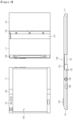
- FIG. 1 is a view illustrating an example of an appearance of an electronic device at various angles according to an embodiment of the present disclosure.
- FIG. 2 is a view illustrating an example of external appearances of front and rear surfaces of an electronic device according to an embodiment of the present disclosure.
- the electronic device 100 may schematically include a display 130 (e.g., a flexible display), a housing 110, and a hinge unit 120 (e.g., a hinge or a hinge part).
- a display 130 e.g., a flexible display
- a housing 110 e.g., a housing
- a hinge unit 120 e.g., a hinge or a hinge part
- the display 130 may include a flexible display, at least a portion of which is deflected (bent).
- the display 130 may include at least one pixel that may be deflected and signal lines.
- the display 130 may include a first display area 131, a second display area 132, and a hinge display area 133.
- the first display area 131, the hinge display area 133, and the second display area 132 may be connected to each other to form one entity.
- one side of the first display area 131 may be connected to one side of the hinge display area 133
- an opposite side of the hinge display area 133 may be connected to one side of the second display area 132.
- the first display area 131 may be disposed on a front surface of the display 130 or the second display area 132 may be disposed on a front surface of the display 130 according to a direction in which the display 130 is positioned.
- the first display area 131 and the second display area 132 may be disposed in directions that is opposite to each other.
- the hinge display area 133 may be observed from a side direction while being disposed between the first display area 131 and the second display area 132.
- the first display area 131, the hinge display area 133, and the second display area 132 may face the same direction with respect to the horizontal direction.
- the first display area 131 and the second display area 132 may face directions of different angles with respect to the horizontal direction.
- the size of the first display area 131 and the size of the second display area 132 may be the same or different.
- the drawing illustrates a form in which the size of the first display area 131 disposed in the first direction is smaller than the size of the second display area 132 disposed in the second direction (e.g., a direction that is opposite to the first direction) in the first state
- the present disclosure is not limited thereto.
- the first display area 131 and the second display area 132 may have the same size.
- the housing 110 may surround a periphery of the display 130 such that at least a partial area of the display 130 may be observed from the outside.
- Various device elements e.g., a driving circuit related to the display 130, an application processor, a printed circuit board, and a battery
- driving of the display 130 may be embedded inside the housing 110.
- Various elements related to a user function may be disposed on at least one side of the housing 110.
- the housing 110 may include a first housing 101 and a second housing 111 in correspondence to an area in which the display 130 is disposed.
- various device elements e.g., a driving circuit related to driving of the display 130, an application processor, a printed circuit board, and a battery
- driving circuit related to driving of the display 130 may be disposed in at least one of the first housing 101 and the second housing 111.
- the first housing 101 may include a first surface and a second surface that is opposite to the first surface, and may include three side surfaces disposed between the first surface and the second surface.
- One side surface of the hinge unit 120 may be disposed on one surface between the first surface and the second surface.
- a first display area of the display 130 for example, may be disposed on the first surface.
- the second housing 111 may include a third surface and a fourth surface that is opposite to the third surface, and may include three side surfaces disposed between the third surface and the fourth surface.
- An opposite side surface of the hinge unit 120 may be disposed on one surface between the third surface and the fourth surface. According to the state of the electronic device 100, the surfaces may have various disposition states.
- the first surface and the third surface or the second surface and the fourth surface may be disposed in the same direction.
- the first surface and the third surface are opposite to each other and the second surface and the fourth surface may face each other.
- the above-described electronic device 100 may be folded in an acute angle direction in which the second surface and the fourth surface face each other, and may be rotated to a parallel state (e.g., 180 degrees).
- the first display area 131 of the display 130 may be disposed over an overall central portion of the housing 101.
- a camera 103, a receiver 104, a sensor 105, and a home button 106 may be disposed in an area (e.g., a front area of an upper end or a front area of a lower end of the first display area 131) other than the first display area 131 of the first housing 101.
- a connector 107 may be disposed in one side surface area (e.g., an upper end side surface area or a lower end side surface area) of the first housing 101.
- a speaker hole 1011, a hold button 108, and an earphone connector 109 may be disposed in an opposite side surface area (e.g., a lower end side surface area) of the first housing 101.
- the first housing 101 may be connected to the second housing 111 through the hinge unit 120.
- the second display area 132 is disposed in the second housing 111, and the second housing 111 may surround a periphery of the second display area 132. At least some of the device elements related to driving of the display 130, for example, may be included inside the second housing 111. As illustrated, when the second display area 132 is larger than the first display area 131, in the first state, one side of a rear surface of the second housing 111 may be exposed in a direction of the first display area 131.
- An auxiliary display 139 for example, may be disposed on one side of a rear surface (e.g., one side of a periphery) of the second housing 111.
- An area of the auxiliary display 139 may include one or more virtual key buttons 114, 115a, 115b, 115c, and 115d.
- a power button 116 or a volume button 117 may be disposed in a side surface area of the second housing 111.
- the power button 116 or the volume button 117 may be disposed in a side surface area of the first housing 101.
- the hinge unit 120 may include a hinge shaft 125, a sliding unit 127, and a multi-bar 123.
- the hinge shaft 125 may fix the first housing 101 and the sliding unit 127 in a hinge manner.
- the hinge shaft 125 may support a hinge operation of the sliding unit 127 and the second housing 111 connected to the sliding unit 127 such that the sliding unit 127 is in a rotated state at a specific angle (e.g., 0 to 180 degrees) with respect to the first housing 101.
- the hinge shaft 125 may extend along a border between the first housing 101 and the second housing 111.
- the above-described hinge unit 120 may include a fifth surface and a sixth surface.
- the multi-bar 123 may be disposed on the fifth surface. At least a portion of the fifth surface may be curved or flat according to a hinge operation of the electronic device 100.
- the fifth surface may be disposed between the first surface and the third surface. According to an embodiment, the fifth surface may connect the first surface and the third surface. At least a portion of the display 130 may be disposed on the fifth surface.
- the sliding unit 127 may be disposed on the sixth surface, and at least a portion of the sliding unit 127 may be inserted in to the second housing 111 or may be extracted from the second housing 111 according to a hinge state of the electronic device 100.
- the sliding unit 127 may be disposed in a form in which at least a portion of the sliding unit 127 is moved to the outside of the second housing 111 and then at least a portion of the sliding unit 127 is extracted from the outside of the second housing 111.
- the sixth surface may be disposed between the second surface and the fourth surface.
- the multi-bar 123 may be disposed under the hinge display area 133 of the rear surface of the display 130.
- the multi-bar 123 may be continuously arranged in a flat form by an external force or may be bent at a specific angle.
- the sliding unit 127 may be slid into the second housing 111 or be exposed to the outside according to a folded state of the electronic device 100.
- the sliding unit 127 may maintain a state in which the sliding unit 127 is inserted into the second housing 111.
- the electronic device 100 is in the second state (e.g., an unfolded state)
- an area of the sliding unit 127 inserted into the second housing 111 may be minimized.
- a third state e.g., a state having a specific angle, for example, more than 0 to less than 180 degrees
- a partial area of the sliding unit 127 may be inserted into the second housing 111.
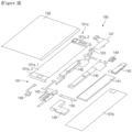
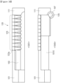
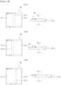
- FIG. 3 is a view schematically illustrating a first housing and a display of an electronic device according to an embodiment of the present disclosure.
- the first housing 101 of the present disclosure may include a right side upper end cover 101a and a right side rear surface case 101, and at least one of device elements, for example, a camera 103, a camera bracket 147, a receiver 144, an subscriber identification module (SIM) printed circuit board (PCB) 143, a battery 141, a main PCB 140, a shield can 145, a battery 141, a battery connection line 150, a connector case 149, a first sub PCB 142, a home button 148, and a battery connection line 150 may be embedded in the first housing 101.
- At least a portion of at least one of the device elements embedded in the first housing 101 may be exposed to the outside.
- at least a portion of the camera 103, the receiver 144, the connector case 149, and the home button 148 may be exposed through a hole provided in the right side upper end cover 101a.
- the camera bracket 147 may include a deck in which the camera 103 may be seated, and an image sensor configured to supply a signal to the camera 103 and store a signal acquired by the camera 103.
- the receiver 144 may output a communication connection sound or a communication sound of the electronic device 100.
- the SIM PCB 143 may include an SIM card, and may include a driving circuit related to reading and writing of the SIM card.
- the SIM PCB 143 may be electrically connected to the main PCB 140, and may provide SIM information in correspondence to control of an application process (or a processor) disposed in the main PCB 140.
- the battery 141 may supply electric power related to an operation of the electronic device 100.
- the battery 141 may be connected to a first sub PCB 142 through the battery connection line 150, and may be charged by receiving electric power from a charger connected to the outside through the connector case 149.
- the battery connection line 150 may be formed of a field programmable circuit board (or Flexible printed circuit board) (FPCB).
- the battery connection line 150 may connect the battery 141 and the first sub PCB 142.
- the first sub PCB 142 may be seated on one side of the connector case 149.
- a speaker and a microphone may be connected to the first sub PCB 142.
- the first sub PCB 142 may be connected to the main PCB 140 to transmit and receive a signal related the speaker and the microphone.
- One side of the home button 148 may be exposed through a hole provided in the right side upper end cover 101a.
- the home button 148 may be electrically connected to the first sub PCB 142 or may be directly connected to the main PCB 140.
- the right side upper end cover 101a may include a first seating part 101a_1 in which the first display area 131 of the display 130 may be disposed, a right side upper end area 101a_2 disposed at an upper end of the first seating part 101a_1, and a right side lower end area 101a_3 disposed at a lower end of the first seating part 101a_1.
- the camera 103, the receiver 144, and the like may be disposed in the right side upper end area 101a_2 of the right side upper end cover 101a.
- the home button 148, the connector case 149, and the like may be disposed in the right side lower end area 101a_3 of the right side upper end cover 101a.
- the above-described device elements disposed inside the first housing 101 is exemplary, and may be changed in correspondence of a design intention of the electronic device 100.
- the home button 148 has a form of a physical button, it may be replaced by a touch pad type.
- the camera 103 and the camera bracket 147 may be removed from the device elements.
- FIG. 4 is a view illustrating an example of a second housing according to an embodiment of the present disclosure.
- the second housing 111 of the present disclosure may include a left side upper end cover 111a and a left side rear surface case 111b.
- the second housing 111 may include a slide sheet 183, a bottom case 184, a bonding member 181, an auxiliary battery 186, first magnet members 182, an auxiliary display 139, a slide sheet 183, a side button 190 (e.g., the power button 116 or the volume button 117), and a slider 185.
- the second housing 111 may include a vibration module 187, antenna sheet 188, and a second sub PCB 189 electrically connected to the side button 190 and the auxiliary display 139 and configured to process a signal related to operations of the side button 190 and the auxiliary display 139.
- the left side upper end cover 111a may include a second seating part 111a_1 in which one surface of the display may be disposed, and a left side upper end area 111a_2 and a left side lower end area 111a_3 disposed at an upper end and a lower end of the second seating part 111a_1, respectively.
- the second seating part 111a_1 may include a flat area in which a central part of the second display area 132 is disposed, and a curved area in which a peripheral area of the second display area 132 is disposed.
- the display 130 may move to a partial area disposed in the curved area in correspondence to the bending of the electronic device 100.
- the display 130 may move from a periphery of the curved area of the second seating part 111a_1 toward a flat area by a specific length.
- the display 130 may move toward a periphery of the curved area of the second seating part 111a_1.
- At least a portion of the interiors of the left side upper end area 111a_2 and the left side lower end area 111a_3, for example, may be empty such that the second housing 111 moves in a specific direction with respect to the hinge unit 120.
- the hinge unit 120 may be provided inside the left side upper end area 111a_2 and the left side lower end area 111a_3, and rail supports 164 configured to support sliding of the second housing 111 may be moved.
- the slide sheet 183 may reduce a frictional force that may be repeatedly generated while the second housing 111 is slid while improving a sliding function of the second housing 111.
- the slide sheet 183 for example, may be formed of a material, a frictional coefficient of at least a portion of a surface of which is relatively low (or not more than a specific value).
- the bottom case 184 may be disposed inside the left side lower end area 111a_3 (or the left side upper end area 111a_2), and may guide a rail support 164 of the hinge unit 120.
- the bonding member 181 may bond the left side upper end cover 111a and the left side rear surface case 111b.
- the bonding member 181 may bond a peripheral part of the left side upper end cover 111a and a peripheral part of the left side rear surface case 111b.
- the auxiliary battery 186 may supply electric power of the electronic device 100.
- the auxiliary battery 186 may be charged in correspondence to control of a processor or be charged in parallel (or together with or simultaneously with) the battery 141 after the battery 141 disposed in the first housing 101 is completely charged.
- the first magnet member 182 may be used to maintain the first state (e.g., a folded state) of the electronic device 100.
- the auxiliary display 139 may be disposed at a periphery (e.g., under a curved area) of the left side upper end cover 111a, and may output information in correspondence of control to the processor.
- the auxiliary display 139 may include a touch screen function, and may be used as an input unit based on the touch screen function.
- the antenna sheet 188 may perform wireless charging or a near field communication (NFC) function.
- NFC near field communication
- the side button 190 may include a volume key or a power key.
- the vibration module 187 e.g., the vibration motor
- the second sub PCB 189 may perform signal processing related to control of the auxiliary display 139. Further, the second sub PCB 189 may process a user input by pressing of the side button 190 or may deliver the received user input to the main PCB 140.
- the slider 185 may be coupled to a constraint part of the rail support disposed in the hinge unit 120, and may fix the constraint part in the interior of the left side upper end area 111a_2 or the left side lower end area 111a_3 that performs sliding of the second housing 111. Accordingly, while the constraint part of the hinge unit 120 moves in the rail support, a sliding operation in which the second housing 111 becomes far away from or closer to the hinge unit 120 may be performed. Meanwhile, as an example, at least some of the above-described device elements included in the second housing 111 may be omitted or various other elements may be disposed in the second housing 111.
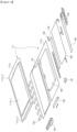
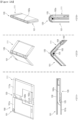
- FIG. 5 is a view illustrating an example of a hinge unit according to an embodiment of the present disclosure.
- FIG. 6 is an example of an exploded perspective view of a hinge unit according to an embodiment of the present disclosure.
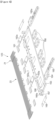
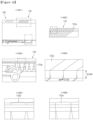
- FIG. 7 is a view illustrating an example of front and rear surfaces of a multi-bar according to an embodiment of the present disclosure.
- FIG. 8 is a view illustrating a partial area of a multi-bar according to an embodiment of the present disclosure.
- FIG. 9 is a view illustrating a coupled state of a multi-bar and a hinge bracket according to an embodiment of the present disclosure.
- FIG. 10 is a view illustrating an example of a portion of a side surface of an electronic device according to an embodiment of the present disclosure.
- the hinge unit 120 of the present disclosure may include at least one of a multi-bar 123, second magnet members 161, magnet support members 168, a plate 166, a support cover 163, rail supports 164, a constraint part 165, a hinge bracket 162a, a rotation guide 162b, and a support plate 169.
- the hinge unit 120 having the structure may be designed such that the center of the hinge unit 120 is branched (or at least a portion of the hinge unit 120 is separated).
- a pair of magnet support members 168 may be provided with respect to contacting surfaces thereof, and one of the pair of magnet support members 168 may be fixed to the plate 166 and the other of the pair of magnet support members 168 may be fixed to the support cover 163.
- the pair of second magnet members 161 may be disposed inside the magnet support members 168, respectively. Accordingly, one of the second magnet members 161 may be disposed on one side of the magnet support members 168, and the other of the second magnet members 161 may be disposed on an opposite side of the magnet support members 168.
- the magnet support members 168 and the second magnet members 161 may be spaced apart from each other to be disposed vertically in parallel to each other.
- the magnet support members 168 and the second magnet members 161 may be coupled to each other through a magnetic force while facing each other.
- the second magnet members 161 may include a plurality of magnets that form pairs. Further, the second magnet members 161 may form pairs, and at least first ones of the second magnet members 161 includes a magnet and the other ones of the second magnet members 161 may include a magnetic body reacting a magnetic force of the magnet.
- the pairs of second magnet members 161 may be disposed in the magnet support members 168 that form pairs.
- the second magnet members 161 may have a bar shape, the present disclosure is not limited thereto.
- the second magnet members 161 may have a shape such as a cylindrical shape or a polygonal shape.
- At least corresponding surfaces of the magnet support members 168 contact each other.
- the second magnet members 161 may be fixed to at least corresponding sides of the magnet support members 168.
- first ones of the second magnet members 161 is inserted into first ones of the magnet support members 168 that form pairs, and surfaces of the second magnet members 161 may be exposed to the outside.
- the other ones of the magnet support members 168 that form pairs also may be inserted into the other ones of the second magnet members 161, and surfaces of the inserted second magnet members 161 may be exposed to face the other ones.
- the magnet support members 168 that form pairs may be fixed to the plate 166 and the support cover 163, respectively, and the facing surfaces of the magnet support members 168 may contact each other or be spaced apart from each other in correspondence to spacing or arrangement of the plate 166 and the support cover 163. As the pair of magnet support members 168 are separated or integrated, the pairs of the second magnet members 161 fixed to one side of the magnet support members 168 may be separated or be coupled to each other (or maintain a contact state) based on a magnetic force.
- the plate 166 may be disposed axially while having a specific length (e.g., a length that is the same as or similar to a longitudinal length of the electronic device 100).
- At least one first connector 166a e.g., a boss having a female screw thread
- First ones of the magnetic support members 168 that form pairs may be fixed to the first connector 166a disposed in the plate 166
- first ones of the second magnet members 161 that form pairs may be fixed to the magnet support members 168.
- at least one hinge bracket 162a (e.g., some hinge brackets 162a) may be fixed to one side of the plate 166.
- the plate 166 may be disposed in parallel to the support cover 163.
- the support cover 163 may have a specific axial length (e.g., a length that is substantially the same as that of the plate 166) and a specific width (e.g., a specific width that is larger than that of the plate 166).
- At least one second connector 163a e.g., a boss having a female screw thread
- the second connector 163a disposed in the support cover 163 may be disposed to be aligned with the first connector 166a disposed in the plate 166.
- First ones of the magnet support members 168 that form pairs may be fixed to an upper side of the support cover 163.
- the rail supports 164 may be fixed to one side of the support cover 163.
- the support plate 169 may be disposed between the support cover 163 and the rail supports 164.
- the support cover 163 When the electronic device 100 is in a second state (e.g., an unfolded state), the support cover 163 may be disposed in parallel to the plate 166. Further, when the electronic device 100 is in a first state (e.g., a folded state), the support cover 163 may be aligned with the plate 166 vertically.
- the support cover 163 may include a seating groove 167 in which the hinge shaft 125 may be seated, at a periphery of one side of the support cover 163.
- the seating groove 167 may extend in a longitudinal direction of the support cover 163.
- the hinge shaft 125 inserted into the seating groove 167 may be rotated in the seating groove 167 by magnet support members and a hinge bracket.
- the rail supports 164 may be disposed on one side (e.g., an upper end side and a lower end side) of the support cover 163. Some of the rail supports 164 may have shapes that are similar to those of the magnet support members 168, and the others of the rail supports may have a ring shape one axis of which is relatively longer than the other axis thereof. The ring may be disposed in a direction of the second housing 111.
- the constraint part 165 may be disposed on one side (e.g., an inside of the ring) of the rail supports 164.
- the constraint part 165 may have an elliptical shape, one axis of which is longer than another axis thereof, or a rectangular shape, a corner of which is rounded.
- the constraint part 165 may be disposed inside the rings of the rail supports 164. Then, the constraint part 165 may move in one direction (e.g., a long axis direction of the ring) inside the rail supports 164.
- the constraint part 165 for example may be fixed to one side of the second housing 111. Accordingly, as the second housing 111 moves while the electronic device 100 is in the first state or in the second state, the constraint part 165 may move to leftwards and rightwards (or forwards and rearwards) inside the rain supports 164.
- the constraint part 165 may include at least one third connector 165a (e.g., a hole having a female screw thread) for coupling with the second housing 111.
- the hinge bracket 162a may have a rectangular shape, and one end of the hinge bracket 162a may be bent and the remaining areas of the hinge bracket 162a may be flat. At least one fourth connector 162a_1 (e.g., a hole having a female screw thread), which is to be coupled to the plate 166 or the support cover 163 may be disposed on one side of the hinge bracket 162a.
- a plurality of hinge brackets 162a may be provided. Some of the plurality of hinge brackets 162a may be coupled to the plate 166, and the remaining ones thereof may be coupled to the support cover 163.
- the hinge brackets 162a may function to fix the multi-bar 123 while the electronic device 100 is in the first state or the second state. In this regard, the hinge brackets 162a may be inserted into recesses formed in the multi-bar 123.
- the rotation guide 162b may include a flat area, and a curved area extending from the flat area.
- the flat area may include at least one fixing hole that may fix the rotation guide 162b to the plate 166.
- a section of an end of the curved area of the rotation guide 162b may face a front surface of the support cover 163 while the electronic device 100 is unfolded state.
- the above-described rotation guide 162b may support rotation of the multi-bar 123 while the state of the electronic device 100 is changed to a bent state (e.g., a state in which the first housing 101 and the second housing 111 form a specific angle, for example, 30 degrees, 60 degrees, 90 degrees, or 120 degrees) or a folded state (a state in which the first housing 101 and the second housing 111 are disposed vertically in parallel to each other or a state in which an angle formed by the first housing 101 and the second housing 111 is 0 degrees).
- a bent state e.g., a state in which the first housing 101 and the second housing 111 form a specific angle, for example, 30 degrees, 60 degrees, 90 degrees, or 120 degrees
- a folded state a state in which the first housing 101 and the second housing 111 are disposed vertically in parallel to each other or a state in which an angle formed by the first housing 101 and the second housing 111 is 0 degrees.
- the support plate 169 may have a rectangular shape, and may be disposed between the support cover 163 and the rail supports 164 to support the rail supports 164. According to an embodiment, the support plate 169 may support the constraint part 165 when the constraint part 165 moves as the second housing 111 rotates while facing one surface of the constraint part 165 disposed inside the rail supports 164 under the constraint part 165.
- At least a portion of an upper surface of the multi-bar 123 in the axial direction of the hinge unit 120 may be flat and a plurality of columns stepped between a central portion and a peripheral portion of the multi-bar 123 may be mechanically coupled to each other.
- a rear surface of the display 130 may be seated in a central bottom part 23 of an upper surface (e.g., a surface in a direction in which the display 130 is disposed) of the multi-bar 123, and a peripheral part and the stepped part 21 of the multi-bar 123 may protect a side surface of the display 130 and guide a side surface of the display 130 when the display is slid.
- the electronic device 100 may support the second state (e.g., the unfolded state) more firmly based on the magnetic coupling or separation of the second magnet members 161 that form pairs.
- the multi-bar 123 may be provided such that the plurality of columns 123a are continuously connected to each other.
- a portion of an upper part of one column 123a of the multi-bar 123 for example, at least a portion of an upper end of the bottom part 23 of the multi-bar 123 may be formed flat, and stepped parts 21 that are higher than the bottom part 23 by a specific height may be disposed at opposite ends of the central portion of the multi-bar 123.
- a lower portion of the column 123a may include one or more bosses 25 extending downwards. The bosses 25 may be spaced apart from each other at a specific interval.
- Conic downward bosses for example, triangular bosses 27 (or polygonal bosses) may be disposed in the stepped parts 21 of the opposite ends of the column 123a.
- the triangular bosses 27 may function as a shield such that the inside of the electronic device 100 is not observed from the outside while contacting (continuously contacting) the triangular bosses 27 of the adjacent columns.
- the column 123a may include one or more connection bosses 29 extending from one or more side walls of the bosses 25 at angles that are different from those of the bosses 25.
- the column 123a may include one or more boss recesses 28 disposed on a surface of the column 123a, which is opposite to a surface on which the bosses 25 having the connection bosses 29 are formed, and into which the connection bosses 29 may be inserted.
- the connection bosses of another column may be inserted into the boss recesses 28 or at least some of the connection bosses of another column may be extracted from the boss recesses 28 according to whether the electronic device 100 is folded.
- the multi-bar 123 in which a plurality of columns 123a are continuously disposed may include a groove 901 having a specific length as the above-described bosses 25 are continuously disposed with respect to a horizontal surface.
- the above-mentioned hinge bracket 162a may be inserted into the groove 901.
- the hinge bracket 162a inserted into the groove 901 may support the columns of the multi-bar 123 while moving along an inner wall of the groove 901 in correspondence to whether the electronic device 100 is folded or unfolded.
- the shape of the multi-bar 123 may be maintained by fixing the columns 123a of the hinge bracket 162a such that the columns 123a are not separated.
- the groove 901 may have a specific shape (e.g., a T shape) such that the hinge bracket 162a is not easily separated after being inserted into the groove 901.
- the hinge bracket 162a may have a shape (e.g., a T shape), an upper end of which has a width that is larger than that of a lower end thereof.
- the second housing 111 of the electronic device 100 may be connected to the hinge unit 120.
- the hinge unit 120 for example, the plurality of columns 123a are continuously arranged, and the upper end surfaces of the columns 123a may be continuously disposed in correspondence to the unfolded state of the electronic device 100. Accordingly, lower ends of the columns 123a, a section of a lower end of which is smaller than that of an upper end thereof (for example, the section is triangular), may be disposed in a convexo-concave form as in state 1001.
- the hinge unit 120 may include a side cover 1010 as in state 1005.
- the side cover 1010 coupled to the hinge unit 120 may be inserted into the second housing 111 by a first width (e.g., a width inserted into the second housing 111 in a folded state) or by a second width (e.g., a width inserted into the second housing 111 in an unfolded state) according to the folded state or the unfolded state of the electronic device 100.
- a first width e.g., a width inserted into the second housing 111 in a folded state
- a second width e.g., a width inserted into the second housing 111 in an unfolded state
- An opposite side of the hinge unit 120 may be connected to the housing 101.
- the hinge shaft 125 may be disposed on one side of the first housing 101.
- the hinge unit 120 may be rotated about the hinge shaft 125 inserted into the seating groove 167 while performing a hinge operation, and the second housing 111 connected to an end of the hinge unit 120 may be disposed at a specific angle according to rotation of the hinge unit 120.
- the support cover 163 provided in the hinge unit 120 and the side cover 1010 supporting a side surface of the hinge unit 120 may performing a sliding operation to the inside of the second housing 111.
- FIG. 11 is a view illustrating an example of a coupled state of an electronic device according to an embodiment of the present disclosure.
- FIG. 12a is a view exemplifying a coupling sequence of an electronic device according to an embodiment of the present disclosure.
- the electronic device 100 may include a first housing 101, a second housing 111, and a hinge unit 120.
- the first housing 101 may be disposed such that the first display area of the display is exposed, and at least one device element related to driving of the electronic device 100 may be disposed.
- the device element disposed inside the first housing 101 may include at least one of a battery, a microphone, a camera, a memory, an SIM card, a first magnet member for coupling, a speaker, a connector, and an ear jack connector.
- the device element disposed inside the second housing 111 for example, may include an auxiliary battery, a vibration module, a magnet member for coupling, and a side button.
- the right side upper end cover 101a of the first housing 101 and the left side upper end cover 111a of the second housing 111 may be disposed in parallel to each other, and the hinge unit 120 may be coupled between the right side upper end cover 101a and the left side upper end cover 111a.
- the above-described device elements disposed inside the first housing 101 may be disposed inside the right side upper end cover 101a
- the above-described device elements disposed inside the second housing 111 may be disposed inside the left side upper end cover 111a.
- the display 130 may be disposed on a front surface of the electronic device 100.
- seating surfaces on which the display 130 may be seated, may be disposed at central portions of the right side upper end cover 101a of the first housing 101 and the left side upper end cover 111a of the second housing 111.
- a surface of the hinge unit 120, on which the display 130 is positioned, may have a downwardly stepped shape, a specific area recess (e.g., areas of the bottom parts of the centers of the columns 123a) corresponding to the seating surface is lower than opposite ends thereof.
- one flexible display 130 may be disposed on the right side upper end cover 101a, a bottom part of the center of the upper end of the hinge unit 120, and the left side upper end cover 111a.
- the display 130 may be electrically connected to the main cover disposed inside the right side upper end cover 101a through a hole disposed on one side of the right side upper end cover 101a.
- the right side rear surface case 101b and the left side rear surface case 111b of the electronic device 100 may cover the rear surfaces of the right side upper end cover 101a and the left side upper end cover 111a. Then, the left side upper end cover 111a and the left side rear surface case 111b may be coupled to each other such that the rail supports 164 disposed in the hinge unit 120 may be slid.
- FIG. 12b is a view illustrating an example of a state of an internal structure during a hinge operation of an electronic device according to an embodiment of the present disclosure.
- the electronic device 100 may be in an unfolded state.
- the first housing 101, the second housing 111, and the hinge unit 120 of the electronic device 100 may be parallel to each other.
- a flat area of the hinge bracket 162a may be disposed in parallel to the front surface of the first housing 101.
- the rotation guide 162b may support the unfolded state of the plate and the support cover.
- the hinge shaft 125 may be disposed between the right side rear surface case 101b of the first housing 101 and the hinge unit 120.
- the hinge shaft 125 may have a semicircular section such that it does not protrude to the outside or a protrusion degree thereof is small, and the protruding portion of the hinge shaft 125 may be disposed from the right side rear surface case 101b toward the right side upper end cover 101a of the first housing 101.
- the multi-bar 123 When the electronic device 100 is in an unfolded state, the multi-bar 123 may be disposed in a horizontal state.
- the drawing illustrates an area of a central portion of the display 130 is cut, for description of the hinge unit 120.
- the electronic device 100 may have a bent state in which the first housing 101 and the second housing 111 form a specific angle.
- the flat area of the hinge bracket 162a disposed in the hinge unit 120 may form a specific angle with an upper end surface of the second housing 111 while being disposed in parallel to the upper end surface of the second housing 111.
- the electronic device 100 is in a bent state, at least a portion of the multi-bar 123 of the hinge unit 120 may be bent.
- the support cover 163 of the hinge unit 120 may be slid into the second housing 111. Further, the rail supports 164 of the hinge unit 120 may be slid along the constraint part 165 as an axis.
- the electronic device 100 may have a folded state in which the first housing 101 and the second housing 111 are disposed in parallel to each other.
- the rear surface of the first housing 101 may face the rear surface of the hinge unit 120 and the rear surface of the second housing 111 with respect to the hinge shaft 125.
- a flat area of the hinge bracket 162a may be disposed in parallel to the upper end surface of the first housing 101.
- FIG. 13 is a view illustrating various examples of a hold state of an electronic device according to an embodiment of the present disclosure.
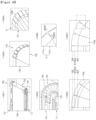
- FIG. 14 is a view illustrating an example of a state of a hinge unit in an unfolded state of an electronic device according to an embodiment of the present disclosure.
- FIG. 15 is a view illustrating an example of a state of a hinge unit in a bent state of an electronic device according to an embodiment of the present disclosure.
- FIG. 16 is a view illustrating an example of a state of a hinge unit in a folded state of an electronic device according to an embodiment of the present disclosure.
- the electronic device 100 of the present disclosure may be in an unfolded state.
- the unfolded state may include a state in which the first housing 101, the hinge unit 120, and the second housing 111 are disposed in parallel to each other.
- upper surfaces of the columns 123a may contact upper surface of the adjacent columns.
- the upper end surface of the multi-bar 123 may be flat, and the display 130 may be disposed on the flat surface to be flat. While the upper surfaces of the columns 123a having an inverse triangular section is flat, a lower portion of the multi-bar 123 may be convexo-concave.
- the electronic device 100 may be in a bent state as in state 1303.
- the drawing illustrates a state in which the first housing 101 and the second housing 111 form an angle of 90 degrees
- the present disclosure is not limited thereto.
- at least one bars of the multi-bar 123 of the hinge unit 120 are disposed such that there is no convexo-concave gap and the remaining bars of the multi-bar 123 may be disposed to maintain a convexo-concave gap.
- lower sides of the first columns 123a_1 of the multi-bar 123 disposed in parallel to the second housing 111 may maintain a convexo-concave shape while the upper surfaces thereof are flat.
- the lower inclined edges of the second columns 123a_2 disposed in bent areas of the multi-bar 123 may face inclined edges of the adjacent columns. Accordingly, while the upper surfaces of the bars of the multi-bar 123 maintain a flat shape, the lower sides of the bars of the multi-bar 123 may be adjacent to each other or may gather together with respect to the hinge shaft 125. Accordingly, the display 130 may include an area disposed on the first housing 101 to be flat, an area disposed in the first housing 101 to be flat while forming a specific angle (e.g., the right angle), and a curved area (a shape of a 1/4 arc of a circle) disposed on the hinge unit 120.
- a specific angle e.g., the right angle
- a curved area a shape of a 1/4 arc of a circle
- the electronic device 100 may be in a folded state as in state 1305.
- a first housing 101 and a second housing 111 may be disposed in parallel to each other. Then, a rear surface of the first housing 101 and a rear surface of the second housing 111 may face each other.
- the multi-bar 123 of the hinge unit 120 may be disposed in a semicircular shape (or at 180 degrees with respect to the hinge shaft 125).
- the multi-bar 123 disposed in a semicircular shape may have a state in which the lower inclined edges of the columns 123a contact or face the lower inclined edges of the adjacent columns. Further, the apexes of the columns 123a of the multi-bar 123 may gather in the hinge shaft 125.
- the display 130 may be disposed at an upper portion of the multi-bar to be deflected in correspondence to the bent shape of the multi-bar 123. Accordingly, the display 130 may include an area disposed on the first housing 101 to be flat, an area disposed in the first housing 101 to be flat while being disposed in parallel to the first housing 101, and a curved area (a shape of a semicircle of a circle) disposed on the hinge unit 120. It is noted that the columns 123a may have shapes other than a convexo-concave shape, and thus are not limited thereto.
- the columns 123a may be cubic or cylindrical in shape, with or without hollow interiors, (not shown) if the columns 123a are made of a resiliently-compressible material that can be compressed in shape to, e.g., a convexo-concave shape, as the first housing 101 and/or the second housing 111 is/are rotated around the hinge shaft 125 similar to 123_1 in state 1303 illustrated in FIG. 13 .
- the electronic device 100 may have a form in which the multi-bar 123 disposed in the hinge unit 120 is disposed to be flat.
- the hinge unit 120 is disposed such that the plurality of columns 123a constituting the multi-bar 123 are parallel to each other while forming a flat surface and surface-contacting each other as in state 1402.
- the lower sides of the columns 123a constituting the hinge unit 120 may have a saw-tooth shape (or a convexo-concave shape).
- the upper sides of the columns 123a may have an upwardly stepped shape.
- an aperture may not be generated between the stepped parts disposed at the outskirts of the columns 123a while being closely adjacent to the stepped parts of the adjacent columns.
- the bottom parts disposed inside the columns 123a may be disposed in parallel to the bottom parts of the adjacent columns, and may be disposed while having a specific interval (e.g., S103).
- the steps between the stepped parts and the bottom parts may have a height corresponding to the thickness (e.g., S104) of the display. Further, the height of the steps may have a value that is larger than the thickness of the display 130 to protect the display 130.
- the electronic device 100 may have a form in which the multi-bar 123 disposed in the hinge unit 120 has a specific bending angle (e.g., 30 to 120 degrees, for example, 90 degrees).
- a specific bending angle e.g. 30 to 120 degrees, for example, 90 degrees.
- some first columns 123a_1 of the plurality of columns 123a constituting the multi-bar 123 of the hinge unit 120 disposed between the first housing 101 and the second housing 111 may be disposed to form curved surfaces and the remaining second columns 123a_2 may form flat surfaces.
- the display 130 may be in a bent state.
- the disposition state of the plurality of columns 123a constituting the multi-bar 123 may be changed.
- the first column parts 123a_1 forming curved surfaces may be disposed to be adjacent to the other columns while having a specific interval between the stepped parts 21.
- the bottom parts 23 of the first columns 123a_1 forming curved surfaces may be disposed to closely contact the bottom parts of the adjacent columns such that no separate aperture is generated.
- the lower side walls of the first columns 123a_1 forming curved surfaces may be disposed to closely contact the lower side walls of the adjacent columns.
- the stepped parts 21 of the second columns 123a_2 forming flat surfaces may be disposed to be close to the stepped parts of the adjacent columns substantially without having no apertures.
- the bottom parts 23 of the second columns 123a_2 forming flat surfaces may be disposed in parallel to the bottom parts of the adjacent columns while having a specific gap with the bottom parts of the adjacent columns.
- the lower side walls of the second columns 123a_2 forming flat surfaces may be disposed while forming a saw-tooth shape (or a convexo-concave shape).
- the electronic device 100 may be disposed such that the first housing 101 and the second housing 111 are folded.
- the upper ends of the plurality of columns 123a constituting the multi-bar 123 included in the hinge unit 120 may form curved surfaces (for example, semicircular surfaces).
- the lower side walls of the columns 123a having an inverse-triangular section may be disposed while being closely adjacent to or contacting the lower side walls of the adjacent columns.
- the center lines of the columns 123a for example, may face the center of the hinge shaft 125.
- the stepped parts 21 of the plurality of columns 123a constituting the multi-bar 123 disposed in the hinge unit 120 may be widened while having a specific interval from the stepped parts of the adjacent columns.
- the bottom parts 23 of the columns 123a may closely contact the bottom parts of the adjacent columns.
- each of the upper ends of the columns 123a may include an outer stepped portion 21a widened while forming a specific angle, and an inner stepped portion 21b having no aperture while closely contacting the adjacent columns.
- the outer stepped portions 21a and the inner stepped portions 21b are provided to separate the upper ends of the columns in view of meanings, and may be provided as a single body.
- a location of a neutral surface of the display 130 may be determined in consideration of the thickness and material of the display 130, and the neutral surface may correspond to a specific range from the top surface to the bottom surface of the display 130.
- the angle of area S002 increases while the size of area S003 becomes zero, and a design having no aperture (or a gap) in a part that supports the display 130 may be maintained even when the electronic device is completely spread.
- the size of area S003 increases to the corresponding surface and the size of area S002 decreases when the neutral surface is applied with reference to the top surface and the apertures of the bottom surfaces of the columns 123a supporting the display are present to a degree when the electronic device is spread, but the degree of the apertures of the bottom surfaces may become smaller to an ignorable degree because the thickness of the display 130 is small.
- the apertures of the columns 123a supporting the display 130 is a specific distance (e.g., 0.1 mm) and the columns 123a exposed to the outside may surface-contact each other while having no aperture.
- FIG. 17 is a view illustrating an example of an inside of a hinge unit in a folded state of an electronic device according to an embodiment of the present disclosure.
- the hinge unit 120 of the electronic device 100 may be curved while the first housing 101 and the second housing 111 are disposed vertically in parallel to each other.
- the stepped parts 21 of the columns 123a included in the multi-bar 123 of the hinge unit 120 may be spaced apart from the stepped parts of the adjacent columns by a specific interval.
- the bottom parts 23 of the columns 123a may closely contact the bottom parts of the adjacent columns, and the columns 123a may be disposed circularly as a whole. In this state, the columns 123a may form curved parts with respect to the hinge shaft 125.
- the hinge unit 120 forms a curved portion
- the second magnet members 161 forming pairs, which are disposed in the hinge unit 120, and the magnet support members 168 including the second magnet members 161 may be disposed vertically in parallel to each other.
- First ones of the second magnet members 161 forming pairs and the magnet support members 168 forming pairs may be disposed in the plate 166, and the other ones thereof may be disposed in the support cover 163.
- FIG. 18 is a view illustrating an example of various forms of an electronic device according to an embodiment of the present disclosure.
- a ratio of the first display area 131 and the second display area 132 may be a specific ratio (e.g., 5:5, 7:3, or 3:7).
- the sizes of the first display area 131_1 disposed in the first housing 101_1 and the second display area 132_1 disposed in the second housing 111_1 may be the same or similar. Accordingly, the first display area 131_1 and the second display area 132_1 may face each other while extending vertically at the same length while the hinge unit 120_1 forms a curved portion such that the electronic device 100 is in a folded state.
- a hinge display area 133_1 may be disposed between the first display area 131_1 and the second display area 132_1. The hinge display area 133_1 may be disposed on the hinge unit 120_1.
- the size of the first display area 131_2 disposed in the first housing 101_2 may be smaller than the second display area 132_2 disposed in the second housing 111_2.
- a hinge display area 133_2 disposed on the hinge unit 120_2 may be disposed between the first display area 131_2 and the second display area 133_2.
- auxiliary display 139 may be disposed in a partial area of the second display area 132_2 exposed to the outside.
- a physical key pressure sensor, a display touch sensor, and the like may be disposed in an area in which the auxiliary display 139 is disposed.
- a side key may be disposed at a side of the first housing 101_2 or a side of the second housing 111_2.
- the size of the first display area 131_3 disposed in the first housing 101_3 may be larger than the second display area 132_3 disposed in the second housing 111_3.
- a partial area of the first display area 131_3 may be exposed to the outside while the rear surface of the second display area 132_3 is positioned in a partial area of the rear surface of the first display area 131_3.
- a hinge display area 133_3 may be disposed on the hinge unit 120_3, between the first display area 131_3 and the second display area 132_3.
- the flexible display device may secure a utility when being folded and a utility when being unfolded.
- the hinge unit 120 may absorb a displacement that is necessary during a folding operation or an unfolding operation of the first housing 101 and the second housing 111.
- the flexible display device only the first display area 131 disposed in the first housing 101 or the second display area 132 disposed in the second housing 111 may be turned on in the folded state of the flexible display device.
- a display area e.g., the first display area 131 of the flexible display device in a direction of the front surface of the flexible display device may be turned on.
- the second display area 132 may be turned on or the first display area 131 and the second display area 132 may be turned on.
- the hinge display area 133 disposed in an area of the hinge unit 120 may maintain a turn-off state.
- the display 130 e.g., the first display area 131, the second display area 132, and the hinge display area 133
- the display 130 may be automatically turned on.
- at least a portion of the display may be turned off (e.g., the entire display area may be turned off or the second display area 132 may be turned off).
- the portability of the display may be maintained while the size of the display is enlarged.
- the display areas may be used in various forms according to a folded state of the flexible display device, and a folding fatigue of the display, which occurs in a section that is folded by a hinge operation, may be improved.
Landscapes
- Engineering & Computer Science (AREA)
- Theoretical Computer Science (AREA)
- Computer Hardware Design (AREA)
- Physics & Mathematics (AREA)
- General Physics & Mathematics (AREA)
- Human Computer Interaction (AREA)
- General Engineering & Computer Science (AREA)
- Microelectronics & Electronic Packaging (AREA)
- Mathematical Physics (AREA)
- Signal Processing (AREA)
- Telephone Set Structure (AREA)
- Casings For Electric Apparatus (AREA)
- Devices For Indicating Variable Information By Combining Individual Elements (AREA)
- Nonlinear Science (AREA)
- Chemical & Material Sciences (AREA)
- Crystallography & Structural Chemistry (AREA)
- Optics & Photonics (AREA)
Claims (5)
- Tragbare Kommunikationsvorrichtung (100), umfassend:ein erstes Gehäuse (101), das eine erste Oberfläche und eine zweite Oberfläche gegenüber der ersten Oberfläche umfasst;ein zweites Gehäuse (111), das kleiner als das erste Gehäuse ist, wobei das zweite Gehäuse eine dritte Oberfläche und eine vierte Oberfläche gegenüber der dritten Oberfläche umfasst;eine Scharniereinheit (120), die eine Scharnierwelle (125), eine Schiebeeinheit (127), eine Mehrfachstange (123), Schienenstützen (164) und Beschränkungsteile (165) einschließt, wobei die Scharniereinheit dazu konfiguriert ist, eine Drehung des ersten Gehäuses relativ zu dem zweiten Gehäuse in einem Scharniervorgang derart zu ermöglichen, dass die zweite Oberfläche des ersten Gehäuses der vierten Oberfläche des zweiten Gehäuses zugewandt ist, falls die tragbare Kommunikationsvorrichtung zugeklappt ist;eine flexible Anzeige (130), umfassend eine erste Anzeigefläche (131), die über der ersten Oberfläche angeordnet ist, eine zweite Anzeigefläche (132), die über der dritten Oberfläche angeordnet ist, und eine Scharnieranzeigefläche (133), die an der Scharniereinheit angeordnet und zwischen der ersten Anzeigefläche und der zweiten Anzeigefläche positioniert ist;wobei:die Scharnierwelle (125) das erste Gehäuse (101) und die Schiebeeinheit (127) auf Scharnierweise fixiert;die Schiebeeinheit (127) dazu konfiguriert ist, gemäß einem zugeklappten Zustand der tragbaren Kommunikationsvorrichtung (100) in das zweite Gehäuse (111) eingesetzt oder aus dem zweiten Gehäuse (111) herausgezogen zu werden,die Schienenstützen mit der Schiebeeinheit fixiert sind und dazu konfiguriert sind, ein Verschieben des zweiten Gehäuses zu unterstützen,wobei die Schienenstützen (164) Ringe umfassen, von denen eine Achse relativ länger als die andere Achse davon ist, wobei die längere Achse in einer Richtung des zweiten Gehäuses angeordnet ist;die ein Beschränkungsteile (165) an dem zweiten Gehäuse fixiert sind und jeweils innerhalb der Ringe der Schienenstützen angeordnet sind und dazu konfiguriert sind, sich innerhalb der Ringe der Schienenstützen derart entlang der Längsachsenrichtungen zu bewegen, dass die Schienenstützen entlang der Beschränkungsteile als Achse verschiebbar sind, um ein Verschieben des zweiten Gehäuses zu unterstützen,und die Mehrfachstange (123) Folgendes einschließt:eine Vielzahl von Säulen (123a), die zwischen einem zentralen unteren Teil (23) und einem peripheren Teil (21) der Mehrfachstange (123) gestuft ist,wobei eine hintere Oberfläche der flexiblen Anzeige (130) dazu konfiguriert ist, in dem zentralen unteren Teil (23) einer oberen Oberfläche der Mehrfachstange (123) zu sitzen, und das periphere Teil und das gestufte Teil (21) der Mehrfachstange (123) dazu konfiguriert sind, eine Seitenoberfläche der flexiblen Anzeige (130) zu schützen und eine Seitenoberfläche der flexiblen Anzeige (130) zu führen, wenn die flexible Anzeige während der Drehung des ersten Gehäuses relativ zu dem zweiten Gehäuse in dem Scharniervorgang verschoben wird; undwobei jede der Säulen eine obere Oberfläche, die der flexiblen Anzeige zugewandt ist, und eine untere Oberfläche, die der oberen Oberfläche gegenüberliegt, umfasst und wobei eine Breite der unteren Oberfläche kleiner als die Breite der oberen Oberfläche ist.
- Tragbare Kommunikationsvorrichtung nach Anspruch 1, wobei die erste Anzeigefläche größer ist als die zweite Anzeigefläche.
- Tragbare Kommunikationsvorrichtung nach Anspruch 1, ferner umfassend eine Kamera (103), wobei in Verwendung, falls eine Fotografieranwendung ausgeführt wird, wenn sich die Vorrichtung in einem zugeklappten Zustand befindet, die Scharnieranzeigefläche dazu konfiguriert ist, ausgeschaltet zu sein, während die erste Anzeigefläche und/oder die zweite Anzeige dazu konfiguriert sind, eingeschaltet zu sein.
- Tragbare Kommunikationsvorrichtung nach Anspruch 3, wobei in Verwendung, falls der Zustand der Vorrichtung von einem zugeklappten Zustand zu einem aufgeklappten Zustand geändert wird, die erste Anzeigefläche, die zweite Anzeigefläche und die Scharnieranzeigefläche dazu konfiguriert sind, eingeschaltet zu sein.
- Tragbare Kommunikationsvorrichtung nach Anspruch 1, wobei die Säulen dazu konfiguriert sind, eine gekrümmte obere Oberfläche zu beschreiben, die der flexiblen Anzeige zugewandt ist, wenn sich die Vorrichtung in einem zugeklappten Zustand befindet.
Applications Claiming Priority (3)
| Application Number | Priority Date | Filing Date | Title |
|---|---|---|---|
| KR1020160117854A KR102636648B1 (ko) | 2016-09-13 | 2016-09-13 | 플렉서블 디스플레이 전자 장치 |
| EP17851069.9A EP3472822B1 (de) | 2016-09-13 | 2017-08-03 | Elektronische vorrichtung mit einer flexiblen anzeige |
| PCT/KR2017/008421 WO2018052192A1 (en) | 2016-09-13 | 2017-08-03 | Flexible display electronic device |
Related Parent Applications (2)
| Application Number | Title | Priority Date | Filing Date |
|---|---|---|---|
| EP17851069.9A Division EP3472822B1 (de) | 2016-09-13 | 2017-08-03 | Elektronische vorrichtung mit einer flexiblen anzeige |
| EP17851069.9A Division-Into EP3472822B1 (de) | 2016-09-13 | 2017-08-03 | Elektronische vorrichtung mit einer flexiblen anzeige |
Publications (3)
| Publication Number | Publication Date |
|---|---|
| EP4009140A1 EP4009140A1 (de) | 2022-06-08 |
| EP4009140B1 true EP4009140B1 (de) | 2025-06-18 |
| EP4009140C0 EP4009140C0 (de) | 2025-06-18 |
Family
ID=61561135
Family Applications (3)
| Application Number | Title | Priority Date | Filing Date |
|---|---|---|---|
| EP21170235.2A Active EP3872600B1 (de) | 2016-09-13 | 2017-08-03 | Aufklappbare, tragbare kommunikationsvorrichtung mit flexibler anzeige |
| EP17851069.9A Active EP3472822B1 (de) | 2016-09-13 | 2017-08-03 | Elektronische vorrichtung mit einer flexiblen anzeige |
| EP22152554.6A Active EP4009140B1 (de) | 2016-09-13 | 2017-08-03 | Elektronische vorrichtung mit einer flexiblen anzeige |
Family Applications Before (2)
| Application Number | Title | Priority Date | Filing Date |
|---|---|---|---|
| EP21170235.2A Active EP3872600B1 (de) | 2016-09-13 | 2017-08-03 | Aufklappbare, tragbare kommunikationsvorrichtung mit flexibler anzeige |
| EP17851069.9A Active EP3472822B1 (de) | 2016-09-13 | 2017-08-03 | Elektronische vorrichtung mit einer flexiblen anzeige |
Country Status (6)
| Country | Link |
|---|---|
| US (4) | US9992888B2 (de) |
| EP (3) | EP3872600B1 (de) |
| JP (2) | JP6833982B2 (de) |
| KR (2) | KR102636648B1 (de) |
| CN (3) | CN109690662B (de) |
| WO (1) | WO2018052192A1 (de) |
Families Citing this family (111)
| Publication number | Priority date | Publication date | Assignee | Title |
|---|---|---|---|---|
| US10132478B2 (en) * | 2016-03-06 | 2018-11-20 | Svv Technology Innovations, Inc. | Flexible solid-state illumination devices |
| KR20180121568A (ko) | 2016-03-09 | 2018-11-07 | 코닝 인코포레이티드 | 복합적으로 굽은 유리 제품의 냉간 형성 |
| WO2018005646A1 (en) | 2016-06-28 | 2018-01-04 | Corning Incorporated | Laminating thin strengthened glass to curved molded plastic surface for decorative and display cover application |
| WO2018009504A1 (en) | 2016-07-05 | 2018-01-11 | Corning Incorporated | Cold-formed glass article and assembly process thereof |
| KR102636648B1 (ko) * | 2016-09-13 | 2024-02-15 | 삼성전자주식회사 | 플렉서블 디스플레이 전자 장치 |
| CN107846484B (zh) * | 2016-09-20 | 2020-01-10 | 华为机器有限公司 | 一种移动终端的折叠机构及移动终端 |
| KR102631840B1 (ko) * | 2016-10-06 | 2024-01-31 | 삼성디스플레이 주식회사 | 확장형 표시 장치 |
| CN115403280B (zh) | 2016-10-25 | 2024-03-19 | 康宁公司 | 用于显示器的冷成形玻璃积层 |
| KR102672832B1 (ko) * | 2016-12-30 | 2024-06-05 | 엘지디스플레이 주식회사 | 폴더블 표시 장치 |
| US10712850B2 (en) | 2017-01-03 | 2020-07-14 | Corning Incorporated | Vehicle interior systems having a curved cover glass and a display or touch panel and methods for forming the same |
| US11016590B2 (en) | 2017-01-03 | 2021-05-25 | Corning Incorporated | Vehicle interior systems having a curved cover glass and display or touch panel and methods for forming the same |
| KR20200017001A (ko) | 2017-01-03 | 2020-02-17 | 코닝 인코포레이티드 | 만곡된 커버 유리 및 디스플레이 또는 터치 패널을 갖는 차량 인테리어 시스템 및 이를 형성시키는 방법 |
| KR102701604B1 (ko) * | 2017-02-23 | 2024-09-03 | 삼성전자주식회사 | 아웃 폴딩(out-foldable) 가능한 전자 장치 및 아웃 폴딩 가능한 전자 장치의 제어방법 |
| US11685684B2 (en) | 2017-05-15 | 2023-06-27 | Corning Incorporated | Contoured glass articles and methods of making the same |
| WO2018210194A1 (zh) | 2017-05-17 | 2018-11-22 | Oppo广东移动通信有限公司 | 可折叠移动终端 |
| JP6776460B2 (ja) | 2017-05-17 | 2020-10-28 | オッポ広東移動通信有限公司Guangdong Oppo Mobile Telecommunications Corp., Ltd. | 折り畳み可能移動端末 |
| WO2018210196A1 (zh) * | 2017-05-17 | 2018-11-22 | Oppo广东移动通信有限公司 | 可折叠移动终端 |
| EP3627802B1 (de) | 2017-05-17 | 2021-08-04 | Guangdong Oppo Mobile Telecommunications Corp., Ltd. | Faltbares mobiles endgerät |
| WO2018210187A1 (zh) | 2017-05-17 | 2018-11-22 | Oppo广东移动通信有限公司 | 折叠机构、折叠机构组件及可折叠移动终端 |
| CN111094050B (zh) | 2017-07-18 | 2023-11-07 | 康宁公司 | 复杂弯曲玻璃制品的冷成型 |
| CN109302508A (zh) * | 2017-07-25 | 2019-02-01 | 中兴通讯股份有限公司 | 一种确定双屏相对位置的方法、显示控制的方法及终端 |
| WO2019055581A1 (en) | 2017-09-12 | 2019-03-21 | Corning Incorporated | TOUCH-SENSITIVE GLASS ELEMENTS WITH INSULATED FACE AND METHODS OF MAKING SAME |
| TWI873668B (zh) | 2017-09-13 | 2025-02-21 | 美商康寧公司 | 用於顯示器的基於光導器的無電面板、相關的方法及載具內部系統 |
| US11065960B2 (en) | 2017-09-13 | 2021-07-20 | Corning Incorporated | Curved vehicle displays |
| KR102421304B1 (ko) * | 2017-09-18 | 2022-07-18 | 삼성디스플레이 주식회사 | 지지 부재 및 그것을 포함하는 표시 장치 |
| JP6453413B1 (ja) * | 2017-10-04 | 2019-01-16 | レノボ・シンガポール・プライベート・リミテッド | 携帯用情報機器 |
| TWI844520B (zh) | 2017-10-10 | 2024-06-11 | 美商康寧公司 | 具有改善可靠性的彎曲的覆蓋玻璃的車輛內部系統及其形成方法 |
| CN111758063B (zh) | 2017-11-21 | 2022-08-09 | 康宁公司 | 用于抬头显示器系统的非球面镜及其形成方法 |
| US11550148B2 (en) | 2017-11-30 | 2023-01-10 | Corning Incorporated | Vacuum mold apparatus, systems, and methods for forming curved mirrors |
| TWI772569B (zh) | 2017-11-30 | 2022-08-01 | 美商康寧公司 | 用於真空成形非球面鏡的系統與方法 |
| CN109936648B (zh) * | 2017-12-18 | 2020-08-07 | 华为技术有限公司 | 转动机构及折叠终端 |
| CN116299791A (zh) | 2018-03-02 | 2023-06-23 | 康宁公司 | 抗反射涂层及制品与形成抗反射涂层及制品的方法 |
| CN111989302B (zh) | 2018-03-13 | 2023-03-28 | 康宁公司 | 具有抗破裂的弯曲覆盖玻璃的载具内部系统及用于形成这些载具内部系统的方法 |
| CN110290235B (zh) | 2018-03-19 | 2022-11-18 | 华为技术有限公司 | 电子设备 |
| JP7190507B2 (ja) * | 2018-05-04 | 2022-12-15 | オッポ広東移動通信有限公司 | 移動端末 |
| CN110445898B (zh) * | 2018-05-04 | 2024-08-06 | Oppo广东移动通信有限公司 | 移动终端及其控制方法 |
| USD891426S1 (en) * | 2018-05-11 | 2020-07-28 | Fuvi Cognitive Network Corp. | Mobile device for visual and cognitive communication assistance |
| CN108738258B (zh) * | 2018-05-28 | 2019-11-15 | 武汉华星光电半导体显示技术有限公司 | 可弯折的移动终端 |
| WO2020014064A1 (en) | 2018-07-12 | 2020-01-16 | Corning Incorporated | Deadfront configured for color matching |
| CN112566782A (zh) | 2018-07-16 | 2021-03-26 | 康宁公司 | 具冷弯玻璃基板的车辆内部系统及其形成方法 |
| US11112827B2 (en) * | 2018-07-20 | 2021-09-07 | Apple Inc. | Electronic device with glass housing member |
| US10802549B2 (en) * | 2018-07-31 | 2020-10-13 | Dell Products, L.P. | Multi-form factor information handling system (IHS) with multi-layered hinge |
| CN109189305B (zh) * | 2018-09-26 | 2020-09-01 | 维沃移动通信有限公司 | 一种铰链、电子设备及电子设备控制方法 |
| CN110958512B (zh) * | 2018-09-27 | 2025-07-25 | 北京小米移动软件有限公司 | 麦克风模组、终端设备 |
| CN209105229U (zh) * | 2018-10-31 | 2019-07-12 | Oppo广东移动通信有限公司 | 折叠式移动终端 |
| KR102524236B1 (ko) * | 2018-11-16 | 2023-04-24 | 삼성전자주식회사 | 방수 구조를 포함하는 전자 장치 |
| KR102587879B1 (ko) * | 2018-11-23 | 2023-10-11 | 엘지디스플레이 주식회사 | 폴더블 디스플레이 장치 |
| US12091357B2 (en) | 2021-08-05 | 2024-09-17 | Corning Incorporated | Dynamically bendable automotive interior display systems |
| CN120307879A (zh) | 2018-12-10 | 2025-07-15 | 康宁公司 | 可动态弯折的汽车内部显示系统 |
| US10955877B2 (en) * | 2018-12-11 | 2021-03-23 | Intel Corporation | Physical keyboards for multi-display computing devices |
| US10928863B2 (en) * | 2019-01-14 | 2021-02-23 | Dell Products L.P. | Portable information handling system midframe to sliding frame assembly |
| US10817030B2 (en) * | 2019-01-14 | 2020-10-27 | Dell Products L.P. | Portable information handling system flexible display with alternating slide support frame |
| KR102643282B1 (ko) * | 2019-01-16 | 2024-03-05 | 삼성디스플레이 주식회사 | 표시 장치 |
| US10754395B2 (en) * | 2019-01-17 | 2020-08-25 | Dell Products L.P. | Multi-axis hinge translation to adjust housing position relative to flexible display position |
| US10820433B2 (en) * | 2019-01-31 | 2020-10-27 | Lg Electronics Inc. | Flexible display device |
| US11003217B2 (en) | 2019-01-31 | 2021-05-11 | Lg Electronics Inc. | Flexible display device |
| US10993338B2 (en) * | 2019-01-31 | 2021-04-27 | Lg Electronics Inc. | Flexible display device |
| KR102770845B1 (ko) * | 2019-01-31 | 2025-02-24 | 엘지전자 주식회사 | 플렉서블 디스플레이 장치 |
| KR102729176B1 (ko) * | 2019-02-19 | 2024-11-13 | 삼성전자주식회사 | Fpcb를 포함하는 폴더블 전자 장치 |
| KR102640610B1 (ko) * | 2019-02-19 | 2024-02-26 | 삼성전자 주식회사 | 통합된 접지 구조를 포함하는 폴더블 전자 장치 |
| WO2020171482A1 (en) | 2019-02-19 | 2020-08-27 | Samsung Electronics Co., Ltd. | Hinge module including detent structure and foldable electronic device including the hinge module |
| KR102730100B1 (ko) | 2019-02-20 | 2024-11-14 | 삼성전자주식회사 | 폴더블 장치 |
| KR102765540B1 (ko) * | 2019-03-14 | 2025-02-12 | 삼성전자주식회사 | 햅틱 액츄에이터를 포함하는 전자 장치 |
| KR102639926B1 (ko) | 2019-04-09 | 2024-02-27 | 삼성전자주식회사 | 내부 공간이 확장되는 전자장치 |
| KR102800043B1 (ko) * | 2019-04-24 | 2025-04-29 | 삼성디스플레이 주식회사 | 표시 장치 |
| WO2020219043A1 (en) * | 2019-04-24 | 2020-10-29 | Google Llc | Support device and foldable device having same |
| KR102808639B1 (ko) * | 2019-05-10 | 2025-05-20 | 삼성전자주식회사 | 열전달 구조를 포함하는 전자 장치 |
| KR102760756B1 (ko) | 2019-05-15 | 2025-02-03 | 삼성전자주식회사 | 폴더블 전자 장치 |
| KR102709937B1 (ko) | 2019-05-23 | 2024-09-26 | 삼성디스플레이 주식회사 | 폴더블 표시 장치 |
| KR102706486B1 (ko) | 2019-06-03 | 2024-09-13 | 삼성디스플레이 주식회사 | 폴더블 표시 장치 |
| US11109500B2 (en) | 2019-06-05 | 2021-08-31 | Apple Inc. | Textured glass component for an electronic device enclosure |
| KR102681664B1 (ko) * | 2019-06-12 | 2024-07-05 | 엘지디스플레이 주식회사 | 폴더블 디스플레이와 그 구동 방법 |
| EP3771695A1 (de) | 2019-07-31 | 2021-02-03 | Corning Incorporated | Verfahren und system zur kaltumformung von glas |
| CN110570759B (zh) * | 2019-08-09 | 2021-02-09 | 华为技术有限公司 | 触控屏、屏幕模组和电子设备 |
| CN110517587B (zh) * | 2019-08-29 | 2022-01-18 | 武汉天马微电子有限公司 | 一种柔性显示模组及柔性显示装置 |
| KR102740849B1 (ko) * | 2019-10-07 | 2024-12-13 | 삼성전자주식회사 | 슬라이딩 타입의 전자 장치 |
| US12466756B2 (en) | 2019-10-08 | 2025-11-11 | Corning Incorporated | Curved glass articles including a bumper piece configured to relocate bending moment from display region and method of manufacturing same |
| KR102657947B1 (ko) * | 2019-10-18 | 2024-04-17 | 삼성전자주식회사 | 방진 구조를 가지는 폴더블 전자 장치 |
| KR102689031B1 (ko) * | 2019-10-21 | 2024-07-29 | 삼성전자주식회사 | 방진 구조를 포함하는 전자 장치 |
| KR102911396B1 (ko) * | 2019-10-24 | 2026-01-13 | 삼성디스플레이 주식회사 | 표시 장치 |
| KR102867941B1 (ko) * | 2019-12-02 | 2025-10-13 | 삼성디스플레이 주식회사 | 표시 장치 |
| US11237643B2 (en) | 2019-12-13 | 2022-02-01 | Intel Corporation | Physical keyboards for multi-display computing devices |
| CN111010829B (zh) * | 2019-12-26 | 2021-03-16 | 维沃移动通信有限公司 | 电子设备 |
| KR102875997B1 (ko) * | 2019-12-31 | 2025-10-27 | 삼성디스플레이 주식회사 | 표시 장치 |
| KR102683840B1 (ko) | 2020-01-02 | 2024-07-11 | 삼성전자주식회사 | 보강 구조물을 가지는 전자 장치 |
| KR102343244B1 (ko) | 2020-01-08 | 2021-12-23 | 엘지전자 주식회사 | 차량용 디스플레이 장치 |
| KR102344644B1 (ko) * | 2020-01-08 | 2021-12-28 | 엘지전자 주식회사 | 차량용 디스플레이 장치 |
| KR20220123677A (ko) * | 2020-01-10 | 2022-09-08 | 가부시키가이샤 한도오따이 에네루기 켄큐쇼 | 각도 조정 장치, 지지구, 및 표시 장치 |
| US11772361B2 (en) | 2020-04-02 | 2023-10-03 | Corning Incorporated | Curved glass constructions and methods for forming same |
| WO2021206190A1 (ko) * | 2020-04-07 | 2021-10-14 | 엘지전자 주식회사 | 이동 단말기 |
| EP4213472B1 (de) | 2020-05-27 | 2025-03-19 | Samsung Electronics Co., Ltd. | Elektronische vorrichtung mit scharnier- und armstruktur |
| KR20220001038A (ko) | 2020-06-26 | 2022-01-05 | 삼성디스플레이 주식회사 | 표시 장치 |
| KR102825916B1 (ko) | 2020-07-08 | 2025-06-30 | 삼성디스플레이 주식회사 | 전자 장치 |
| JP6970794B1 (ja) * | 2020-07-22 | 2021-11-24 | レノボ・シンガポール・プライベート・リミテッド | 電子機器及びヒンジ装置 |
| US11897809B2 (en) | 2020-09-02 | 2024-02-13 | Apple Inc. | Electronic devices with textured glass and glass ceramic components |
| US12032415B2 (en) * | 2020-09-25 | 2024-07-09 | Intel Corporation | Locking and position status detection scheme for an electronic device |
| CN112233557B (zh) * | 2020-10-29 | 2022-06-24 | 厦门天马微电子有限公司 | 柔性显示装置及其控制方法 |
| KR102915391B1 (ko) | 2020-11-05 | 2026-01-21 | 삼성디스플레이 주식회사 | 전자장치 |
| WO2022114494A1 (ko) | 2020-11-25 | 2022-06-02 | 삼성전자 주식회사 | 디스플레이 지지 부재를 포함하는 전자 장치 |
| KR102829215B1 (ko) * | 2020-12-14 | 2025-07-02 | 엘지디스플레이 주식회사 | 폴더블 표시 장치 |
| EP4227761A4 (de) * | 2020-12-23 | 2024-04-17 | Samsung Electronics Co., Ltd. | Aufrollbare elektronische vorrichtung |
| EP4216041A4 (de) * | 2021-02-08 | 2024-05-29 | Samsung Electronics Co., Ltd. | Anzeigemodul zur erkennung einer stifteingabevorrichtung und elektronische vorrichtung mit dem anzeigemodul |
| KR102827986B1 (ko) * | 2021-03-16 | 2025-07-02 | 삼성디스플레이 주식회사 | 윈도우 및 이를 포함하는 표시 장치 |
| TWI774316B (zh) * | 2021-04-12 | 2022-08-11 | 光磊科技股份有限公司 | 多向多關節轉折件及其顯示裝置 |
| EP4246943B1 (de) | 2021-04-16 | 2026-04-29 | Samsung Electronics Co., Ltd. | Elektronische vorrichtung mit flexibler anzeige |
| WO2022220351A1 (ko) * | 2021-04-16 | 2022-10-20 | 삼성전자 주식회사 | 플렉서블 디스플레이를 포함하는 전자 장치 |
| WO2023008854A1 (ko) | 2021-07-29 | 2023-02-02 | 삼성전자 주식회사 | 디스플레이 내장형 광학 센서를 포함하는 전자 장치 |
| CN116136230B (zh) * | 2021-11-16 | 2025-08-05 | 北京小米移动软件有限公司 | 支撑组件、可折叠显示屏和终端设备 |
| KR20230134015A (ko) * | 2022-03-10 | 2023-09-20 | 삼성디스플레이 주식회사 | 표시 장치 |
| CN114783290B (zh) * | 2022-04-13 | 2023-07-25 | 深圳市华星光电半导体显示技术有限公司 | 柔性显示模组 |
| CN119908108A (zh) | 2022-09-23 | 2025-04-29 | 三星电子株式会社 | 包括柔性印刷电路板的电子装置 |
Family Cites Families (120)
| Publication number | Priority date | Publication date | Assignee | Title |
|---|---|---|---|---|
| US3292285A (en) * | 1963-04-18 | 1966-12-20 | Kitayama Nobuhiko | Foldable frame structure for film frames or film mounts |
| US5983073A (en) * | 1997-04-04 | 1999-11-09 | Ditzik; Richard J. | Modular notebook and PDA computer systems for personal computing and wireless communications |
| US7103380B1 (en) * | 1997-04-04 | 2006-09-05 | Ditzik Richard J | Wireless handset communication system |
| KR200234701Y1 (ko) * | 1997-12-31 | 2001-10-25 | 윤종용 | 복합적인다기능을갖는평판디스플레이장치 |
| AU7282801A (en) * | 2000-08-09 | 2002-03-04 | Si Han Kim | Case for portable display devices |
| US6577496B1 (en) * | 2001-01-18 | 2003-06-10 | Palm, Inc. | Non-rigid mounting of a foldable display |
| US20050122671A1 (en) * | 2003-12-09 | 2005-06-09 | Homer Steven S. | Electronic device with improved hinge |
| TWM261726U (en) * | 2004-07-06 | 2005-04-11 | High Tech Comp Corp | Handheld electronic device |
| KR101221428B1 (ko) * | 2004-07-20 | 2013-01-11 | 김시환 | 휴대용 표시장치 |
| JP2006053678A (ja) * | 2004-08-10 | 2006-02-23 | Toshiba Corp | ユニバーサルヒューマンインタフェースを有する電子機器 |
| KR100678162B1 (ko) * | 2004-11-15 | 2007-02-02 | 삼성전자주식회사 | 슬라이딩 겸용 폴딩형 휴대 통신 장치 |
| US20070117600A1 (en) * | 2005-11-21 | 2007-05-24 | Robertson William H Jr | Flexible hinge for portable electronic device |
| US20080174089A1 (en) * | 2007-01-21 | 2008-07-24 | Lane Ekberg | Apparatus, system, and method for a collapsing approach ski |
| KR20080090666A (ko) * | 2007-04-05 | 2008-10-09 | 삼성전자주식회사 | 폴딩형 멀티 디스플레이 장치 |
| KR101400284B1 (ko) * | 2007-04-16 | 2014-05-30 | 삼성전자주식회사 | 폴딩형 멀티 디스플레이 장치 |
| ITVI20080070A1 (it) * | 2008-03-21 | 2009-09-22 | Ares Engineering Srl | Mezzi di articolazione |
| TWI441116B (zh) * | 2008-04-22 | 2014-06-11 | Creator Technology Bv | 附加具有能有進一步功能之本體的可撓性顯示器之電子裝置 |
| KR101569776B1 (ko) | 2009-01-09 | 2015-11-19 | 삼성전자주식회사 | 접히는 표시부를 가지는 휴대 단말기 및 이의 운용 방법 |
| JP2010218102A (ja) * | 2009-03-16 | 2010-09-30 | Sony Corp | 電子機器 |
| JP2011209405A (ja) * | 2010-03-29 | 2011-10-20 | Sony Corp | 表示装置及び電子機器 |
| US20110241998A1 (en) * | 2010-03-30 | 2011-10-06 | Mckinney Susan | Flexible portable communication device |
| US20110261002A1 (en) * | 2010-04-27 | 2011-10-27 | Microsoft Corporation | Displaying images on solid surfaces |
| JP2012042550A (ja) * | 2010-08-16 | 2012-03-01 | Fujitsu Ltd | 電子機器及び電子機器用の外装パネル |
| KR101148397B1 (ko) * | 2010-08-17 | 2012-05-23 | 주식회사 팬택 | 휴대 단말기 |
| BR112013009163A2 (pt) * | 2010-10-15 | 2016-07-26 | Scinopharm Kunshan Biochemical Technology Co Ltd | processo para preparação de lubiprostona |
| US9335793B2 (en) | 2011-01-31 | 2016-05-10 | Apple Inc. | Cover attachment with flexible display |
| TWI438740B (zh) * | 2011-04-13 | 2014-05-21 | Wistron Corp | 可撓式電子裝置 |
| KR101839615B1 (ko) * | 2011-04-14 | 2018-03-19 | 삼성전자주식회사 | 연성 표시부를 구비한 휴대용 통신 장치 |
| US8958201B2 (en) * | 2011-04-15 | 2015-02-17 | Blackberry Limited | Flexible mobile computing devices |
| US8804324B2 (en) * | 2011-06-03 | 2014-08-12 | Microsoft Corporation | Flexible display overcenter assembly |
| US9176535B2 (en) * | 2011-06-03 | 2015-11-03 | Microsoft Technology Licensing, Llc | Flexible display flexure assembly |
| KR101320385B1 (ko) * | 2011-06-30 | 2013-10-23 | 삼성디스플레이 주식회사 | 가요성 표시 패널 및 상기 가요성 표시 패널을 포함하는 표시 장치 |
| KR101320384B1 (ko) * | 2011-06-30 | 2013-10-23 | 삼성디스플레이 주식회사 | 가요성 표시 패널 및 상기 가요성 표시 패널을 포함하는 표시 장치 |
| US8787016B2 (en) * | 2011-07-06 | 2014-07-22 | Apple Inc. | Flexible display devices |
| EP4386725A3 (de) * | 2011-07-11 | 2024-10-02 | Samsung Electronics Co., Ltd. | Flexible anzeige mit anzeigeträger |
| US8665236B2 (en) * | 2011-09-26 | 2014-03-04 | Apple Inc. | Electronic device with wrap around display |
| US8929085B2 (en) | 2011-09-30 | 2015-01-06 | Apple Inc. | Flexible electronic devices |
| US9338265B2 (en) * | 2011-12-29 | 2016-05-10 | Intel Corporation | Mobile device to operate in tablet mode and phone mode |
| KR101764109B1 (ko) * | 2012-02-16 | 2017-08-03 | 애플 인크. | 강성 재료로부터 형성되는 인터로킹 가요성 세그먼트 |
| CN103161819B (zh) * | 2012-02-27 | 2015-04-29 | 联想(北京)有限公司 | 铰链装置和包括其的电子设备 |
| KR101515623B1 (ko) * | 2012-05-14 | 2015-04-28 | 삼성전자주식회사 | 벤디드 디스플레이를 갖는 휴대단말의 기능 운용 방법 및 장치 |
| USD713841S1 (en) * | 2012-05-25 | 2014-09-23 | Samsung Display Co., Ltd. | Tablet computer |
| KR101386220B1 (ko) * | 2012-06-26 | 2014-04-17 | 삼성디스플레이 주식회사 | 플렉시블 디스플레이 장치 |
| JP2014027364A (ja) * | 2012-07-24 | 2014-02-06 | Nikon Corp | 表示装置および電子機器 |
| US8971031B2 (en) | 2012-08-07 | 2015-03-03 | Creator Technology B.V. | Display system with a flexible display |
| KR101940104B1 (ko) * | 2012-08-24 | 2019-01-21 | 삼성디스플레이 주식회사 | 플렉서블 디스플레이 장치 |
| JP2014044627A (ja) * | 2012-08-28 | 2014-03-13 | Sony Corp | 情報処理装置 |
| GB201218004D0 (en) * | 2012-10-08 | 2012-11-21 | Plastic Logic Ltd | Foldable electronic display |
| KR102063952B1 (ko) | 2012-10-10 | 2020-01-08 | 삼성전자주식회사 | 멀티 디스플레이 장치 및 멀티 디스플레이 방법 |
| US8804349B2 (en) * | 2012-10-19 | 2014-08-12 | Samsung Display Co., Ltd. | Foldable display device |
| KR20140054790A (ko) * | 2012-10-29 | 2014-05-09 | 삼성디스플레이 주식회사 | 가요성 표시 장치 |
| US8971032B2 (en) * | 2012-11-02 | 2015-03-03 | Blackberry Limited | Support for a flexible display |
| JP2014103631A (ja) * | 2012-11-22 | 2014-06-05 | Nippon Antenna Co Ltd | 携帯情報機器 |
| JP6198194B2 (ja) * | 2012-12-05 | 2017-09-27 | 齋藤 敬 | 表示装置 |
| TWM453753U (zh) * | 2012-12-21 | 2013-05-21 | First Dome Corp | 多節式轉軸結構 |
| USD709487S1 (en) * | 2012-12-26 | 2014-07-22 | Lg Electronics Inc. | Flip cover for mobile phone |
| KR101452872B1 (ko) * | 2013-01-11 | 2014-11-03 | (주) 프렉코 | 디스플레이장치의 힌지장치 |
| US9021657B2 (en) * | 2013-02-07 | 2015-05-05 | Samsung Electronics Co., Ltd. | Portable electronic device |
| KR20140101274A (ko) | 2013-02-08 | 2014-08-19 | 삼성전자주식회사 | 플렉서블 휴대단말장치 |
| US9348362B2 (en) * | 2013-02-08 | 2016-05-24 | Samsung Electronics Co., Ltd. | Flexible portable terminal |
| KR102081932B1 (ko) * | 2013-03-21 | 2020-04-14 | 엘지전자 주식회사 | 디스플레이 장치 및 그 제어 방법 |
| KR20150017819A (ko) * | 2013-08-07 | 2015-02-23 | 삼성디스플레이 주식회사 | 윈도우 부재 및 이를 포함하는 표시장치 |
| KR101663728B1 (ko) * | 2013-08-26 | 2016-10-07 | 삼성전자주식회사 | 플렉서블 디스플레이 소자를 구비한 접철식 전자 기기 |
| KR101547640B1 (ko) * | 2013-09-16 | 2015-08-27 | (주) 프렉코 | 가이드부재를 갖는 플렉시블 디스플레이장치 |
| KR102171118B1 (ko) * | 2013-09-30 | 2020-10-28 | 삼성전자주식회사 | 접철식 기기 |
| GB2520271A (en) * | 2013-11-13 | 2015-05-20 | Nokia Corp | An apparatus and method of providing an apparatus comprising a bendable portion |
| KR102256677B1 (ko) * | 2013-12-02 | 2021-05-28 | 삼성디스플레이 주식회사 | 플렉서블 표시장치 및 이의 영상 표시방법 |
| GB2521152A (en) * | 2013-12-10 | 2015-06-17 | Nokia Technologies Oy | An apparatus and method of providing an apparatus comprising a bendable portion |
| WO2015093801A1 (ko) * | 2013-12-16 | 2015-06-25 | 주식회사 세네카 | 플렉시블 디스플레이장치용 힌지모듈 |
| KR101593042B1 (ko) * | 2013-12-16 | 2016-02-11 | 주식회사 세네카 | 플렉시블 디스플레이장치용 힌지모듈 |
| KR102187783B1 (ko) * | 2013-12-18 | 2020-12-08 | 삼성디스플레이 주식회사 | 표시 장치 |
| KR102215597B1 (ko) * | 2013-12-23 | 2021-02-15 | 삼성전자주식회사 | 전자기기 |
| KR101875855B1 (ko) * | 2014-02-17 | 2018-07-06 | 삼성전자주식회사 | 힌지장치 및 이를 구비하는 폴더블 디스플레이 장치 |
| US9798359B2 (en) * | 2014-02-21 | 2017-10-24 | Samsung Electronics Co., Ltd. | Foldable device |
| KR101727971B1 (ko) * | 2014-02-21 | 2017-04-18 | 삼성전자주식회사 | 접철식 기기 |
| KR20150099676A (ko) * | 2014-02-22 | 2015-09-01 | 삼성전자주식회사 | 플렉서블 디스플레이 소자를 구비한 접철식 전자 기기 |
| US9588549B2 (en) * | 2014-02-28 | 2017-03-07 | Semiconductor Energy Laboratory Co., Ltd. | Electronic device |
| KR102210047B1 (ko) * | 2014-03-05 | 2021-02-01 | 엘지디스플레이 주식회사 | 접이식 디스플레이 장치 |
| KR102276192B1 (ko) * | 2014-03-07 | 2021-07-12 | 엘지디스플레이 주식회사 | 접이식 디스플레이 장치 |
| KR102244807B1 (ko) * | 2014-03-07 | 2021-04-26 | 엘지디스플레이 주식회사 | 접이식 디스플레이 장치 |
| CN103914273B (zh) * | 2014-03-25 | 2017-06-06 | 京东方科技集团股份有限公司 | 显示装置 |
| US20150277506A1 (en) * | 2014-03-29 | 2015-10-01 | Bok Eng Cheah | Micro-hinge for an electronic device |
| KR20150135038A (ko) * | 2014-05-23 | 2015-12-02 | 삼성전자주식회사 | 폴더블 전자 장치 및 그 제어 방법 |
| USD767526S1 (en) * | 2014-06-09 | 2016-09-27 | Lg Electronics Inc. | Cellular phone |
| KR102202228B1 (ko) * | 2014-06-11 | 2021-01-13 | 삼성전자 주식회사 | 플렉서블 디스플레이를 포함하는 전자 장치 |
| KR102201928B1 (ko) | 2014-06-24 | 2021-01-12 | 삼성전자주식회사 | 플렉시블 장치 및 그의 접이 장치 |
| KR20160001602A (ko) * | 2014-06-26 | 2016-01-06 | 삼성전자주식회사 | 폴더블 전자 장치의 인터페이싱 방법 및 그 폴더블 전자 장치 |
| JP6425114B2 (ja) * | 2014-07-02 | 2018-11-21 | Tianma Japan株式会社 | 折り畳み式表示装置及び電気機器 |
| USD777713S1 (en) * | 2014-07-08 | 2017-01-31 | Lg Electronics Inc. | Mobile phone |
| KR102015398B1 (ko) * | 2014-07-16 | 2019-08-29 | 엘지디스플레이 주식회사 | 접이식 디스플레이 장치 |
| KR20160013748A (ko) * | 2014-07-28 | 2016-02-05 | 엘지전자 주식회사 | 휴대 전자기기 및 그것의 제어방법 |
| US10101772B2 (en) * | 2014-09-24 | 2018-10-16 | Dell Products, Lp | Protective cover and display position detection for a flexible display screen |
| US9541962B2 (en) | 2014-10-16 | 2017-01-10 | Microsoft Technology Licensing, Llc | Mobile computing device having a flexible hinge structure |
| KR101634175B1 (ko) * | 2014-10-17 | 2016-07-11 | 주식회사 세네카 | 힌지 장치 |
| KR102309411B1 (ko) * | 2014-10-27 | 2021-10-06 | 엘지전자 주식회사 | 휴대 전자기기 |
| KR102927888B1 (ko) | 2014-10-28 | 2026-02-19 | 가부시키가이샤 한도오따이 에네루기 켄큐쇼 | 발광 장치 |
| KR102342555B1 (ko) * | 2014-11-10 | 2021-12-23 | 엘지전자 주식회사 | 이동 단말기 및 그것의 제어방법 |
| US9910465B2 (en) * | 2014-11-11 | 2018-03-06 | Microsoft Technology Licensing, Llc | Covered radius hinge |
| US9625953B2 (en) * | 2014-11-11 | 2017-04-18 | Microsoft Technology Licensing, Llc | Covered multi-pivot hinge |
| KR101706321B1 (ko) | 2014-11-19 | 2017-03-13 | 주식회사 세네카 | 힌지 장치 |
| US10254863B2 (en) * | 2014-12-19 | 2019-04-09 | Lg Electronics Inc. | Mobile terminal |
| KR102333557B1 (ko) * | 2014-12-30 | 2021-12-01 | 엘지디스플레이 주식회사 | 접이식 디스플레이 장치 |
| KR102341879B1 (ko) * | 2015-01-14 | 2021-12-23 | 삼성디스플레이 주식회사 | 폴더블 표시장치 |
| CN204406917U (zh) * | 2015-01-16 | 2015-06-17 | 京东方科技集团股份有限公司 | 多用途会议终端 |
| KR102272355B1 (ko) * | 2015-01-19 | 2021-07-05 | 삼성디스플레이 주식회사 | 표시 장치 |
| TWI557333B (zh) * | 2015-02-02 | 2016-11-11 | 宏碁股份有限公司 | 樞轉機構以及可攜式電子裝置 |
| KR102364083B1 (ko) * | 2015-02-06 | 2022-02-17 | 엘지전자 주식회사 | 이동 단말기 |
| CN105988519A (zh) * | 2015-02-16 | 2016-10-05 | 联想(北京)有限公司 | 电子设备 |
| KR102406091B1 (ko) * | 2015-04-01 | 2022-06-10 | 삼성전자주식회사 | 전자 장치 |
| US9772657B2 (en) * | 2015-04-30 | 2017-09-26 | Samsung Electronics Co., Ltd. | Rollable display device |
| CN104916230B (zh) * | 2015-06-02 | 2017-05-03 | 京东方科技集团股份有限公司 | 一种柔性显示装置 |
| EP3271795B1 (de) * | 2015-06-26 | 2020-06-17 | Hewlett-Packard Development Company, L.P. | Scharnier für eine zusammenklappbare anzeigeeinheit |
| CN106325700B (zh) * | 2015-06-30 | 2023-10-27 | 联想(北京)有限公司 | 一种电子设备及其控制方法 |
| KR102415655B1 (ko) | 2015-07-07 | 2022-07-04 | 엘지전자 주식회사 | 이동 단말기 |
| KR102366299B1 (ko) * | 2015-08-31 | 2022-02-21 | 엘지디스플레이 주식회사 | 플렉서블 디스플레이용 지지 프레임 및 이를 포함하는 플렉서블 디스플레이 장치 |
| US10162389B2 (en) * | 2015-09-25 | 2018-12-25 | Microsoft Technology Licensing, Llc | Covered multi-axis hinge |
| KR102421579B1 (ko) * | 2015-11-16 | 2022-07-18 | 삼성디스플레이 주식회사 | 폴더블 표시 장치 |
| KR102636648B1 (ko) * | 2016-09-13 | 2024-02-15 | 삼성전자주식회사 | 플렉서블 디스플레이 전자 장치 |
| WO2018069977A1 (ja) * | 2016-10-11 | 2018-04-19 | シャープ株式会社 | 電子機器、電子機器の制御方法、プログラム |
| US10788860B2 (en) * | 2018-05-25 | 2020-09-29 | Guangdong Oppo Mobile Telecommunications Corp., Ltd. | Display screen component and foldable device having same |
-
2016
- 2016-09-13 KR KR1020160117854A patent/KR102636648B1/ko active Active
-
2017
- 2017-08-03 EP EP21170235.2A patent/EP3872600B1/de active Active
- 2017-08-03 EP EP17851069.9A patent/EP3472822B1/de active Active
- 2017-08-03 JP JP2019513937A patent/JP6833982B2/ja active Active
- 2017-08-03 EP EP22152554.6A patent/EP4009140B1/de active Active
- 2017-08-03 CN CN201780056421.8A patent/CN109690662B/zh active Active
- 2017-08-03 WO PCT/KR2017/008421 patent/WO2018052192A1/en not_active Ceased
- 2017-08-03 CN CN202110372559.7A patent/CN113205745B/zh active Active
- 2017-08-03 CN CN202110943149.3A patent/CN113744640B/zh active Active
- 2017-08-16 US US15/678,692 patent/US9992888B2/en active Active
-
2018
- 2018-05-17 US US15/982,550 patent/US10433438B2/en active Active
-
2019
- 2019-08-22 US US16/548,187 patent/US10945346B2/en active Active
-
2021
- 2021-02-03 JP JP2021015987A patent/JP7198843B2/ja active Active
- 2021-03-03 US US17/191,208 patent/US11266033B2/en active Active
-
2024
- 2024-02-07 KR KR1020240019072A patent/KR102728011B1/ko active Active
Also Published As
| Publication number | Publication date |
|---|---|
| EP3872600C0 (de) | 2025-10-01 |
| US9992888B2 (en) | 2018-06-05 |
| CN113744640A (zh) | 2021-12-03 |
| EP4009140C0 (de) | 2025-06-18 |
| EP3872600B1 (de) | 2025-10-01 |
| WO2018052192A1 (en) | 2018-03-22 |
| KR102728011B1 (ko) | 2024-11-11 |
| KR20180029590A (ko) | 2018-03-21 |
| US20180270971A1 (en) | 2018-09-20 |
| US10433438B2 (en) | 2019-10-01 |
| JP6833982B2 (ja) | 2021-02-24 |
| JP7198843B2 (ja) | 2023-01-04 |
| EP3472822B1 (de) | 2024-07-03 |
| US20180077810A1 (en) | 2018-03-15 |
| KR102636648B1 (ko) | 2024-02-15 |
| JP2021076865A (ja) | 2021-05-20 |
| US11266033B2 (en) | 2022-03-01 |
| JP2019529991A (ja) | 2019-10-17 |
| CN113205745B (zh) | 2023-05-05 |
| EP3472822C0 (de) | 2024-07-03 |
| CN113744640B (zh) | 2023-09-05 |
| EP3472822A1 (de) | 2019-04-24 |
| EP3472822A4 (de) | 2019-07-31 |
| CN109690662A (zh) | 2019-04-26 |
| CN113205745A (zh) | 2021-08-03 |
| CN109690662B (zh) | 2021-09-07 |
| US10945346B2 (en) | 2021-03-09 |
| KR20240023570A (ko) | 2024-02-22 |
| EP3872600A1 (de) | 2021-09-01 |
| US20210195777A1 (en) | 2021-06-24 |
| EP4009140A1 (de) | 2022-06-08 |
| US20190380218A1 (en) | 2019-12-12 |
Similar Documents
| Publication | Publication Date | Title |
|---|---|---|
| EP4009140B1 (de) | Elektronische vorrichtung mit einer flexiblen anzeige | |
| US11720141B2 (en) | Electronic device including flexible display | |
| US10732672B2 (en) | Electronic device with screen | |
| CN108427166B (zh) | 相机模块和双相机模块 | |
| US10394277B2 (en) | Electronic device with multi-angle cradling | |
| US10234909B2 (en) | Portable device with optical member for back side camera | |
| US10739822B2 (en) | Blower and docking device comprising blower | |
| US10869397B2 (en) | Housing including ceramic composition and electronic device including the housing |
Legal Events
| Date | Code | Title | Description |
|---|---|---|---|
| PUAI | Public reference made under article 153(3) epc to a published international application that has entered the european phase |
Free format text: ORIGINAL CODE: 0009012 |
|
| STAA | Information on the status of an ep patent application or granted ep patent |
Free format text: STATUS: THE APPLICATION HAS BEEN PUBLISHED |
|
| AC | Divisional application: reference to earlier application |
Ref document number: 3472822 Country of ref document: EP Kind code of ref document: P |
|
| AK | Designated contracting states |
Kind code of ref document: A1 Designated state(s): AL AT BE BG CH CY CZ DE DK EE ES FI FR GB GR HR HU IE IS IT LI LT LU LV MC MK MT NL NO PL PT RO RS SE SI SK SM TR |
|
| STAA | Information on the status of an ep patent application or granted ep patent |
Free format text: STATUS: REQUEST FOR EXAMINATION WAS MADE |
|
| 17P | Request for examination filed |
Effective date: 20220909 |
|
| RBV | Designated contracting states (corrected) |
Designated state(s): AL AT BE BG CH CY CZ DE DK EE ES FI FR GB GR HR HU IE IS IT LI LT LU LV MC MK MT NL NO PL PT RO RS SE SI SK SM TR |
|
| GRAP | Despatch of communication of intention to grant a patent |
Free format text: ORIGINAL CODE: EPIDOSNIGR1 |
|
| STAA | Information on the status of an ep patent application or granted ep patent |
Free format text: STATUS: GRANT OF PATENT IS INTENDED |
|
| INTG | Intention to grant announced |
Effective date: 20250117 |
|
| GRAS | Grant fee paid |
Free format text: ORIGINAL CODE: EPIDOSNIGR3 |
|
| GRAA | (expected) grant |
Free format text: ORIGINAL CODE: 0009210 |
|
| STAA | Information on the status of an ep patent application or granted ep patent |
Free format text: STATUS: THE PATENT HAS BEEN GRANTED |
|
| AC | Divisional application: reference to earlier application |
Ref document number: 3472822 Country of ref document: EP Kind code of ref document: P |
|
| AK | Designated contracting states |
Kind code of ref document: B1 Designated state(s): AL AT BE BG CH CY CZ DE DK EE ES FI FR GB GR HR HU IE IS IT LI LT LU LV MC MK MT NL NO PL PT RO RS SE SI SK SM TR |
|
| REG | Reference to a national code |
Ref country code: GB Ref legal event code: FG4D |
|
| REG | Reference to a national code |
Ref country code: CH Ref legal event code: EP |
|
| REG | Reference to a national code |
Ref country code: CH Ref legal event code: EP |
|
| REG | Reference to a national code |
Ref country code: IE Ref legal event code: FG4D |
|
| U01 | Request for unitary effect filed |
Effective date: 20250624 |
|
| U07 | Unitary effect registered |
Designated state(s): AT BE BG DE DK EE FI FR IT LT LU LV MT NL PT RO SE SI Effective date: 20250701 |
|
| U20 | Renewal fee for the european patent with unitary effect paid |
Year of fee payment: 9 Effective date: 20250822 |
|
| PG25 | Lapsed in a contracting state [announced via postgrant information from national office to epo] |
Ref country code: GR Free format text: LAPSE BECAUSE OF FAILURE TO SUBMIT A TRANSLATION OF THE DESCRIPTION OR TO PAY THE FEE WITHIN THE PRESCRIBED TIME-LIMIT Effective date: 20250919 Ref country code: NO Free format text: LAPSE BECAUSE OF FAILURE TO SUBMIT A TRANSLATION OF THE DESCRIPTION OR TO PAY THE FEE WITHIN THE PRESCRIBED TIME-LIMIT Effective date: 20250918 |
|
| PGFP | Annual fee paid to national office [announced via postgrant information from national office to epo] |
Ref country code: GB Payment date: 20250722 Year of fee payment: 9 |
|
| PG25 | Lapsed in a contracting state [announced via postgrant information from national office to epo] |
Ref country code: HR Free format text: LAPSE BECAUSE OF FAILURE TO SUBMIT A TRANSLATION OF THE DESCRIPTION OR TO PAY THE FEE WITHIN THE PRESCRIBED TIME-LIMIT Effective date: 20250618 |
|
| PG25 | Lapsed in a contracting state [announced via postgrant information from national office to epo] |
Ref country code: RS Free format text: LAPSE BECAUSE OF FAILURE TO SUBMIT A TRANSLATION OF THE DESCRIPTION OR TO PAY THE FEE WITHIN THE PRESCRIBED TIME-LIMIT Effective date: 20250918 |
|
| PG25 | Lapsed in a contracting state [announced via postgrant information from national office to epo] |
Ref country code: IS Free format text: LAPSE BECAUSE OF FAILURE TO SUBMIT A TRANSLATION OF THE DESCRIPTION OR TO PAY THE FEE WITHIN THE PRESCRIBED TIME-LIMIT Effective date: 20251018 |
|
| PG25 | Lapsed in a contracting state [announced via postgrant information from national office to epo] |
Ref country code: SM Free format text: LAPSE BECAUSE OF FAILURE TO SUBMIT A TRANSLATION OF THE DESCRIPTION OR TO PAY THE FEE WITHIN THE PRESCRIBED TIME-LIMIT Effective date: 20250618 |
|
| PG25 | Lapsed in a contracting state [announced via postgrant information from national office to epo] |
Ref country code: CZ Free format text: LAPSE BECAUSE OF FAILURE TO SUBMIT A TRANSLATION OF THE DESCRIPTION OR TO PAY THE FEE WITHIN THE PRESCRIBED TIME-LIMIT Effective date: 20250618 |
|
| PG25 | Lapsed in a contracting state [announced via postgrant information from national office to epo] |
Ref country code: PL Free format text: LAPSE BECAUSE OF FAILURE TO SUBMIT A TRANSLATION OF THE DESCRIPTION OR TO PAY THE FEE WITHIN THE PRESCRIBED TIME-LIMIT Effective date: 20250618 |
|
| PG25 | Lapsed in a contracting state [announced via postgrant information from national office to epo] |
Ref country code: SK Free format text: LAPSE BECAUSE OF FAILURE TO SUBMIT A TRANSLATION OF THE DESCRIPTION OR TO PAY THE FEE WITHIN THE PRESCRIBED TIME-LIMIT Effective date: 20250618 |
|
| PG25 | Lapsed in a contracting state [announced via postgrant information from national office to epo] |
Ref country code: ES Free format text: LAPSE BECAUSE OF FAILURE TO SUBMIT A TRANSLATION OF THE DESCRIPTION OR TO PAY THE FEE WITHIN THE PRESCRIBED TIME-LIMIT Effective date: 20250618 |
|
| REG | Reference to a national code |
Ref country code: CH Ref legal event code: H13 Free format text: ST27 STATUS EVENT CODE: U-0-0-H10-H13 (AS PROVIDED BY THE NATIONAL OFFICE) Effective date: 20260324 |
|
| PG25 | Lapsed in a contracting state [announced via postgrant information from national office to epo] |
Ref country code: MC Free format text: LAPSE BECAUSE OF FAILURE TO SUBMIT A TRANSLATION OF THE DESCRIPTION OR TO PAY THE FEE WITHIN THE PRESCRIBED TIME-LIMIT Effective date: 20250618 |
|
| PLBE | No opposition filed within time limit |
Free format text: ORIGINAL CODE: 0009261 |
|
| STAA | Information on the status of an ep patent application or granted ep patent |
Free format text: STATUS: NO OPPOSITION FILED WITHIN TIME LIMIT |