EP4008676A1 - Système d'installation à câbles à télécommande, en particulier pour le transport de matériaux tels que le bois - Google Patents
Système d'installation à câbles à télécommande, en particulier pour le transport de matériaux tels que le bois Download PDFInfo
- Publication number
- EP4008676A1 EP4008676A1 EP21203111.6A EP21203111A EP4008676A1 EP 4008676 A1 EP4008676 A1 EP 4008676A1 EP 21203111 A EP21203111 A EP 21203111A EP 4008676 A1 EP4008676 A1 EP 4008676A1
- Authority
- EP
- European Patent Office
- Prior art keywords
- station
- signal
- carriage
- cables
- downhill
- Prior art date
- Legal status (The legal status is an assumption and is not a legal conclusion. Google has not performed a legal analysis and makes no representation as to the accuracy of the status listed.)
- Withdrawn
Links
- 239000000463 material Substances 0.000 title description 4
- 239000002023 wood Substances 0.000 title description 4
- 230000005540 biological transmission Effects 0.000 claims description 4
- 239000003990 capacitor Substances 0.000 claims description 2
- 238000004146 energy storage Methods 0.000 claims 1
- 238000011144 upstream manufacturing Methods 0.000 description 7
- 230000008054 signal transmission Effects 0.000 description 3
- 239000000725 suspension Substances 0.000 description 3
- 238000007792 addition Methods 0.000 description 1
- 238000006073 displacement reaction Methods 0.000 description 1
- 238000012986 modification Methods 0.000 description 1
- 230000004048 modification Effects 0.000 description 1
- 238000012806 monitoring device Methods 0.000 description 1
Images


Classifications
-
- B—PERFORMING OPERATIONS; TRANSPORTING
- B66—HOISTING; LIFTING; HAULING
- B66C—CRANES; LOAD-ENGAGING ELEMENTS OR DEVICES FOR CRANES, CAPSTANS, WINCHES, OR TACKLES
- B66C13/00—Other constructional features or details
- B66C13/18—Control systems or devices
- B66C13/40—Applications of devices for transmitting control pulses; Applications of remote control devices
-
- B—PERFORMING OPERATIONS; TRANSPORTING
- B66—HOISTING; LIFTING; HAULING
- B66C—CRANES; LOAD-ENGAGING ELEMENTS OR DEVICES FOR CRANES, CAPSTANS, WINCHES, OR TACKLES
- B66C21/00—Cable cranes, i.e. comprising hoisting devices running on aerial cable-ways
Definitions
- the present invention relates to a cable car with a remote control system, in particular for the transport of material such as wood, according to the preamble of patent claim 1.
- carriages which are tied to the cable and move by the displacement of the carrying cable to which they are fixed.
- a second type of carriage has a drive that moves the carriage directly on the suspension cable.
- the carriages run along the carrying cable and are moved by a traction cable via a stationary winch.
- the present invention relates to cable car systems with carriages that move on cables, in particular are carried by a supporting cable and move by means of a so-called traction cable, which is preferably arranged below the supporting cable.
- This carriage preferably has a winch for lifting and/or offloading material, e.g. As trees and the like.
- the system is often remotely controlled using a device that sends remote signals, e.g. B. a radio remote control or the like.
- a device that sends remote signals e.g. B. a radio remote control or the like.
- the user controlling the self-propelled car may lose contact with the car, and in this case the self-propelled car is no longer under the user's direct control, which entails the risks of such loss of control.
- DE 352 8655 contains a self-propelled cart that can be controlled via a radio remote control, and this control activates a hydraulic system on the self-propelled cart. No additional safety systems to control the self-propelled car are released.
- the DE 20 2010 008 078 Contains a safety system for crane trolleys, which is operated by means of a remote control and has a safety system with a rope to brake the trolley. This type of safety system is suitable for cranes where the travel of the trolley is limited.
- substantially means a deviation of angle plus or minus 5° and length plus or minus 5% of the length of the specified object.
- the object of the present invention is to implement a control system for a cableway with at least one suspension cable and at least one traction cable with a self-propelled carriage that has an actuator for movement along the cable.
- a cable car system is proposed with a remote control system with at least one support cable and at least one traction cable, which are arranged between a downhill station and an uphill station, and with a self-propelled carriage that has a support frame that can be moved by means of at least one support roller on a support cable , on which at least one actuator is arranged.
- At least one data communication device for sending and receiving signals from a control unit is arranged on the self-propelled carriage from a control device, and a signal transmission/reception device is interposed between at least two cables, which sends and receives signals by means of the cables on the self-propelled carriage, and is at least one Signal transmitting/receiving device is arranged between the same two cables at a station, preferably at a station located down the valley and/or up the mountain, and the two devices and the cables form a communication circuit, it also being possible for there to be more than one communication circuit.
- At least one communication circuit is implemented by the at least two communication devices arranged between the two cables, but there can also be several circuits, e.g. with the downstream and upstream station.
- This cable communication is preferably used as an auxiliary system, i. H. it is only used when there is no signal from the operator/user, ie. H. when the carriage or carriage is outside the transmission range of the operator/user.
- the self-propelled trolley can preferably be equipped with an electrically operated handling and/or lifting system.
- the actuator can also be a power generator, e.g. when a load is lowered by the winch, electrical energy is generated and this electrical energy can be fed into a battery that powers the communication system via the cables and/or powers the communication system directly via the cables.
- suspension cables may be present, one of which z. B. is electrically isolated.
- Devices which feed and/or receive the signal into the cable(s) can also be arranged at the ends of the cables and/or at the signal feeding stations.
- the electric current is fed in at variable intervals.
- the variable power supply feeds the signal which is then picked up by the units in the station and/or on the wagon and from which the commands/information to control the wagon are derived.
- This communication system makes it possible to send a few bytes per second, which is enough to remotely control the self-propelled trolley and all the devices installed on the trolley, such as winches and gripping devices, monitoring devices, etc.
- Devices for receiving/transmitting signals are preferably arranged in the downstream and/or upstream base station in such a way that there are also means for wireless signal transmission. Since there is normally always an operator present in the perimeter of the downstream or upstream station, the system described above enables communication with the operator. The system described enables communication with the car even if it is out of range of the remote control device, since the Communication takes place via the ropes, with which there is always contact.
- the regular communication only takes place via the long-distance communication device when it is no longer in contact with the vehicle.
- the system on the carriage and/or the system in a station activates the communication system via the cables.
- the system can be arranged to send signals down the cables at certain intervals or after the system has been installed to check that the system is working.
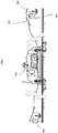
- FIG. 3 a side view of a part of the self-propelled carriage for a system according to the invention with a schematic representation of the current flows
- Figure 4 a side view of a system according to the invention with a schematic representation of the current flows
- Figure 5 Flow chart of the system according to the invention in one embodiment.
- Intermediate stations are of course also possible, in which data receiving and/or transmitting devices can be arranged between the user/operator and the trolley.
- a self-propelled carriage 101 runs on at least one support cable 102 by means of support rollers 106.
- the rollers 106 and/or the connection between the rollers and the carriage 101 are electrically insulated.
- a signal receiving and transmitting device 105 on the self-propelled carriage and at least one signal receiving and transmitting device 203 is interposed in a downstream or upstream station.
- the self-propelled carriage 101 has at least one actuator that moves the carriage along the support cable 102 in the illustrated embodiment with the aid of drive rollers 107 that interact with a tow cable 103 and move the self-propelled carriage 101 .
- the drive is preferably an electric motor, which can also function as a power generator and generates power when the car is driving downhill, for example.
- the electric motor or another electric motor drives the lifting system arranged on the carriage 101 and also in this case, when the load is lowered by the lifting system, electrical current can be generated which can be used directly by the system or supplies a battery arranged on the carriage.
- the actuator is controlled by a signal receiving device 105, which is connected via the signal receiving device 105 on the self-propelled car and at least one signal receiving device 203 at a downhill or uphill station to a wireless receiving and/or transmitting device 204 and receives commands from a user/operator 201 , which, via the signal receiving device 105, detects the movement of the self-propelled car 101 and a rope for lifting/unloading a load 104, e.g. As wood / trees can control.
- a signal receiving device 105 which is connected via the signal receiving device 105 on the self-propelled car and at least one signal receiving device 203 at a downhill or uphill station to a wireless receiving and/or transmitting device 204 and receives commands from a user/operator 201 , which, via the signal receiving device 105, detects the movement of the self-propelled car 101 and a rope for lifting/unloading a load 104, e.g. As wood / trees can control.
- the attached flowchart shows an operation of the system according to the invention, in which the system is switched on in step 1 and detects in step 2 whether an operator is connected to the signal receiving and transmitting device 105 via a wireless device 201 through the receiving and/or transmitting device 204 is.
- the system chooses path A and enters phase 6 active communication, ie it communicates via a cable 102 with at least one station, e.g. B. the downstream and / or upstream station. If no acknowledgment signal is received, the signal receiving device 105 selects path A and goes to phase 8, performs a regular stop of the carriage 101 and waits until a new signal is received.
- the system chooses path B and enters wireless communication in phase 3 via the signal receiving transmitter device 105, which is connected to the device 204 that receives the signal from the user /operator with wireless device 201 sends/receives.
- the Wagen101 is in the radio field 202 of the device 201.
- the system receives the stop signal in step 4, e.g. B. by an emergency stop button, it chooses path B and goes to step 5, in which it presses the emergency stop button.
- the cart remains in this state until unlocked by a signal from the wireless operator/user or by a signal transmitted by at least one cable 102 .
- a signal-receiving transmitting device 203 located down the valley and/or up the mountain is supplied with power via the cables 102, 103, so that the device 203 does not require its own power source.
- At least one downhill and/or uphill signal-receiving transmission device 203 is supplied with power by energy stores such as batteries or capacitors.
- the signal from the carriage towards the downhill and/or uphill station and the signal from the downhill and/or uphill station towards the carriage are sent via the cables 102, 103 by means of a current change on the cables 102, 103.
- the signal from the carriage to the downstream and/or uphill station and the signal from the downstream and/or upstream station to the carriage are transmitted via the cables by means of frequency change of the signal on the cables.
- the signal from the carriage to the downhill and/or uphill station and the signal from the downhill and/or uphill station to the carriage are transmitted via the cables by changing the tension level on the cables.
- the signal from the carriage to the downhill and/or uphill station and the signal from the downhill and/or uphill station to the carriage via the cables is digitally transmitted on the cables.
Landscapes
- Engineering & Computer Science (AREA)
- Mechanical Engineering (AREA)
- Automation & Control Theory (AREA)
- Ropes Or Cables (AREA)
- Selective Calling Equipment (AREA)
Applications Claiming Priority (1)
| Application Number | Priority Date | Filing Date | Title |
|---|---|---|---|
| IT102020000029756A IT202000029756A1 (it) | 2020-12-03 | 2020-12-03 | Impianto a fune con sistema di comando a distanza in particolare per il trasporto di materiale come per esempio legno |
Publications (1)
| Publication Number | Publication Date |
|---|---|
| EP4008676A1 true EP4008676A1 (fr) | 2022-06-08 |
Family
ID=74669359
Family Applications (1)
| Application Number | Title | Priority Date | Filing Date |
|---|---|---|---|
| EP21203111.6A Withdrawn EP4008676A1 (fr) | 2020-12-03 | 2021-10-18 | Système d'installation à câbles à télécommande, en particulier pour le transport de matériaux tels que le bois |
Country Status (2)
| Country | Link |
|---|---|
| EP (1) | EP4008676A1 (fr) |
| IT (1) | IT202000029756A1 (fr) |
Cited By (2)
| Publication number | Priority date | Publication date | Assignee | Title |
|---|---|---|---|---|
| CN115246556A (zh) * | 2022-07-22 | 2022-10-28 | 浙江森林生物科技有限公司 | 一种山区竹子采伐用运输系统及其方法 |
| AT526052A4 (de) * | 2022-07-15 | 2023-11-15 | Mm Forsttechnik Gmbh | Vorrichtung zur Stützung eines Zugseils einer Seilkrananlage |
Citations (6)
| Publication number | Priority date | Publication date | Assignee | Title |
|---|---|---|---|---|
| DE3528655A1 (de) | 1984-08-21 | 1986-03-06 | VEB Forsttechnik Oberlichtenau Betrieb des VEB Kombinat Forsttechnik Waren, DDR 9108 Auerswalde | Schaltvorrichtung fuer seilbahnwagen zur lastbefoerderung |
| JPS6221695A (ja) * | 1985-07-17 | 1987-01-30 | 平野 耕三 | 多軸複胴無線制御空中自動搬器 |
| EP0250392A1 (fr) | 1986-05-20 | 1987-12-23 | Robert Fallmann | Grue à câble |
| DE4020843C1 (en) * | 1990-06-29 | 1991-05-16 | Dietrich Gerhard 7800 Freiburg De Ellsaesser | Crane for handling felled trees - has haulage cable moving carriage along fixed support cable |
| JP2003096679A (ja) * | 2001-09-26 | 2003-04-03 | Ishikawajima Harima Heavy Ind Co Ltd | ワイヤーロープ及びそれを用いたケーブルクレーン |
| DE202010008078U1 (de) | 2010-07-14 | 2010-10-07 | Wilbert Turmkrane Gmbh | Sicherheitssystem für eine Laufkatze eines Krans |
-
2020
- 2020-12-03 IT IT102020000029756A patent/IT202000029756A1/it unknown
-
2021
- 2021-10-18 EP EP21203111.6A patent/EP4008676A1/fr not_active Withdrawn
Patent Citations (6)
| Publication number | Priority date | Publication date | Assignee | Title |
|---|---|---|---|---|
| DE3528655A1 (de) | 1984-08-21 | 1986-03-06 | VEB Forsttechnik Oberlichtenau Betrieb des VEB Kombinat Forsttechnik Waren, DDR 9108 Auerswalde | Schaltvorrichtung fuer seilbahnwagen zur lastbefoerderung |
| JPS6221695A (ja) * | 1985-07-17 | 1987-01-30 | 平野 耕三 | 多軸複胴無線制御空中自動搬器 |
| EP0250392A1 (fr) | 1986-05-20 | 1987-12-23 | Robert Fallmann | Grue à câble |
| DE4020843C1 (en) * | 1990-06-29 | 1991-05-16 | Dietrich Gerhard 7800 Freiburg De Ellsaesser | Crane for handling felled trees - has haulage cable moving carriage along fixed support cable |
| JP2003096679A (ja) * | 2001-09-26 | 2003-04-03 | Ishikawajima Harima Heavy Ind Co Ltd | ワイヤーロープ及びそれを用いたケーブルクレーン |
| DE202010008078U1 (de) | 2010-07-14 | 2010-10-07 | Wilbert Turmkrane Gmbh | Sicherheitssystem für eine Laufkatze eines Krans |
Cited By (4)
| Publication number | Priority date | Publication date | Assignee | Title |
|---|---|---|---|---|
| AT526052A4 (de) * | 2022-07-15 | 2023-11-15 | Mm Forsttechnik Gmbh | Vorrichtung zur Stützung eines Zugseils einer Seilkrananlage |
| AT526052B1 (de) * | 2022-07-15 | 2023-11-15 | Mm Forsttechnik Gmbh | Vorrichtung zur Stützung eines Zugseils einer Seilkrananlage |
| CN115246556A (zh) * | 2022-07-22 | 2022-10-28 | 浙江森林生物科技有限公司 | 一种山区竹子采伐用运输系统及其方法 |
| CN115246556B (zh) * | 2022-07-22 | 2023-09-19 | 浙江强村富民竹产业有限公司 | 一种山区竹子采伐用运输系统及其方法 |
Also Published As
| Publication number | Publication date |
|---|---|
| IT202000029756A1 (it) | 2022-06-03 |
Similar Documents
| Publication | Publication Date | Title |
|---|---|---|
| EP4008676A1 (fr) | Système d'installation à câbles à télécommande, en particulier pour le transport de matériaux tels que le bois | |
| EP2272787A1 (fr) | Bras de poussée téléscopique utilisé en particulier pour un dispositif de réception de charges | |
| EP1837264A2 (fr) | Procédé d'exploitation d'une installation de téléphérique avec une sécurité améliorée, et installation de téléphérique correspondante | |
| WO2014166582A1 (fr) | Grue comprenant une flèche, l'alimentation électrique du crochet de charge et/ou du chariot roulant s'effectuant par l'intermédiaire d'un câble transmettant des forces de traction | |
| WO2019243302A1 (fr) | Chariot universel comprenant un déroulement par contrainte du câble de traction ou du câble de levage dans un fonctionnement à 2 et à 3 câbles | |
| WO2015196221A1 (fr) | Installation de téléphérique | |
| AT504615A2 (de) | Vorrichtung zum speichern von fahrbetriebsmitteln einer seilbahnanlage in einem speicherbereich | |
| DE102016222024A1 (de) | Anhängergespann, Anhänger, Kontrolleinheit, Computerprogrammprodukt und Verfahren zum Steuern eines Anhängers in einem Anhängergespann | |
| DE102020120413A1 (de) | Radsatztransporteinheit für das Bewegen eines Radsatzes auf einem Gleis, Anordnung und Verfahren | |
| EP2401169A2 (fr) | Collecteur de courant et système de transmission d'énergie | |
| EP0157192A2 (fr) | Méthode et dispositif pour relier une prise de courant d'un véhicule à trolley à un système à rails conducteurs | |
| EP3297946B1 (fr) | Treuil de puits mobile | |
| AT516963B1 (de) | Anlage zur Versorgung mindestens eines elektrischen Verbrauchers bzw. eines Energiespeichers mit Gleichstrom | |
| WO2011095285A1 (fr) | Installation de transport pour le transport d'objets | |
| CH694046A5 (de) | Rangieranlage. | |
| DE10205931C1 (de) | Anordnung zum Übertragen von Energie und Steuersignalen an Förderanlagen | |
| DE102008047755A1 (de) | Vorrichtung und Verfahren zur Steuerung von Elektrohängebahnen | |
| DE10143287B4 (de) | Verfahren und Anordnung zum Positionieren von Förderwagen | |
| DE102012024857A1 (de) | Verfahren und Vorrichtungen zur Beschleunigung und Bewegung von Zügen | |
| EP4245923B1 (fr) | Engin électrique de génie civil et procédé associé de son utilisation | |
| EP2687476B1 (fr) | Procédé et dispositif de surveillance de conteneurs de refroidissement dans des terminaux et analogues | |
| DE102022209269A1 (de) | Datenübertragungsvorrichtung für eine hebebühne | |
| EP1065126B1 (fr) | Installation de convoyage pour transporter, déplacer, distribuer et positionner des wagons ferroviaires | |
| DE2327004A1 (de) | Transporteinrichtung fuer schienengebundene transportwagen | |
| DE102017002955B4 (de) | Verfahren zum Betrieb einer Seilbahn und Seilbahn als solche |
Legal Events
| Date | Code | Title | Description |
|---|---|---|---|
| PUAI | Public reference made under article 153(3) epc to a published international application that has entered the european phase |
Free format text: ORIGINAL CODE: 0009012 |
|
| STAA | Information on the status of an ep patent application or granted ep patent |
Free format text: STATUS: THE APPLICATION HAS BEEN PUBLISHED |
|
| AK | Designated contracting states |
Kind code of ref document: A1 Designated state(s): AL AT BE BG CH CY CZ DE DK EE ES FI FR GB GR HR HU IE IS IT LI LT LU LV MC MK MT NL NO PL PT RO RS SE SI SK SM TR |
|
| STAA | Information on the status of an ep patent application or granted ep patent |
Free format text: STATUS: REQUEST FOR EXAMINATION WAS MADE |
|
| 17P | Request for examination filed |
Effective date: 20221026 |
|
| RBV | Designated contracting states (corrected) |
Designated state(s): AL AT BE BG CH CY CZ DE DK EE ES FI FR GB GR HR HU IE IS IT LI LT LU LV MC MK MT NL NO PL PT RO RS SE SI SK SM TR |
|
| RAP3 | Party data changed (applicant data changed or rights of an application transferred) |
Owner name: LEITALPIN GMBH-SRL |
|
| RIC1 | Information provided on ipc code assigned before grant |
Ipc: B66C 21/00 20060101ALI20230206BHEP Ipc: B66C 13/40 20060101AFI20230206BHEP |
|
| GRAP | Despatch of communication of intention to grant a patent |
Free format text: ORIGINAL CODE: EPIDOSNIGR1 |
|
| STAA | Information on the status of an ep patent application or granted ep patent |
Free format text: STATUS: GRANT OF PATENT IS INTENDED |
|
| INTG | Intention to grant announced |
Effective date: 20230320 |
|
| STAA | Information on the status of an ep patent application or granted ep patent |
Free format text: STATUS: THE APPLICATION IS DEEMED TO BE WITHDRAWN |
|
| 18D | Application deemed to be withdrawn |
Effective date: 20230801 |