EP4008676A1 - Cableway system with remote control, in particular for transporting material such as wood - Google Patents
Cableway system with remote control, in particular for transporting material such as wood Download PDFInfo
- Publication number
- EP4008676A1 EP4008676A1 EP21203111.6A EP21203111A EP4008676A1 EP 4008676 A1 EP4008676 A1 EP 4008676A1 EP 21203111 A EP21203111 A EP 21203111A EP 4008676 A1 EP4008676 A1 EP 4008676A1
- Authority
- EP
- European Patent Office
- Prior art keywords
- station
- signal
- carriage
- cables
- downhill
- Prior art date
- Legal status (The legal status is an assumption and is not a legal conclusion. Google has not performed a legal analysis and makes no representation as to the accuracy of the status listed.)
- Withdrawn
Links
- 239000000463 material Substances 0.000 title description 4
- 239000002023 wood Substances 0.000 title description 4
- 230000005540 biological transmission Effects 0.000 claims description 4
- 239000003990 capacitor Substances 0.000 claims description 2
- 238000004146 energy storage Methods 0.000 claims 1
- 238000011144 upstream manufacturing Methods 0.000 description 7
- 230000008054 signal transmission Effects 0.000 description 3
- 239000000725 suspension Substances 0.000 description 3
- 238000007792 addition Methods 0.000 description 1
- 238000006073 displacement reaction Methods 0.000 description 1
- 238000012986 modification Methods 0.000 description 1
- 230000004048 modification Effects 0.000 description 1
- 238000012806 monitoring device Methods 0.000 description 1
Images


Classifications
-
- B—PERFORMING OPERATIONS; TRANSPORTING
- B66—HOISTING; LIFTING; HAULING
- B66C—CRANES; LOAD-ENGAGING ELEMENTS OR DEVICES FOR CRANES, CAPSTANS, WINCHES, OR TACKLES
- B66C13/00—Other constructional features or details
- B66C13/18—Control systems or devices
- B66C13/40—Applications of devices for transmitting control pulses; Applications of remote control devices
-
- B—PERFORMING OPERATIONS; TRANSPORTING
- B66—HOISTING; LIFTING; HAULING
- B66C—CRANES; LOAD-ENGAGING ELEMENTS OR DEVICES FOR CRANES, CAPSTANS, WINCHES, OR TACKLES
- B66C21/00—Cable cranes, i.e. comprising hoisting devices running on aerial cable-ways
Definitions
- the present invention relates to a cable car with a remote control system, in particular for the transport of material such as wood, according to the preamble of patent claim 1.
- carriages which are tied to the cable and move by the displacement of the carrying cable to which they are fixed.
- a second type of carriage has a drive that moves the carriage directly on the suspension cable.
- the carriages run along the carrying cable and are moved by a traction cable via a stationary winch.
- the present invention relates to cable car systems with carriages that move on cables, in particular are carried by a supporting cable and move by means of a so-called traction cable, which is preferably arranged below the supporting cable.
- This carriage preferably has a winch for lifting and/or offloading material, e.g. As trees and the like.
- the system is often remotely controlled using a device that sends remote signals, e.g. B. a radio remote control or the like.
- a device that sends remote signals e.g. B. a radio remote control or the like.
- the user controlling the self-propelled car may lose contact with the car, and in this case the self-propelled car is no longer under the user's direct control, which entails the risks of such loss of control.
- DE 352 8655 contains a self-propelled cart that can be controlled via a radio remote control, and this control activates a hydraulic system on the self-propelled cart. No additional safety systems to control the self-propelled car are released.
- the DE 20 2010 008 078 Contains a safety system for crane trolleys, which is operated by means of a remote control and has a safety system with a rope to brake the trolley. This type of safety system is suitable for cranes where the travel of the trolley is limited.
- substantially means a deviation of angle plus or minus 5° and length plus or minus 5% of the length of the specified object.
- the object of the present invention is to implement a control system for a cableway with at least one suspension cable and at least one traction cable with a self-propelled carriage that has an actuator for movement along the cable.
- a cable car system is proposed with a remote control system with at least one support cable and at least one traction cable, which are arranged between a downhill station and an uphill station, and with a self-propelled carriage that has a support frame that can be moved by means of at least one support roller on a support cable , on which at least one actuator is arranged.
- At least one data communication device for sending and receiving signals from a control unit is arranged on the self-propelled carriage from a control device, and a signal transmission/reception device is interposed between at least two cables, which sends and receives signals by means of the cables on the self-propelled carriage, and is at least one Signal transmitting/receiving device is arranged between the same two cables at a station, preferably at a station located down the valley and/or up the mountain, and the two devices and the cables form a communication circuit, it also being possible for there to be more than one communication circuit.
- At least one communication circuit is implemented by the at least two communication devices arranged between the two cables, but there can also be several circuits, e.g. with the downstream and upstream station.
- This cable communication is preferably used as an auxiliary system, i. H. it is only used when there is no signal from the operator/user, ie. H. when the carriage or carriage is outside the transmission range of the operator/user.
- the self-propelled trolley can preferably be equipped with an electrically operated handling and/or lifting system.
- the actuator can also be a power generator, e.g. when a load is lowered by the winch, electrical energy is generated and this electrical energy can be fed into a battery that powers the communication system via the cables and/or powers the communication system directly via the cables.
- suspension cables may be present, one of which z. B. is electrically isolated.
- Devices which feed and/or receive the signal into the cable(s) can also be arranged at the ends of the cables and/or at the signal feeding stations.
- the electric current is fed in at variable intervals.
- the variable power supply feeds the signal which is then picked up by the units in the station and/or on the wagon and from which the commands/information to control the wagon are derived.
- This communication system makes it possible to send a few bytes per second, which is enough to remotely control the self-propelled trolley and all the devices installed on the trolley, such as winches and gripping devices, monitoring devices, etc.
- Devices for receiving/transmitting signals are preferably arranged in the downstream and/or upstream base station in such a way that there are also means for wireless signal transmission. Since there is normally always an operator present in the perimeter of the downstream or upstream station, the system described above enables communication with the operator. The system described enables communication with the car even if it is out of range of the remote control device, since the Communication takes place via the ropes, with which there is always contact.
- the regular communication only takes place via the long-distance communication device when it is no longer in contact with the vehicle.
- the system on the carriage and/or the system in a station activates the communication system via the cables.
- the system can be arranged to send signals down the cables at certain intervals or after the system has been installed to check that the system is working.
- FIG. 3 a side view of a part of the self-propelled carriage for a system according to the invention with a schematic representation of the current flows
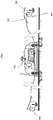
- Figure 4 a side view of a system according to the invention with a schematic representation of the current flows
- Figure 5 Flow chart of the system according to the invention in one embodiment.
- Intermediate stations are of course also possible, in which data receiving and/or transmitting devices can be arranged between the user/operator and the trolley.
- a self-propelled carriage 101 runs on at least one support cable 102 by means of support rollers 106.
- the rollers 106 and/or the connection between the rollers and the carriage 101 are electrically insulated.
- a signal receiving and transmitting device 105 on the self-propelled carriage and at least one signal receiving and transmitting device 203 is interposed in a downstream or upstream station.
- the self-propelled carriage 101 has at least one actuator that moves the carriage along the support cable 102 in the illustrated embodiment with the aid of drive rollers 107 that interact with a tow cable 103 and move the self-propelled carriage 101 .
- the drive is preferably an electric motor, which can also function as a power generator and generates power when the car is driving downhill, for example.
- the electric motor or another electric motor drives the lifting system arranged on the carriage 101 and also in this case, when the load is lowered by the lifting system, electrical current can be generated which can be used directly by the system or supplies a battery arranged on the carriage.
- the actuator is controlled by a signal receiving device 105, which is connected via the signal receiving device 105 on the self-propelled car and at least one signal receiving device 203 at a downhill or uphill station to a wireless receiving and/or transmitting device 204 and receives commands from a user/operator 201 , which, via the signal receiving device 105, detects the movement of the self-propelled car 101 and a rope for lifting/unloading a load 104, e.g. As wood / trees can control.
- a signal receiving device 105 which is connected via the signal receiving device 105 on the self-propelled car and at least one signal receiving device 203 at a downhill or uphill station to a wireless receiving and/or transmitting device 204 and receives commands from a user/operator 201 , which, via the signal receiving device 105, detects the movement of the self-propelled car 101 and a rope for lifting/unloading a load 104, e.g. As wood / trees can control.
- the attached flowchart shows an operation of the system according to the invention, in which the system is switched on in step 1 and detects in step 2 whether an operator is connected to the signal receiving and transmitting device 105 via a wireless device 201 through the receiving and/or transmitting device 204 is.
- the system chooses path A and enters phase 6 active communication, ie it communicates via a cable 102 with at least one station, e.g. B. the downstream and / or upstream station. If no acknowledgment signal is received, the signal receiving device 105 selects path A and goes to phase 8, performs a regular stop of the carriage 101 and waits until a new signal is received.
- the system chooses path B and enters wireless communication in phase 3 via the signal receiving transmitter device 105, which is connected to the device 204 that receives the signal from the user /operator with wireless device 201 sends/receives.
- the Wagen101 is in the radio field 202 of the device 201.
- the system receives the stop signal in step 4, e.g. B. by an emergency stop button, it chooses path B and goes to step 5, in which it presses the emergency stop button.
- the cart remains in this state until unlocked by a signal from the wireless operator/user or by a signal transmitted by at least one cable 102 .
- a signal-receiving transmitting device 203 located down the valley and/or up the mountain is supplied with power via the cables 102, 103, so that the device 203 does not require its own power source.
- At least one downhill and/or uphill signal-receiving transmission device 203 is supplied with power by energy stores such as batteries or capacitors.
- the signal from the carriage towards the downhill and/or uphill station and the signal from the downhill and/or uphill station towards the carriage are sent via the cables 102, 103 by means of a current change on the cables 102, 103.
- the signal from the carriage to the downstream and/or uphill station and the signal from the downstream and/or upstream station to the carriage are transmitted via the cables by means of frequency change of the signal on the cables.
- the signal from the carriage to the downhill and/or uphill station and the signal from the downhill and/or uphill station to the carriage are transmitted via the cables by changing the tension level on the cables.
- the signal from the carriage to the downhill and/or uphill station and the signal from the downhill and/or uphill station to the carriage via the cables is digitally transmitted on the cables.
Abstract
Die Erfindung betrifft eine Seilbahnanlage (100) mit einer Talstation und einer Bergstation, wobei zwischen der Talstation und der Bergstation ein Tragseil (102) gespannt und zwischen der Talstation und der Bergstation ein Zugseil (103) verlegt ist und auf mindestens einem Tragseil (102) ein selbstfahrender Laufwagen (101) mittels Tragrollen (106) läuft und auf dem Laufwagen (101) mindestens eine drahtlose Signalempfangs-Sendeeinrichtung (204) zum Empfang von Signalen eines Benutzers/Bedieners (201) angeordnet ist.Erfindungsgemäß ist eine signalempfangende Sendevorrichtung (105) zwischen mindestens zwei Seilen (102, 103) auf dem Wagen (101) angeordnet und dass mindestens eine signalempfangende Sendevorrichtung (203) zwischen den beiden Seilen in einer Station angeordnet ist, die mindestens einen Kreislauf zwischen den Seilen (102, 103) und den Vorrichtungen (105, 203) bildet.The invention relates to a cable car system (100) with a valley station and a mountain station, with a carrying cable (102) stretched between the valley station and the mountain station and a traction cable (103) being laid between the valley station and the mountain station and on at least one carrying cable (102) a self-propelled carriage (101) runs by means of support rollers (106) and at least one wireless signal receiving and transmitting device (204) for receiving signals from a user/operator (201) is arranged on the carriage (101). According to the invention, a signal receiving transmitting device (105) between at least two ropes (102, 103) on the carriage (101) and that at least one signal-receiving transmitting device (203) is arranged between the two ropes in a station that forms at least one circuit between the ropes (102, 103) and the devices (105, 203).
Description
Die vorliegende Erfindung betrifft eine Seilbahn mit einem Fernsteuerungssystem, insbesondere für den Transport von Material wie beispielsweise Holz gemäß dem Oberbegriff des Patentanspruchs 1.The present invention relates to a cable car with a remote control system, in particular for the transport of material such as wood, according to the preamble of
Es sind verschiedene Arten von Seilbahnen mit Laufwagen mit unterschiedlichen Arten der Seilführung bekannt. Im Allgemeinen sind Laufwagen bekannt, die an das Seil gebunden sind und sich durch die Verschiebung des Tragseils bewegen, mit dem sie fest verbunden sind.Various types of cable cars with carriages with different types of cable routing are known. In general, carriages are known which are tied to the cable and move by the displacement of the carrying cable to which they are fixed.
Eine zweite Art von Laufwagen verfügt über einen Antrieb, der die Laufwagen direkt auf dem Tragseil bewegt.A second type of carriage has a drive that moves the carriage directly on the suspension cable.
Bei einer dritten Variante laufen die Laufwagen am Tragseil entlang und werden durch ein Zugseil über eine stationäre Winde bewegt.In a third variant, the carriages run along the carrying cable and are moved by a traction cable via a stationary winch.
Die vorliegende Erfindung betrifft Seilbahnanlagen mit Laufwagen, die sich auf Seilen bewegen, insbesondere von einem Tragseil getragen werden und sich mittels eines sogenannten Zugseils bewegen, das vorzugsweise unterhalb des Tragseils angeordnet ist. Das bedeutet, dass die Laufwagen z. B. mittels Rollen auf dem Tragseil bewegt werden und die Bewegung mittels eines an den Laufwagen angeordneten Antriebssystems für ein Zugseil, das ein nicht bewegliches Seil ist, erfolgt und den Laufwagen zieht. Dieser Laufwagen verfügt vorzugsweise über eine Winde zum Anheben und/oder Abladen von Material, z. B. Bäumen und dergleichen.The present invention relates to cable car systems with carriages that move on cables, in particular are carried by a supporting cable and move by means of a so-called traction cable, which is preferably arranged below the supporting cable. This means that the carriage z. B. be moved by means of rollers on the support cable and the movement by means of a arranged on the carriage drive system for a traction cable, which is a non-movable cable, and pulls the carriage. This carriage preferably has a winch for lifting and/or offloading material, e.g. As trees and the like.
Das System wird häufig mit Hilfe eines Geräts ferngesteuert, dass Fernsignale sendet, z. B. einer Funkfernsteuerung oder ähnlichem. Während der Benutzung kann der Benutzer, der den selbstfahrenden Wagen steuert, den Kontakt mit dem Wagen verlieren, und in diesem Fall befindet sich der selbstfahrende Wagen nicht mehr unter der direkten Kontrolle des Benutzers, was mit den Risiken eines solchen Kontrollverlusts verbunden ist.The system is often remotely controlled using a device that sends remote signals, e.g. B. a radio remote control or the like. During use, the user controlling the self-propelled car may lose contact with the car, and in this case the self-propelled car is no longer under the user's direct control, which entails the risks of such loss of control.
Die
In der
Keines der bisher beschriebenen Systeme veröffentlicht ein zweites und/oder alternatives System, mit dem die Steuerung des selbstfahrenden Wagens übernommen werden kann, um eine größere Signalfernübertragung zu gewährleisten.None of the systems described so far disclose a second and/or alternative system for controlling the self-propelled Wagens can be taken over to ensure greater long-distance signal transmission.
In der vorliegenden Beschreibung und den beigefügten Ansprüchen bedeutet "im Wesentlichen" eine Abweichung des Winkels plus oder minus 5° und der Länge plus oder minus 5% der Länge des angegebenen Objekts.As used in the present specification and appended claims, "substantially" means a deviation of angle plus or
Aufgabe der vorliegenden Erfindung ist es, ein Steuerungssystem für eine Seilbahn mit mindestens einem Tragseil und mindestens einem Zugseil mit einem selbstfahrenden Laufwagen zu realisieren, die einen Aktuator zur Bewegung entlang des Seils aufweist.The object of the present invention is to implement a control system for a cableway with at least one suspension cable and at least one traction cable with a self-propelled carriage that has an actuator for movement along the cable.
Diese Aufgabe wird durch eine Seilbahnanlage mit einem Fernsteuerungssystem, insbesondere für den Transport von Material wie Holz, nach Anspruch 1 gelöst.This object is achieved by a cable car system with a remote control system, in particular for the transport of material such as wood, according to
Erfindungsgemäß wird eine Seilbahnanlage mit einem Fernsteuerungssystem mit mindestens einem Tragseil und mindestens einem Zugseil, die zwischen einer talwärts und einer bergwärts gelegenen Station angeordnet sind, und mit einem selbstfahrenden Laufwagen vorgeschlagen, der einen Tragrahmen aufweist, der mittels mindestens einer Tragrolle an einem Tragseil beweglich ist, an dem mindestens ein Stellantrieb angeordnet ist.According to the invention, a cable car system is proposed with a remote control system with at least one support cable and at least one traction cable, which are arranged between a downhill station and an uphill station, and with a self-propelled carriage that has a support frame that can be moved by means of at least one support roller on a support cable , on which at least one actuator is arranged.
Erfindungsgemäß ist auf dem selbstfahrenden Laufwagen mindestens eine Datenkommunikationseinrichtung zum Senden und Empfangen von Signalen einer Steuereinheit von einer Steuereinrichtung angeordnet, und ist zwischen mindestens zwei Seilen eine Signalsende-/Empfangseinrichtung zwischengeschaltet , die mittels der Seile auf dem selbstfahrenden Laufwagen Signale sendet und empfängt, und ist mindestens eine Signalsende-/Empfangseinrichtung zwischen denselben zwei Seilen an einer Station, vorzugsweise an einer talabwärts und/oder bergwärts gelegenen Station, angeordnet, und bilden die beiden Einrichtungen und die Seile einen Kommunikationskreis, wobei auch mehr als ein Kommunikationskreis vorhanden sein kann.According to the invention, at least one data communication device for sending and receiving signals from a control unit is arranged on the self-propelled carriage from a control device, and a signal transmission/reception device is interposed between at least two cables, which sends and receives signals by means of the cables on the self-propelled carriage, and is at least one Signal transmitting/receiving device is arranged between the same two cables at a station, preferably at a station located down the valley and/or up the mountain, and the two devices and the cables form a communication circuit, it also being possible for there to be more than one communication circuit.
Diese Kommunikation kann realisiert werden, da es keinen Kurzschluss zwischen den Seilen gibt. Durch die mindestens zwei zwischen den beiden Seilen angeordneten Kommunikationseinrichtungen wird mindestens ein Kommunikationskreislauf realisiert, es können jedoch auch mehrere Kreisläufe z.B. mit der nach- und vorgelagerten Station vorhanden sein.This communication can be realized because there is no short circuit between the ropes. At least one communication circuit is implemented by the at least two communication devices arranged between the two cables, but there can also be several circuits, e.g. with the downstream and upstream station.
Diese Seilkommunikation wird vorzugsweise als Hilfssystem eingesetzt, d. h. sie kommt nur dann zum Einsatz, wenn kein Signal vom Bediener/Benutzer vorliegt, d. h. wenn sich der Laufwagen bzw. Schlitten außerhalb des Sendebereichs des Bedieners/Benutzers befindet.This cable communication is preferably used as an auxiliary system, i. H. it is only used when there is no signal from the operator/user, ie. H. when the carriage or carriage is outside the transmission range of the operator/user.
Der selbstfahrende Wagen kann vorzugsweise mit einem elektrisch betriebenen Handhabungs- und/oder Hebesystem ausgestattet sein. Der Aktuator kann auch ein Stromgenerator sein, z. B. wenn eine Last durch die Winde abgesenkt wird, wird elektrische Energie erzeugt, und diese elektrische Energie kann in eine Batterie eingespeist werden, die das Kommunikationssystem über die Seile mit Strom versorgt und/oder das Kommunikationssystem direkt über die Seile mit Strom versorgt.The self-propelled trolley can preferably be equipped with an electrically operated handling and/or lifting system. The actuator can also be a power generator, e.g. when a load is lowered by the winch, electrical energy is generated and this electrical energy can be fed into a battery that powers the communication system via the cables and/or powers the communication system directly via the cables.
Um ein Seil vom anderen zu isolieren, kann es natürlich auch genügen, wenn nur ein Seil von dem Laufwagen isoliert wird, während das andere Seil in Kontakt mit dem Laufwagen bleibt.In order to insulate one rope from the other, it can of course also be sufficient if only one rope from the carriage is isolated while the other rope remains in contact with the carriage.
In einer weiteren Ausführungsform können mehrere Tragseile vorhanden sein, von denen eines z. B. elektrisch isoliert ist.In a further embodiment, several suspension cables may be present, one of which z. B. is electrically isolated.
An den Enden der Seile und/oder an den Signaleinspeisestationen können auch Geräte angeordnet sein, die das Signal in das/die Seil(e) einspeisen und/oder empfangen. Der elektrische Strom wird in variablen Abständen eingespeist. Über die variable Stromversorgung wird das Signal eingespeist, das dann von den Einheiten in der Station und/oder auf dem Wagen erfasst wird und aus dem die Befehle/Informationen zur Steuerung des Wagens abgeleitet werden.Devices which feed and/or receive the signal into the cable(s) can also be arranged at the ends of the cables and/or at the signal feeding stations. The electric current is fed in at variable intervals. The variable power supply feeds the signal which is then picked up by the units in the station and/or on the wagon and from which the commands/information to control the wagon are derived.
Dieses Kommunikationssystem ermöglicht es, einige Bytes pro Sekunde zu senden, die ausreichen, um den selbstfahrenden Wagen und alle auf dem Wagen angebrachten Vorrichtungen wie Winde und Greifvorrichtungen, Überwachungsvorrichtungen usw. fernzusteuern.This communication system makes it possible to send a few bytes per second, which is enough to remotely control the self-propelled trolley and all the devices installed on the trolley, such as winches and gripping devices, monitoring devices, etc.
In der nachgelagerten und/oder vorgelagerten Basisstation sind vorzugsweise Einrichtungen zum Empfangen/Senden von Signalen so angeordnet, dass auch Mittel zur drahtlosen Signalübertragung vorhanden sind. Da normalerweise immer ein Bediener im Umkreis der nach- oder vorgelagerten Station anwesend ist, ermöglicht das oben beschriebene System die Kommunikation mit dem Bediener. Das beschriebene System ermöglicht die Kommunikation mit dem Wagen auch dann, wenn er sich außerhalb der Reichweite der Fernsteuerungseinrichtung befindet, da die Kommunikation über die Seile erfolgt, mit denen immer ein Kontakt besteht.Devices for receiving/transmitting signals are preferably arranged in the downstream and/or upstream base station in such a way that there are also means for wireless signal transmission. Since there is normally always an operator present in the perimeter of the downstream or upstream station, the system described above enables communication with the operator. The system described enables communication with the car even if it is out of range of the remote control device, since the Communication takes place via the ropes, with which there is always contact.
Die reguläre Kommunikation erfolgt in einer bevorzugten Ausführungsform über die Fernkommunikationseinrichtung erst dann, wenn diese nicht mehr in Kontakt mit dem Fahrzeug steht. Das System auf dem Wagen und/oder das System in einer Station aktiviert das Kommunikationssystem über die Seile.In a preferred embodiment, the regular communication only takes place via the long-distance communication device when it is no longer in contact with the vehicle. The system on the carriage and/or the system in a station activates the communication system via the cables.
Es kann vorgesehen werden, dass das System in bestimmten Abständen oder nach der Installation des Systems Signale über die Seile sendet, um zu überprüfen, ob das System funktioniert.The system can be arranged to send signals down the cables at certain intervals or after the system has been installed to check that the system is working.
Weitere Merkmale und Einzelheiten ergeben sich aus den weiteren Ansprüchen und aus der Beschreibung von zwei Ausführungsbeispielen einer Abzieh- /Hebevorrichtung unter Bezugnahme auf die Figuren der beigefügten Zeichnung. Es zeigen
-
Figur 1 -
Figur 2
-
figure 1 a view of a cable car according to the invention, -
figure 2 , side view of a part of a self-propelled carriage for a plant according to the invention,
In
Ein selbstfahrender Wagen 101 läuft auf mindestens einem Tragseil 102 mittels Tragrollen 106. In der vorliegenden Ausführungsform sind die Rollen 106 und/oder die Verbindung zwischen den Rollen und dem Laufwagen 101 elektrisch isoliert. Zwischen den beiden Seilen 102 und 103 ist eine Signalempfangseinrichtung 105 an dem selbstfahrenden Laufwagen und mindestens eine Signalempfangseinrichtung 203 an einer nach- oder vorgelagerten Station angeordnet. Erfindungsgemäß ist es lediglich erforderlich, dass zwischen mindestens zwei Seilen 102, 103 eine Signalempfangs-Sendeeinrichtung 105 auf dem selbstfahrenden Wagen und mindestens eine Signalempfangs-Sendeeinrichtung 203 in einer nach- oder vorgelagerten Station zwischengeschaltet ist.A self-propelled
Der selbstfahrende Laufwagen 101 verfügt über mindestens einen Aktuator, der den Laufwagen entlang des Tragseils 102 in der dargestellten Ausführungsform mit Hilfe von Antriebsrollen 107 bewegt, die mit einem Schleppseil 103 zusammenwirken und den selbstfahrende Laufwagen 101 bewegen. Vorzugsweise handelt es sich bei dem Antrieb um einen Elektromotor, der auch als Stromgenerator fungieren kann und Strom erzeugt, wenn der Wagen beispielsweise bergabwärts fährt.The self-propelled
Vorteilhafterweise treibt der Elektromotor oder ein weiterer Elektromotor das am Wagen 101 angeordnete Hebesystem an und auch in diesem Fall kann beim Absenken der Last durch das Hebesystem elektrischer Strom erzeugt werden, der direkt vom System genutzt werden kann oder eine am Wagen angeordnete Batterie versorgt.Advantageously, the electric motor or another electric motor drives the lifting system arranged on the
Der Aktuator wird durch eine Signalempfangseinrichtung 105 gesteuert, die über die Signalempfangseinrichtung 105 am selbstfahrenden Wagen und mindestens eine Signalempfangseinrichtung 203 an einer talwärts oder bergwärts gelegenen Station mit einer drahtlosen Empfangs- und/oder Sendeeinrichtung 204 verbunden ist und Befehle von einem Benutzer/Bediener 201 empfängt, der über die Signalempfangseinrichtung 105 die Bewegung des selbstfahrenden Wagens 101 und eines Seils zum Heben/Abladen einer Last 104, z. B. Holz/Bäume, steuern kann.The actuator is controlled by a
Im beigefügten Flussdiagramm ist ein Betrieb des erfindungsgemäßen Systems dargestellt, bei dem das System in Schritt 1 eingeschaltet wird und in Schritt 2 erkennt, ob ein Bediener über ein drahtloses Gerät 201 durch die Empfangs- und/oder Sendevorrichtung 204 mit der Signalempfangs-Sendevorrichtung 105 verbunden ist.The attached flowchart shows an operation of the system according to the invention, in which the system is switched on in
Wird kein Signal von einem Benutzer/Bediener erkannt, wählt das System den Pfad A und tritt in Phase 6 in die aktive Kommunikation ein, d. h. es kommuniziert über ein Kabel 102 mit mindestens einer Station, z. B. der nach- und/oder vorgelagerten Station. Wird kein Quittierungssignal empfangen, wählt die Signalempfangseinrichtung 105 den Weg A und geht in Phase 8 über, führt einen regulären Halt des Wagens 101 durch und wartet, bis ein neues Signal empfangen wird.If no signal is detected from a user/operator, the system chooses path A and enters
Wenn in Phase 2 ein Signal von einem Benutzer/Bediener erkannt wird, wählt das System den Pfad B und tritt in Phase 3 in die drahtlose Kommunikation über die Signalempfangs-Sendevorrichtung 105 ein, die mit dem Gerät 204 verbunden ist, das das Signal vom Benutzer/Bediener mit dem drahtlosen Gerät 201 sendet/empfängt. Der Wagen101 befindet sich im Funkfeld 202 des Geräts 201. Empfängt das System im Schritt 4 das Stoppsignal, z. B. durch eine Not-Aus-Taste, wählt es den Weg B und geht in Schritt 5 über, in dem es die Not-Aus Taste betätigt. Der Wagen bleibt in diesem Zustand, bis er durch ein Signal des drahtlosen Bedieners/Benutzers oder durch ein Signal, das von mindestens einem Seil 102 übertragen wird, entriegelt wird.If a signal from a user/operator is detected in
Wenn kein Haltesignal empfangen wird, bleibt der Wagen in Schritt 9 betriebsbereit.If no stop signal is received, the carriage remains ready for operation in
Vorteilhafterweise wird eine talwärts und/oder bergwärts gelegene signalempfangende Sendevorrichtung 203 über die Seile 102, 103 mit Strom versorgt, so dass für die Vorrichtung 203 keine eigene Stromquelle erforderlich ist.Advantageously, a signal-receiving
In einer Ausführungsform wird mindestens eine talwärts und/oder bergwärts gelegene signalempfangende Sendevorrichtung 203 durch Energiespeicher wie Batterien oder Kondensatoren mit Strom versorgt.In one embodiment, at least one downhill and/or uphill signal-receiving
Vorteilhafterweise wird das Signal von dem Laufwagen in Richtung der talwärts und/oder bergwärts gelegenen Station und das Signal von der talwärts und/oder bergwärts gelegenen Station in Richtung des Laufwagen über die Seile 102, 103 mittels einer Stromänderung auf den Seilen 102, 103 gesendet.Advantageously, the signal from the carriage towards the downhill and/or uphill station and the signal from the downhill and/or uphill station towards the carriage are sent via the
In einer anderen Ausführungsform wird das Signal von dem Laufwagen zur talwärts und/oder bergwärts gelegenen Station und das Signal von der stromabwärts und/oder stromaufwärts gelegenen Station zum Laufwagen über die Seile mittels Frequenzänderung des Signals auf den Seilen übertragen.In another embodiment, the signal from the carriage to the downstream and/or uphill station and the signal from the downstream and/or upstream station to the carriage are transmitted via the cables by means of frequency change of the signal on the cables.
In einer Bevorzugten Variante wird das das Signal von dem Laufwagen zur talwärts und/oder bergwärts gelegenen Station und das Signal von der talwärts und/oder bergwärts gelegenen Station zum Laufwagen über die Seile mittels Änderung des Spannungsniveaus auf den Seilen übertragen.In a preferred variant, the signal from the carriage to the downhill and/or uphill station and the signal from the downhill and/or uphill station to the carriage are transmitted via the cables by changing the tension level on the cables.
In einer weiteren Variante wird das Signal von dem Laufwagen zur talwärts und/oder bergwärts gelegenen Station und das Signal von der talwärts und/oder bergwärts gelegenen Station zum Laufwagen über die Seile digital auf den Seilen übertragen wird. Schließlich ist es klar, dass Ergänzungen, Änderungen oder Varianten des hier beschriebenen Systems angewandt werden können, ohne den Schutzbereich der beigefügten Ansprüche zu verlassen.In a further variant, the signal from the carriage to the downhill and/or uphill station and the signal from the downhill and/or uphill station to the carriage via the cables is digitally transmitted on the cables. Finally, it is clear that additions, modifications or variants can be applied to the system described here without going beyond the scope of protection of the appended claims.
- 100100
- Seilbahnsystem mit KontrollsystemCable car system with control system
- 101101
- selbstfahrender Wagenself-driving car
- 102102
- Tragseilcarrying rope
- 103103
- Zugseilpull rope
- 104104
- Hubseilhoist rope
- 105105
- Signalempfangsgerätsignal receiving device
- 106106
- Stützrollensupport rollers
- 107107
- Antriebsrollendrive rollers
- 201201
- Benutzer/BetreiberUser/Operator
- 202202
- Funkfeld für drahtlose GeräteRadio field for wireless devices
- 203203
- Vorrichtung zum Senden und Empfangen von StationssignalenDevice for sending and receiving station signals
- 204204
- Wagen für drahtlose SignalempfangsgeräteCart for wireless signal receiving devices
- A =A =
- NEINNO
-
B= JA 1,2,3,4,5,6,7,8,9B=
YES - SystemsteuerungsströmeSystem Control Streams
Claims (9)
Applications Claiming Priority (1)
| Application Number | Priority Date | Filing Date | Title |
|---|---|---|---|
| IT102020000029756A IT202000029756A1 (en) | 2020-12-03 | 2020-12-03 | ROPE SYSTEM WITH REMOTE CONTROL SYSTEM IN PARTICULAR FOR THE TRANSPORT OF MATERIAL SUCH AS WOOD |
Publications (1)
| Publication Number | Publication Date |
|---|---|
| EP4008676A1 true EP4008676A1 (en) | 2022-06-08 |
Family
ID=74669359
Family Applications (1)
| Application Number | Title | Priority Date | Filing Date |
|---|---|---|---|
| EP21203111.6A Withdrawn EP4008676A1 (en) | 2020-12-03 | 2021-10-18 | Cableway system with remote control, in particular for transporting material such as wood |
Country Status (2)
| Country | Link |
|---|---|
| EP (1) | EP4008676A1 (en) |
| IT (1) | IT202000029756A1 (en) |
Cited By (2)
| Publication number | Priority date | Publication date | Assignee | Title |
|---|---|---|---|---|
| CN115246556A (en) * | 2022-07-22 | 2022-10-28 | 浙江森林生物科技有限公司 | Conveying system and method for cutting bamboos in mountainous areas |
| AT526052A4 (en) * | 2022-07-15 | 2023-11-15 | Mm Forsttechnik Gmbh | Device for supporting a pull rope of a cable crane system |
Citations (6)
| Publication number | Priority date | Publication date | Assignee | Title |
|---|---|---|---|---|
| DE3528655A1 (en) | 1984-08-21 | 1986-03-06 | VEB Forsttechnik Oberlichtenau Betrieb des VEB Kombinat Forsttechnik Waren, DDR 9108 Auerswalde | Operating device for aerial-ropeway cars for conveying loads |
| JPS6221695A (en) * | 1985-07-17 | 1987-01-30 | 平野 耕三 | Multispindle double-drum radio control aerial automatic conveyor |
| EP0250392A1 (en) | 1986-05-20 | 1987-12-23 | Robert Fallmann | Cable crane |
| DE4020843C1 (en) * | 1990-06-29 | 1991-05-16 | Dietrich Gerhard 7800 Freiburg De Ellsaesser | Crane for handling felled trees - has haulage cable moving carriage along fixed support cable |
| JP2003096679A (en) * | 2001-09-26 | 2003-04-03 | Ishikawajima Harima Heavy Ind Co Ltd | Wire cord and cable crane using the same |
| DE202010008078U1 (en) | 2010-07-14 | 2010-10-07 | Wilbert Turmkrane Gmbh | Safety system for a trolley of a crane |
-
2020
- 2020-12-03 IT IT102020000029756A patent/IT202000029756A1/en unknown
-
2021
- 2021-10-18 EP EP21203111.6A patent/EP4008676A1/en not_active Withdrawn
Patent Citations (6)
| Publication number | Priority date | Publication date | Assignee | Title |
|---|---|---|---|---|
| DE3528655A1 (en) | 1984-08-21 | 1986-03-06 | VEB Forsttechnik Oberlichtenau Betrieb des VEB Kombinat Forsttechnik Waren, DDR 9108 Auerswalde | Operating device for aerial-ropeway cars for conveying loads |
| JPS6221695A (en) * | 1985-07-17 | 1987-01-30 | 平野 耕三 | Multispindle double-drum radio control aerial automatic conveyor |
| EP0250392A1 (en) | 1986-05-20 | 1987-12-23 | Robert Fallmann | Cable crane |
| DE4020843C1 (en) * | 1990-06-29 | 1991-05-16 | Dietrich Gerhard 7800 Freiburg De Ellsaesser | Crane for handling felled trees - has haulage cable moving carriage along fixed support cable |
| JP2003096679A (en) * | 2001-09-26 | 2003-04-03 | Ishikawajima Harima Heavy Ind Co Ltd | Wire cord and cable crane using the same |
| DE202010008078U1 (en) | 2010-07-14 | 2010-10-07 | Wilbert Turmkrane Gmbh | Safety system for a trolley of a crane |
Cited By (4)
| Publication number | Priority date | Publication date | Assignee | Title |
|---|---|---|---|---|
| AT526052A4 (en) * | 2022-07-15 | 2023-11-15 | Mm Forsttechnik Gmbh | Device for supporting a pull rope of a cable crane system |
| AT526052B1 (en) * | 2022-07-15 | 2023-11-15 | Mm Forsttechnik Gmbh | Device for supporting a pull rope of a cable crane system |
| CN115246556A (en) * | 2022-07-22 | 2022-10-28 | 浙江森林生物科技有限公司 | Conveying system and method for cutting bamboos in mountainous areas |
| CN115246556B (en) * | 2022-07-22 | 2023-09-19 | 浙江强村富民竹产业有限公司 | Transportation system and method for bamboo harvesting in mountain area |
Also Published As
| Publication number | Publication date |
|---|---|
| IT202000029756A1 (en) | 2022-06-03 |
Similar Documents
| Publication | Publication Date | Title |
|---|---|---|
| EP4008676A1 (en) | Cableway system with remote control, in particular for transporting material such as wood | |
| EP2409903B1 (en) | Fully integrated battery and charging devices of a manoeuvring system for trailers | |
| EP1837264A2 (en) | Method for operating a ropeway installation with improved safety, and corresponding ropeway installation | |
| WO2014166582A1 (en) | Crane comprising a crane cantilever arm, wherein the current is supplied to the load hook and/or crane trolley via a rope transmitting tractive forces | |
| WO2019243302A1 (en) | Universal carriage with enforced spooling out of the traction cable and/or of the hoisting cable in 2- and 3-cable operation | |
| WO2015196221A1 (en) | Cable car system | |
| WO2018224344A1 (en) | Drive system for a belt conveyor, method for driving a belt conveyor, belt conveyor, control device, and computer program product | |
| DE102016222024A1 (en) | Trailer trailer, trailer, control unit, computer program product and method of controlling a trailer in a trailer truck | |
| EP2401169A2 (en) | Current collector and energy transmission system | |
| EP0157192A2 (en) | Method and apparatus for connecting a current collector of a trolley vehicle to a power rail system | |
| EP3297946B1 (en) | Mobile shaft winch | |
| AT516963B1 (en) | System for supplying at least one electrical consumer or an energy storage device with direct current | |
| EP2531389A1 (en) | Conveyor system for transporting articles | |
| CH694046A5 (en) | Shunting installation for railway wagons | |
| DE10205931C1 (en) | Arrangement for transferring energy and control signals to conveyor systems for railway wagons has current, voltage feed via drive station cable drum and pulley for continuous cable | |
| DE102008047755A1 (en) | Telpher controlling device for manufacturing i.e. car, has overhead traveling carriage that is positively driven in guide rail and associated with control module for wirelessly exchanging data with central control unit | |
| DE10143287B4 (en) | Method and arrangement for positioning trolleys | |
| DE102012024857A1 (en) | Method for accelerating and moving train covered by locomotive, involves lowering drive wheel on rails for start-up process at batch wagon operating in train, where batch wagon is pressed with certain pressure force on rails | |
| EP2687476B1 (en) | Method and device for monitoring refrigerated containers in terminals and the like | |
| DE102022209269A1 (en) | DATA TRANSMISSION DEVICE FOR A LIFT | |
| EP1065126B1 (en) | Conveyor installation for transporting, moving, distributing and positioning of railway wagons | |
| WO2023174679A1 (en) | Electrically operated civil engineering machine, and method therefor | |
| DE2327004A1 (en) | TRANSPORT EQUIPMENT FOR RAIL-MOUNTED TRANSPORT CART | |
| DE102017002955B4 (en) | Method of operating a cable car and cable car as such | |
| EP3978302A1 (en) | Cableway system and method for operating same |
Legal Events
| Date | Code | Title | Description |
|---|---|---|---|
| PUAI | Public reference made under article 153(3) epc to a published international application that has entered the european phase |
Free format text: ORIGINAL CODE: 0009012 |
|
| STAA | Information on the status of an ep patent application or granted ep patent |
Free format text: STATUS: THE APPLICATION HAS BEEN PUBLISHED |
|
| AK | Designated contracting states |
Kind code of ref document: A1 Designated state(s): AL AT BE BG CH CY CZ DE DK EE ES FI FR GB GR HR HU IE IS IT LI LT LU LV MC MK MT NL NO PL PT RO RS SE SI SK SM TR |
|
| STAA | Information on the status of an ep patent application or granted ep patent |
Free format text: STATUS: REQUEST FOR EXAMINATION WAS MADE |
|
| 17P | Request for examination filed |
Effective date: 20221026 |
|
| RBV | Designated contracting states (corrected) |
Designated state(s): AL AT BE BG CH CY CZ DE DK EE ES FI FR GB GR HR HU IE IS IT LI LT LU LV MC MK MT NL NO PL PT RO RS SE SI SK SM TR |
|
| RAP3 | Party data changed (applicant data changed or rights of an application transferred) |
Owner name: LEITALPIN GMBH-SRL |
|
| RIC1 | Information provided on ipc code assigned before grant |
Ipc: B66C 21/00 20060101ALI20230206BHEP Ipc: B66C 13/40 20060101AFI20230206BHEP |
|
| GRAP | Despatch of communication of intention to grant a patent |
Free format text: ORIGINAL CODE: EPIDOSNIGR1 |
|
| STAA | Information on the status of an ep patent application or granted ep patent |
Free format text: STATUS: GRANT OF PATENT IS INTENDED |
|
| INTG | Intention to grant announced |
Effective date: 20230320 |
|
| STAA | Information on the status of an ep patent application or granted ep patent |
Free format text: STATUS: THE APPLICATION IS DEEMED TO BE WITHDRAWN |
|
| 18D | Application deemed to be withdrawn |
Effective date: 20230801 |