EP4008481B1 - Spanneinrichtung - Google Patents
Spanneinrichtung Download PDFInfo
- Publication number
- EP4008481B1 EP4008481B1 EP21211952.3A EP21211952A EP4008481B1 EP 4008481 B1 EP4008481 B1 EP 4008481B1 EP 21211952 A EP21211952 A EP 21211952A EP 4008481 B1 EP4008481 B1 EP 4008481B1
- Authority
- EP
- European Patent Office
- Prior art keywords
- clamping
- bearing section
- relative
- lift
- face
- Prior art date
- Legal status (The legal status is an assumption and is not a legal conclusion. Google has not performed a legal analysis and makes no representation as to the accuracy of the status listed.)
- Active
Links
Images


Classifications
-
- B—PERFORMING OPERATIONS; TRANSPORTING
- B25—HAND TOOLS; PORTABLE POWER-DRIVEN TOOLS; MANIPULATORS
- B25B—TOOLS OR BENCH DEVICES NOT OTHERWISE PROVIDED FOR, FOR FASTENING, CONNECTING, DISENGAGING OR HOLDING
- B25B5/00—Clamps
- B25B5/06—Arrangements for positively actuating jaws
- B25B5/061—Arrangements for positively actuating jaws with fluid drive
-
- B—PERFORMING OPERATIONS; TRANSPORTING
- B25—HAND TOOLS; PORTABLE POWER-DRIVEN TOOLS; MANIPULATORS
- B25B—TOOLS OR BENCH DEVICES NOT OTHERWISE PROVIDED FOR, FOR FASTENING, CONNECTING, DISENGAGING OR HOLDING
- B25B5/00—Clamps
- B25B5/06—Arrangements for positively actuating jaws
- B25B5/067—C-clamps
-
- B—PERFORMING OPERATIONS; TRANSPORTING
- B25—HAND TOOLS; PORTABLE POWER-DRIVEN TOOLS; MANIPULATORS
- B25B—TOOLS OR BENCH DEVICES NOT OTHERWISE PROVIDED FOR, FOR FASTENING, CONNECTING, DISENGAGING OR HOLDING
- B25B5/00—Clamps
- B25B5/16—Details, e.g. jaws, jaw attachments
Definitions
- the invention relates to a clamping device according to the preamble of claim 1.
- Corresponding clamping devices which are used in particular as vertical clamps for clamping workpieces, are known from the prior art, for example from DE 101 08 134 A1 or EP 3 009 226 B1 or WO 2016/071351 A1 .
- All of these clamping devices have a first and a second clamping element with a first and second clamping surface, respectively, a workpiece can be clamped between the clamping surfaces.
- the workpiece has to be released from the clamping device, for example if it has to be re-clamped to process another side of the workpiece. Since this process is usually carried out manually, a possibility must be created to carry out this re-clamping as simply as possible, whereby the re-fixing of the workpiece usually also has to be carried out manually.
- the entire clamping device is usually moved from one location on which the clamping device is stored to another location. After moving, the clamping device must be returned to a state in which the workpiece can be clamped. It is important that the support level on the lower clamping element of the workpiece returns to the position it occupied before re-clamping.
- the object of the present invention is therefore to provide a clamping device of the type mentioned which makes this possible.
- the clamping device according to the invention which is in particular a vertical clamp, is used to clamp workpieces of all kinds, in particular those made of wood or wood substitutes, plastics, metals and the like.
- the clamping device has a first clamping element with a first clamping surface and a second clamping element with a second clamping surface facing the first clamping surface.
- the first clamping element and the second clamping element can be moved relative to one another in a clamping direction via a drive device for clamping or releasing a workpiece between the clamping surfaces.
- the clamping device according to the invention has a bearing section on which the second clamping element is attached with play and, in particular in the clamping direction, is guided displaceably within the play.
- the clamping device comprises a lifting device which is designed to move the second clamping element relative to the bearing section within the game, in particular parallel to the clamping direction.
- This relative displacement of the second clamping element relative to the bearing section within a predetermined clearance allows the support plane of the second clamping element to be displaced. If the clamping between the clamping device and the workpiece is released before this displacement, the workpiece can be clamped relatively quickly and the clamping device can be moved just as quickly. At the new position, the support level of the clamping device can then be returned to its original state.
- the bearing section is attached to a lower part.
- the lower part comprises a cylinder with a piston connected to the first clamping element, the piston being guided displaceably in the cylinder parallel to the clamping direction.
- the actual clamping process of the workpiece can be realized via this piston/cylinder arrangement.
- the cylinder can be set up in such a way that the first clamping surface is moved towards the second clamping surface by evacuating the cylinder.
- the cylinder can also be actuated by pressurization.
- the second clamping element and the bearing section are designed to be non-rotatable relative to one another. This ensures that turning the second clamping element during re-clamping does not leave any traces of friction on the workpiece.
- a lifting element which is rotatably mounted relative to the bearing section is arranged between the bearing section and the clamping element. The clamping element is raised within the game via this lifting element. The actuation of the clamping element, i.e. H. its adjustment in the lifting direction is brought about indirectly via the movement of the lifting element.
- At least one first lifting surface is arranged on the lifting element and at least one second lifting surface is arranged on the bearing section.
- These lifting surfaces are connected to each other in engagement so that they run on each other when the lifting element rotates. This is preferably done in such a way that the lifting surfaces interact with one another during relative rotation of the bearing section and the lifting element in such a way that the second clamping surface is raised or lowered relative to the first clamping surface.
- the lifting surfaces have rising and/or falling ramps relative to the plane of rotation of the bearing section and the lifting element.
- the element that interacts with the ramp on the other component is guided over the slope surface, in particular the inclined surface, of the ramp, so that the relative distance between the two components rotated relative to one another changes.
- the clamping device according to the invention has a releasable lock, in particular anti-rotation lock, which is designed to ensure a relative movement, in particular relative rotation, between the bearing section in the locked state and lifting element.
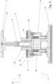
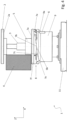
- Clamping device 1 shown has a first, upper clamping element 2 with a first clamping surface 2a and a second, lower clamping element 7f with a second clamping surface 7a. These can be moved relative to one another via a piston 3.
- the piston 3 is mounted displaceably in a cylinder 9 parallel to the vertical direction Z or generally in a stroke direction.
- the entire clamping device 1 can be arranged as a unit, for example via a foot part 11, on a substructure arrangement 12 (otherwise not shown) and can also be moved thereon.
- the piston 3 is guided in a bearing section 5.
- the second clamping element 7f is non-rotatable or at least not significantly rotatable, but is mounted with play at least in the vertical direction Z.
- a lifting element 7e is arranged below the second clamping element 7f, which here - as in particular the sectional drawings of Figures 2 and 3 show - is arranged between the second clamping element 7f and the bearing section 5.
- the lifting element 7e can be rotated relative to the second clamping element 7f about an axis of rotation parallel to the vertical axis Z.
- a lock 6 here provided, which in the example shown is designed as a lever in the form of an anti-rotation device.
- the second clamping element 7f is attached to the bearing section 5, being fixed via at least one securing section, which preferably has the shape of a set screw 7d and which engages in a recess 5a of the bearing section 5.
- the recess 5a has a vertical play, as a comparison of the thickness of the threaded pin 7d with the width of the recess 5a measured in the vertical direction Z shows. This play allows a slight movement of the clamping element 7f with its clamping surface 7a in the direction Z.
- the clamping element 7f is otherwise mounted in a rotationally fixed manner relative to the bearing section 5.
- the threaded pin 7d is pressed against the upper wall of the recess 5a, viewed in the vertical direction, which can be, for example, an annular recess.
- corresponding lifting means 7b and 5b are arranged both on the lifting element 7e and on the bearing section 5.
- these can be ramps, shafts, cams or comparable surfaces that slide over one another during a relative rotational movement between the lifting element 7e and the bearing section 5.
- the lifting element 7e is raised or lowered.
- raised areas 5b and 7b of bearing section 5 and lifting element 7e lie opposite each other, so that the maximum stroke is set here.
- a further locking recess for engaging the lever 6 can be arranged on the component 9, which corresponds to the position in which the lifting element 7b and thus also the clamping element 7f are in the lowered position, which is in the Figures 3 or 5 is shown.
- the reference number 9 denotes a cylinder to which the bearing section 5 is attached and in whose displacement 10 the piston 3 can be moved back and forth.
Landscapes
- Engineering & Computer Science (AREA)
- Mechanical Engineering (AREA)
- Jigs For Machine Tools (AREA)
Applications Claiming Priority (1)
| Application Number | Priority Date | Filing Date | Title |
|---|---|---|---|
| DE102020132391.3A DE102020132391A1 (de) | 2020-12-07 | 2020-12-07 | Spanneinrichtung |
Publications (3)
| Publication Number | Publication Date |
|---|---|
| EP4008481A1 EP4008481A1 (de) | 2022-06-08 |
| EP4008481C0 EP4008481C0 (de) | 2024-02-07 |
| EP4008481B1 true EP4008481B1 (de) | 2024-02-07 |
Family
ID=78821054
Family Applications (1)
| Application Number | Title | Priority Date | Filing Date |
|---|---|---|---|
| EP21211952.3A Active EP4008481B1 (de) | 2020-12-07 | 2021-12-02 | Spanneinrichtung |
Country Status (3)
| Country | Link |
|---|---|
| EP (1) | EP4008481B1 (pl) |
| DE (1) | DE102020132391A1 (pl) |
| PL (1) | PL4008481T3 (pl) |
Family Cites Families (7)
| Publication number | Priority date | Publication date | Assignee | Title |
|---|---|---|---|---|
| DE19938851B4 (de) | 1999-08-17 | 2005-04-07 | Gustav Weeke Maschinenbau Gmbh | Vorrichtung zum Spannen von Werkstücken |
| IT1320885B1 (it) | 2000-02-22 | 2003-12-10 | Biesse Spa | Macchina per la lavorazione di pannelli di legno o similari |
| ITBO20070141A1 (it) * | 2007-03-02 | 2008-09-03 | Grandi Progetti S R L | Macchina per la lavorazione di componenti di legno o simili |
| DE502007001909D1 (de) | 2007-05-11 | 2009-12-17 | Homag Holzbearbeitungssysteme | Werkstückspannvorrichtung |
| DE102014211433A1 (de) | 2014-06-16 | 2015-12-17 | Schaeffler Technologies AG & Co. KG | Linearaktuator |
| ES2621891T3 (es) | 2014-10-13 | 2017-07-05 | Biesse S.P.A. | Dispositivo de sujeción para sujetar una placa en una superficie de trabajo de un aparato de procesamiento, particularmente para trabajar placas de dimensiones pequeñas, en particular, placas de vidrio o de piedra y placas de madera |
| DE102014222423A1 (de) | 2014-11-03 | 2016-05-04 | Homag Holzbearbeitungssysteme Gmbh | Spannvorrichtung |
-
2020
- 2020-12-07 DE DE102020132391.3A patent/DE102020132391A1/de not_active Withdrawn
-
2021
- 2021-12-02 EP EP21211952.3A patent/EP4008481B1/de active Active
- 2021-12-02 PL PL21211952.3T patent/PL4008481T3/pl unknown
Also Published As
| Publication number | Publication date |
|---|---|
| EP4008481C0 (de) | 2024-02-07 |
| DE102020132391A1 (de) | 2022-06-09 |
| PL4008481T3 (pl) | 2024-06-10 |
| EP4008481A1 (de) | 2022-06-08 |
Similar Documents
| Publication | Publication Date | Title |
|---|---|---|
| EP3224440B1 (de) | Anordnung aus einer möbeltüre und einem hohlraum | |
| DE3531824A1 (de) | Lenkrolle | |
| EP2265784B1 (de) | Verstellvorrichtung für möbel | |
| DE102007056266A1 (de) | Presse | |
| EP3941310B1 (de) | Schiebe-schwenkmechanik für eine ablage eines möbels oder haushaltsgerätes und möbel bzw. haushaltsgerät | |
| DE102022127426A1 (de) | Regalboden mit einem bidirektionalen gleit- und kippmechanismus | |
| WO2014095338A1 (de) | Medizinischer haltearm | |
| EP3468413A1 (de) | Möbel mit auszug und erweiterungsplatte | |
| EP1336709B1 (de) | Ausziehsperre für übereinander angeordnete Schubladen | |
| EP4008481B1 (de) | Spanneinrichtung | |
| EP4385363A2 (de) | Anordnung mit antriebsvorrichtung und synchronisierungsvorrichtung für ausziehführungen für eine schublade | |
| DE1452821B1 (de) | Abkantpresse mit Einstellvorrichtung | |
| EP0622175B1 (de) | Handbetätigbare Presse | |
| AT501777B1 (de) | Schubladenführung | |
| EP2890627B1 (de) | Verriegelungsvorrichtung | |
| DE202017100035U1 (de) | Möbel mit Auszug | |
| DE3825269C3 (de) | Kurbelmechanismus für einen Hebe-Schiebedeckel eines Kraftfahrzeugs | |
| WO2005065484A1 (de) | Bremsvorrichtung für arbeitstische | |
| EP0311803A2 (de) | Ausziehtisch | |
| AT518048B1 (de) | Schubladenwand | |
| DE2430737B2 (de) | Drehtisch | |
| WO2018141658A1 (de) | Feststellvorrichtung für einen einstellbaren kraftfahrzeugsitz | |
| EP0288430A1 (de) | Sperrmechanismus, insbesondere für die Höhenverstellung von Tischplatten | |
| DE202016101290U1 (de) | Höhenverstellbarer Tisch | |
| DE202016103040U1 (de) | Möbel mit Auszug |
Legal Events
| Date | Code | Title | Description |
|---|---|---|---|
| PUAI | Public reference made under article 153(3) epc to a published international application that has entered the european phase |
Free format text: ORIGINAL CODE: 0009012 |
|
| STAA | Information on the status of an ep patent application or granted ep patent |
Free format text: STATUS: THE APPLICATION HAS BEEN PUBLISHED |
|
| AK | Designated contracting states |
Kind code of ref document: A1 Designated state(s): AL AT BE BG CH CY CZ DE DK EE ES FI FR GB GR HR HU IE IS IT LI LT LU LV MC MK MT NL NO PL PT RO RS SE SI SK SM TR |
|
| STAA | Information on the status of an ep patent application or granted ep patent |
Free format text: STATUS: REQUEST FOR EXAMINATION WAS MADE |
|
| 17P | Request for examination filed |
Effective date: 20221206 |
|
| RBV | Designated contracting states (corrected) |
Designated state(s): AL AT BE BG CH CY CZ DE DK EE ES FI FR GB GR HR HU IE IS IT LI LT LU LV MC MK MT NL NO PL PT RO RS SE SI SK SM TR |
|
| GRAP | Despatch of communication of intention to grant a patent |
Free format text: ORIGINAL CODE: EPIDOSNIGR1 |
|
| STAA | Information on the status of an ep patent application or granted ep patent |
Free format text: STATUS: GRANT OF PATENT IS INTENDED |
|
| INTG | Intention to grant announced |
Effective date: 20230824 |
|
| GRAS | Grant fee paid |
Free format text: ORIGINAL CODE: EPIDOSNIGR3 |
|
| GRAA | (expected) grant |
Free format text: ORIGINAL CODE: 0009210 |
|
| STAA | Information on the status of an ep patent application or granted ep patent |
Free format text: STATUS: THE PATENT HAS BEEN GRANTED |
|
| AK | Designated contracting states |
Kind code of ref document: B1 Designated state(s): AL AT BE BG CH CY CZ DE DK EE ES FI FR GB GR HR HU IE IS IT LI LT LU LV MC MK MT NL NO PL PT RO RS SE SI SK SM TR |
|
| REG | Reference to a national code |
Ref country code: GB Ref legal event code: FG4D Free format text: NOT ENGLISH |
|
| REG | Reference to a national code |
Ref country code: CH Ref legal event code: EP |
|
| REG | Reference to a national code |
Ref country code: IE Ref legal event code: FG4D Free format text: LANGUAGE OF EP DOCUMENT: GERMAN |
|
| REG | Reference to a national code |
Ref country code: DE Ref legal event code: R096 Ref document number: 502021002637 Country of ref document: DE |
|
| U01 | Request for unitary effect filed |
Effective date: 20240212 |
|
| U07 | Unitary effect registered |
Designated state(s): AT BE BG DE DK EE FI FR IT LT LU LV MT NL PT SE SI Effective date: 20240221 |
|
| PG25 | Lapsed in a contracting state [announced via postgrant information from national office to epo] |
Ref country code: IS Free format text: LAPSE BECAUSE OF FAILURE TO SUBMIT A TRANSLATION OF THE DESCRIPTION OR TO PAY THE FEE WITHIN THE PRESCRIBED TIME-LIMIT Effective date: 20240607 |
|
| PG25 | Lapsed in a contracting state [announced via postgrant information from national office to epo] |
Ref country code: GR Free format text: LAPSE BECAUSE OF FAILURE TO SUBMIT A TRANSLATION OF THE DESCRIPTION OR TO PAY THE FEE WITHIN THE PRESCRIBED TIME-LIMIT Effective date: 20240508 |
|
| PG25 | Lapsed in a contracting state [announced via postgrant information from national office to epo] |
Ref country code: HR Free format text: LAPSE BECAUSE OF FAILURE TO SUBMIT A TRANSLATION OF THE DESCRIPTION OR TO PAY THE FEE WITHIN THE PRESCRIBED TIME-LIMIT Effective date: 20240207 Ref country code: RS Free format text: LAPSE BECAUSE OF FAILURE TO SUBMIT A TRANSLATION OF THE DESCRIPTION OR TO PAY THE FEE WITHIN THE PRESCRIBED TIME-LIMIT Effective date: 20240507 |
|
| PG25 | Lapsed in a contracting state [announced via postgrant information from national office to epo] |
Ref country code: ES Free format text: LAPSE BECAUSE OF FAILURE TO SUBMIT A TRANSLATION OF THE DESCRIPTION OR TO PAY THE FEE WITHIN THE PRESCRIBED TIME-LIMIT Effective date: 20240207 |
|
| PG25 | Lapsed in a contracting state [announced via postgrant information from national office to epo] |
Ref country code: RS Free format text: LAPSE BECAUSE OF FAILURE TO SUBMIT A TRANSLATION OF THE DESCRIPTION OR TO PAY THE FEE WITHIN THE PRESCRIBED TIME-LIMIT Effective date: 20240507 Ref country code: NO Free format text: LAPSE BECAUSE OF FAILURE TO SUBMIT A TRANSLATION OF THE DESCRIPTION OR TO PAY THE FEE WITHIN THE PRESCRIBED TIME-LIMIT Effective date: 20240507 Ref country code: IS Free format text: LAPSE BECAUSE OF FAILURE TO SUBMIT A TRANSLATION OF THE DESCRIPTION OR TO PAY THE FEE WITHIN THE PRESCRIBED TIME-LIMIT Effective date: 20240607 Ref country code: HR Free format text: LAPSE BECAUSE OF FAILURE TO SUBMIT A TRANSLATION OF THE DESCRIPTION OR TO PAY THE FEE WITHIN THE PRESCRIBED TIME-LIMIT Effective date: 20240207 Ref country code: GR Free format text: LAPSE BECAUSE OF FAILURE TO SUBMIT A TRANSLATION OF THE DESCRIPTION OR TO PAY THE FEE WITHIN THE PRESCRIBED TIME-LIMIT Effective date: 20240508 Ref country code: ES Free format text: LAPSE BECAUSE OF FAILURE TO SUBMIT A TRANSLATION OF THE DESCRIPTION OR TO PAY THE FEE WITHIN THE PRESCRIBED TIME-LIMIT Effective date: 20240207 |
|
| PG25 | Lapsed in a contracting state [announced via postgrant information from national office to epo] |
Ref country code: SM Free format text: LAPSE BECAUSE OF FAILURE TO SUBMIT A TRANSLATION OF THE DESCRIPTION OR TO PAY THE FEE WITHIN THE PRESCRIBED TIME-LIMIT Effective date: 20240207 |
|
| PG25 | Lapsed in a contracting state [announced via postgrant information from national office to epo] |
Ref country code: CZ Free format text: LAPSE BECAUSE OF FAILURE TO SUBMIT A TRANSLATION OF THE DESCRIPTION OR TO PAY THE FEE WITHIN THE PRESCRIBED TIME-LIMIT Effective date: 20240207 |
|
| PG25 | Lapsed in a contracting state [announced via postgrant information from national office to epo] |
Ref country code: SK Free format text: LAPSE BECAUSE OF FAILURE TO SUBMIT A TRANSLATION OF THE DESCRIPTION OR TO PAY THE FEE WITHIN THE PRESCRIBED TIME-LIMIT Effective date: 20240207 |
|
| PG25 | Lapsed in a contracting state [announced via postgrant information from national office to epo] |
Ref country code: SM Free format text: LAPSE BECAUSE OF FAILURE TO SUBMIT A TRANSLATION OF THE DESCRIPTION OR TO PAY THE FEE WITHIN THE PRESCRIBED TIME-LIMIT Effective date: 20240207 Ref country code: SK Free format text: LAPSE BECAUSE OF FAILURE TO SUBMIT A TRANSLATION OF THE DESCRIPTION OR TO PAY THE FEE WITHIN THE PRESCRIBED TIME-LIMIT Effective date: 20240207 Ref country code: RO Free format text: LAPSE BECAUSE OF FAILURE TO SUBMIT A TRANSLATION OF THE DESCRIPTION OR TO PAY THE FEE WITHIN THE PRESCRIBED TIME-LIMIT Effective date: 20240207 Ref country code: CZ Free format text: LAPSE BECAUSE OF FAILURE TO SUBMIT A TRANSLATION OF THE DESCRIPTION OR TO PAY THE FEE WITHIN THE PRESCRIBED TIME-LIMIT Effective date: 20240207 |
|
| REG | Reference to a national code |
Ref country code: DE Ref legal event code: R097 Ref document number: 502021002637 Country of ref document: DE |
|
| PLBE | No opposition filed within time limit |
Free format text: ORIGINAL CODE: 0009261 |
|
| STAA | Information on the status of an ep patent application or granted ep patent |
Free format text: STATUS: NO OPPOSITION FILED WITHIN TIME LIMIT |
|
| 26N | No opposition filed |
Effective date: 20241108 |
|
| U20 | Renewal fee for the european patent with unitary effect paid |
Year of fee payment: 4 Effective date: 20241223 |
|
| PG25 | Lapsed in a contracting state [announced via postgrant information from national office to epo] |
Ref country code: MC Free format text: LAPSE BECAUSE OF FAILURE TO SUBMIT A TRANSLATION OF THE DESCRIPTION OR TO PAY THE FEE WITHIN THE PRESCRIBED TIME-LIMIT Effective date: 20240207 |
|
| REG | Reference to a national code |
Ref country code: CH Ref legal event code: PL |
|
| PG25 | Lapsed in a contracting state [announced via postgrant information from national office to epo] |
Ref country code: CH Free format text: LAPSE BECAUSE OF NON-PAYMENT OF DUE FEES Effective date: 20241231 |
|
| PG25 | Lapsed in a contracting state [announced via postgrant information from national office to epo] |
Ref country code: IE Free format text: LAPSE BECAUSE OF NON-PAYMENT OF DUE FEES Effective date: 20241202 |
|
| U20 | Renewal fee for the european patent with unitary effect paid |
Year of fee payment: 5 Effective date: 20251216 |
|
| PGFP | Annual fee paid to national office [announced via postgrant information from national office to epo] |
Ref country code: PL Payment date: 20251126 Year of fee payment: 5 |
|
| PG25 | Lapsed in a contracting state [announced via postgrant information from national office to epo] |
Ref country code: CY Free format text: LAPSE BECAUSE OF FAILURE TO SUBMIT A TRANSLATION OF THE DESCRIPTION OR TO PAY THE FEE WITHIN THE PRESCRIBED TIME-LIMIT; INVALID AB INITIO Effective date: 20211202 |