EP4008481B1 - Clamping device - Google Patents
Clamping device Download PDFInfo
- Publication number
- EP4008481B1 EP4008481B1 EP21211952.3A EP21211952A EP4008481B1 EP 4008481 B1 EP4008481 B1 EP 4008481B1 EP 21211952 A EP21211952 A EP 21211952A EP 4008481 B1 EP4008481 B1 EP 4008481B1
- Authority
- EP
- European Patent Office
- Prior art keywords
- clamping
- bearing section
- relative
- lift
- face
- Prior art date
- Legal status (The legal status is an assumption and is not a legal conclusion. Google has not performed a legal analysis and makes no representation as to the accuracy of the status listed.)
- Active
Links
- 239000002184 metal Substances 0.000 claims description 2
- 229910052751 metal Inorganic materials 0.000 claims description 2
- 239000004033 plastic Substances 0.000 claims description 2
- 229920003023 plastic Polymers 0.000 claims description 2
- 239000002023 wood Substances 0.000 claims description 2
- 239000002983 wood substitute Substances 0.000 claims description 2
- 238000006073 displacement reaction Methods 0.000 description 3
- 238000000034 method Methods 0.000 description 3
- 238000010276 construction Methods 0.000 description 1
- 230000003993 interaction Effects 0.000 description 1
- 150000002739 metals Chemical class 0.000 description 1
- 230000000284 resting effect Effects 0.000 description 1
- 230000000630 rising effect Effects 0.000 description 1
Images


Classifications
-
- B—PERFORMING OPERATIONS; TRANSPORTING
- B25—HAND TOOLS; PORTABLE POWER-DRIVEN TOOLS; MANIPULATORS
- B25B—TOOLS OR BENCH DEVICES NOT OTHERWISE PROVIDED FOR, FOR FASTENING, CONNECTING, DISENGAGING OR HOLDING
- B25B5/00—Clamps
- B25B5/06—Arrangements for positively actuating jaws
- B25B5/061—Arrangements for positively actuating jaws with fluid drive
-
- B—PERFORMING OPERATIONS; TRANSPORTING
- B25—HAND TOOLS; PORTABLE POWER-DRIVEN TOOLS; MANIPULATORS
- B25B—TOOLS OR BENCH DEVICES NOT OTHERWISE PROVIDED FOR, FOR FASTENING, CONNECTING, DISENGAGING OR HOLDING
- B25B5/00—Clamps
- B25B5/06—Arrangements for positively actuating jaws
- B25B5/067—C-clamps
-
- B—PERFORMING OPERATIONS; TRANSPORTING
- B25—HAND TOOLS; PORTABLE POWER-DRIVEN TOOLS; MANIPULATORS
- B25B—TOOLS OR BENCH DEVICES NOT OTHERWISE PROVIDED FOR, FOR FASTENING, CONNECTING, DISENGAGING OR HOLDING
- B25B5/00—Clamps
- B25B5/16—Details, e.g. jaws, jaw attachments
Definitions
- the invention relates to a clamping device according to the preamble of claim 1.
- Corresponding clamping devices which are used in particular as vertical clamps for clamping workpieces, are known from the prior art, for example from DE 101 08 134 A1 or EP 3 009 226 B1 or WO 2016/071351 A1 .
- All of these clamping devices have a first and a second clamping element with a first and second clamping surface, respectively, a workpiece can be clamped between the clamping surfaces.
- the workpiece has to be released from the clamping device, for example if it has to be re-clamped to process another side of the workpiece. Since this process is usually carried out manually, a possibility must be created to carry out this re-clamping as simply as possible, whereby the re-fixing of the workpiece usually also has to be carried out manually.
- the entire clamping device is usually moved from one location on which the clamping device is stored to another location. After moving, the clamping device must be returned to a state in which the workpiece can be clamped. It is important that the support level on the lower clamping element of the workpiece returns to the position it occupied before re-clamping.
- the object of the present invention is therefore to provide a clamping device of the type mentioned which makes this possible.
- the clamping device according to the invention which is in particular a vertical clamp, is used to clamp workpieces of all kinds, in particular those made of wood or wood substitutes, plastics, metals and the like.
- the clamping device has a first clamping element with a first clamping surface and a second clamping element with a second clamping surface facing the first clamping surface.
- the first clamping element and the second clamping element can be moved relative to one another in a clamping direction via a drive device for clamping or releasing a workpiece between the clamping surfaces.
- the clamping device according to the invention has a bearing section on which the second clamping element is attached with play and, in particular in the clamping direction, is guided displaceably within the play.
- the clamping device comprises a lifting device which is designed to move the second clamping element relative to the bearing section within the game, in particular parallel to the clamping direction.
- This relative displacement of the second clamping element relative to the bearing section within a predetermined clearance allows the support plane of the second clamping element to be displaced. If the clamping between the clamping device and the workpiece is released before this displacement, the workpiece can be clamped relatively quickly and the clamping device can be moved just as quickly. At the new position, the support level of the clamping device can then be returned to its original state.
- the bearing section is attached to a lower part.
- the lower part comprises a cylinder with a piston connected to the first clamping element, the piston being guided displaceably in the cylinder parallel to the clamping direction.
- the actual clamping process of the workpiece can be realized via this piston/cylinder arrangement.
- the cylinder can be set up in such a way that the first clamping surface is moved towards the second clamping surface by evacuating the cylinder.
- the cylinder can also be actuated by pressurization.
- the second clamping element and the bearing section are designed to be non-rotatable relative to one another. This ensures that turning the second clamping element during re-clamping does not leave any traces of friction on the workpiece.
- a lifting element which is rotatably mounted relative to the bearing section is arranged between the bearing section and the clamping element. The clamping element is raised within the game via this lifting element. The actuation of the clamping element, i.e. H. its adjustment in the lifting direction is brought about indirectly via the movement of the lifting element.
- At least one first lifting surface is arranged on the lifting element and at least one second lifting surface is arranged on the bearing section.
- These lifting surfaces are connected to each other in engagement so that they run on each other when the lifting element rotates. This is preferably done in such a way that the lifting surfaces interact with one another during relative rotation of the bearing section and the lifting element in such a way that the second clamping surface is raised or lowered relative to the first clamping surface.
- the lifting surfaces have rising and/or falling ramps relative to the plane of rotation of the bearing section and the lifting element.
- the element that interacts with the ramp on the other component is guided over the slope surface, in particular the inclined surface, of the ramp, so that the relative distance between the two components rotated relative to one another changes.
- the clamping device according to the invention has a releasable lock, in particular anti-rotation lock, which is designed to ensure a relative movement, in particular relative rotation, between the bearing section in the locked state and lifting element.
- Clamping device 1 shown has a first, upper clamping element 2 with a first clamping surface 2a and a second, lower clamping element 7f with a second clamping surface 7a. These can be moved relative to one another via a piston 3.
- the piston 3 is mounted displaceably in a cylinder 9 parallel to the vertical direction Z or generally in a stroke direction.
- the entire clamping device 1 can be arranged as a unit, for example via a foot part 11, on a substructure arrangement 12 (otherwise not shown) and can also be moved thereon.
- the piston 3 is guided in a bearing section 5.
- the second clamping element 7f is non-rotatable or at least not significantly rotatable, but is mounted with play at least in the vertical direction Z.
- a lifting element 7e is arranged below the second clamping element 7f, which here - as in particular the sectional drawings of Figures 2 and 3 show - is arranged between the second clamping element 7f and the bearing section 5.
- the lifting element 7e can be rotated relative to the second clamping element 7f about an axis of rotation parallel to the vertical axis Z.
- a lock 6 here provided, which in the example shown is designed as a lever in the form of an anti-rotation device.
- the second clamping element 7f is attached to the bearing section 5, being fixed via at least one securing section, which preferably has the shape of a set screw 7d and which engages in a recess 5a of the bearing section 5.
- the recess 5a has a vertical play, as a comparison of the thickness of the threaded pin 7d with the width of the recess 5a measured in the vertical direction Z shows. This play allows a slight movement of the clamping element 7f with its clamping surface 7a in the direction Z.
- the clamping element 7f is otherwise mounted in a rotationally fixed manner relative to the bearing section 5.
- the threaded pin 7d is pressed against the upper wall of the recess 5a, viewed in the vertical direction, which can be, for example, an annular recess.
- corresponding lifting means 7b and 5b are arranged both on the lifting element 7e and on the bearing section 5.
- these can be ramps, shafts, cams or comparable surfaces that slide over one another during a relative rotational movement between the lifting element 7e and the bearing section 5.
- the lifting element 7e is raised or lowered.
- raised areas 5b and 7b of bearing section 5 and lifting element 7e lie opposite each other, so that the maximum stroke is set here.
- a further locking recess for engaging the lever 6 can be arranged on the component 9, which corresponds to the position in which the lifting element 7b and thus also the clamping element 7f are in the lowered position, which is in the Figures 3 or 5 is shown.
- the reference number 9 denotes a cylinder to which the bearing section 5 is attached and in whose displacement 10 the piston 3 can be moved back and forth.
Landscapes
- Engineering & Computer Science (AREA)
- Mechanical Engineering (AREA)
- Jigs For Machine Tools (AREA)
Description
Die Erfindung betrifft eine Spanneinrichtung nach dem Oberbegriff des Anspruchs 1.The invention relates to a clamping device according to the preamble of
Entsprechende Spanneinrichtungen, die insbesondere als Vertikalspanner zum Einspannen von Werkstücken eingesetzt werden, sind aus dem Stand der Technik bekannt, zum Beispiel aus
Alle diese Spanneinrichtungen weisen ein erstes und ein zweites Klemmelement mit einer ersten bzw. zweiten Klemmfläche auf, wobei zwischen den Klemmflächen ein Werkstück eingeklemmt werden kann. In einigen Situationen kann es vorkommen, dass das Werkstück aus Klemmeinrichtung gelöst werden muss, etwa wenn es zur Bearbeitung einer weiteren Werkstückseite umgespannt werden muss. Da dieser Vorgang in der Regel händisch erfolgt, muss eine Möglichkeit geschaffen werden, dieses Umspannen möglichst einfach durchzuführen, wobei das erneute Fixieren des Werkstücks dabei in der Regel ebenfalls händisch durchgeführt werden muss. Zum Umspannen wird in der Regel auch die gesamte Spanneinrichtung von einem Ort, auf dem die Spanneinrichtung gelagert ist, zu einem anderen Ort versetzt. Nach dem Versetzen muss die Spanneinrichtung wieder in einen Zustand zurückgeführt werden, in welchem das Werkstück aufgespannt werden kann. Dabei ist es wichtig, dass die Auflageebene am unteren Klemmelement des Werkstücks wieder die Position einnimmt, die sie vor dem Umspannen eingenommen hat.All of these clamping devices have a first and a second clamping element with a first and second clamping surface, respectively, a workpiece can be clamped between the clamping surfaces. In some situations it may happen that the workpiece has to be released from the clamping device, for example if it has to be re-clamped to process another side of the workpiece. Since this process is usually carried out manually, a possibility must be created to carry out this re-clamping as simply as possible, whereby the re-fixing of the workpiece usually also has to be carried out manually. For re-clamping, the entire clamping device is usually moved from one location on which the clamping device is stored to another location. After moving, the clamping device must be returned to a state in which the workpiece can be clamped. It is important that the support level on the lower clamping element of the workpiece returns to the position it occupied before re-clamping.
Aufgabe der vorliegenden Erfindung ist es daher, eine Spanneinrichtung der eingangs genannten Art anzugeben, die dies ermöglicht.The object of the present invention is therefore to provide a clamping device of the type mentioned which makes this possible.
Gelöst wird diese Aufgabe durch eine Spanneinrichtung mit den Merkmalen des Anspruchs 1. Vorteilhafte Ausführungsformen finden sich in den Unteransprüchen.This task is solved by a clamping device with the features of
Die erfindungsgemäße Spanneinrichtung, bei der es sich insbesondere um einen Vertikalspanner handelt, dient zum Einspannen von Werkstücken aller Art, insbesondere solchen aus Holz oder Holzersatzstoffen, Kunststoffen, Metallen und dergleichen. Die Spanneinrichtung weist ein erstes Klemmelement mit einer ersten Klemmfläche sowie ein zweites Klemmelement mit einer der ersten Klemmfläche zugewandten zweiten Klemmfläche auf. Das erste Klemmelement und das zweite Klemmelement sind dabei relativ zueinander zum Einspannen oder Lösen eines Werkstücks zwischen den Klemmflächen über eine Antriebseinrichtung in einer Klemmrichtung bewegbar. Ferner verfügt die erfindungsgemäße Spanneinrichtung über einen Lagerabschnitt, an welchem das zweite Klemmelement mit Spiel angebracht und, insbesondere in Klemmrichtung, innerhalb des Spiels verschieblich geführt ist. Weiter ist vorgesehen, dass die Spanneinrichtung eine Hubeinrichtung umfasst, die dazu ausgelegt ist, das zweite Klemmelement relativ zum Lagerabschnitt innerhalb des Spiels, insbesondere parallel zur Klemmrichtung, zu verschieben.The clamping device according to the invention, which is in particular a vertical clamp, is used to clamp workpieces of all kinds, in particular those made of wood or wood substitutes, plastics, metals and the like. The clamping device has a first clamping element with a first clamping surface and a second clamping element with a second clamping surface facing the first clamping surface. The first clamping element and the second clamping element can be moved relative to one another in a clamping direction via a drive device for clamping or releasing a workpiece between the clamping surfaces. Furthermore, the clamping device according to the invention has a bearing section on which the second clamping element is attached with play and, in particular in the clamping direction, is guided displaceably within the play. It is further provided that the clamping device comprises a lifting device which is designed to move the second clamping element relative to the bearing section within the game, in particular parallel to the clamping direction.
Durch diese relative Verschiebung des zweiten Klemmelements relativ zum Lagerabschnitt innerhalb eines vorgegebenen Spiels lässt sich die Auflageebene des zweiten Klemmelements verlagern. Wird vor dieser Verlagerung die Klemmung zwischen Spanneinrichtung und Werkstück aufgehoben, lässt sich das Werkstück relativ schnell umspannen und die Spanneinrichtung ebenso schnell versetzen. An der neuen Position kann dann die Auflageebene der Spanneinrichtung wieder in den Ausgangszustand zurückgeführt werden.This relative displacement of the second clamping element relative to the bearing section within a predetermined clearance allows the support plane of the second clamping element to be displaced. If the clamping between the clamping device and the workpiece is released before this displacement, the workpiece can be clamped relatively quickly and the clamping device can be moved just as quickly. At the new position, the support level of the clamping device can then be returned to its original state.
Nach einer bevorzugten Ausführungsform ist der Lagerabschnitt an einem Unterteil angebracht. Dabei kann vorgesehen sein, dass das Unterteil einen Zylinder mit einem mit dem ersten Klemmelement verbundenen Kolben umfasst, wobei der Kolben im Zylinder parallel zur Klemmrichtung verschieblich geführt ist. Über diese Kolben/Zylinderanordnung kann der eigentliche Spannvorgang des Werkstücks realisiert werden. Dabei kann der Zylinder so eingerichtet sein, dass durch Evakuieren des Zylinders die erste Klemmfläche auf die zweite Klemmfläche zu bewegt wird. Es sind natürlich auch andere Antriebsarten denkbar, so kann beispielsweise auch der Zylinder durch Druckbeaufschlagung betätigt werden.According to a preferred embodiment, the bearing section is attached to a lower part. It can be provided that the lower part comprises a cylinder with a piston connected to the first clamping element, the piston being guided displaceably in the cylinder parallel to the clamping direction. The actual clamping process of the workpiece can be realized via this piston/cylinder arrangement. The cylinder can be set up in such a way that the first clamping surface is moved towards the second clamping surface by evacuating the cylinder. Of course, other types of drive are also conceivable, for example the cylinder can also be actuated by pressurization.
Erfindungsgemäß sind das zweite Klemmelement und der Lagerabschnitt relativ zueinander unverdrehbar ausgebildet. Dies sorgt dafür, dass ein Drehen des zweiten Klemmelements beim Umspannen keine Reibungsspuren auf dem Werkstück hinterlässt. Dabei ist vorgesehen, dass zwischen dem Lagerabschnitt und dem Klemmelement ein gegenüber dem Lagerabschnitt drehbar gelagertes Hubelement angeordnet ist. Über dieses Hubelement wird das Klemmelement innerhalb des Spiels angehoben. Die Betätigung des Klemmelements, d. h. dessen Verstellung in Hubrichtung, wird also indirekt über die Bewegung des Hubelements herbeigeführt.According to the invention, the second clamping element and the bearing section are designed to be non-rotatable relative to one another. This ensures that turning the second clamping element during re-clamping does not leave any traces of friction on the workpiece. It is provided that a lifting element which is rotatably mounted relative to the bearing section is arranged between the bearing section and the clamping element. The clamping element is raised within the game via this lifting element. The actuation of the clamping element, i.e. H. its adjustment in the lifting direction is brought about indirectly via the movement of the lifting element.
Dies kann zum Beispiel dadurch realisiert werden, dass eine Relativdrehung zwischen dem Hubelement und dem Lagerabschnitt ermöglicht ist, die das Anheben oder Absenken der zweiten Klemmfläche relativ zur ersten Klemmfläche bewirkt. Auch diese Wechselwirkung kann auf unterschiedliche Weise bewirkt werden. Nach einer bevorzugten Ausführungsform kann vorgesehen sein, dass am Hubelement wenigstens eine erste Hubfläche und am Lagerabschnitt wenigstens eine zweite Hubfläche angeordnet ist. Diese Hubflächen stehen miteinander im Eingriff, sodass sie bei einer Drehung des Hubelements aufeinander ablaufen. Dies geschieht bevorzugt derart, dass die Hubflächen bei relativer Drehung des Lagerabschnitts und des Hubelements miteinander derart zusammenwirken, dass die zweite Klemmfläche relativ zur ersten Klemmfläche abgehoben oder abgesenkt wird. Eine Möglichkeit dies zu realisieren, ist vorzusehen, dass die Hubflächen relativ zur Drehebene des Lagerabschnitts und des Hubelements ansteigende oder/und abfallende Rampen aufweisen. Prinzipiell genügt es, wenn lediglich eines der beiden relativ zueinander zu verdrehenden Teile über entsprechende Rampen und der jeweils andere Teil über einen entsprechenden mit den Rampen zusammenwirkenden Abschnitt, zum Beispiel Vorsprung, verfügt. Durch die Verwendung von Rampen wird das am jeweils anderen Bauteil mit der Rampe zusammenwirkende Element über die Steigungsfläche, insbesondere Schrägfläche, der Rampe geführt, sodass sich der relative Abstand der beiden relativ zueinander verdrehten Bauteile ändert.This can be realized, for example, by allowing a relative rotation between the lifting element and the bearing section, which causes the second clamping surface to be raised or lowered relative to the first clamping surface. This interaction can also be brought about in different ways. According to a preferred embodiment, it can be provided that at least one first lifting surface is arranged on the lifting element and at least one second lifting surface is arranged on the bearing section. These lifting surfaces are connected to each other in engagement so that they run on each other when the lifting element rotates. This is preferably done in such a way that the lifting surfaces interact with one another during relative rotation of the bearing section and the lifting element in such a way that the second clamping surface is raised or lowered relative to the first clamping surface. One way to realize this is to provide that the lifting surfaces have rising and/or falling ramps relative to the plane of rotation of the bearing section and the lifting element. In principle, it is sufficient if only one of the two parts to be rotated relative to one another has corresponding ramps and the other part has a corresponding section that interacts with the ramps, for example a projection. By using ramps, the element that interacts with the ramp on the other component is guided over the slope surface, in particular the inclined surface, of the ramp, so that the relative distance between the two components rotated relative to one another changes.
Damit das Absenken des zweiten Klemmelements bzw. der zweiten Klemmfläche nicht spontan und unbeabsichtigt erfolgt, kann vorgesehen sein, dass die erfindungsgemäße Spanneinrichtung eine lösbare Sicherung, insbesondere Verdrehsicherung, aufweist, die dazu ausgelegt ist, im arretierten Zustand eine Relativbewegung, insbesondere Relativdrehung, zwischen Lagerabschnitt und Hubelement zu verhindern.So that the lowering of the second clamping element or the second clamping surface does not occur spontaneously and unintentionally, it can be provided that the clamping device according to the invention has a releasable lock, in particular anti-rotation lock, which is designed to ensure a relative movement, in particular relative rotation, between the bearing section in the locked state and lifting element.
Die Erfindung wird nachfolgend anhand der
-
Figur 1 -
Figur 2Figur 1 -
Figur 3Figur 2 -
Figur 4Figur 1 -
Figur 5Figur 1
-
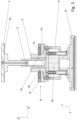
Figure 1 shows a clamping device according to the invention in a perspective view. -
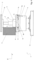
Figure 2 shows a section through the inFigure 1 clamping device shown in a first state. -
Figure 3 shows the inFigure 2 shown section in a second state. -
Figure 4 shows a side view of the inFigure 1 clamping device shown in the first state. -
Figure 5 shows a side view of theFigure 1 clamping device shown in the second state.
Die in
In der in
In der Abbildung in
Das Bezugszeichen 9 bezeichnet einen Zylinder, an welchem der Lagerabschnitt 5 befestigt ist und in dessen Hubraum 10 der Kolben 3 hin und her beweglich ist.The
In dem in
Auf die dargestellte Weise ist es mit verhältnismäßig einfacher Konstruktion möglich, dass Umspannen eines Werkstücks und das Verlagern der erfindungsgemäßen Spanneinrichtung möglichst rasch und händisch bewerkstelligen zu können.In the manner shown, with a relatively simple construction, it is possible to re-clamp a workpiece and relocate the clamping device according to the invention as quickly and manually as possible.
Claims (8)
- Clamping device (1), vertical clamp, for clamping workpieces (4), in particular those made of wood or wood substitutes, plastics, metal, comprising:a first clamping element (2) with a first clamping face (2a),a second clamping element (7f) with a second clamping face (7a) facing the first clamping face (2a), wherein the first clamping element (2) and the second clamping element (7f) are movable via a drive device relative to one another in a clamping direction (Z) for clamping or releasing a workpiece (4) between the clamping faces (2a, 7a),a bearing section (5) on which the second clamping element (7f) is attached with play, and is guided in displaceable manner within the play, in particular in the clamping direction (Z),wherein the clamping device comprises a lifting device (5b, 6, 7b, 7e) which is designed to displace the second clamping element (7f) relative to the bearing section (5) within the play, in particular parallel to the clamping direction (Z), wherein the second clamping element (7f) and the bearing section (5) are formed secured against rotation relative to one another,characterised in that a lift element (7e) which is mounted rotatable relative to the bearing section (5) is arranged between the bearing section (5) and the clamping element (7f).
- Clamping device (1) according to claim 1 characterised in that the bearing section (5) is attached to a lower part (9).
- Clamping device (1) according to claim 2 characterised in that the lower part comprises a cylinder (9) with a piston (3) which is connected to the first clamping element (2) wherein the piston (3) is guided in displaceable manner in the cylinder (9) parallel to the clamping direction (Z).
- Clamping device (1) according to claim 3 characterised in that the cylinder (9) is set up so that the first clamping face (2a) is moved up to the second clamping face (7a) by evacuating the cylinder (9).
- Clamping device (1) according to one of the preceding claims characterised in that a relative rotation between the lift element (7e) and the bearing section (5) actuates the raising or lowering of the second clamping face (7a) relative to the first clamping face (2a).
- Clamping device (1) according to claim 5 characterised in that at least a first lift face (7b) is arranged on the lift element (7e) and at least a second lift face (7b) is arranged on the bearing section (5) wherein the lift faces (5, 7b) interact with one another during relative rotation of the bearing section (5) and the lift element (7e) in such a way that the second clamping face (7a) is raised or lowered relative to the first clamping face (2a).
- Clamping device (1) according to claim 6 characterised in that the lift faces (5b, 7b) have ramps which rise and/or fall relative to the rotational plane of the bearing section (5) and lift element (7e).
- Clamping device (1) according to one of the preceding claims characterised in that it has a releasable security lock, in particular an anti- rotational lock (6), which is designed to prevent in the locked state a relative movement, in particular relative rotation, between the bearing section (5) and lift element (7e).
Applications Claiming Priority (1)
| Application Number | Priority Date | Filing Date | Title |
|---|---|---|---|
| DE102020132391.3A DE102020132391A1 (en) | 2020-12-07 | 2020-12-07 | clamping device |
Publications (3)
| Publication Number | Publication Date |
|---|---|
| EP4008481A1 EP4008481A1 (en) | 2022-06-08 |
| EP4008481C0 EP4008481C0 (en) | 2024-02-07 |
| EP4008481B1 true EP4008481B1 (en) | 2024-02-07 |
Family
ID=78821054
Family Applications (1)
| Application Number | Title | Priority Date | Filing Date |
|---|---|---|---|
| EP21211952.3A Active EP4008481B1 (en) | 2020-12-07 | 2021-12-02 | Clamping device |
Country Status (2)
| Country | Link |
|---|---|
| EP (1) | EP4008481B1 (en) |
| DE (1) | DE102020132391A1 (en) |
Family Cites Families (7)
| Publication number | Priority date | Publication date | Assignee | Title |
|---|---|---|---|---|
| DE19938851B4 (en) | 1999-08-17 | 2005-04-07 | Gustav Weeke Maschinenbau Gmbh | Device for clamping workpieces |
| IT1320885B1 (en) | 2000-02-22 | 2003-12-10 | Biesse Spa | MACHINE FOR THE PROCESSING OF WOOD PANELS OR SIMILAR |
| ITBO20070141A1 (en) * | 2007-03-02 | 2008-09-03 | Grandi Progetti S R L | MACHINE FOR PROCESSING WOOD OR SIMILAR COMPONENTS |
| EP1990135B1 (en) | 2007-05-11 | 2009-11-04 | Homag Holzbearbeitungssysteme AG | Work piece clamping device |
| DE102014211433A1 (en) | 2014-06-16 | 2015-12-17 | Schaeffler Technologies AG & Co. KG | linear actuator |
| EP3009226B1 (en) | 2014-10-13 | 2017-01-11 | Biesse S.p.A. | Clamp device for clamping a plate on a work surface of a processing apparatus, particularly for processing plates of small dimensions, in particular glass or stone plates and wood plates |
| DE102014222423A1 (en) | 2014-11-03 | 2016-05-04 | Homag Holzbearbeitungssysteme Gmbh | jig |
-
2020
- 2020-12-07 DE DE102020132391.3A patent/DE102020132391A1/en active Pending
-
2021
- 2021-12-02 EP EP21211952.3A patent/EP4008481B1/en active Active
Also Published As
| Publication number | Publication date |
|---|---|
| EP4008481C0 (en) | 2024-02-07 |
| DE102020132391A1 (en) | 2022-06-09 |
| EP4008481A1 (en) | 2022-06-08 |
Similar Documents
| Publication | Publication Date | Title |
|---|---|---|
| DE3531824A1 (en) | STEERING WHEEL | |
| DE102007056266B4 (en) | Press | |
| EP2265784B1 (en) | Adjusting device for furniture | |
| EP1336709B1 (en) | Interlock arrangement for preventing the simultaneous opening of vertically stacked drawers | |
| AT501777B1 (en) | DRAWER GUIDE | |
| EP4008481B1 (en) | Clamping device | |
| AT509331B1 (en) | EXTRACTION DEVICE FOR AT LEAST TWO REMOVABLE FURNITURE PARTS | |
| EP3468413A1 (en) | Piece of furniture with a pull-out mechanism and an extension panel | |
| DE1452821B1 (en) | Press brake with adjustment device | |
| EP0622175B1 (en) | Hand-operated press | |
| DE102022127426A1 (en) | SHELF WITH A BIDIRECTIONAL SLIDING AND TILT MECHANISM | |
| DE3825269C3 (en) | Crank mechanism for a lift and slide cover of a motor vehicle | |
| WO2018141658A1 (en) | Fixing device for an adjustable motor vehicle seat | |
| EP3941310B1 (en) | Sliding-pivoting mechanism for a rack of a piece of furniture or of a domestic appliance, and piece of furniture or domestic appliance | |
| EP1696764A1 (en) | Braking device for worktables | |
| EP1325995A2 (en) | Interlock device preventing the simultaneous opening of elements, in particular for a drawer cabinet | |
| DE202017100035U1 (en) | Furniture with pullout | |
| EP2890627B1 (en) | Locking device | |
| DE2430737B2 (en) | Turntable | |
| DE202016101290U1 (en) | Height-adjustable table | |
| EP0288430B1 (en) | Locking mechanism, especially for the height adjustment of table tops | |
| DE202016103040U1 (en) | Furniture with pullout | |
| DE602004004534T2 (en) | LOCKING SYSTEM FOR FURNITURE DRAWERS | |
| AT518048B1 (en) | drawer wall | |
| DE102007037108B4 (en) | Drive arrangement for a food-part device |
Legal Events
| Date | Code | Title | Description |
|---|---|---|---|
| PUAI | Public reference made under article 153(3) epc to a published international application that has entered the european phase |
Free format text: ORIGINAL CODE: 0009012 |
|
| STAA | Information on the status of an ep patent application or granted ep patent |
Free format text: STATUS: THE APPLICATION HAS BEEN PUBLISHED |
|
| AK | Designated contracting states |
Kind code of ref document: A1 Designated state(s): AL AT BE BG CH CY CZ DE DK EE ES FI FR GB GR HR HU IE IS IT LI LT LU LV MC MK MT NL NO PL PT RO RS SE SI SK SM TR |
|
| STAA | Information on the status of an ep patent application or granted ep patent |
Free format text: STATUS: REQUEST FOR EXAMINATION WAS MADE |
|
| 17P | Request for examination filed |
Effective date: 20221206 |
|
| RBV | Designated contracting states (corrected) |
Designated state(s): AL AT BE BG CH CY CZ DE DK EE ES FI FR GB GR HR HU IE IS IT LI LT LU LV MC MK MT NL NO PL PT RO RS SE SI SK SM TR |
|
| GRAP | Despatch of communication of intention to grant a patent |
Free format text: ORIGINAL CODE: EPIDOSNIGR1 |
|
| STAA | Information on the status of an ep patent application or granted ep patent |
Free format text: STATUS: GRANT OF PATENT IS INTENDED |
|
| INTG | Intention to grant announced |
Effective date: 20230824 |
|
| GRAS | Grant fee paid |
Free format text: ORIGINAL CODE: EPIDOSNIGR3 |
|
| GRAA | (expected) grant |
Free format text: ORIGINAL CODE: 0009210 |
|
| STAA | Information on the status of an ep patent application or granted ep patent |
Free format text: STATUS: THE PATENT HAS BEEN GRANTED |
|
| AK | Designated contracting states |
Kind code of ref document: B1 Designated state(s): AL AT BE BG CH CY CZ DE DK EE ES FI FR GB GR HR HU IE IS IT LI LT LU LV MC MK MT NL NO PL PT RO RS SE SI SK SM TR |
|
| REG | Reference to a national code |
Ref country code: GB Ref legal event code: FG4D Free format text: NOT ENGLISH |
|
| REG | Reference to a national code |
Ref country code: CH Ref legal event code: EP |
|
| REG | Reference to a national code |
Ref country code: IE Ref legal event code: FG4D Free format text: LANGUAGE OF EP DOCUMENT: GERMAN |
|
| REG | Reference to a national code |
Ref country code: DE Ref legal event code: R096 Ref document number: 502021002637 Country of ref document: DE |
|
| U01 | Request for unitary effect filed |
Effective date: 20240212 |
|
| U07 | Unitary effect registered |
Designated state(s): AT BE BG DE DK EE FI FR IT LT LU LV MT NL PT SE SI Effective date: 20240221 |