EP4007074A1 - Hermetisches anschlusselement - Google Patents
Hermetisches anschlusselement Download PDFInfo
- Publication number
- EP4007074A1 EP4007074A1 EP20844771.4A EP20844771A EP4007074A1 EP 4007074 A1 EP4007074 A1 EP 4007074A1 EP 20844771 A EP20844771 A EP 20844771A EP 4007074 A1 EP4007074 A1 EP 4007074A1
- Authority
- EP
- European Patent Office
- Prior art keywords
- fixing member
- conductor
- hermetic terminal
- insulating ring
- ring
- Prior art date
- Legal status (The legal status is an assumption and is not a legal conclusion. Google has not performed a legal analysis and makes no representation as to the accuracy of the status listed.)
- Granted
Links
Images


Classifications
-
- H—ELECTRICITY
- H01—ELECTRIC ELEMENTS
- H01R—ELECTRICALLY-CONDUCTIVE CONNECTIONS; STRUCTURAL ASSOCIATIONS OF A PLURALITY OF MUTUALLY-INSULATED ELECTRICAL CONNECTING ELEMENTS; COUPLING DEVICES; CURRENT COLLECTORS
- H01R13/00—Details of coupling devices of the kinds covered by groups H01R12/70 or H01R24/00 - H01R33/00
- H01R13/73—Means for mounting coupling parts to apparatus or structures, e.g. to a wall
- H01R13/74—Means for mounting coupling parts in openings of a panel
-
- H—ELECTRICITY
- H01—ELECTRIC ELEMENTS
- H01R—ELECTRICALLY-CONDUCTIVE CONNECTIONS; STRUCTURAL ASSOCIATIONS OF A PLURALITY OF MUTUALLY-INSULATED ELECTRICAL CONNECTING ELEMENTS; COUPLING DEVICES; CURRENT COLLECTORS
- H01R13/00—Details of coupling devices of the kinds covered by groups H01R12/70 or H01R24/00 - H01R33/00
- H01R13/02—Contact members
-
- H—ELECTRICITY
- H01—ELECTRIC ELEMENTS
- H01R—ELECTRICALLY-CONDUCTIVE CONNECTIONS; STRUCTURAL ASSOCIATIONS OF A PLURALITY OF MUTUALLY-INSULATED ELECTRICAL CONNECTING ELEMENTS; COUPLING DEVICES; CURRENT COLLECTORS
- H01R9/00—Structural associations of a plurality of mutually-insulated electrical connecting elements, e.g. terminal strips or terminal blocks; Terminals or binding posts mounted upon a base or in a case; Bases therefor
- H01R9/16—Fastening of connecting parts to base or case; Insulating connecting parts from base or case
- H01R9/18—Fastening by means of screw or nut
-
- H—ELECTRICITY
- H01—ELECTRIC ELEMENTS
- H01R—ELECTRICALLY-CONDUCTIVE CONNECTIONS; STRUCTURAL ASSOCIATIONS OF A PLURALITY OF MUTUALLY-INSULATED ELECTRICAL CONNECTING ELEMENTS; COUPLING DEVICES; CURRENT COLLECTORS
- H01R13/00—Details of coupling devices of the kinds covered by groups H01R12/70 or H01R24/00 - H01R33/00
- H01R13/02—Contact members
- H01R13/03—Contact members characterised by the material, e.g. plating, or coating materials
-
- H—ELECTRICITY
- H01—ELECTRIC ELEMENTS
- H01R—ELECTRICALLY-CONDUCTIVE CONNECTIONS; STRUCTURAL ASSOCIATIONS OF A PLURALITY OF MUTUALLY-INSULATED ELECTRICAL CONNECTING ELEMENTS; COUPLING DEVICES; CURRENT COLLECTORS
- H01R13/00—Details of coupling devices of the kinds covered by groups H01R12/70 or H01R24/00 - H01R33/00
- H01R13/40—Securing contact members in or to a base or case; Insulating of contact members
-
- H—ELECTRICITY
- H01—ELECTRIC ELEMENTS
- H01R—ELECTRICALLY-CONDUCTIVE CONNECTIONS; STRUCTURAL ASSOCIATIONS OF A PLURALITY OF MUTUALLY-INSULATED ELECTRICAL CONNECTING ELEMENTS; COUPLING DEVICES; CURRENT COLLECTORS
- H01R13/00—Details of coupling devices of the kinds covered by groups H01R12/70 or H01R24/00 - H01R33/00
- H01R13/46—Bases; Cases
- H01R13/502—Bases; Cases composed of different pieces
-
- H—ELECTRICITY
- H01—ELECTRIC ELEMENTS
- H01R—ELECTRICALLY-CONDUCTIVE CONNECTIONS; STRUCTURAL ASSOCIATIONS OF A PLURALITY OF MUTUALLY-INSULATED ELECTRICAL CONNECTING ELEMENTS; COUPLING DEVICES; CURRENT COLLECTORS
- H01R13/00—Details of coupling devices of the kinds covered by groups H01R12/70 or H01R24/00 - H01R33/00
- H01R13/46—Bases; Cases
- H01R13/52—Dustproof, splashproof, drip-proof, waterproof, or flameproof cases
- H01R13/521—Sealing between contact members and housing, e.g. sealing insert
-
- H—ELECTRICITY
- H01—ELECTRIC ELEMENTS
- H01R—ELECTRICALLY-CONDUCTIVE CONNECTIONS; STRUCTURAL ASSOCIATIONS OF A PLURALITY OF MUTUALLY-INSULATED ELECTRICAL CONNECTING ELEMENTS; COUPLING DEVICES; CURRENT COLLECTORS
- H01R13/00—Details of coupling devices of the kinds covered by groups H01R12/70 or H01R24/00 - H01R33/00
- H01R13/46—Bases; Cases
- H01R13/533—Bases, cases made for use in extreme conditions, e.g. high temperature, radiation, vibration, corrosive environment, pressure
Definitions
- the present disclosure relates to a hermetic terminal.
- Patent Document 1 discloses such a ceramic ring.
- Patent Document 1 JP 59-47916 UM-A
- a hermetic terminal includes a conductor having a pillar shape, a metal ring coaxially positioned with the conductor, an insulating ring coaxially positioned with the conductor, a flange that is disposed on the insulating ring and that divides the conductor having the pillar shape into two regions, a first fixing member configured to fix the insulating ring to the conductor, and a second fixing member configured to fix the insulating ring to the flange.
- the metal ring, the first fixing member, and the second fixing member are formed of an Fe-Co based alloy, an Fe-Co-C based alloy, an Fe-Ni based alloy, or an Fe-Ni-Co based alloy.
- the metal ring and the first fixing member are connected to each other, and the insulating ring is fixed to the conductor at a distance from the metal ring.
- a hermetic terminal includes a conductor having a pillar shape, a metal ring coaxially positioned with the conductor, an insulating ring coaxially positioned with the conductor, a flange that is disposed on the insulating ring and that divides the conductor having the pillar shape into two regions, a first fixing member configured to fix the insulating ring to the conductor, and a second fixing member configured to fix the insulating ring to the flange.
- the metal ring, the first fixing member, and the second fixing member are formed of an Fe-Co based alloy, an Fe-Co-C based alloy, an Fe-Ni based alloy, or an Fe-Ni-Co based alloy.
- the metal ring and the first fixing member are connected to each other, and the insulating ring is fixed to the conductor at a distance from the metal ring. According to such a configuration, in the hermetic terminal according to the present disclosure, even when the first fixing member and the second fixing member are each bonded to the insulating ring by a brazing material, stress remaining on the surface layer portion of the insulating ring on the second fixing member side is reduced. As a result, cracks are less likely to occur in the insulating ring, the first fixing member, and the second fixing member.
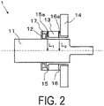
- a hermetic terminal 1 according to an embodiment of the present disclosure will be described with reference to FIGS. 1 and 2 .
- a hermetic terminal 1 according to an embodiment illustrated in FIG. 1 includes a conductor 11, a metal ring 12, an insulating ring 13, a flange 14, a first fixing member 15, a second fixing member 16, and a spacer 17.
- the conductor 11 included in the hermetic terminal 1 has a pillar shape, and the size and shape thereof are not limited as long as the conductor 11 has a pillar shape. As illustrated in FIG. 1 , the conductor 11 may have a shape such that a cylindrical portion and a quadrangular pillar shape (plate shape) portion are present. The size of the conductor 11 may be appropriately set according to a device or the like to be provided with the hermetic terminal 1.
- the conductor 11 has a shape in which a cylindrical portion and a quadrangular pillar shape (plate shape) portion are connected to each other in an axial direction, for example, the length (total length) thereof is, approximately from 200 mm to 300 mm, the outer diameter of the cylindrical portion is approximately from 90 mm to 110 mm, and the width of the quadrangular pillar shape (plate shape) portion is approximately from 80 mm to 88 mm.
- the conductor 11 is formed of, for example, copper or a copper alloy such as oxygen-free copper, tough pitch copper, or phosphorous deoxidized copper.
- the metal ring 12 included in the hermetic terminal 1 is provided so as to be coaxially positioned with the conductor 11.
- the metal ring 12 is formed of an Fe-Co based alloy, an Fe-Co-C based alloy, an Fe-Ni based alloy, or an Fe-Ni-Co based alloy.
- the alloy has an average coefficient of linear expansion from 30°C to 400°C that is lower than the average coefficient of linear expansion of copper, copper alloys, or the like constituting the conductor 11.
- the insulating ring 13 is formed of a ceramic
- the average coefficient of linear expansion thereof from 30°C to 400°C is the lowest among these alloys.
- an Fe-Ni-Co based alloy may be preferably used from the viewpoint that the risk of occurrence of cracks in the ceramic is the lowest.
- the metal ring 12 is attached to an outer peripheral surface of the conductor 11 by, for example, a silver brazing material (such as Bag-8).
- the metal ring 12 is also connected to the first fixing member 15.
- a bonding part between the conductor 11 and the first fixing member 15 can be reinforced.
- the metal ring 12 and the first fixing member 15 may be connected to each other by, for example, brazing or may simply be in contact with each other.
- the size of the metal ring 12 is not limited as long as the conductor 11 can be inserted therein.
- the outer diameter of the metal ring 12 is from 1.1 to 1.4 times the outer diameter of the conductor 11.
- the thickness of the metal ring 12 is not limited and is, for example, approximately from 2 mm to 4 mm.
- the insulating ring 13 included in the hermetic terminal 1 is provided so as to be coaxially positioned with the conductor 11.
- the flatness of each of main surfaces 13a and 13b on both sides of the insulating ring 13 is preferably 50 ⁇ m or less.
- a metallization layer (not illustrated) is formed on the main surface 13a and the first fixing member 15 and the insulating ring 13 are bonded to each other by a brazing material, a gap is less likely to be formed between the main surface 13a and the metallization layer and, consequently, the bonding reliability between the first fixing member 15 and the insulating ring 13 is improved.
- the planarity of the main surface 13b is 50 ⁇ m or less
- a metallization layer (not illustrated) is formed on the main surface 13b, and the second fixing member 16 and the insulating ring 13 are bonded to each other by a brazing material
- a gap is less likely to be formed between the main surface 13b and the metallization layer and, consequently, the bonding reliability between the second fixing member 16 and the insulating ring 13 is improved.
- the metallization layer contains, for example, from 10 mass% to 30 mass% of manganese, the balance being molybdenum.
- the parallelism of the main surface 13a with respect to the main surface 13b is preferably 0.1 mm or less.
- the insulating ring 13 is not limited as long as it is formed of an insulating material, for example, a material having a volume resistivity of 10 12 ⁇ m or more.
- Examples of such an insulating material include a ceramic containing aluminum oxide, silicon carbide, or silicon nitride as a main component. Among these materials, a ceramic containing aluminum oxide as the main component is preferably used from the viewpoint that the primary raw material is inexpensive and processing is easy.
- the crystals of aluminum oxide preferably have an average particle diameter of from 5 ⁇ m to 20 ⁇ m.
- the "main component” means a component that accounts for 80 mass% or more of the total of 100 mass% of the components constituting the ceramic.
- the identification of each component contained in the ceramic may be performed with an X-ray diffractometer using a CuK ⁇ beam, and the content of each component may be determined, for example, with an inductively coupled plasma (ICP) emission spectrophotometer or a fluorescence X-ray spectrometer.
- ICP inductively coupled plasma
- the average particle diameter of the crystals of aluminum oxide is 5 ⁇ m or more
- an area occupied by the grain boundary phase per unit area is less than that when the average particle diameter is less than 5 ⁇ m.
- thermal conductivity is improved.
- the average particle diameter is 20 ⁇ m or less
- the area occupied by the grain boundary phase per unit area is larger than that when the average particle diameter is more than 20 ⁇ m.
- the adhesiveness is enhanced due to an anchor effect of the components constituting the brazing material, thereby improving reliability, and increasing mechanical strength.
- the particle diameter of the crystals of aluminum oxide can be obtained as follows. First, diamond abrasive particles with an average particle diameter D50 of 3 ⁇ m are used for polishing with a copper grinder from the surface of the insulating ring 13 to a depth of 0.6 mm in the thickness direction. Thereafter, diamond abrasive particles with an average particle diameter D50 of 0.5 ⁇ m are used for polishing with a tin grinder.
- the polished surface obtained by these processes of polishing is heat-treated at a temperature 1480°C until the crystal grains and the grain boundary layer become distinguishable to obtain an observation surface. The heat treatment is performed for approximately 30 minutes, for example.
- the observation surface is observed with an optical microscope and captured, for example, at a magnification of 400 times.
- a range of an area of 4.8747 ⁇ 10 2 ⁇ m is defined as a measurement range.
- image analysis software for example, Win ROOF manufactured by Mitani Corporation
- the particle diameters of the crystals can be calculated and the average particle diameter can be calculated from the particle diameters.
- the particle diameter of the crystals of aluminum oxide preferably have a kurtosis of 0 or more, and the kurtosis may be 1 or more and 8 or less, from the viewpoint of suppressing a local decrease in mechanical strength.
- the kurtosis of the particle diameter of the crystals of aluminum oxide is 0 or more, variation in the particle diameter is suppressed.
- aggregation of pores is reduced, and shedding generated from the contours or interiors of the pores can be reduced, particularly if the kurtosis is 1 or more.
- the kurtosis of the particle diameter of the crystals of aluminum oxide is 8 or less, crystals having a large particle diameter and crystals having a small particle diameter are present in an appropriate ratio.
- the structure is such that crystals having a small particle diameter fill the triple junctions and, consequently, the coefficient of thermal conductivity is improved.
- the kurtosis is an index (statistical) indicating to what extent a peak and a tail of a distribution differ from those of a normal distribution.
- a distribution with a sharp peak is obtained.
- a normal distribution is obtained.
- a distribution with a rounded peak is obtained.
- the kurtosis of the particle diameter of the crystals of aluminum oxide may be obtained using the function KURT available in Excel (trade name, available from Microsoft Corporation).
- the insulating ring 13 is fixed to the conductor 11 via the first fixing member 15.
- the first fixing member 15 is formed of one of the above-described alloys, in other words, an Fe-Co based alloy, an Fe-Co-C based alloy, an Fe-Ni based alloy, or an Fe-Ni-Co based alloy.
- the alloy has an average coefficient of linear expansion from 30°C to 400°C that is lower than the average coefficient of linear expansion of copper, copper alloys, or the like constituting the conductor 11.
- the average coefficient of linear expansion of the alloy is close to the average coefficient of linear expansion of the ceramic in the above-described temperature range.
- the Fe-Ni-Co based alloy may be used from the viewpoint that the Fe-Ni-Co based alloy has the lowest average coefficient of linear expansion from 30°C to 400°C among these alloys and in a case where heat bonding is performed close to the average coefficient of linear expansion of the ceramic in the above temperature range, the risk of occurrence of cracks in the ceramic is the lowest.
- the size of the insulating ring 13 is not limited as long as the conductor 11 can be inserted therein.
- the outer diameter of the insulating ring 13 is approximately from 1.2 to 1.5 times larger than the outer diameter of the conductor 11.
- the thickness of the insulating ring 13 is also not limited and is, for example, approximately from 28 mm to 32 mm.
- the thickness of the insulating ring 13 is preferably 5 times or more the thickness of the metal ring 12, from the viewpoint that stress remaining in the surface layer portion of the insulating ring 13 on the second fixing member 16 side is reduced and, consequently, cracks are less likely to occur.
- the thickness of the insulating ring 13 is preferably 15 times or less the thickness of the metal ring 12, from the viewpoint that the material cost can be reduced.
- the insulating ring 13 is fixed to the conductor 11 at a distance from the metal ring 12.
- the distance between the metal ring 12 and the insulating ring 13 is not limited, and is appropriately set according to the size of the hermetic terminal 1.
- the distance between the metal ring 12 and the insulating ring 13 is, for example, approximately from 8 mm to 12 mm.
- the flange 14 included in the hermetic terminal 1 is installed on the insulating ring 13 and divides the conductor 11 into two regions.
- the flange 14 divides the conductor 11 into a cylindrical portion and a quadrangular pillar shape (plate shape) portion.
- the flange 14 is fixed to the insulating ring 13 via the second fixing member 16.
- the second fixing member 16 is formed of one of the above-described alloys, in other words, the Fe-Co based alloy, the Fe-Co-C based alloy, the Fe-Ni based alloy, or the Fe-Ni-Co based alloy.
- the alloy has an average coefficient of linear expansion from 30°C to 400°C that is lower than the average coefficient of linear expansion of copper, copper alloys, or the like constituting the conductor 11.
- the average coefficient of linear expansion of the alloys is close to the average coefficient of linear expansion of the ceramic in the above-described temperature range.
- the conductor 11 and the insulating ring 13 are heat-bonded to each other with a brazing material, no gap is generated between the conductor 11 and the second fixing member 16 and between the insulating ring 13 and the second fixing member 16. As a result, the reliability of the airtightness can be increased.
- the Fe-Ni-Co based alloy is preferably used from the viewpoint that the Fe-Ni-Co based alloy has the lowest average coefficient of linear expansion from 30°C to 400°C among these alloys and in a case where heat bonding is performed close to the average coefficient of linear expansion of the ceramic in the above temperature range, the risk of occurrence of cracks in the ceramic is the lowest.
- the size of the flange 14 is not limited as long as the conductor 11 can be inserted therein.
- the outer diameter of the flange 14 is from 1.5 to 2.5 times the outer diameter of the insulating ring 13.
- the thickness of the flange 14 is not limited and is, for example, approximately from 8 mm to 16 mm.
- a plurality of holes are formed in the flange 14. These holes are screw holes used to fix the hermetic terminal 1 to a device.
- the spacer 17 included in the hermetic terminal 1 is provided between the metal ring 12 and the first fixing member 15. By providing the spacer 17, the holding force of the insulating ring 13 at the outer peripheral part increases and, consequently, the reliability of the resulting hermetic terminal 1 is further improved.
- the spacer 17 is formed of, for example, a stainless steel, such as SUS304, SUS304L, SUS304ULC, SUS310ULC, or SUSXM15J1.
- the thickness of the spacer 17 is not limited and is, for example, approximately from 6 mm to 14 mm.
- a plurality of the spacers 17 are provided along a peripheral direction (circumferential direction in a case of the cylindrical conductor 11).
- the plurality of spacers 17 are preferably provided at regular intervals from the viewpoint that the outer peripheral part of the insulating ring 13 can be held relatively uniformly. As a result, the reliability of the resulting hermetic terminal 1 is further improved.
- a first groove portion may be formed on an outer peripheral surface of the spacer 17. By forming the first groove portion, even when heating and cooling are repeated, stress applied to the insulating ring 13 can be further reduced since the thermal stress is alleviated by the first groove portion.
- the first groove portion is formed, for example, along the above-described peripheral direction, and the shape thereof is a V-groove shape, a U-groove shape, or the like.
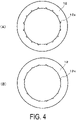
- a plurality of second groove portions 12a may be formed in the inner peripheral surface of the metal ring 12.
- the plurality of second groove portions 12a are preferably positioned at regular intervals along the inner peripheral surface, and the number of the plurality of second groove portion is, for example, 3 or more and 20 or less.
- the shape of the plurality of second groove portions 12a is, for example, a rectangular shape as illustrated in FIG. 4(a) , or a semicircular shape as illustrated in FIG. 4(b) .
- the hermetic terminal according to the present disclosure is not limited to the above-described embodiment.
- the above-described hermetic terminal 1 is provided with the spacer 17.
- the hermetic terminal according to the present disclosure need not include the spacer 17.
- the spacer 17 is a member used to further improve the effect of the hermetic terminal according to the present disclosure.
- At least one of the first fixing member 15 and the second fixing member 16 may include a sleeve having a bent portion. According to such a configuration, stress in the vicinity of the bent portion of the first fixing member 15 and the second fixing member 16 is further reduced, so that cracks are further less likely to occur.
- the inner diameter (radius) of the bent portion is not limited and may be 2 mm or more, and may be 4 mm or less, in consideration of a further superior effect of reducing stress.
- distances L 1 and L 2 from the axial center of the conductor 11 to front tip surfaces 15a and 16a of the first fixing member 15 and the second fixing member 16, respectively may be equal to each other as illustrated in FIG. 1 , or may be different from each other as illustrated in FIG. 2 .
- the distances L 1 and L 2 from the axial center of the conductor 11 to the front tip surfaces 15a and 16a of the first fixing member 15 and the second fixing member 16, respectively are preferably different from each other as illustrated in FIG. 2 from the viewpoint that cracks along the axial direction are less likely to occur in the insulating ring 13.
- a difference ⁇ between the distances L 1 and L 2 from the axial center of the conductor 11 to the front tip surfaces 15a and 16a of the first fixing member 15 and the second fixing member 16, is, for example, 3 mm or more and 6 mm or less.
- the conductor 11 has a shape such that the cylindrical portion and the quadrangular pillar shape (plate shape) portion are present.
- the shape of the conductor in the hermetic terminal according to the present disclosure is not limited as long as it is a pillar shape.
- the shape of the conductor may be appropriately designed according to a device or the like to be provided with the hermetic terminal.
Landscapes
- Connections Arranged To Contact A Plurality Of Conductors (AREA)
Applications Claiming Priority (2)
| Application Number | Priority Date | Filing Date | Title |
|---|---|---|---|
| JP2019136951 | 2019-07-25 | ||
| PCT/JP2020/028226 WO2021015189A1 (ja) | 2019-07-25 | 2020-07-21 | 気密端子 |
Publications (3)
| Publication Number | Publication Date |
|---|---|
| EP4007074A1 true EP4007074A1 (de) | 2022-06-01 |
| EP4007074A4 EP4007074A4 (de) | 2023-07-26 |
| EP4007074B1 EP4007074B1 (de) | 2025-10-01 |
Family
ID=74194181
Family Applications (1)
| Application Number | Title | Priority Date | Filing Date |
|---|---|---|---|
| EP20844771.4A Active EP4007074B1 (de) | 2019-07-25 | 2020-07-21 | Hermetisches anschlusselement |
Country Status (5)
| Country | Link |
|---|---|
| US (1) | US12046864B2 (de) |
| EP (1) | EP4007074B1 (de) |
| JP (1) | JP7257515B2 (de) |
| CN (1) | CN114175407B (de) |
| WO (1) | WO2021015189A1 (de) |
Families Citing this family (1)
| Publication number | Priority date | Publication date | Assignee | Title |
|---|---|---|---|---|
| JP7583625B2 (ja) * | 2021-01-26 | 2024-11-14 | 京セラ株式会社 | 気密端子 |
Family Cites Families (18)
| Publication number | Priority date | Publication date | Assignee | Title |
|---|---|---|---|---|
| US4296275A (en) * | 1980-06-09 | 1981-10-20 | Emerson Electric Co. | Hermetic refrigeration terminal |
| JPS5947916A (ja) | 1982-09-08 | 1984-03-17 | 三菱電機株式会社 | 中性線路保護装置 |
| JPS5947916U (ja) | 1982-09-22 | 1984-03-30 | 株式会社東芝 | セラミツクス絶縁環 |
| JPH05101731A (ja) * | 1991-10-07 | 1993-04-23 | Nippondenso Co Ltd | 接続端子 |
| JP3353570B2 (ja) * | 1995-08-21 | 2002-12-03 | 富士電機株式会社 | 平型半導体素子 |
| JP2002254166A (ja) * | 2001-02-28 | 2002-09-10 | Kyocera Corp | ロウ付け構造 |
| US6844502B2 (en) * | 2002-05-16 | 2005-01-18 | Emerson Electric Co. | Hermetically sealed current conducting terminal assembly |
| JP2005235577A (ja) | 2004-02-19 | 2005-09-02 | Kyocera Corp | 気密端子 |
| JP4423211B2 (ja) * | 2005-01-28 | 2010-03-03 | 京セラ株式会社 | ロウ付け構造および気密端子 |
| JP4684110B2 (ja) | 2006-01-30 | 2011-05-18 | 京セラ株式会社 | 気密端子 |
| US7668597B2 (en) * | 2006-03-31 | 2010-02-23 | Medtronic, Inc. | Feedthrough array for use in implantable medical devices |
| JP2013004459A (ja) | 2011-06-21 | 2013-01-07 | Toyota Industries Corp | 密閉ケースにおける導電構造 |
| WO2014083992A1 (ja) | 2012-11-29 | 2014-06-05 | 京セラ株式会社 | 電子部品収納用容器および電子装置 |
| WO2014143179A1 (en) * | 2013-03-15 | 2014-09-18 | Emerson Electric Co. | High-pressure hermetic terminal |
| CN106463309B (zh) * | 2014-06-19 | 2018-10-30 | 松下知识产权经营株式会社 | 触点装置及使用该触点装置的电磁继电器、以及触点装置的制造方法 |
| JP6756969B2 (ja) * | 2016-01-12 | 2020-09-16 | 日本電気硝子株式会社 | 封着材料 |
| JP2018005960A (ja) * | 2016-07-01 | 2018-01-11 | エヌイーシー ショット コンポーネンツ株式会社 | 接触子を有する気密端子 |
| JP6835028B2 (ja) * | 2018-03-30 | 2021-02-24 | 横河電機株式会社 | 気密端子及びセンサユニット |
-
2020
- 2020-07-21 EP EP20844771.4A patent/EP4007074B1/de active Active
- 2020-07-21 CN CN202080053629.6A patent/CN114175407B/zh active Active
- 2020-07-21 WO PCT/JP2020/028226 patent/WO2021015189A1/ja not_active Ceased
- 2020-07-21 US US17/629,506 patent/US12046864B2/en active Active
- 2020-07-21 JP JP2021534040A patent/JP7257515B2/ja active Active
Also Published As
| Publication number | Publication date |
|---|---|
| JPWO2021015189A1 (de) | 2021-01-28 |
| JP7257515B2 (ja) | 2023-04-13 |
| CN114175407B (zh) | 2024-08-20 |
| US12046864B2 (en) | 2024-07-23 |
| EP4007074B1 (de) | 2025-10-01 |
| WO2021015189A1 (ja) | 2021-01-28 |
| CN114175407A (zh) | 2022-03-11 |
| EP4007074A4 (de) | 2023-07-26 |
| US20220247101A1 (en) | 2022-08-04 |
Similar Documents
| Publication | Publication Date | Title |
|---|---|---|
| US6605868B2 (en) | Insulating substrate including multilevel insulative ceramic layers joined with an intermediate layer | |
| KR102051697B1 (ko) | 알루미늄 부재와 구리 부재의 접합 구조 | |
| KR100832826B1 (ko) | 알루미나 소성체 | |
| KR102124380B1 (ko) | 세라믹스 적층체, 세라믹스 절연 기판, 및 세라믹스 적층체의 제조 방법 | |
| US12046864B2 (en) | Hermetic terminal | |
| EP3252810A1 (de) | Leiterplatte und elektronische vorrichtung | |
| EP2833397A1 (de) | Substrat für leistungsmodul und herstellungsverfahren dafür | |
| EP2838326B1 (de) | Elektronische Vorrichtung | |
| EP4025017B1 (de) | Element zur steuerung eines elektromagnetischen feldes für einen teilchenbeschleuniger von gelanden teilchen | |
| US11472748B2 (en) | Manufacturing method for a member for a semiconductor manufacturing device and member for a semiconductor manufacturing device | |
| US12542221B2 (en) | Electromagnetic field control member | |
| US9992861B2 (en) | Heavy-wire bond arrangement and method for producing same | |
| JP7583625B2 (ja) | 気密端子 | |
| JP6858786B2 (ja) | 銅−セラミックス複合材料 | |
| EP4025016B1 (de) | Elektromagnetisches feldsteuerelement | |
| CN108698944A (zh) | 铜-陶瓷复合物 | |
| JP6777752B2 (ja) | 銅−セラミックス複合材料 | |
| WO2024004778A1 (ja) | 半導体製造装置用部材及び静電チャック装置 | |
| JP2022150445A (ja) | 絶縁継手、真空容器および粒子加速器 | |
| JP7154126B2 (ja) | ヒータ | |
| JP2008066560A (ja) | 積層型圧電アクチュエータ | |
| JP5125272B2 (ja) | ウエハプローバ用ウエハ保持体及びウエハプローバ | |
| JP2022114361A (ja) | 絶縁継手、真空容器および粒子加速器 | |
| JP2022025872A (ja) | 長尺筒状セラミック体 |
Legal Events
| Date | Code | Title | Description |
|---|---|---|---|
| STAA | Information on the status of an ep patent application or granted ep patent |
Free format text: STATUS: THE INTERNATIONAL PUBLICATION HAS BEEN MADE |
|
| PUAI | Public reference made under article 153(3) epc to a published international application that has entered the european phase |
Free format text: ORIGINAL CODE: 0009012 |
|
| STAA | Information on the status of an ep patent application or granted ep patent |
Free format text: STATUS: REQUEST FOR EXAMINATION WAS MADE |
|
| 17P | Request for examination filed |
Effective date: 20220119 |
|
| AK | Designated contracting states |
Kind code of ref document: A1 Designated state(s): AL AT BE BG CH CY CZ DE DK EE ES FI FR GB GR HR HU IE IS IT LI LT LU LV MC MK MT NL NO PL PT RO RS SE SI SK SM TR |
|
| DAV | Request for validation of the european patent (deleted) | ||
| DAX | Request for extension of the european patent (deleted) | ||
| P01 | Opt-out of the competence of the unified patent court (upc) registered |
Effective date: 20230508 |
|
| A4 | Supplementary search report drawn up and despatched |
Effective date: 20230627 |
|
| RIC1 | Information provided on ipc code assigned before grant |
Ipc: H01R 13/74 20060101ALI20230621BHEP Ipc: H01R 13/533 20060101ALI20230621BHEP Ipc: H01R 13/52 20060101ALI20230621BHEP Ipc: H01R 9/16 20060101AFI20230621BHEP |
|
| GRAP | Despatch of communication of intention to grant a patent |
Free format text: ORIGINAL CODE: EPIDOSNIGR1 |
|
| STAA | Information on the status of an ep patent application or granted ep patent |
Free format text: STATUS: GRANT OF PATENT IS INTENDED |
|
| INTG | Intention to grant announced |
Effective date: 20250429 |
|
| GRAS | Grant fee paid |
Free format text: ORIGINAL CODE: EPIDOSNIGR3 |
|
| GRAA | (expected) grant |
Free format text: ORIGINAL CODE: 0009210 |
|
| STAA | Information on the status of an ep patent application or granted ep patent |
Free format text: STATUS: THE PATENT HAS BEEN GRANTED |
|
| AK | Designated contracting states |
Kind code of ref document: B1 Designated state(s): AL AT BE BG CH CY CZ DE DK EE ES FI FR GB GR HR HU IE IS IT LI LT LU LV MC MK MT NL NO PL PT RO RS SE SI SK SM TR |
|
| REG | Reference to a national code |
Ref country code: GB Ref legal event code: FG4D Ref country code: CH Ref legal event code: F10 Free format text: ST27 STATUS EVENT CODE: U-0-0-F10-F00 (AS PROVIDED BY THE NATIONAL OFFICE) Effective date: 20251001 |
|
| REG | Reference to a national code |
Ref country code: DE Ref legal event code: R096 Ref document number: 602020059848 Country of ref document: DE |
|
| REG | Reference to a national code |
Ref country code: IE Ref legal event code: FG4D |
|
| REG | Reference to a national code |
Ref country code: NL Ref legal event code: MP Effective date: 20251001 |
|
| REG | Reference to a national code |
Ref country code: AT Ref legal event code: MK05 Ref document number: 1843544 Country of ref document: AT Kind code of ref document: T Effective date: 20251001 |
|
| PG25 | Lapsed in a contracting state [announced via postgrant information from national office to epo] |
Ref country code: NL Free format text: LAPSE BECAUSE OF FAILURE TO SUBMIT A TRANSLATION OF THE DESCRIPTION OR TO PAY THE FEE WITHIN THE PRESCRIBED TIME-LIMIT Effective date: 20251001 |