EP4005901B1 - Lagerbuchse, vorspannungsstruktur, gehäuse eines getriebemechanismus und montagestruktur von schneckengetriebe und schnecke - Google Patents
Lagerbuchse, vorspannungsstruktur, gehäuse eines getriebemechanismus und montagestruktur von schneckengetriebe und schnecke Download PDFInfo
- Publication number
- EP4005901B1 EP4005901B1 EP20846201.0A EP20846201A EP4005901B1 EP 4005901 B1 EP4005901 B1 EP 4005901B1 EP 20846201 A EP20846201 A EP 20846201A EP 4005901 B1 EP4005901 B1 EP 4005901B1
- Authority
- EP
- European Patent Office
- Prior art keywords
- worm
- bearing
- bushing
- fixed part
- housing
- Prior art date
- Legal status (The legal status is an assumption and is not a legal conclusion. Google has not performed a legal analysis and makes no representation as to the accuracy of the status listed.)
- Active
Links
Images




Classifications
-
- B—PERFORMING OPERATIONS; TRANSPORTING
- B62—LAND VEHICLES FOR TRAVELLING OTHERWISE THAN ON RAILS
- B62D—MOTOR VEHICLES; TRAILERS
- B62D5/00—Power-assisted or power-driven steering
- B62D5/04—Power-assisted or power-driven steering electrical, e.g. using an electric servo-motor connected to, or forming part of, the steering gear
- B62D5/0409—Electric motor acting on the steering column
-
- F—MECHANICAL ENGINEERING; LIGHTING; HEATING; WEAPONS; BLASTING
- F16—ENGINEERING ELEMENTS AND UNITS; GENERAL MEASURES FOR PRODUCING AND MAINTAINING EFFECTIVE FUNCTIONING OF MACHINES OR INSTALLATIONS; THERMAL INSULATION IN GENERAL
- F16H—GEARING
- F16H57/00—General details of gearing
- F16H57/12—Arrangements for adjusting or for taking-up backlash not provided for elsewhere
-
- F—MECHANICAL ENGINEERING; LIGHTING; HEATING; WEAPONS; BLASTING
- F16—ENGINEERING ELEMENTS AND UNITS; GENERAL MEASURES FOR PRODUCING AND MAINTAINING EFFECTIVE FUNCTIONING OF MACHINES OR INSTALLATIONS; THERMAL INSULATION IN GENERAL
- F16H—GEARING
- F16H57/00—General details of gearing
- F16H57/02—Gearboxes; Mounting gearing therein
- F16H57/021—Shaft support structures, e.g. partition walls, bearing eyes, casing walls or covers with bearings
- F16H2057/0213—Support of worm gear shafts
-
- F—MECHANICAL ENGINEERING; LIGHTING; HEATING; WEAPONS; BLASTING
- F16—ENGINEERING ELEMENTS AND UNITS; GENERAL MEASURES FOR PRODUCING AND MAINTAINING EFFECTIVE FUNCTIONING OF MACHINES OR INSTALLATIONS; THERMAL INSULATION IN GENERAL
- F16H—GEARING
- F16H57/00—General details of gearing
- F16H57/02—Gearboxes; Mounting gearing therein
- F16H57/021—Shaft support structures, e.g. partition walls, bearing eyes, casing walls or covers with bearings
- F16H57/022—Adjustment of gear shafts or bearings
- F16H2057/0222—Lateral adjustment
-
- F—MECHANICAL ENGINEERING; LIGHTING; HEATING; WEAPONS; BLASTING
- F16—ENGINEERING ELEMENTS AND UNITS; GENERAL MEASURES FOR PRODUCING AND MAINTAINING EFFECTIVE FUNCTIONING OF MACHINES OR INSTALLATIONS; THERMAL INSULATION IN GENERAL
- F16H—GEARING
- F16H57/00—General details of gearing
- F16H57/12—Arrangements for adjusting or for taking-up backlash not provided for elsewhere
- F16H2057/126—Self-adjusting during operation, e.g. by a spring
- F16H2057/127—Self-adjusting during operation, e.g. by a spring using springs
-
- F—MECHANICAL ENGINEERING; LIGHTING; HEATING; WEAPONS; BLASTING
- F16—ENGINEERING ELEMENTS AND UNITS; GENERAL MEASURES FOR PRODUCING AND MAINTAINING EFFECTIVE FUNCTIONING OF MACHINES OR INSTALLATIONS; THERMAL INSULATION IN GENERAL
- F16H—GEARING
- F16H55/00—Elements with teeth or friction surfaces for conveying motion; Worms, pulleys or sheaves for gearing mechanisms
- F16H55/02—Toothed members; Worms
- F16H55/22—Toothed members; Worms for transmissions with crossing shafts, especially worms, worm-gears
- F16H55/24—Special devices for taking up backlash
Definitions
- This invention relates to the technical field of the automobile steering system, especially relates to a bearing bushing, a preload structure, and an assembling structure of a worm gear and a worm.
- the housing design is mainly for internally supporting the worm gear, the worm transmission mechanism, externally connecting to the whole vehicle steering column frame and the motor. While limited by the interface size of the whole vehicle, need to design different housings according to different designs, which usually leads to a complicated structure of the housing, and a poor universality, the small end of the worm directly uses a closed/halfly closed structure, that is not facilitating to the assembling of the preload structure to some extent.
- DE102008009107B4 discloses mechanical reduction gears with worm gears and worm gears, the gear has an elastic damping ring comprising a retaining unit that retains an elastic unit for drive clearance between a wall of a retainer of a guide bearing and an outer ring of the guide bearing.
- the elastic unit is arranged in a predetermined position of the wall of the retainer, so that a force is applied over the elastic damping ring. The force presses the guide bearing in a direction, in which a center distance between an axle of a screw and an axle of a worm gear reduces.
- DE102017219395A1 discloses prestressing device for pressing a gear shaft, which has a first gear member, of a gearing against a toothing of a second gear member of said gearing comprises a housing, a bearing outer cage for receiving a bearing which rotatably supports the gear shaft, wherein the bearing outer cage is arranged in the housing, and a leaf spring which is supported by its end portions on respectively associated supporting flanks of the bearing outer cage and which is suitable for pressing with a central portion, which runs between the supporting flanks, against the bearing.
- KR20170080899A relates to a safety cover unit for an outlet.
- a hinge coupling structure is applied to a safety cover to effectively open and close an opening part of a plug insertion port of a socket.
- it is possible to prevent an electric shock accident and an inflow of foreign substances such as dust without affecting a contact point of a plug terminal hole.
- a loss can be prevented by intactly maintaining a state of being assembled to a socket during plug insertion.
- the safety cover unit for an outlet comprises: a hinge base which is fitted and coupled to a coupling hole punched on one surface of an outlet, has a hook shaft on the lower surface to be rotated, and has a hinge hole extended in the horizontal direction while being connected to both sides on the upper part; and a disk-shaped cover member which has one side coupled to the hinge hole of the hinge base to be able to be folded, opens and closes the opening part of a plug insertion hole, and has a circular arc-shaped coupling protrusion facing the same to be closely placed on the inner circumferential surface of the opening part of the plug insertion hole on the lower edge thereof.
- the invention is as defined in claim 1-15.
- the technical problem this invention solves is for overcoming the above-mentioned shortcomings of the prior art, providing a type of bearing bushing, a preload structure, a housing of transmission mechanism, and an assembling structure of a worm gear and a worm.
- the fixed part is arranged on the top surface of the bushing body, one end of the extending part that is away from the fixed part abuts against two sides of the bushing body, respectively.
- the fixed part is a C-shaped clip-shaped part.
- an outer edge of an upper piece of the C-shaped clip-shaped part is upwardly tilted to form a tilted piece, and both ends of an lower piece of the C-shaped clip-shaped part are respectively connected to the extending part.
- an end of the extending part that is away from the fixed part is bent toward the bushing body to form a bent part.
- the fixed part is fixed to the top surface of the bushing body, an end of the extending part that is away from the fixed part is tilted outward with respect to both sides of the bushing body.
- the buffer member further comprises a top elastic pad arranged on the top surface of the bushing body, the fixed part is arranged with a hole, and the hole is sleeved on the top elastic pad so that the fixed part is fixed with respect to the bushing body.
- an end of the extending part that is away from the fixed part is arranged with a contact protrusion.
- the buffer member further includes: a top elastic pad fixed on the top surface of the bearing bushing and/or side elastic pads fixed on both sides of the bearing bush.
- the side elastic member is a concave-shaped member.
- the side elastic member extends along the circumferential direction of the bushing body.
- the bushing body is a circular ring-shaped member.
- the EPSc worm end preload structure includes the bearing bushing as described above.
- the EPSc worm end preload structure further includes a bearing, and the bearing is arranged inside the bearing bushing.
- a worm gear and worm assembling structure includes the above-mentioned EPSc worm end preload structure.
- the worm gear and worm assembling structure further includes a bearing support module arranged to one end of the worm, the EPSc worm end preload structure is arranged in the bearing support module and is arranged between the worm and the bearing support module.
- the bearing support module is arranged to the small end of the worm.
- the fixed part is arranged on the top surface of the bushing body, and one end of the extending part that is away from the fixed part abuts against both sides of the bushing body respectively; the fixed part is fixed to the bearing support module.
- the fixed part is a C-shaped clip-shaped part; the fixed part clamps to the upper part of the bearing support module.
- the fixed part is fixed to the top surface of the bushing body, and an end of the extending part that is away from the fixed part is tilted outward with respect to both sides of the bushing body;
- Two sides of an inner hole of the bearing support module are formed into insert holes, the bearing bushing is arranged in the inner hole, the extending part is inserted into the insert holes, and the top surface of the bearing bushing abuts against the top surface of the inner hole.
- the positive progressive effect of the present invention is that the transmission mechanism housing is arranged with an end cover and a bearing support module for connecting with the whole vehicle which is separated from the housing module that accommodates the worm gear and the worm, this realizes assemblies of different whole vehicles wherein only needs to change the end cover and the bearing mount support module, does not need to redesign the entire housing, which facilitates the assembling of the whole vehicle and reduces the production cost.
- the present invention adjusts the location of the preload device from the big end of the worm to the small end of the worm, and redesigns the bearing bushing of the preload device, which greatly reduces the requirements for parts and components processing technique, the elastic coefficient of the leaf spring is also easier to control, so that the preload effect of the worm gear and the worm can be better adjusted, the friction torque can be reduced, and the risk of the engaging noise of the worm gear and the worm under various working conditions can be reduced, while the detachable worm gear and worm housing facilitates the assembling of the whole vehicle, when assembling different whole vehicles, only needs to change the plastic end cover and the bearing mount support module, does not need to redesign the entire housing, which reduces the production cost.
- the bearing bushing provides a special preload force as shown in Figure 5 through the deformation of the extending part of the spring piece relative to the fixed part, which enhances the robustness of the preload design, reduces the friction torque, and reduces the engaging noise of the worm gear and the worm under various working conditions.
- the EPSc worm end preload structure and the worm gear and worm assembling structure have the same effect as described above.
- the spring piece contacts the housing at one end and presses the bush at one end, when the worm swings, the spring piece is deformed, which exerts a preload force, so the worm is always taking a radial force that presses against the worm gear, to enhance the robustness of the preload design, reduce the friction torque, and reduce the engaging noise of the worm gear and the worm under various working conditions.
- this embodiment provides a bearing bushing of an improved EPSc worm end preload structure, including a housing, rubber pads and a spring piece, the rubber pads are divided into a top rubber pad 11 and side rubber pads 12.
- the top rubber pad 11 is injection molded on the top of the housing 13
- the side rubber pads 12 are injection molded on both sides of the housing 13
- the spring piece 14 is arranged on the outer side surface of the housing 13 above the side rubber pads 12;
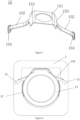
- the spring piece 14 is formed by a C-shaped clip-shaped part 141 and two wings 142, the outer edge of the upper piece of the C-shaped clip-shaped part 141 is upwardly tilted to form a tilted piece, two ends of the lower piece of the C-shaped clip-shaped part 141 are respectively connected to the top ends of the two wings 142, the bottom ends of the two wings 142 are bent inward to form a bend part 144, and the bend part 144 is tightly attached to the housing 13, so that the C-shaped clip-shaped part 141 is suspended above the housing
- the C-shaped clip-shaped part 141 of the spring piece 14 in this embodiment is embedded and fixed on housing 2.
- the ends of worm 3 that clamp the housing 2 comprise a big end 32 and a small end 31, a pendulum bearing 4 is sleeved on the big end 32, between the pendulum bearing 4 and the big end 32 is an interference fit, the small end 31 is installed with a deep groove ball bearing 5 in the interference press-fit.
- the deep groove ball bearing 5 is then sleeved into the bearing bush 9, the outer edge of the pendulum bearing 4 is fixed on the housing 2 of the actuating device, the worm 3 can swing back and forth with the pendulum bearing 4 as the pivot joint, the pendulum bearing 4 has a large radial clearance, and the inner ring ball track adopts a special arc transition, during engaging of the worm gear and the worm, the pendulum bearing 4 will effectively guide the worm 3 to swing at a certain angle on its axis relative to the housing 2.
- the top rubber pad 11 in this embodiment is disc-shaped, the side rubber pad 12 is concave-shaped, when the worm 3 swings greatly from side to side, protrusions at both ends of the side rubber pad 12 first contact the housing 2, since the contact area is small, the rigidity is small, it provides the first buffer step for the worm 3.
- the middle part of the rubber finally presses the housing over a large area to provide a buffer of greater rigidity, thereby reducing the risk of noise that the worm 3 hits the housing in two steps, meanwhile providing a rigid limiting point for the worm 3 to swing.
- the bearing bushing 1 swings accordingly, when the worm 3 shakes left and right, the side rubber pads 12 and the spring piece 14 both limit and buffer the movement, when the worm 3 shakes up and down, the upper end of the spring piece 14 abuts the housing 2, two ends press on the bearing bushing 1, deformed under force, provides damping, and limits its tendency to move away from the worm gear.
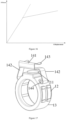
- the leaf piece 14 in this embodiment is a leaf spring, the relationship between its elastic force and displacement (compression amount) is presented by the solid line in Figure 5 .
- the difference between the curve for spring force and displacement of the leaf spring and curves of other springs is that, when the compression displacement reaches a certain value, the compressive stiffness will decrease, which can ensure that the spring preload force is basically stable within a relatively large displacement range.
- the compression amount fluctuates greatly in relative when the spring is installed in place. If using a regular spring for preloading, the provided preload force will also fluctuate greatly in relative, and the preset preload force cannot be well achieved, as shown by the dashed line in Figure 5 .
- the preload force can be kept within a predetermined range when the assembling tolerance is large.
- the shape of the spring piece 14 is specially designed, so the force bearing direction of the bearing bushing 1 always points towards the central axis of the worm 3.
- the spring piece 14 can compress the bearing bushing 1, not only from the top direction, but also from the side directions to compress the bearing bush 9 through deformation, allowing the worm 3 to swing freely within a certain range, and finely limiting the shaking of the worm 3, providing damping.
- the required preload force can be adjusted by adjusting the stiffness of the spring piece 14, so as to meet the requirements for engaging of various types of worm gears and worms.
- this embodiment provides a bearing bushing using on a worm end radial preload structure of an EPSc, which comprises a housing 13, rubber pads, and a spring piece 15.
- the rubber pads comprise a top rubber pad 11 and side rubber pads 12, the top rubber pad 11 is injection molded on the top of the housing 13, the side rubber pads 12 are injection molded on both sides of the housing 13, the spring piece 15 is embedded and fixed on the top of the housing 13;
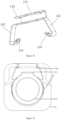
- the spring piece 15 includes a middle part 151 and two wings 152, two wings 152 are respectively fixed on both sides of the middle part 151 by a transition area 153, the middle part 151 is a plane rectangle, the two wings 152 are downwardly inclined strips, and the free ends of the two wings 152 are respectively fixed with an inward curving spring piece 154.
- the ends of the worm 1 comprise a large end 32 and a small end 31, a pendulum bearing 4 is sleeved on the large end 32, in between the pendulum bearing 4 and the large end 32 is an interference fit, and a bearing 5 is sleeved on the small end 31, the bearing bushing 1 is sleeved on the outer edge of the bearing 5, and the outer edge of the pendulum bearing 4 is fixed on the housing 2 of the actuating device, the pendulum bearing 4 has a large radial clearance, and the inner ring ball track adopts a special arc transition, during engaging of the worm gear and the worm, the pendulum bearing 4 will effectively guide the worm to swing at a certain angle on its axis relative to the housing 2.
- the top of the housing 13 is arranged with a protrusion platform, and the middle part 151 of the spring piece 15 is fixed on the protrusion platform by the top rubber pad 11.
- the top rubber pad 11 is disc-shaped.
- the side rubber pad 12 is concave-shaped, when the worm swings from side to side, protrusions at both ends of the side rubber pad 12 first contact the housing 13, since the contact area is small, the rigidity is small, it provides the first buffer step for the worm.
- the middle part of the side rubber pad 12 finally presses the housing 13 over a large area to provide a buffer of greater rigidity, thereby reducing the risk of noise that the worm hits the housing in two steps, meanwhile providing a rigid limiting point for the worm to swing.
- the spring piece 15 in this embodiment is a leaf spring, the relationship between its elastic force and displacement is shown in Figure 10 , the difference between the curve for elastic force and displacement of the leaf spring and curves of other springs is that, when the compression displacement reaches a certain value, the compression stiffness will decrease, as shown by the solid line in Figure 10 .
- This can ensure that the spring preload force is basically stable within a relatively large displacement range.
- the compression amount fluctuates greatly in relative when the spring is installed in place. If using a regular spring for preloading, the provided preload force will also fluctuate greatly in relative, and the preset preload force cannot be well achieved, as shown by the dashed line in Figure 10 .
- the preload force can be kept within a predetermined range when the assembling tolerance is large.
- the bearing bushing 1 is completely sleeved into the outer ring of the worm small end bearing 5, then installed into the housing 2 together, when the worm swings, the bearing bushing 1 swings accordingly, when the worm shakes left and right, the side rubber pad 12 and the spring piece 15 both limit and buffer the movement; when the worm shakes up and down, the upper end of the spring piece 15 abuts the housing 2, two ends press on the housing 13, deformed under force, provides damping, limits its tendency to move away from the worm gear.
- the spring piece 15 after the shape of the spring piece 15 is matched with the housing 13, it can not only provide the preload force for swinging up and down, but also provide the preload force for swinging left and right, allowing the worm to swing freely within a certain range, also finely limiting the shaking of the worm, providing damping, meanwhile, the required preload force can be adjusted by adjusting the stiffness of the spring piece 15, so as to meet the requirements for engaging of various types of worm gears and worms.
- the plastic end cover 8 is installed and fixed on the worm gear housing 91, the bearing support module 2 is connected to the other end of the worm housing 33 by screws, the worm gear 9 is installed in the worm gear housing 91, the worm 3 is installed in the worm housing 33, the worm gear 9 and the worm 3 are engaged with each other, the connecting frame housing 7 is connected with the steering column frame, one end of the worm 3 is arranged with a preload structure, and a pendulum bearing 4 is sleeved on the other end of the worm 3.
- the plastic end cover 8 is arranged with a mounting through-hole, a metal ring 81 is installed in the mounting through-hole by interference press-fit, a self-tapping screw penetrates the metal ring 81 to fix the plastic end cover 8 on the surface of the worm gear housing 91.
- preload structure includes a bearing 5, a bearing bushing 1, the bearing 5 is sleeved on the worm 3, the bearing bushing 1 is sleeved on the bearing 5.
- the bearing bushing 1 includes a housing (bushing body) 13, rubber pads, and a spring piece 15, the rubber pads comprise a top rubber pad 11 and side rubber pads 11-4, the top rubber pad 11 is injection molded on the top of the housing 11-1, side rubber pads 11-4 are injection molded on both sides of the housing 13, the spring piece 15 is installed on the housing 13. Rubber pads and spring pieces are all buffer members for applying the buffer effect. In this embodiment, rubber pads are used, but optionally, elastic pads of other alternative materials can also be used to achieve buffer on the top and both sides of the bearing bushing.
- the spring piece is arranged between the housing 13 and the bearing support module 2.
- a spring piece 15 is arranged on the top of a housing 13, the spring piece 15 comprises an extending part and a fixed part, the extending part obliquely extends downward from two opposite sides of the fixed part.
- the spring piece 15 includes a middle part 11-2-1a (fixed part) and two wings 152 (extending part), two wings 152 are respectively fixed on both sides of the the middle part 151 by the transition area, the middle part 151 is a plane rectangle, the two wings 152 are downwardly inclined strips, and the free ends of the two wings 152 (one end of the extending part which is far away from the fixed part) are respectively fixed with an inward curving spring piece 15.
- the inward curving spring piece forms a protrusion (contact protrusion) on the surface which faces the housing 13 through inward curving, through the protrusion the contact area between the inward curving spring piece 15- and the housing is reduced, which reduces the friction between them, facilitates the sliding of the inward curving spring piece 15- relative to the housing.
- the free ends of the two wings 152 are tilted outward relative to two sides of the housing 13.
- the middle part 151 of the spring piece 15 is fixed on the protrusion platform by the top rubber pad 11. Specifically, the middle part 151 of the spring piece 15 is arranged with a hole, the spring piece 15 is fixed to the top rubber pad 11 through a fit between the top rubber pad 11 and the hole.
- the top rubber pad 11 is disc-shaped, the side rubber pad is concave-shaped, when the worm swings greatly from side to side, protrusions at both ends of the side rubber pad 12 first contact the housing, since the contact area is small, the rigidity is small, it provides the first buffer step for the worm, when the worm continues to swing, the middle part of the side rubber pad finally presses the housing over a large area to provide a buffer of greater rigidity, thereby reducing the risk of noise that the worm hits the housing in two steps, meanwhile providing a rigid limiting point for the worm to swing.
- the side rubber pad 12 extends along the circumferential direction of the housing 13, the housing 13 is a circular ring member.
- the spring piece 15 in this embodiment is a leaf spring, the relationship between its elastic force and displacement (the amount of compression or the amount of deformation) is shown in Figure 16 , the difference between the curve for elastic force and displacement of the leaf spring and curves of other springs is that, when the compression displacement reaches a certain value, the compression stiffness will decrease, as shown by the solid line in Figure 16 .
- This can ensure that the spring preload force is basically stable within a relatively large displacement range.
- the compression amount fluctuates greatly in relative when the spring is installed in place.
- the provided preload force will also fluctuate greatly in relative, and the preset preload force cannot be well achieved, as shown by the dashed line in Figure 16 .
- the preload force can be kept within a predetermined range when the assembling tolerance is large.
- the inner hole of the bearing support module 2 is an adjustable hole, which can be inner holes with complicated shapes as a square hole, a round hole, etc.
- the preload structure is arranged in the bearing support module 2, and is arranged between the worm and the bearing support module 2. As shown in Figure 15 , two sides of the inner hole of the bearing support module are formed into insert holes 21, the bearing bushing is arranged in the inner hole, two wings 152 are inserted into the insert holes 21, the top surface of the bearing bushing abuts against the top surface of the inner hole, therefore defining the spring piece 15 between the upper part of the bearing support module 2 and the housing 13.
- insert holes 21 obliquely extend downward, and their inclined angles are different to inclined angles of the two wings 152 of the spring piece 15, which is, between extending directions of the insert holes 21 and extending directions of the two wings 152 are certain angles, so that, when the housing 13 moves left and right or moves up and down, the two wings 152 are deformed due to abutment against inner walls of the insert holes 21, thus achieving the buffer to the bearing bushing in the up-down direction and left-right direction.
- the metal ring is firstly press-fitted with the plastic end cover for an interference fit, then three self-tapping screws are used to fix the plastic end cover with the worm gear housing, the press-fitted metal ring is mainly used to bear the tightening torque of the self-tapping screws, and protect the plastic end cover.
- the worm gear of this embodiment does not require customized processing of threaded holes on the housing, as well as uses different plastic end cap designs to meet interface sizes of different vehicles, so that the housing body can remain unchanged and be used in various projects.
- the bearing support module is fixed to the housing body by three or four screws, in such a way, while the outer structure of the housing remains unchanged, the inner hole shapes of the adjustable bearing support module are selectively adjusted according to the adopted bearing, so that, the bearing assembled inside obtains preload forces in different directions to restrain the worm gear and worm transmission mechanism.
- the housing of this embodiment adopts a modular design, different models can match with different plastic end covers and bearing mount support modules, while the housing body remains unchanged, which greatly reduces design variants, reduces labor costs and parts procurement costs, flexiblizes designs, facilitates managements, since the housing body remains unchanged, it can be applied to various projects, greatly reduces the development cycle and shortens the project cycle; changing the entire complex housing design into the current modular housing composed by several small parts, can simplify the supplier's mold design, greatly reduces the difficulty of housing manufacturing, greatly improves the rate of qualified products, and improves the quality, stability and robustness; the detachable bearing mount support module can provide various preload forces to the bearing by changing the design structure of the support, and facilitates the assembling of the bearing mount.
- the pendulum bearing in this embodiment has a large radial clearance, and the inner ring ball track adopts a special arc transition, during engaging of the worm gear and the worm, the pendulum bearing will effectively guide the worm to swing at a certain angle on its axis relative to the housing.
- the bearing bushing is completely sleeved into the outer ring of the worm small end bearing, then installed into the housing together, when the worm swings, the bearing bushing swings accordingly, when the worm shakes left and right, the side rubber pad and the spring piece both limit and buffer the movement; when the worm shakes up and down, the upper end of the spring piece abuts the housing, two ends press on the housing, deformed under force, provides damping, limits its tendency to move away from the worm gear.
- adjusting the location of the preload device from the big end of the worm to the small end of the worm may achieve a better preload effect to the worm gear and the worm. While the large end of the worm is installed with a pendulum bearing.
- This embodiment provides a worm gear and worm assembling structure, which is almost the same as the worm gear and worm assembling structure of embodiment 3, which has differences on:
- the spring piece 14 of this embodiment is formed by a C-shaped clip-shaped part 141 (fixed part) and two-wing inclined skirts 142 (extending parts), the outer edge of the upper piece of the C-shaped clip-shaped part 141 is upwardly tilted to form a tilted piece 143, two ends of the lower piece of the C-shaped clip-shaped part 141 are respectively connected with top ends of the two-wing inclined skirts 142, the bottom ends of the two-wing inclined skirts 142 are bent inward to form a bent part 144.
- the bent part is a smooth hook-shaped structure.
- a further buffer can be formed, and no sharp part that damages the bushing body is formed.
- the bottom ends of the two-wing inclined skirts 142 may not form a bent part, while it may also be in the shape of a flat plate, and so on, which does not affect the implementation of the present invention.
- the C-shaped clip-shaped part 141 is arranged above the top surface of the bushing body.
- the C-shaped clip-shaped part 141 of the spring piece 14 is embedded and fixed on the housing. Through the elastic clamping between the upper piece and the lower piece of the C-shaped clip-shaped part 141, the spring piece 14 is tightly clamped to the housing (bearing support module 2).
- the upper part of the bearing support module 2 can also be formed with a dent section for clamping the C-shaped clip-shaped part 141, and the dent section can further achieve the limit of the C-shaped clip-shaped part 141 in the left-right direction.
- the bent part 144 is tightly attached to the housing 13, so that the C-shaped clip-shaped part 141 is suspended and fixed above the top rubber pad 11.
- the structure of the spring piece shown in embodiment 3 or 4 can be selectively adopted, the spring piece shown in embodiments 3 and 4 can not only provide the preload force for swinging up and down, but also provide the preload force for swinging left and right, allowing the worm to swing freely within a certain range, also finely limiting the shaking of the worm, providing damping, meanwhile, the required preload force can be adjusted by adjusting the stiffness of the spring piece, so as to meet the requirements for engaging of various types of worm gears and worms.
Landscapes
- Engineering & Computer Science (AREA)
- General Engineering & Computer Science (AREA)
- Mechanical Engineering (AREA)
- Chemical & Material Sciences (AREA)
- Combustion & Propulsion (AREA)
- Transportation (AREA)
- Gear Transmission (AREA)
- Power Steering Mechanism (AREA)
- Gears, Cams (AREA)
Claims (15)
- Lagerbuchse (1), wobei die Lagerbuchse (1) Folgendes umfasst: einen Buchsenkörper (13) und ein damit verbundenes Pufferelement;das Pufferelement ein Federstück (14,15) umfasst, das Federstück (14,15) auf der Oberseite des Buchsenkörpers angeordnet ist, dadurch gekennzeichnet, dassdas Federstück (14,15) ein sich erstreckendes Teil und ein festes Teil (141,151) umfasst, wobei sich das sich erstreckende Teil von zwei gegenüberliegenden Seiten des festen Teils schräg nach unten erstreckt;das Pufferelement ferner Folgendes beinhaltet: ein oberes elastisches Polster (11), das an der Oberseite der Lagerbuchse (1) befestigt ist, und/oder seitliche elastische Polster (12), die an beiden Seiten der Oberseite der Lagerbuchse (1) befestigt sind.
- Lagerbuchse (1) nach Anspruch 1, wobei das feste Teil über der Oberseite des Buchsenkörpers angeordnet ist bzw. ein Ende des sich erstreckenden Teils, das von dem festen Teil abseits ist, an beiden Seiten des Buchsenkörpers anliegt.
- Lagerbuchse (1) nach Anspruch 2, wobei das feste Teil ein C-förmiges, bügelförmiges Teil (141) ist.
- Lagerbuchse (1) nach Anspruch 3, wobei ein äußerer Rand eines oberen Teils des C-förmigen, bügelförmigen Teils (141) nach oben gekippt ist, um ein gekipptes Teil auszubilden, und beide Enden eines unteren Teils des C-förmigen, bügelförmigen Teils (141) jeweils mit dem sich erstreckenden Teil verbunden sind.
- Lagerbuchse (1) nach Anspruch 2, wobei ein Ende des sich erstreckenden Teils, das von dem festen Teil abseits ist, in Richtung des Buchsenkörpers gebogen ist, um ein gebogenes Teil (144) auszubilden.
- Lagerbuchse (1) nach Anspruch 1, wobei das feste Teil an der Oberseite des Buchsenkörpers befestigt ist, ein Ende des sich erstreckenden Teils, das von dem festen Teil abseits ist, in Bezug auf beide Seiten des Buchsenkörpers nach außen geneigt ist.
- Lagerbuchse (1) nach Anspruch 6, wobei das Pufferelement ferner das obere elastische Polster (11) umfasst, das auf der Oberseite des Buchsenkörpers angeordnet ist, das feste Teil mit einem Loch angeordnet ist und das Loch auf dem oberen elastischen Polster (11) so umhüllt ist, dass das feste Teil in Bezug auf den Buchsenkörper befestigt ist.
- Lagerbuchse (1) nach Anspruch 1, wobei ein Ende des sich erstreckenden Teils, das von dem festen Teil abseits ist, mit einem Kontaktvorsprung angeordnet ist.
- Lagerbuchse (1) nach Anspruch 1, wobei die seitlichen elastischen Polster (12) konkav geformt sind.
- Lagerbuchse (1) nach Anspruch 9, wobei sich die seitlichen elastischen Polster (12) entlang der Umfangsrichtung des Buchsenkörpers erstrecken.
- Schneckenende-Vorspannstruktur für elektrisch angetriebene Lenkprodukte, wobei die Schneckenende-Vorspannstruktur die Lagerbuchse (1) nach einem der Ansprüche 1-10 umfasst; die Schneckenende-Vorspannstruktur ferner ein Lager (5) beinhaltet und das Lager (5) im Inneren der Lagerbuchse (1) angeordnet ist.
- Schneckengetriebe- und Schneckenmontagestruktur, wobei sie die Schneckenende-Vorspannstruktur nach Anspruch 11 umfasst;
die Schneckengetriebe- und Schneckenmontagestruktur ferner ein Lagerträgermodul (2) beinhaltet, das an einem Ende der Schnecke (3) angeordnet ist, wobei die Schneckenende-Vorspannstruktur in dem Lagerträgermodul (2) angeordnet ist und zwischen der Schnecke (3) und dem Lagerträgermodul (2) angeordnet ist. - Schneckengetriebe- und Schneckenmontagestruktur nach Anspruch 12, wobei das feste Teil an der Oberseite des Buchsenkörpers befestigt ist, ein Ende des sich erstreckenden Teils, das von dem festen Teil abseits ist, in Bezug auf beide Seiten des Buchsenkörpers nach außen geneigt ist;
zwei Seiten eines inneren Lochs des Lagerträgermoduls (2) in Einstecklöchern (21) ausgebildet sind, die Lagerbuchse (1) in dem inneren Loch angeordnet ist, das sich erstreckende Teil in die Einstecklöcher (21) eingesteckt ist und die Oberseite der Lagerbuchse (1) an der Oberseite des inneren Lochs anliegt. - Schneckengetriebe- und Schneckenmontagestruktur nach Anspruch 12, wobei das feste Teil, das an der Oberseite des Buchsenkörpers angeordnet ist, bzw. ein Ende des sich erstreckenden Teils, das von dem festen Teil abseits ist, an zwei Seiten des Buchsenkörpers anliegt;
das feste Teil an dem Lagerträgermodul (2) befestigt ist. - Schneckengetriebe- und Schneckenmontagestruktur nach Anspruch 14, wobei das feste Teil ein C-förmiges, bügelförmiges Teil (141) ist;
das feste Teil an das obere Teil des Lagerträgermoduls (2) geklemmt ist.
Applications Claiming Priority (5)
| Application Number | Priority Date | Filing Date | Title |
|---|---|---|---|
| CN201921212612 | 2019-07-30 | ||
| CN201921212059 | 2019-07-30 | ||
| CN201921212066 | 2019-07-30 | ||
| CN201921212057 | 2019-07-30 | ||
| PCT/CN2020/094644 WO2021017643A1 (zh) | 2019-07-30 | 2020-06-05 | 轴承衬套、预紧结构、传动机构壳体及蜗轮蜗杆装配结构 |
Publications (4)
| Publication Number | Publication Date |
|---|---|
| EP4005901A1 EP4005901A1 (de) | 2022-06-01 |
| EP4005901A4 EP4005901A4 (de) | 2023-06-28 |
| EP4005901C0 EP4005901C0 (de) | 2024-10-16 |
| EP4005901B1 true EP4005901B1 (de) | 2024-10-16 |
Family
ID=74230062
Family Applications (1)
| Application Number | Title | Priority Date | Filing Date |
|---|---|---|---|
| EP20846201.0A Active EP4005901B1 (de) | 2019-07-30 | 2020-06-05 | Lagerbuchse, vorspannungsstruktur, gehäuse eines getriebemechanismus und montagestruktur von schneckengetriebe und schnecke |
Country Status (4)
| Country | Link |
|---|---|
| EP (1) | EP4005901B1 (de) |
| ES (1) | ES3006449T3 (de) |
| HU (1) | HUE070323T2 (de) |
| WO (1) | WO2021017643A1 (de) |
Families Citing this family (2)
| Publication number | Priority date | Publication date | Assignee | Title |
|---|---|---|---|---|
| CN113775733B (zh) * | 2021-09-26 | 2025-02-14 | 广东普天红智能科技有限公司 | 一种改进型缓冲式车位锁减速机 |
| CN115419705A (zh) * | 2022-09-30 | 2022-12-02 | 天津德科智控股份有限公司 | 一种蜗轮蜗杆间隙消除机构 |
Family Cites Families (8)
| Publication number | Priority date | Publication date | Assignee | Title |
|---|---|---|---|---|
| JP2006044430A (ja) * | 2004-08-03 | 2006-02-16 | Favess Co Ltd | 電動パワーステアリング装置 |
| JP4501068B2 (ja) * | 2004-10-14 | 2010-07-14 | 株式会社ジェイテクト | 電動パワーステアリング装置 |
| DE102008009107B4 (de) * | 2008-02-14 | 2010-06-17 | Jtekt Europe | Mechanisches Untersetzungsgetriebe mit Schnecke und Schneckenrad |
| KR101423949B1 (ko) * | 2013-09-02 | 2014-08-01 | 한국델파이주식회사 | 전동식 파워 스티어링 장치 |
| KR102101664B1 (ko) * | 2015-12-31 | 2020-04-27 | 남양넥스모 주식회사 | 전동식 파워 스티어링장치의 베어링 홀더 구조체 |
| JP6876249B2 (ja) * | 2017-04-19 | 2021-05-26 | 株式会社ジェイテクト | ウォーム減速機および電動パワーステアリング装置 |
| DE102017219395A1 (de) * | 2017-10-27 | 2019-05-02 | Volkswagen Aktiengesellschaft | Vorspanneinrichtung |
| CN207333665U (zh) * | 2017-10-31 | 2018-05-08 | 长城汽车股份有限公司 | 蜗轮蜗杆传动机构的间隙补偿结构、转向系统和车辆 |
-
2020
- 2020-06-05 WO PCT/CN2020/094644 patent/WO2021017643A1/zh not_active Ceased
- 2020-06-05 ES ES20846201T patent/ES3006449T3/es active Active
- 2020-06-05 EP EP20846201.0A patent/EP4005901B1/de active Active
- 2020-06-05 HU HUE20846201A patent/HUE070323T2/hu unknown
Also Published As
| Publication number | Publication date |
|---|---|
| EP4005901C0 (de) | 2024-10-16 |
| EP4005901A1 (de) | 2022-06-01 |
| HUE070323T2 (hu) | 2025-05-28 |
| ES3006449T3 (en) | 2025-03-18 |
| WO2021017643A1 (zh) | 2021-02-04 |
| EP4005901A4 (de) | 2023-06-28 |
Similar Documents
| Publication | Publication Date | Title |
|---|---|---|
| US8875348B2 (en) | Friction hinge system | |
| US8646924B2 (en) | Rearview device mounting assembly with rotatable support | |
| KR101221269B1 (ko) | 시트 슬라이드 조절 장치 | |
| CN107542857B (zh) | 机动车辆的齿轮装置 | |
| EP4005901A1 (de) | Lagerbuchse, vorspannungsstruktur, gehäuse eines getriebemechanismus und montagestruktur von schneckengetriebe und schnecke | |
| KR102053002B1 (ko) | 샤프트 유격 방지 구조가 개선된 차량용 소형 모터 장치 | |
| CN101688413B (zh) | 用于滑动门的联动装置 | |
| CN214465857U (zh) | 蜗轮蜗杆装配结构 | |
| JP2003267139A (ja) | ドアミラー | |
| CN112324888B (zh) | 模块化可分离式的传动机构壳体及蜗轮蜗杆装配结构 | |
| EP3135559A1 (de) | Kippstruktur einer elektrisch betriebenen lenkvorrichtung und elektrisch betriebene lenkvorrichtung damit | |
| CN117028487A (zh) | 一种蜗轮蜗杆间隙补偿机构、电动助力转向系统及汽车 | |
| CN213799869U (zh) | 转向装置 | |
| CN103562480A (zh) | 用于交通工具尤其机动车辆的门的门挡装置 | |
| EP1829744B1 (de) | Eine schwingungsdämpfungsvorrichtung umfassender rahmen für die aussenrückspiegelanordnung eines kraftfahrzeugs | |
| CN208439167U (zh) | 汽车外后视镜的电动折叠装置 | |
| WO2013136165A1 (en) | Method and apparatus for attachment of etc pedal to bracket | |
| KR102451989B1 (ko) | 자동차용 스티어링 컬럼 | |
| JP3800864B2 (ja) | 電動チルトステアリング装置 | |
| KR20050046553A (ko) | 가스 스프링 연결을 위한 높은 회전 앵글 | |
| JP2546151Y2 (ja) | モータアクチュエータ | |
| CN212837290U (zh) | 汽车、电动尾门及摆臂装置 | |
| CN217778525U (zh) | 姿态调节组件、车载视听设备和车辆 | |
| JP2645311B2 (ja) | 往復ワイパー装置 | |
| CN222797301U (zh) | 车门限位器和车辆 |
Legal Events
| Date | Code | Title | Description |
|---|---|---|---|
| STAA | Information on the status of an ep patent application or granted ep patent |
Free format text: STATUS: THE INTERNATIONAL PUBLICATION HAS BEEN MADE |
|
| PUAI | Public reference made under article 153(3) epc to a published international application that has entered the european phase |
Free format text: ORIGINAL CODE: 0009012 |
|
| STAA | Information on the status of an ep patent application or granted ep patent |
Free format text: STATUS: REQUEST FOR EXAMINATION WAS MADE |
|
| 17P | Request for examination filed |
Effective date: 20220225 |
|
| AK | Designated contracting states |
Kind code of ref document: A1 Designated state(s): AL AT BE BG CH CY CZ DE DK EE ES FI FR GB GR HR HU IE IS IT LI LT LU LV MC MK MT NL NO PL PT RO RS SE SI SK SM TR |
|
| DAV | Request for validation of the european patent (deleted) | ||
| DAX | Request for extension of the european patent (deleted) | ||
| A4 | Supplementary search report drawn up and despatched |
Effective date: 20230530 |
|
| RIC1 | Information provided on ipc code assigned before grant |
Ipc: F16H 55/24 20060101ALI20230523BHEP Ipc: B62D 5/04 20060101ALI20230523BHEP Ipc: B62D 3/04 20060101AFI20230523BHEP |
|
| GRAP | Despatch of communication of intention to grant a patent |
Free format text: ORIGINAL CODE: EPIDOSNIGR1 |
|
| STAA | Information on the status of an ep patent application or granted ep patent |
Free format text: STATUS: GRANT OF PATENT IS INTENDED |
|
| INTG | Intention to grant announced |
Effective date: 20240516 |
|
| GRAS | Grant fee paid |
Free format text: ORIGINAL CODE: EPIDOSNIGR3 |
|
| GRAA | (expected) grant |
Free format text: ORIGINAL CODE: 0009210 |
|
| STAA | Information on the status of an ep patent application or granted ep patent |
Free format text: STATUS: THE PATENT HAS BEEN GRANTED |
|
| AK | Designated contracting states |
Kind code of ref document: B1 Designated state(s): AL AT BE BG CH CY CZ DE DK EE ES FI FR GB GR HR HU IE IS IT LI LT LU LV MC MK MT NL NO PL PT RO RS SE SI SK SM TR |
|
| REG | Reference to a national code |
Ref country code: GB Ref legal event code: FG4D |
|
| REG | Reference to a national code |
Ref country code: CH Ref legal event code: EP |
|
| REG | Reference to a national code |
Ref country code: IE Ref legal event code: FG4D |
|
| REG | Reference to a national code |
Ref country code: DE Ref legal event code: R096 Ref document number: 602020039689 Country of ref document: DE |
|
| U01 | Request for unitary effect filed |
Effective date: 20241115 |
|
| U07 | Unitary effect registered |
Designated state(s): AT BE BG DE DK EE FI FR IT LT LU LV MT NL PT RO SE SI Effective date: 20241121 |
|
| REG | Reference to a national code |
Ref country code: ES Ref legal event code: FG2A Ref document number: 3006449 Country of ref document: ES Kind code of ref document: T3 Effective date: 20250318 |
|
| PG25 | Lapsed in a contracting state [announced via postgrant information from national office to epo] |
Ref country code: IS Free format text: LAPSE BECAUSE OF FAILURE TO SUBMIT A TRANSLATION OF THE DESCRIPTION OR TO PAY THE FEE WITHIN THE PRESCRIBED TIME-LIMIT Effective date: 20250216 Ref country code: HR Free format text: LAPSE BECAUSE OF FAILURE TO SUBMIT A TRANSLATION OF THE DESCRIPTION OR TO PAY THE FEE WITHIN THE PRESCRIBED TIME-LIMIT Effective date: 20241016 |
|
| PG25 | Lapsed in a contracting state [announced via postgrant information from national office to epo] |
Ref country code: NO Free format text: LAPSE BECAUSE OF FAILURE TO SUBMIT A TRANSLATION OF THE DESCRIPTION OR TO PAY THE FEE WITHIN THE PRESCRIBED TIME-LIMIT Effective date: 20250116 |
|
| PG25 | Lapsed in a contracting state [announced via postgrant information from national office to epo] |
Ref country code: GR Free format text: LAPSE BECAUSE OF FAILURE TO SUBMIT A TRANSLATION OF THE DESCRIPTION OR TO PAY THE FEE WITHIN THE PRESCRIBED TIME-LIMIT Effective date: 20250117 |
|
| PG25 | Lapsed in a contracting state [announced via postgrant information from national office to epo] |
Ref country code: PL Free format text: LAPSE BECAUSE OF FAILURE TO SUBMIT A TRANSLATION OF THE DESCRIPTION OR TO PAY THE FEE WITHIN THE PRESCRIBED TIME-LIMIT Effective date: 20241016 |
|
| PG25 | Lapsed in a contracting state [announced via postgrant information from national office to epo] |
Ref country code: RS Free format text: LAPSE BECAUSE OF FAILURE TO SUBMIT A TRANSLATION OF THE DESCRIPTION OR TO PAY THE FEE WITHIN THE PRESCRIBED TIME-LIMIT Effective date: 20250116 |
|
| REG | Reference to a national code |
Ref country code: HU Ref legal event code: AG4A Ref document number: E070323 Country of ref document: HU |
|
| U20 | Renewal fee for the european patent with unitary effect paid |
Year of fee payment: 6 Effective date: 20250508 |
|
| PG25 | Lapsed in a contracting state [announced via postgrant information from national office to epo] |
Ref country code: SM Free format text: LAPSE BECAUSE OF FAILURE TO SUBMIT A TRANSLATION OF THE DESCRIPTION OR TO PAY THE FEE WITHIN THE PRESCRIBED TIME-LIMIT Effective date: 20241016 |
|
| PGFP | Annual fee paid to national office [announced via postgrant information from national office to epo] |
Ref country code: GB Payment date: 20250508 Year of fee payment: 6 |
|
| PGFP | Annual fee paid to national office [announced via postgrant information from national office to epo] |
Ref country code: HU Payment date: 20250602 Year of fee payment: 6 |
|
| PG25 | Lapsed in a contracting state [announced via postgrant information from national office to epo] |
Ref country code: SK Free format text: LAPSE BECAUSE OF FAILURE TO SUBMIT A TRANSLATION OF THE DESCRIPTION OR TO PAY THE FEE WITHIN THE PRESCRIBED TIME-LIMIT Effective date: 20241016 |
|
| PG25 | Lapsed in a contracting state [announced via postgrant information from national office to epo] |
Ref country code: CZ Free format text: LAPSE BECAUSE OF FAILURE TO SUBMIT A TRANSLATION OF THE DESCRIPTION OR TO PAY THE FEE WITHIN THE PRESCRIBED TIME-LIMIT Effective date: 20241016 |
|
| PLBE | No opposition filed within time limit |
Free format text: ORIGINAL CODE: 0009261 |
|
| STAA | Information on the status of an ep patent application or granted ep patent |
Free format text: STATUS: NO OPPOSITION FILED WITHIN TIME LIMIT |
|
| 26N | No opposition filed |
Effective date: 20250717 |
|
| PGFP | Annual fee paid to national office [announced via postgrant information from national office to epo] |
Ref country code: ES Payment date: 20250718 Year of fee payment: 6 |
|
| REG | Reference to a national code |
Ref country code: CH Ref legal event code: H13 Free format text: ST27 STATUS EVENT CODE: U-0-0-H10-H13 (AS PROVIDED BY THE NATIONAL OFFICE) Effective date: 20260127 |
|
| PG25 | Lapsed in a contracting state [announced via postgrant information from national office to epo] |
Ref country code: MC Free format text: LAPSE BECAUSE OF FAILURE TO SUBMIT A TRANSLATION OF THE DESCRIPTION OR TO PAY THE FEE WITHIN THE PRESCRIBED TIME-LIMIT Effective date: 20241016 |
|
| PG25 | Lapsed in a contracting state [announced via postgrant information from national office to epo] |
Ref country code: IE Free format text: LAPSE BECAUSE OF NON-PAYMENT OF DUE FEES Effective date: 20250605 |
|
| PG25 | Lapsed in a contracting state [announced via postgrant information from national office to epo] |
Ref country code: CH Free format text: LAPSE BECAUSE OF NON-PAYMENT OF DUE FEES Effective date: 20250630 |