EP4001686A1 - Kupplung zur abschaltung bei gegenläufiger eingabe, vorrichtung zur timing-anpassung von elektrischem ventil, vorrichtung mit variablem verdichtungsverhältnis und elektrische servolenkvorrichtung - Google Patents
Kupplung zur abschaltung bei gegenläufiger eingabe, vorrichtung zur timing-anpassung von elektrischem ventil, vorrichtung mit variablem verdichtungsverhältnis und elektrische servolenkvorrichtung Download PDFInfo
- Publication number
- EP4001686A1 EP4001686A1 EP22151160.3A EP22151160A EP4001686A1 EP 4001686 A1 EP4001686 A1 EP 4001686A1 EP 22151160 A EP22151160 A EP 22151160A EP 4001686 A1 EP4001686 A1 EP 4001686A1
- Authority
- EP
- European Patent Office
- Prior art keywords
- input
- engaging
- output member
- output
- reverse input
- Prior art date
- Legal status (The legal status is an assumption and is not a legal conclusion. Google has not performed a legal analysis and makes no representation as to the accuracy of the status listed.)
- Pending
Links
- 230000002441 reversible effect Effects 0.000 title claims abstract description 231
- 230000006835 compression Effects 0.000 title claims description 29
- 238000007906 compression Methods 0.000 title claims description 29
- 230000007246 mechanism Effects 0.000 claims description 87
- 238000003825 pressing Methods 0.000 claims description 77
- 230000009467 reduction Effects 0.000 claims description 53
- 239000003638 chemical reducing agent Substances 0.000 claims description 26
- 238000002485 combustion reaction Methods 0.000 claims description 16
- 230000000694 effects Effects 0.000 description 27
- 238000010586 diagram Methods 0.000 description 21
- 230000036544 posture Effects 0.000 description 14
- 230000002093 peripheral effect Effects 0.000 description 12
- 230000008859 change Effects 0.000 description 9
- 230000005540 biological transmission Effects 0.000 description 7
- 238000012545 processing Methods 0.000 description 5
- 238000005096 rolling process Methods 0.000 description 5
- 238000006073 displacement reaction Methods 0.000 description 3
- 239000002783 friction material Substances 0.000 description 3
- 238000003780 insertion Methods 0.000 description 3
- 230000037431 insertion Effects 0.000 description 3
- 238000000034 method Methods 0.000 description 3
- 230000009471 action Effects 0.000 description 2
- 238000005265 energy consumption Methods 0.000 description 2
- 230000005484 gravity Effects 0.000 description 2
- 238000005259 measurement Methods 0.000 description 2
- 239000003921 oil Substances 0.000 description 2
- 230000004043 responsiveness Effects 0.000 description 2
- 230000002159 abnormal effect Effects 0.000 description 1
- 238000013459 approach Methods 0.000 description 1
- 230000008901 benefit Effects 0.000 description 1
- 238000006243 chemical reaction Methods 0.000 description 1
- 239000000470 constituent Substances 0.000 description 1
- 230000001276 controlling effect Effects 0.000 description 1
- 230000003247 decreasing effect Effects 0.000 description 1
- 230000003111 delayed effect Effects 0.000 description 1
- 239000000446 fuel Substances 0.000 description 1
- 230000006872 improvement Effects 0.000 description 1
- 239000010687 lubricating oil Substances 0.000 description 1
- 238000005461 lubrication Methods 0.000 description 1
- 239000000463 material Substances 0.000 description 1
- 239000010705 motor oil Substances 0.000 description 1
- 230000008569 process Effects 0.000 description 1
- 230000001105 regulatory effect Effects 0.000 description 1
- 230000000087 stabilizing effect Effects 0.000 description 1
Images


Classifications
-
- F—MECHANICAL ENGINEERING; LIGHTING; HEATING; WEAPONS; BLASTING
- F16—ENGINEERING ELEMENTS AND UNITS; GENERAL MEASURES FOR PRODUCING AND MAINTAINING EFFECTIVE FUNCTIONING OF MACHINES OR INSTALLATIONS; THERMAL INSULATION IN GENERAL
- F16D—COUPLINGS FOR TRANSMITTING ROTATION; CLUTCHES; BRAKES
- F16D3/00—Yielding couplings, i.e. with means permitting movement between the connected parts during the drive
- F16D3/02—Yielding couplings, i.e. with means permitting movement between the connected parts during the drive adapted to specific functions
-
- F—MECHANICAL ENGINEERING; LIGHTING; HEATING; WEAPONS; BLASTING
- F16—ENGINEERING ELEMENTS AND UNITS; GENERAL MEASURES FOR PRODUCING AND MAINTAINING EFFECTIVE FUNCTIONING OF MACHINES OR INSTALLATIONS; THERMAL INSULATION IN GENERAL
- F16D—COUPLINGS FOR TRANSMITTING ROTATION; CLUTCHES; BRAKES
- F16D51/00—Brakes with outwardly-movable braking members co-operating with the inner surface of a drum or the like
- F16D51/16—Brakes with outwardly-movable braking members co-operating with the inner surface of a drum or the like shaped as brake-shoes pivoted on a fixed or nearly-fixed axis
- F16D51/18—Brakes with outwardly-movable braking members co-operating with the inner surface of a drum or the like shaped as brake-shoes pivoted on a fixed or nearly-fixed axis with two brake-shoes
- F16D51/20—Brakes with outwardly-movable braking members co-operating with the inner surface of a drum or the like shaped as brake-shoes pivoted on a fixed or nearly-fixed axis with two brake-shoes extending in opposite directions from their pivots
- F16D51/22—Brakes with outwardly-movable braking members co-operating with the inner surface of a drum or the like shaped as brake-shoes pivoted on a fixed or nearly-fixed axis with two brake-shoes extending in opposite directions from their pivots mechanically actuated
-
- B—PERFORMING OPERATIONS; TRANSPORTING
- B62—LAND VEHICLES FOR TRAVELLING OTHERWISE THAN ON RAILS
- B62D—MOTOR VEHICLES; TRAILERS
- B62D5/00—Power-assisted or power-driven steering
- B62D5/04—Power-assisted or power-driven steering electrical, e.g. using an electric servo-motor connected to, or forming part of, the steering gear
- B62D5/043—Power-assisted or power-driven steering electrical, e.g. using an electric servo-motor connected to, or forming part of, the steering gear characterised by clutch means between driving element, e.g. motor, and driven element, e.g. steering column or steering gear
- B62D5/0433—Power-assisted or power-driven steering electrical, e.g. using an electric servo-motor connected to, or forming part of, the steering gear characterised by clutch means between driving element, e.g. motor, and driven element, e.g. steering column or steering gear the clutch being of on-off type
-
- F—MECHANICAL ENGINEERING; LIGHTING; HEATING; WEAPONS; BLASTING
- F02—COMBUSTION ENGINES; HOT-GAS OR COMBUSTION-PRODUCT ENGINE PLANTS
- F02D—CONTROLLING COMBUSTION ENGINES
- F02D15/00—Varying compression ratio
- F02D15/02—Varying compression ratio by alteration or displacement of piston stroke
-
- F—MECHANICAL ENGINEERING; LIGHTING; HEATING; WEAPONS; BLASTING
- F16—ENGINEERING ELEMENTS AND UNITS; GENERAL MEASURES FOR PRODUCING AND MAINTAINING EFFECTIVE FUNCTIONING OF MACHINES OR INSTALLATIONS; THERMAL INSULATION IN GENERAL
- F16D—COUPLINGS FOR TRANSMITTING ROTATION; CLUTCHES; BRAKES
- F16D3/00—Yielding couplings, i.e. with means permitting movement between the connected parts during the drive
- F16D3/50—Yielding couplings, i.e. with means permitting movement between the connected parts during the drive with the coupling parts connected by one or more intermediate members
-
- F—MECHANICAL ENGINEERING; LIGHTING; HEATING; WEAPONS; BLASTING
- F16—ENGINEERING ELEMENTS AND UNITS; GENERAL MEASURES FOR PRODUCING AND MAINTAINING EFFECTIVE FUNCTIONING OF MACHINES OR INSTALLATIONS; THERMAL INSULATION IN GENERAL
- F16D—COUPLINGS FOR TRANSMITTING ROTATION; CLUTCHES; BRAKES
- F16D41/00—Freewheels or freewheel clutches
- F16D41/06—Freewheels or freewheel clutches with intermediate wedging coupling members between an inner and an outer surface
- F16D41/08—Freewheels or freewheel clutches with intermediate wedging coupling members between an inner and an outer surface with provision for altering the freewheeling action
- F16D41/10—Freewheels or freewheel clutches with intermediate wedging coupling members between an inner and an outer surface with provision for altering the freewheeling action with self-actuated reversing
- F16D41/105—Freewheels or freewheel clutches with intermediate wedging coupling members between an inner and an outer surface with provision for altering the freewheeling action with self-actuated reversing the intermediate members being of circular cross-section, of only one size and wedging by rolling movement not having an axial component between inner and outer races, one of which is cylindrical
-
- F—MECHANICAL ENGINEERING; LIGHTING; HEATING; WEAPONS; BLASTING
- F16—ENGINEERING ELEMENTS AND UNITS; GENERAL MEASURES FOR PRODUCING AND MAINTAINING EFFECTIVE FUNCTIONING OF MACHINES OR INSTALLATIONS; THERMAL INSULATION IN GENERAL
- F16D—COUPLINGS FOR TRANSMITTING ROTATION; CLUTCHES; BRAKES
- F16D43/00—Automatic clutches
- F16D43/02—Automatic clutches actuated entirely mechanically
- F16D43/26—Automatic clutches actuated entirely mechanically acting at definite angular position or disengaging after consecutive definite number of rotations
-
- F—MECHANICAL ENGINEERING; LIGHTING; HEATING; WEAPONS; BLASTING
- F16—ENGINEERING ELEMENTS AND UNITS; GENERAL MEASURES FOR PRODUCING AND MAINTAINING EFFECTIVE FUNCTIONING OF MACHINES OR INSTALLATIONS; THERMAL INSULATION IN GENERAL
- F16D—COUPLINGS FOR TRANSMITTING ROTATION; CLUTCHES; BRAKES
- F16D59/00—Self-acting brakes, e.g. coming into operation at a predetermined speed
-
- F—MECHANICAL ENGINEERING; LIGHTING; HEATING; WEAPONS; BLASTING
- F16—ENGINEERING ELEMENTS AND UNITS; GENERAL MEASURES FOR PRODUCING AND MAINTAINING EFFECTIVE FUNCTIONING OF MACHINES OR INSTALLATIONS; THERMAL INSULATION IN GENERAL
- F16D—COUPLINGS FOR TRANSMITTING ROTATION; CLUTCHES; BRAKES
- F16D67/00—Combinations of couplings and brakes; Combinations of clutches and brakes
-
- B—PERFORMING OPERATIONS; TRANSPORTING
- B62—LAND VEHICLES FOR TRAVELLING OTHERWISE THAN ON RAILS
- B62D—MOTOR VEHICLES; TRAILERS
- B62D5/00—Power-assisted or power-driven steering
- B62D5/001—Mechanical components or aspects of steer-by-wire systems, not otherwise provided for in this maingroup
- B62D5/005—Mechanical components or aspects of steer-by-wire systems, not otherwise provided for in this maingroup means for generating torque on steering wheel or input member, e.g. feedback
Definitions
- the present invention relates to a reverse input shutoff clutch having a function that transmits rotational torque that is inputted to an input member to an output member, and completely shuts off rotational torque that is reversely inputted to the output member so as not to be transmitted to the input member, or allows only part of that reversely inputted rotational torque to be transmitted to the input member and shuts off the remaining part.
- the present invention also relates to an electric valve timing adjustment device, a variable compression ratio device, and an electric power steering device in which the reverse input shutoff clutch is incorporated.
- a reverse input shutoff clutch includes an input member connected to an input side mechanism such as a drive source and an output member connected to an output side mechanism such as a speed reduction mechanism or the like, and has a function that transmits rotational torque that is inputted to an input member to an output member, and completely shuts off rotational torque that is reversely inputted to the output member so as not to be transmitted to the input member, or allows only part of that reversely inputted rotational torque to be transmitted to the input member and shuts off the remaining part.
- the reverse input shutoff clutch is roughly classified into a lock type and a free type according to a difference in a mechanism for shutting off the rotational torque reversely inputted to the output member.
- the lock-type reverse input shutoff clutch includes a mechanism that prevents or suppresses rotation of the output member when rotational torque is reversely inputted to the output member.
- the free-type reverse input shutoff clutch includes a mechanism that causes the output member to idle when rotational torque is inputted to the output member. Which one of the lock-type reverse input shutoff clutch and the free-type reverse input shutoff clutch is used is appropriately determined depending on the intended use or the like of the device incorporating the reverse input shutoff clutch.
- JP 2002-174320A , JP 2007-232095A , JP 2004-084918A and the like describe lock-type reverse input shutoff clutches.
- the reverse input shutoff clutch described in JP 2002-174320A includes a mechanism that, when rotational torque is reversely inputted to an output member, prevents rotation of an output member by using the change of a coil spring in diameter caused by the torsion of the coil spring to tighten a member arranged inside the coil spring.
- the reverse input shutoff clutches described in JP 2007-232095A and JP 2004-084918A include a mechanism that, when rotational torque is reversely inputted to an output member, prevents rotation of the output member by moving rolling bodies arranged in wedge-shaped spaces between an inner member and an outer member toward sides of the wedge-shaped spaces where the width in the radial direction becomes narrow to cause a strut force between the inner member and outer member.
- a valve timing adjustment device (Variable Cam Timing: VCT) is used as a control mechanism for changing the valve timing of the internal combustion engine in accordance with the operating state of the internal combustion engine.
- VCT Variable Cam Timing
- the valve timing adjustment device controls the phase of the camshaft according to the operating state such as the engine speed, accelerator opening, or the like, and optimizes the timing of opening and closing of the intake valve and exhaust valve, for example, so that suitable torque and output may be obtained.
- JP 2016-173080A describes a hydraulic valve timing adjustment device that uses engine oil pressure.
- the hydraulic valve timing adjustment device has a need for improvement in that the responsiveness is poor at the time of low-temperature startup when fluidity of oil is low.
- JP 2010-255494A describes an electric valve timing adjustment device that is capable of improving the responsiveness at the time of low-temperature startup by using an electric motor.
- the reverse input shutoff clutch described in JP 2002-174320A uses a change of a coil spring in diameter caused by torsion of the coil spring, so it is necessary to ensure a long axial dimension of the coil spring. Accordingly, there is a problem in that the axial direction dimension of the reverse input shutoff clutch becomes large.
- the reverse input shutoff clutches described in JP 2007-232095A and JP 2004-084918A have a problem in that the number of parts increases due to a large number of rolling elements being used.
- An object of the present invention is to provide a lock-type reverse input shutoff clutch in which it is possible to shorten the dimension in the axial direction and reduce the number of parts.
- the reverse input shutoff clutch of the present invention includes: an input member, an output member, a pressed member, and an engaging element.
- the output member is coaxially arranged with the input member.
- the pressed member has a pressed surface.
- the engaging element when a rotational torque is inputted to the input member, moves in a direction away from the pressed surface due to engagement with the input member and engages with the output member, to transmit the rotational torque that is inputted to the input member to the output member; and when a rotational torque is reversely inputted to the output member, moves in a direction toward the pressed surface due to engagement with the output member and comes in contact with the pressed surface, to completely shut off not to transmit the rotational torque that is reversely inputted to the output member, or to transmit part of the rotational torque that is reversely inputted to the output member to the input member and shut off the remaining part of the rotational torque that is reversely inputted to the output member.
- the reverse input shutoff clutch of the present invention may have a configuration in which, in a positional relationship in which the engaging element is brought into contact with the pressed surface by rotational torque being reversely inputted to the output member, a gap exists between the engaging element and the input member and allows the engaging element to be pressed toward the pressed surface due to the engaging element engaging with the output member.
- the engaging element may be arranged between the pressed surface and an output member side engaging portion provided on the output member, and may cause an input member side engaging portion provided at a portion of an end surface of the input member that is separated in a radial direction from the center of rotation of the input member to engage with an engaging element side input engaging portion that is provided in the engaging element so as to enable movement of the engaging element toward or away from the pressed surface.
- the engaging element side input engaging portion may be configured by a hole (through hole, or hole with a bottom) formed in an axial direction.
- the engaging element side input engaging portion may be formed so as to be recessed inward in the radial direction on an outer surface of the engaging element in the radial direction.
- a magnitude of looseness of the input member side engaging portions with respect to the engaging element side input engaging portion may be made to be different between a case in which the input member rotates in one direction and a case in which the input member rotates in the other direction.
- a portion of the engaging element that engages with the output member side engaging portion may have a flat surface shape.
- a bottom surface of the engaging element including the portion engaging with the output member side engaging portion may have a flat surface shape entirely.
- a plurality of the engaging elements may be provided so as to sandwich the output member side engaging portion from the outer side in the radial direction.
- a pair of the engaging elements may be provided so as to sandwich the output member side engaging portion by the bottom surfaces of the engaging elements.
- Each of the pair of engaging elements may comprise a concave guide portion on the bottom surface, and an elastic member may be arranged so as to span between the concave guide portions.
- the pressed surface may be an arc-shaped concave surface
- a pressing surface of the engaging element that is pressed against the pressed surface may be an arc-shaped convex surface having a radius of curvature equal to or smaller than the radius of curvature of the pressed surface.
- An elastic member may be arranged between the output member and the engaging element.
- a shutoff rate of rotational torque reversely inputted to the output member may be made to be different between a case in which the output member rotates in one direction and a case in which the output member rotates in the other direction.
- a cross-sectional shape of the pressed surface and a cross-sectional shape of the pressing surface of the engaging element pressed against the pressed surface may both be linear or arc shaped.
- the cross-sectional shape of the pressing surface may be linear, and flat or curved chamfers may be provided on both sides of the pressing surface in the axial direction.
- An electric valve timing adjustment device of the present invention includes an electric motor as a drive source, a driven member that is rotationally driven by a crankshaft, and a speed reduction mechanism that has a first input portion, a second input portion, and an output portion connected to a camshaft; in which
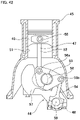
- a variable compression ratio device of the present invention includes: a link mechanism that is connected to a piston of an internal combustion engine and that moves the piston in a vertical direction; a control shaft for changing the posture of the link mechanism by own rotation; and an electric motor for rotating the control shaft; and has a function that, by changing a rotation phase of the control shaft by the electric motor, changes at least one of the top dead center position and the bottom dead center position of the piston to change the engine compression ratio.
- a reverse input shutoff clutch of the present invention is provided between the electric motor and the control shaft; the input member is connected to the electric motor either directly or via a speed reduction mechanism; and the output member is connected to the control shaft or is integrally provided with the control shaft.
- An electric power steering device of the present invention includes: a rotating shaft that rotates based on the operation of a steering wheel and applies a steering angle to steered wheels according to an amount of rotation of the steering wheel; a steering force assisting motor for applying an assisting force to the rotating shaft; and a worm reducer that is provided between the steering force assisting motor and the rotating shaft and that transmits rotation of the steering force assisting motor to the rotating shaft.
- the rotating shaft is configured by connecting an input-side rotating shaft and an output-side rotating shaft coaxially arranged with each other via a reverse input shutoff clutch of the present invention; the input member is connected to the input-side rotating shaft or is integrally provided with the input-side rotating shaft; and the output member is connected to the output-side rotating shaft or is integrally provided with the output-side rotating shaft.
- the axial dimension of the reverse input shutoff clutch may be shortened, and the number of parts may be reduced.
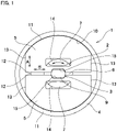
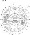
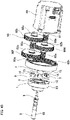
- FIG 1 is a diagram illustrating a reverse input shutoff clutch of a first example of an embodiment of the present invention.
- the axial direction, the radial direction, and the circumferential direction refer to the axial direction, the radial direction, and the circumferential direction of a reverse input shutoff clutch 1.
- the axial direction, the radial direction, and the circumferential direction of the reverse input shutoff clutch 1 coincide with the axial direction, the radial direction, and the circumferential direction of an input member 2, coincide with the axial direction, the radial direction, and the circumferential direction of an output member 3, and coincide with the axial direction, the radial direction, and the circumferential direction of a pressed member 4.
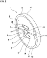
- the reverse input shutoff clutch 1 of this example is a lock-type reverse input shutoff clutch, and includes an input member 2, an output member 3, a pressed member 4, and a pair of engaging elements 5.
- the reverse input shutoff clutch 1 has a reverse input shutoff function that transmits rotational torque that is inputted to the input member 2 to the output member 3, however, completely shuts off rotational torque that is reversely inputted to the output member 3 so as not to be transmitted to the input member 2, or allows only part of that reversely inputted rotational torque to be transmitted to the input member 2 and shuts off the remaining part.
- the input member 2 is connected to an input side mechanism such as an electric motor or the like from which rotational torque is inputted.
- the input member 2 includes an input shaft portion 6 and a pair of input member side engaging portions 7.
- the input shaft portion 6 has a stepped columnar shape, and a base end portion thereof is connected to an output portion of the input side mechanism so as to be able to transmit torque, or is integrally provided with an output portion of the input side mechanism.
- Each of the pair of input member side engaging portions 7 has a substantially elliptical columnar shape, and the pair of input member side engaging portions 7 is constituted by convex portions that extend in the axial direction from two positions on diametrically opposite sides of the tip end surface of the input shaft portion 6.
- Each of the pair of input member side engaging portions 7 is separated from the other in the diameter direction of the input member 2. For this reason, each of the pair of input member side engaging portions 7 is disposed in a portion of the tip end surface of the input shaft portion 6 that is separated outwardly in the radial direction from the center of rotation.
- the input member side engagement portion 7 has an outer side surface in the radial direction thereof that has a contour shape that is the same cylindrical surface shape as the outer circumferential surface of the tip end portion of the input shaft portion 6, and an inner side surface in the radial direction thereof that is an arc-shaped convex surface of which the central portion in the circumferential direction protrudes inward in the radial direction.
- the output member 3 is connected to an output side mechanism such as a speed reduction mechanism or the like, and outputs rotational torque.
- the output member 3 is arranged coaxially with the input member 2 and, as illustrated in FIG 4 , has an output shaft portion 8 and an output member side engaging portion 9.
- the output shaft portion 8 has a columnar shape, and a tip end portion thereof is connected to the input portion of the output side mechanism so as to be able to transmit torque, or is integrally provided with the input portion of the output side mechanism.
- the output member side engaging portion 9 has a cam function. In other words, the distance from the center axis of rotation of the output member 3 to the outer peripheral surface of the output member side engaging portion 9 is not constant in the circumferential direction.
- the output member side engaging portion 9 has a substantially long columnar shape and extends in the axial direction from the central portion of the base end surface of the output shaft portion 8.
- the outer peripheral side surface of the output member side engaging portion 9 is constituted by a pair of flat surfaces that are parallel to each other and a pair of arc-shaped convex surfaces. For this reason, the distance from the center of rotation of the output member side engaging portion 9 to the outer peripheral side surface is not constant in the circumferential direction.
- the output member side engaging portion 9 is arranged in a portion between the pair of input member side engaging portions 7.
- the pressed member 4 is formed in a thin annular shape, and is fixed to another member (not illustrated) such as a housing or the like, for example, and the rotation thereof is restricted.
- the pressed member 4 is arranged coaxially with the input member 2 and the output member 3, and arranged farther on the outer side in the radial direction than the input member 2 and the output member 3. More specifically, the pair of input member side engaging portions 7 and the output member side engaging portion 9 are arranged on the inner side in the radial direction of the pressed member 4 in the assembled state of the reverse input shutoff clutch 1.
- the pressed member 4 has a pressed surface 10, which is a cylindrical surface shaped concave surface, on the inner peripheral surface thereof.
- Each of the pair of engaging elements 5 is formed in a substantially semicircular plate shape, and the pair of engaging elements 5 is arranged on the inner side in the radial direction of the pressed member 4.
- Each of the pair of engaging elements 5 has an outer side surface in the radial direction that is pressed against the pressed surface 10, which constitutes a pressing surface 11 composed of a cylindrical surface shaped convex surface, and an inner side surface in the radial direction, which constitutes a bottom surface 12, other than a portion where an engaging element side output engaging portion 15 (described later) is formed, having a flat surface shape.
- both sides in the width direction of each of the engaging elements 5 are flat surface shaped side surfaces 13 that are perpendicular to the bottom surface 12.
- the radial direction with respect to the engaging element 5 is a direction perpendicular to the bottom surface 12 and is indicated by an arrow A in FIG 1
- a direction parallel to the bottom surface 12 that is indicated by an arrow B in FIG 1 is referred to as the width direction with respect to the engaging element 5.
- the radius of curvature of the pressing surface 11 is equal to or less than the radius of curvature of the pressed surface 10.
- the pressing surface 11 has a surface characteristic of having a large friction coefficient as compared with other portions of the engaging element 5.
- the pressing surface 11 may be configured directly by the surface of the engaging element 5 or may be configured by a friction material fixed to the engaging element 5 by bonding, adhesion or the like.
- the pressing surfaces 11 of the pair of engaging elements 5 are directed to the opposite side in the radial direction of the pressed member 4, and the bottom surfaces 12 of the pair of engaging elements 5 are opposed to each other. Moreover, in a state where the pair of engaging elements 5 is arranged on the inner side in the radial direction of the pressed member 4, the inner diameter dimension of the pressed member 4 and the radial dimensions of the engaging elements 5 are regulated so that there are gaps in at least one of a portion between the pressed surfaces 10 and the pressing surfaces 11 and a portion between the bottom surfaces 12.
- Each engaging element 5 has an engaging element side input engaging portion 14 and an engaging element side output engaging portion 15.
- the engaging element side input engaging portion 14 is configured by a through hole that penetrates an intermediate portion in the radial direction of the engaging element 5 in the axial direction, and is a rectangular long hole that is long in the width direction.
- the engaging element side input engaging portion 14 has a size that allows the input member side engaging portion 7 to be loosely inserted. More specifically, in a state where the input member side engaging portion 7 is inserted inside the engaging element side input engaging portion 14, there are gaps in the width direction and in the direction orthogonal to the width direction of the engaging element 5 between the input member side engaging portion 7 and the inner surface of the engaging element side input engaging portions 14.
- the input member side engaging portion 7 may be displaced in the direction of rotation of the input member 2 with respect to the engaging element side input engaging portion 14 (engaging element 5), and the engaging element side input engaging portion 14 may be displaced in a direction orthogonal to the width direction of the engaging element 5 with respect to the input member side engaging portion 7.
- the engaging element side output engaging portion 15 is constructed by a substantially rectangular concave portion that is recessed outward in the radial direction from the central portion in the width direction of the bottom surface 12 of each of the pair of engagement elements 5.
- Each engaging element side output engaging portion 15 has a size and a shape such that a front half part in the minor axis direction of the output member side engaging portion 9 may be disposed on the inner side thereof without looseness. More specifically, the opening width of the engaging element side output engaging portion 15 is substantially the same (the same or slightly larger) as the dimension in the major axis direction of the output member side engaging portion 9, and the depth in the radial direction is slightly smaller than 1/2 of the dimension in the minor axis direction of the output member side engaging portion 9.
- the bottom portion of the engaging element side output engaging portion 15 is a flat surface parallel to the bottom surface 12.
- the pair of input member side engaging portions 7 of the input member 2 arranged on one side in the axial direction is respectively inserted in the axial direction into each of the engaging element side input engaging portion 14 of the pair of engaging elements 5, and the output member side engaging portion 9 of the output member 3 arranged on the other side in the axial direction is inserted in the axial direction into between the pair of engaging element side output engaging portions 15.
- the pair of engaging elements 5 is arranged so that the output member side engaging portion 9 is sandwiched from the outer side in the radial direction by the engaging element side output engaging portions 15.
- the dimension in the axial direction of the input member side engaging portions 7, the dimension in the axial direction of the output member side engaging portion 9, the dimension in the axial direction of the pressed member 4, and the dimensions in the axial direction of the engaging elements 5 are mostly the same.
- the pair of engaging elements 5 is moved inward in the radial direction, that is to say, in a mutually approaching direction (the engaging element 5 located on the upper side in FIG 5 is moved downward, and the engaging element 5 located on the lower side in FIG 5 is moved upward).
- the bottom surfaces 12 of the pair of engaging elements 5 move in a direction toward each other, and the pair of engaging element side output engaging portions 15 sandwich the output member side engaging portion 9 of the output member 3 from both sides in the radial direction.
- the output member side engaging portion 9 is made to engage with the pair of engaging element side output engaging portions 15 without looseness. Therefore, the rotational torque that is inputted to the input member 2 is transmitted to the output member 3 via the pair of engaging elements 5 and outputted from the output member 3.
- the reverse input shutoff clutch 1 of this example moves the pair of engaging elements 5 in directions away from the pressed surface 10, regardless of the direction of rotation of the input member 2. Then, regardless of the direction of rotation of the input member 2, the rotational torque inputted to the input member 2 is transmitted to the output member 3 via the pair of engaging elements 5.
- the pair of engaging elements 5 are moved outward in the radial direction, that is to say, in a mutually separating direction (the engaging element 5 located on the upper side in FIG 5 is moved upward, and the engaging element 5 located on the lower side in FIG 5 is moved downward).
- each pressing surface 11 of the pair of engaging elements 5 is pressed against the pressed surface 10 of the pressed member 4.
- the pressing surfaces 11 and the pressed surface 10 are in contact with each other over the entire range or a part of the range (for example, the central portion) of the pressing surfaces 11 in the circumferential direction.
- the pair of engaging elements 5 is stretched between the output member side engaging portion 9 and the pressed member 4 to lock the output member 3 so that the pressing surfaces 11 do not slide (relatively rotate) with respect to the pressed surface 10.
- the pair of engaging elements 5 is stretched between the output member side engaging portion 9 and the pressed member 4 to semi-lock the output member 3 so that the pressing surfaces 11 slide with respect to the pressed surface 10.
- the pair of engaging elements 5 rotate about the center of rotation of the output member 3 while the pressing surfaces 11 slide with respect to the pressed surfaces 10 due to the engagement between the output member side engaging portion 9 and the engaging element side output engaging portions 15.
- the inner surfaces of the engaging element side input engaging portions 14 press the inner side surfaces in the radial direction of the input member side engaging portions 7 in the circumferential direction (direction of rotation), and part of the rotational torque is transmitted to the input member 2.
- the input member side engaging portion 7 does not prevent the engaging element 5 from moving to the outer side in the radial direction (upper side in FIG 9 ), and even after the pressing surface 11 comes in contact with the pressed surface 10, the surface pressure acting on the contact portion between the pressing surface 11 and the pressed surface 10 changes according to the magnitude of the rotational torque reversely inputted to the output member 3 thereby properly locking or semi-locking the output member 3.
- the normal force Fc is expressed by the following equation (2) using the tangential force Ft.
- Fc Ft / sin ⁇ + ⁇ ⁇ cos ⁇
- the friction coefficient ⁇ ',the distance R, and the normal force Fc may be increased in order to obtain a larger braking force.
- the output member 3 may be locked by appropriately setting the distance r from the rotation center O of the output member 3 to the contact portion X, the distance R from the center of rotation O of the output member 3 to the contact portion Y, and the wedge angle ⁇ between the direction of the line of action of the tangential force Ft and the bottom surface of the engaging element side output engaging portion 15.
- the output member 3 may be semi-locked by appropriately setting the friction coefficient ⁇ between the output member side engaging portion 9 and the engaging element side output engaging portion 15, the friction coefficient ⁇ ' between the pressing surface 11 and the pressed surface 10, the distance r from the rotation center O to the contact portion X, the distance R from the center of rotation O to the contact portion Y, and the wedge angle ⁇ between the direction of the line of action of the tangential force Ft and the bottom surface of the engaging element side output engaging portion 15.
- the locked or semi-locked state of the output member 3 is released when the normal force acting on the engaging element 5 from the input member 2 becomes larger than the normal force Fc acting on the engaging element 5 from the output member 3.
- the engaging element 5 moves inward in the radial direction, and rotational torque is transmitted from the input member 2 to the output member 3.
- the dimension in the axial direction may be shortened and the number of parts may be reduced.
- the reverse input shutoff clutch 1 of this example converts the rotation of the input member 2 and the output member 3 into movement of the engaging element 5 in the radial direction. Then, by converting the rotation of the input member 2 and the output member 3 into movement of the engaging element 5 in the radial direction in this way, the engaging element 5 is made to engage with the output member 3 located on the inner side of the engaging element 5 in the radial direction, or the engaging element 5 is pressed against the pressed member 4 located on the outer side of the engaging element 5 in the radial direction.
- the reverse input shutoff clutch 1 of this example due to the movement of the engaging element 5 in the radial direction that is controlled by the respective rotation of the input member 2 and the output member 3, it is possible to switch between a state in which the locked or semi-unlocked state of the output member 3 is released so that rotational torque may be transmitted from the input member 2 to the output member 3, and the locked or semi-locked state of the output member 3 so that the rotation of the output member 3 is prevented or suppressed, so the overall dimension of the reverse input shutoff clutch 1 in the axial direction may be shortened.
- the engaging element 5 has both a function of transmitting rotational torque that is inputted to the input member 2 to the output member 3, and a function of locking or semi-locking the output member 3. Accordingly, the number of parts of the reverse input shutoff clutch 1 may be reduced, and the operation may be stabilized as compared with a case where the function of transmitting rotational torque and the function of locking or semi-locking are provided in different members. For example, in a case where a function of transmitting rotational torque and a function of locking or semi-locking are provided in separate members, there is a possibility that the timing for releasing the lock or semi-lock and the timing for starting transmission of rotational torque may be different.
- the engaging element 5 is provided with both the function of transmitting rotational torque to the output member 3 and the function of locking or semi-locking the output member 3, so it is possible to prevent the occurrence of such a problem.
- the direction of the force acting on the engaging element 5 from the input member 2 and the direction of the force acting on the engaging element 5 from the output member 3 are opposite, so by restricting the magnitude relationship between the two forces, the movement direction of the engaging element 5 may be controlled. Therefore, the switching operation for switching the output member 3 between a locked or semi-locked state and a state in which the lock or semi-lock is released may be performed stably and reliably. Therefore, as in a reverse input shutoff clutch having a conventional structure as described in JP 2007-232095A and JP 2004-084918A , it is possible to prevent a problem of the locked state not being released because of a remaining rolling body biting into the narrow portion in the radial direction of the wedge-shaped space.
- each of a pair of input member side engaging portions 7a of an input member 2a has inner surface in the radial direction that is a flat surface parallel to that of the other of the pair.
- the configurations and operational effects of the other parts are the same as those of the first example.
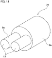
- each of the pair of input member side engaging portions 7b of the input member 2b is constituted by a pair of pin portions 16. More specifically, the pair of input member side engaging portions 7b is arranged at two locations on opposite sides in the radial direction of the tip end surface of the input shaft portion 6a, and respectively configured by pin portions 16 that are arranged at two positions spaced apart from each other, and a pair of pin portions 16 adjacent to each other constitutes each of the pair of input member side engaging portions 7b. In other words, the pair of pin portions 16 of the input member side engaging portions 7b is loosely inserted inside the engaging element side input engaging portion 14 of the engaging element 5. Note that in this example, each pin portion 16 is configured by supporting and fixing a pin formed separately from the input shaft portion 6a into a circular hole formed in the tip end surface of the input shaft portion 6a by press fitting or the like.
- the output member side engaging portion 9a of the output member 3a is constituted by a pair of pin portions 17.
- the pair of pin portions 17 are arranged on both sides of the tip end surface of the output shaft portion 8a with the center axis of rotation of the output member 3a interposed therebetween. Therefore, the distance from the center axis of rotation of the output member 3a to the outer peripheral surface of the output member side engaging portion 9a including the pair of pin portions 17 is not constant in the circumferential direction.
- each pin portion 17 is configured by supporting and fixing a pin formed separately from the output shaft portion 8a into a circular hole formed in the tip end surface of the output shaft portion 8a by press fitting or the like.
- the looseness in the direction of rotation of the engaging element 5 with respect to the input member 2b and the looseness of the engaging element 5 with respect to the output member 3a may be adjusted to an appropriate magnitude.
- the configurations and operational effects of the other parts are the same as those of the first example.
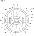
- a fourth example of an embodiment of the present invention will be described with reference to FIG 14 .
- a feature of the reverse input shutoff clutch 1b of this example is that the posture of each of the pair of engaging elements 5a is stabilized, and the engaging elements 5a are accurately moved in the radial direction.
- guide slits 18 that extend in the vertical direction from each bottom surface 12a are provided on both sides in the width direction sandwiching the engaging element side output engaging portion 15 of the bottom surfaces 12a of the engagement elements 5a.
- a cylindrical or rectangular columnar guide 19 is arranged in a pair of guide slits 18 existing on the same straight line so as to span between the pair of guide slits 18.
- the guide 19 is arranged so as to be able to move in the axial direction of the guide 19 without looseness inside the guide slits 18.
- the pair of engaging elements 5a may be moved in the radial direction and rotated in synchronization, however, are prevented from rotating relative to each other or moving in the width direction. Accordingly, the posture of each of the pair of engaging elements 5a may be stabilized. Moreover, the pair of engaging elements 5a may be moved in the radial direction accurately and smoothly. Therefore, the force acting on the engaging element 5a from the input member side engaging portion 7 or the output member side engaging portion 9 may be efficiently used for movement of the engaging element 5a in the radial direction, and the desired transmission torque and braking torque may be generated.
- the other configurations and operational effects are the same as those of the first example.
- a fifth example of an embodiment of the present invention will be described with reference to FIG 15 and FIG 16 .
- a feature of the reverse input shutoff clutch 1c of this example is also to stabilize the respective postures of the pair of engaging elements 5, and precisely move the engaging elements 5 in the radial direction.
- both sides in the width direction of the inner ends in the radial direction of the pair of engaging elements 5 are respectively guided by a guide 19a having a substantially U-shaped cross section.
- the pair of engaging elements 5 may be prevented from rotating relative to each other or moving in the width direction while being able to move in the radial direction and rotate in synchronization.
- a feature of the reverse input shutoff clutch 1d of this example is also to stabilize the respective postures of the pair of engaging elements 5b, 5c, and precisely move the engaging elements 5b, 5c in the radial direction.
- a pair of overhang portions 20 are provided on both side portions of the bottom surface 12b in the width direction of one engaging element 5b (upper engaging element 5b in FIG 17 ) and extend toward the other engaging element 5c (lower engaging element 5c in FIG 17 ).
- notches 21 are provided on both side portions of the bottom surface 12c in the width direction of the other engaging element 5c. Accordingly, the width dimension of inner end portion in the radial direction of the other engaging element 5c is made smaller by the amount of the pair of notches 21. Then, in a state where the pair of engaging elements 5b, 5c is arranged on the inner side of the pressed member 4 in the radial direction, the inner end portion in the radial direction of the other engaging element 5c is arranged between the pair of overhang portions 20 with no looseness. In order for this, the width dimension between the inner side surfaces of the pair of overhang portions 20 is slightly larger than the width dimension of the inner end portion in the radial direction of the other engaging element 5c.
- a seventh example of an embodiment of the present invention will be described with reference to FIG 18 and FIG 19 .
- a feature of the reverse input shutoff clutch 1e of this example is preventing looseness of an output member 3b.
- an auxiliary shaft portion 22 is provided so as to pass through an output member side engaging portion 9b in the major axis direction, and both side portions in the axial direction of the auxiliary shaft portion 22 are exposed to the outside of the output member side engaging portion 9b.
- both side portions in the axial direction of the auxiliary shaft portion 22 are arranged between bottom surfaces 12d of a pair of engaging elements 5d.
- concave housing portions 23 are provided in portions in the width direction of the bottom surfaces 12d of the engaging elements 5d so as to face the one side portion in the axial direction and the other side portion in the axial direction of the auxiliary shaft portion 22, and extend vertically from the bottom surfaces 12d. More specifically, a concave housing portion 23 is provided on the upper engaging element 5c in FIG 18 in a portion of the bottom surface 12d that is farther on the left side than the engaging element side output engaging portion 15, and a concave housing portion 23 is provided on the lower engaging element 5c in FIG 18 in a portion of the bottom surface 12d that is farther on the right side than the engaging element side output engaging portion 15.
- An elastic member 24 is arranged inside each concave housing portion 23, and these elastic members 24 are elastically compressed between the bottom portions of the concave housing portions 23 and the one side in the axial direction and the other side in the axial direction of the auxiliary shaft portion 22. Accordingly, a moment in a specified direction (counterclockwise in the example in FIG 18 ) is applied to the output member 3b via the auxiliary shaft portion 22. Moreover, the one side in the axial direction and the other side in the axial direction of the auxiliary shaft portion 22 are pressed against the bottom surfaces 12d of the engaging elements 5d.
- a moment may be applied to the output member 3b, so even in a state where no load is applied to the output member 3b, it is possible to prevent the output member 3b from being loose with respect to the engaging elements 5d.
- the other configurations and operational effects are the same as those of the first example.
- the shape of the outer surfaces in the radial direction of the pair of engaging elements 5e is devised, and a wedge effect is used to obtain a larger normal force (braking torque).
- pressing surfaces 11a that press against the pressed surface 10 are provided at two positions spaced apart in the circumferential direction on the outer side surface in the radial direction of each engaging element 5e.
- Each pressing surface 11a is a cylindrical convex surface having a radius of curvature Cr' that is smaller than the radius of curvature Cr of the pressed surface 10.
- a flat surface-shaped tip end surface 25 is provided so as not to be pressed against the pressed surface 10 (a gap is always present between the tip end surface 25 and the pressed surfaces 10).
- the width dimension in the radial direction of the engaging element 5e is smaller than that of the engaging element 5 of the first example.
- the contour shape of the outer side surface in the radial direction of the engaging element 5 of the first example is generally arc shaped, whereas the contour shape of the outer side surface in the radial direction of the engaging element 5e of the present example is configured by connecting the end portions of a pair of arc portions with straight line portions.
- an engaging element side input engaging portion 14a that is a substantially arc-shaped long hole is provided in an intermediate portion in the radial direction of each engaging element 5e. Then, inside the engaging element side input engaging portion 14a, the input member side engaging portions 7 of the input member 2 may be moved toward or away from the pressed surface 10 and be loosely engaged so as to be able to move in the direction of rotation of the input member 2. Moreover, both side surfaces in the width direction of the engaging elements 5e are made into inclined surfaces 26 such that the angle formed with the bottom surface 12e is an obtuse angle.
- the magnitude of the braking torque T' is expressed by the following equation (12) using the friction coefficient ⁇ ', the distance R (clutch size), the normal force Fc, and the wedge angle ⁇ .
- T ′ ⁇ ′ RFc / sin ⁇ + ⁇ ′ ⁇ cos ⁇
- the friction coefficient ⁇ ' is 0.1
- the distance R is 15 mm
- the wedge angle ⁇ is 25 degrees
- the normal force Fc is 1000 N.
- the braking torque T' obtained by the reverse input shutoff clutch 1 of the first example is 1.5 Nm
- the braking torque T' obtained by the reverse input shutoff clutch 1f of the present example becomes 2.9 Nm.
- a braking torque T' that is approximately twice as large compared to that of the reverse input shutoff clutch 1 of the first example may be obtained.
- a braking torque T' having a magnitude that is the same as that in the case of the reverse input shutoff clutch 1 of the first example, may be obtained even when the distance R is halved.
- a larger braking torque T' may be obtained compared to that of the reverse input shutoff clutch 1 of the first example even in the case of using an equivalent friction coefficient ⁇ ', an equivalent distance R, and an equivalent transmission torque T. Therefore, in order to obtain the required rotational torque shutoff rate, the distance R may be easily reduced even without increasing the friction coefficient ⁇ ' and the normal force Fc. Such an effect is acquired by just devising the shape of the outer side surface in the radial direction of the engaging element 5c, so an increase in cost may also be suppressed.
- the other configurations and operational effects are the same as those of the first example.
- a ninth example of an embodiment will be described with reference to FIG 21 .
- the shape of a bottom surface 12f which is the inner side surface in the radial direction of an engaging element 5f is devised.
- the entire inner side surface in the radial direction of the engaging element 5f is a flat bottom surface 12f
- an engaging element side output engaging portion 15a is constituted by the center portion in the width direction of the bottom surface 12f.
- the engaging element side output engaging portion 15 (refer to FIG 1 and the like) that is recessed outward in the radial direction from the bottom surface 12 is not provided as in the engaging element 5 of the first example.
- the bottom surface 12f of the engaging element 5f At least the part constituting the engaging element side output engaging portion 15a is a portion in contact with the output member side engaging portion 9 of the output member 3, so it is necessary to perform high-precision finishing.
- the entire bottom surface 12f, including the engaging element side output engaging portion 15a is formed into a flat surface shape, and since the engaging element side output engaging portion 15 is not provided so as to be recessed outward in the radial direction from the bottom surface 12 as in the first example, it is possible to perform high-precision finishing at low cost by using machine tools such as a surface grinder or the like.
- the other configurations and operational effects are the same as those of the first example.
- a tenth example of an embodiment of the present invention will be described with reference to FIG 22 and FIG 23 .
- a feature of the reverse input shutoff clutch 1h of this example is that the posture of each of the pair of engaging elements 5g is stabilized, and the engaging elements 5g are accurately moved in the radial direction.
- cylindrical concave guide portions 27 that are recessed in the direction perpendicular to the bottom surface 12g are provided on both side portions in the width direction of the bottom surface 12g of the engaging element 5g.
- an elastic member 24a which is a coiled spring, is arranged inside each of the pairs of concave guide portions 27 existing on the same straight line so as to span between each of the pairs of concave guide portions 27.
- the pair of engaging elements 5g is pressed toward the pressed surface 10 by using the elastic force exerted by the pair of elastic members 24a.
- the magnitude of the elastic force (magnitude of the spring load) exerted by the elastic members 24a is set larger than the weight of each of the engaging elements 5g in order to prevent an engaging element 5g from moving downward due to the influence of gravity.
- the movement in the radial direction of the pair of engaging elements 5g may be accurately performed by synchronizing and stabilizing the postures of the pair of engaging elements 5g.
- the configuration is simple such that a pair of elastic members 24a is provided so as to span the pairs of engaging elements 5g, it is possible to effectively prevent an engaging element 5g from moving downward due to the influence of gravity and prevent the postures from becoming unstable.
- the other configurations and operational effects are the same as those of the first example and ninth example.
- each of the pair of engaging elements 5h includes an engaging element side input engaging portion 14b that is a concave portion recessed inward in the radial direction at the center in the circumferential direction of the outer side surface in the radial direction.
- the input member side engaging portions 7 of the input member 2a are loosely engaged inside the engaging element side input engaging portions 14b.
- each of the pair of engaging elements 5h has a portion that is arranged on the inner side in the radial direction of the input member side engaging portion 7, and portions that are arranged on both sides in the circumferential direction of the input member side engaging portion 7, however, does not have a portion arranged on the outer side in the radial direction of the input member side engaging part 7. Accordingly, the reverse input shutoff clutch 1i may be reduced in weight.
- the output member side engaging portion 9c of the output member 3c has a substantially rectangular column shape. More specifically, the outer peripheral surface of the output member side engaging portion 9c includes a pair of first flat surfaces parallel to each other in the long-side direction, a pair of second flat surfaces parallel to each other in the short-side direction, and partial cylindrical surfaces connecting the first flat surfaces and the second flat surfaces.
- the other configurations and operational effects are the same as those of the first example, eighth example, and ninth example.
- FIG 26A to FIG 26D A twelfth example of an embodiment of the present invention will be described with reference to FIG 26A to FIG 26D .
- four examples of cross-sectional shapes that may be employed respectively for the pressed surface 10 provided on the inner peripheral surface of the pressed member 4 and the pressing surface 11 provided on the outer side surface of the engaging element 5 in the radial direction will be described.
- the cross-sectional shapes of both the pressed surface 10 and the pressing surface 11 are both linear.
- Such a structure has an advantage in that the processing cost may be kept low because the pressed surface 10 and the pressing surface 11 can be easily processed.
- an edge load tends to be generated between the corners present at both ends in the aixal direction of the pressing surface 11 and the pressed surface 10. Accordingly, wear tends to proceed and durability tends to be low.
- both the pressed surface 10 and the pressing surface 11 are both linear.
- planar (partially conical surface) chamfered portions 28 are provided on both sides in the axial direction of the pressing surface 11 positioned at both end portions in the axial direction of the outer side surface in the radial direction of the engaging element 5.
- the cross-sectional shapes of both the pressed surface 10 and the pressing surface 11 are both linear.
- convex curved chamfered portions 28a are provided on both sides in the axial direction of the pressing surface 11 positioned at both end portions in the axial direction of the outer side surface in the radial direction of the engaging element 5.
- the cross-sectional shapes of both the pressed surface 10 and pressing surface 11 are circular arc shape. More specifically, the cross-sectional shape of the pressed surface 10 is a concave arc shape, and the cross-sectional shape of the pressing surface 11 is a convex arc shape. Moreover, the radius of curvature of the cross-sectional shape of the pressing surface 11 is made smaller than the radius of curvature of the cross-sectional shape of the pressed surface 10. With such a configuration, it is possible to increase the inclination angle of the engaging element 5 compared to the case of the third example described above without the occurrence of edge loading. However, compared to the third example, the processing of the pressed surface 10 and the pressing surface 11 is troublesome, and the processing cost is likely to increase.
- a thirteenth example of an embodiment of the present invention will be described with reference to FIG 27 .
- a feature of the reverse input shutoff clutch 1j of this example is that the shutoff rate differs depending on the direction of the rotational torque reversely inputted to an output member 3d.
- the shutoff rate may be calculated by following equation (13).
- Shutoff rate of rotational torque reversely inputted to output member 3d Rotational torque reversely inputted to output member 3d ⁇ Rotational torque transmitted to input member 2 / Rotational torque reversely inputted to output member 3d
- the cross-sectional shape of the output member side engaging portion 9d of the output member 3d is a substantially a parallelogram.
- the pair of engaging elements 5i is arranged so that the engaging element side output engaging portions 15 sandwich the output member side engaging portion 9d from both sides in the radial direction.
- the distance r from the center of rotation O of the output member 3d to the contact portion between the corners of the output member side engaging portion 9d and the bottom portion of the engaging element side output engaging portions 15 becomes larger in a case where the output member 3d rotates in the clockwise direction than in a case where the output member 3d rotates in the counterclockwise direction. Therefore, presuming that the magnitude of rotational torque reversely inputted to the output member 3d is the same regardless of the direction of rotation of the output member 3d, the magnitude of the braking torque T' acting on the engaging elements 5i becomes smaller in a case where the output member 3d rotates in the clockwise direction than in a case where the output member 3d rotates in the counterclockwise direction.
- the shutoff rate of the reverse input shutoff clutch 1j becomes smaller in a case where the output member 3d rotates in the clockwise direction than in a case where the output member 3d rotates in the counterclockwise direction. Note that when the output member 3d rotates in the counterclockwise direction, rotational torque reversely inputted to the output member 3d may be completely shut off so as not to be transmitted to the input member 2, or it is possible to shut off part and transmit the remaining part to the input member 2.
- each of the engaging elements 5i has a pressing surface 11a that is pressed against the pressed surface 10 at two positions of the outer side surface in the radial direction separated from each other in the circumferential direction, and has a tip end surface 25 that is provided at an intermediate portion in the circumferential direction that is a portion of the outer side surface in the radial direction between the pair of pressing surfaces 11a.
- the configurations and operational effects of the other portions are the same as those of the first example and eighth example.
- a fourteenth example of an embodiment of the present invention will be described with reference to FIG 28 .
- a feature of the reverse input shutoff clutch 1k of this example, as in the reverse input shutoff clutch 1j of the thirteenth example, is that the shutoff rate differs depending on the direction of rotational torque reversely inputted to an output member 3e.
- the cross-sectional shape of an output member side engaging portion 9e of the output member 3e is substantially a parallelogram.
- a pair of engaging elements 5j is arranged so that engaging element side output engaging portions 15 sandwich the output member side engaging portion 9e from both sides in the radial direction.
- the reverse input shutoff clutch 1k of this example has a feature in that the posture of the pair of engaging elements 5j is stabilized and the displacement in the radial direction of the engaging elements 5j is accurately performed.
- each engaging element 5j is provided with cylindrical concave guide portions 27 on both side portions in the width direction of a bottom surface 12g so as to be recessed in a direction perpendicular to the bottom surface 12g.
- an elastic member 24a is arranged inside each of pairs of concave guide portions 27 on the same straight line so that in a state in which the bottom surfaces 12g of the pair of engaging elements 5g oppose each other, the elastic member 24a spans between the pair of concave guide portions 27.
- each engaging element 5j has a guide hole 29 that is formed in the radial direction of the engaging element 5j, and opens to the bottom portion of the engaging element side output engaging portion 15 and the inner surface of the engaging element side input engaging portion 14.
- the output member 3e has an insertion through hole 30 that penetrates through the output member side engaging portion 9e. Then, both end portions in the axial direction of a guide 19b having a columnar shape are inserted into each guide hole 29 of the pair of engaging elements 5j so that there is no looseness in the radial direction and so as to be able to move in the axial direction, and an intermediate portion in the axial direction of the guide 19b is loosely inserted into the insertion through hole 30 of the output member side engaging portion 9e.
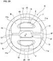
- a fifteenth example of an embodiment of the present invention will be described with reference to FIG 29 .
- a feature of the reverse input shutoff clutch 11 of this example, as in the reverse input shutoff clutch 1j of the thirteenth example, is that the shutoff rate differs depending on the direction of rotational torque reversely inputted to an output member 3f.
- the output member 3f is asymmetric with respect to a virtual plane parallel to the axial direction of the output member 3f and the direction of movement of the pressing surface 11a toward or away from the pressed surface 10 (the radial direction of the engaging element 5i), and has an output member side engaging portion 9f having a substantially trapezoidal cross-sectional shape.
- the pair of engaging elements 5i is arranged so that the engaging element side output engaging portions 15 sandwich the output member side engaging portion 9f from both sides in the radial direction.
- the distance r from the center of rotation O of the output member 3f to the contact portion between the corner portions of the output member side engaging portion 9f and the bottom portion of the engaging element side output engaging portion 15 becomes smaller in a case where the output member 3f rotates in the clockwise direction than in a case where the output member 3f rotates in the counterclockwise direction.
- the magnitude of the braking torque T' acting on the one engaging elements 5i becomes larger in a case where the output member 3f rotates in the clockwise direction than in a case where the output member 3f rotates in the counterclockwise direction.
- the distance r is the same regardless of the direction of rotation of the output member 3f, and the magnitude of the braking torque T' acting on the other engaging element 5i is also the same.
- the shutoff rate of the entire reverse input shutoff clutch 11 becomes larger in a case where the output member 3f rotates in the clockwise direction than in a case where the output member 3f rotates in the counterclockwise direction.
- the configurations and operational effects of the other portions are the same as those of the first example, eighth example, and thirteenth example.
- a sixteenth example of an embodiment of the present invention will be described with reference to FIG 30 .
- a feature of the reverse input shutoff clutch 1m of this example, as in the reverse input shutoff clutch 1j of the thirteenth example, is that the shutoff rate differs depending on the direction of rotational torque reversely inputted to an output member 3d.
- the cross-sectional shape of the output member side engaging portion 9d of the output member 3d is substantially a parallelogram.
- the pair of engaging elements 5i is arranged so that the engaging element side output engaging portions 15 sandwich the output member side engaging portion 9d from both sides in the radial direction.
- the magnitude of looseness of the input member side engaging portion 7c with respect to the engaging element side input engaging portion 14 of the engaging element 5i varies depending on the direction of rotation of the input member 2c. More specifically, each input member side engaging portions 7c has an asymmetric shape with respect to the rotation direction of the input member 2c. In the illustrated example, the looseness of the input member side engaging portions 7c with respect to the engaging element side input engaging portions 14 becomes larger in a case where the input member 2c rotates in the clockwise direction than in a case where the input member 2c rotates in the counterclockwise direction.
- the rotational torque that is required to release the lock or semi lock state may be made smaller in a case where the input member 2c rotates in the clockwise direction than in a case where the input member 2c rotates in the counterclockwise direction.
- the configurations and operational effects of the other portions are the same as those of the first example and thirteenth example.
- a seventeenth example of an embodiment of the present invention will be described with reference to FIG 31 .
- a feature of the reverse input shutoff clutch In of this example is that the shutoff rate differs depending on the direction of rotational torque reversely inputted to an output member 3g.
- the output member 3g includes an output member side engaging portion 9g having a substantially rectangular cross section, and the center axis of the output member side engaging portion 9g is offset in the radial direction with respect to the center of rotation O of the output member 3g.
- the reverse input shutoff clutch In of this example includes only one engaging element 5 having an engaging element side output engaging portion 15 that engages with the output member side engaging portion 9g.
- the input member 2d of the reverse input shutoff clutch In of this example includes only one input member side engaging portion 7.
- the distance r from the center of rotation O of the output member 3g to the contact portion between the corner portions of the output member side engaging portion 9g and the bottom portion of the engaging element side output engaging portion 15 becomes larger in a case where the output member 3g rotates in the clockwise direction than in a case where the output member 3g rotates in the counterclockwise direction. Accordingly, presuming that the magnitude of the rotational torque reversely inputted to the output member 3g is the same regardless of the direction of rotation of the output member 3g, the magnitude of the braking torque T' acting on the engaging element 5 becomes smaller in a case where the output member 3g rotates in the clockwise direction than in a case where the output member 3g rotates in the counterclockwise direction. In short, the shutoff rate of the reverse input shutoff clutch In becomes smaller in a case where the output member 3g rotates in the clockwise direction than in a case where the output member 3d rotates in the counterclockwise direction.
- the feature that the shutoff rate differs depending on the direction of rotational torque reversely inputted to the output member 3g is achieved by a structure that includes only one engaging element 5. Therefore, compared with the reverse input shutoff clutch 1j of the thirteenth example, the number of parts may be reduced.
- the configurations and operational effects of the other portions are the same as those of the first example and thirteenth example.
- FIG 32 to FIG 40 An eighteenth example of an embodiment of the present invention will be described with reference to FIG 32 to FIG 40 .
- a feature of this example is that the reverse input shutoff clutch of the present invention is applied to an electric valve timing adjustment device.
- the electric valve timing adjustment device described in JP 2010-255494A has a speed reduction mechanism such as a differential gear mechanism between a driven member such as a sprocket or the like that is rotationally driven by a crankshaft and a camshaft.
- the phase difference between the camshaft and the crankshaft is changed by changing the engaging position of the speed reduction mechanism by an electric motor.
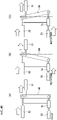
- the rotational speed of an electric motor 33 is set so as to be equal to the rotational speed of the sprocket 32.
- the rotational speed of the electric motor 33 is set so as to be slower than the rotational speed of the sprocket 32.
- the rotational speed of the electric motor 33 is set so as to be faster than the rotational speed of the sprocket 32.
- the length of the white arrow indicates the magnitude of the rotational speed
- the direction of the white arrow indicates the direction of rotation.
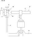
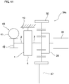
- the electric valve timing adjustment device 34 of this example is incorporated in an internal combustion engine 35.
- the internal combustion engine 35 has a crankshaft 36, and camshaft 31 that drives at least one of an intake valve and an exhaust valve.
- an interlocking mechanism 37 such as a chain, a belt or the like, and the electric valve timing adjustment device 34 are provided between the camshaft 31 and the crankshaft 36.
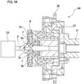
- the electric valve timing adjustment device 34 includes an electric motor 33, a sprocket 32 as a driven member, a speed reduction mechanism 38, and a reverse input shutoff clutch 1o.
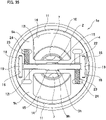
- the reverse input shutoff clutch 1o includes an input member 2, an output member 3h, a pressed member 4, and a pair of engaging elements 5k.
- the electric motor 33 is controlled by an electronic control unit (ECU) (not illustrated) so as to have an optimal valve timing, and is connected to the input member 2 constituting the reverse input shutoff clutch 1o so as to transmit torque.
- ECU electronice control unit
- Output signals from a plurality of sensors such as a rotation angle sensor of the camshaft 31, a rotation angle sensor of the crankshaft 36, a rotational speed sensor of the electric motor 33 and the like are inputted to the electronic control unit.
- the electronic control unit controls the rotational speed (actual phase difference) of the electric motor 33 so as to approach a target rotational speed (target phase difference) that is set based on the output signals of the plurality of sensors.
- the sprocket 32 is rotationally driven by the crankshaft 36 via the interlocking mechanism 37. Moreover, in a case, for example, where the internal combustion engine 35 is a four-stroke engine, the sprocket 32 rotates in synchronization at 1/2 of the rotational speed of the crankshaft 36.
- the sprocket 32 is externally fitted and fixed to the pressed member 4 of the reverse input shutoff clutch 1o. Accordingly, the pressed member 4 rotates as the crankshaft 36 rotates.
- the speed reduction mechanism 38 is a differential gear mechanism such as a planetary gear mechanism or the like, and has a first input portion, a second input portion, and an output portion, and the phase difference between the camshaft 31 and the crankshaft 36 is changed by moving the engagement position between the camshaft 31 and the crankshaft 36 to the advance angle side or the delay angle side.
- a planetary gear mechanism such as a planetary gear mechanism or the like
- a configuration may be adopted in which the output member 3h of the reverse input shutoff clutch 1o is connected to a sun gear that is the first input portion, the sprocket 32 is connected to the ring gear that is the second input portion, and the camshaft 31 is connected to the planetary carrier that is the output portion.
- the sun gear connected to the output member 3h is rotated relative to the ring gear connected to the sprocket 32, whereby it is possible to change the phase difference between the camshaft 31 connected to the planetary carrier and the crankshaft 36.
- the basic structure of the reverse input shutoff clutch 1o of the present example is the same as that of the reverse input shutoff clutch 1 of the first example of an embodiment of the present invention described above; however, as illustrated in FIG 35 and FIG 36 , as in the structure of the fourth example, guides 19 are arranged so as to span guide slits 18 provided on both sides in the width direction of the bottom surfaces 12i of the pair of engaging elements 5k. This ensures an accurate movement in the radial direction of the pair of engaging elements 5k.
- the reverse input shutoff clutch 1o of the present example has a similar structure to that of the seventh example in that elastic members 24 are arranged in concave housing portions 23 provided in the engaging elements 5k, thereby allowing a moment in a specified direction (counterclockwise in FIG 35 and FIG 36 ) to be applied to the output member 3h via an auxiliary shaft portion 22 that is inserted through the output member side engaging portion 9h. This prevents the output member 3h from being loose with respect to the engaging elements 5k.
- the reverse input shutoff clutch 1o utilizes the rotation of the output member side engaging portion 9h functioning as a cam, and by pressing the engaging element side output engaging portions 15 of the engaging elements 5k, the engaging elements 5k are moved outward in the radial direction, so as illustrated in FIG 37 , gaps 39 are required between the outer peripheral side surface of the output member side engaging portion 9h and the bottom surfaces of the engaging element side output engaging portions 15.
- the output member 3h is rotationally driven by the electric motor 33 or the sprocket 32, so the direction of torque inputted to the output member 3h varies positively and negatively as illustrated in FIG 38 .
- the reverse input shutoff clutch 1o of the present example has a configuration in which, when the normal force Fa acting on the engaging elements 5k from the input member 2 becomes larger than the normal force Fc acting on the engaging elements 5k from the output member 3, the engaging elements 5k move inward in the radial direction, and rotational torque is transmitted from the input member 2 to the output member 3h.
- the electric motor 33 In order to cause a phase difference between the camshaft 31 and the sprocket 32, the electric motor 33 is driven, and the electric motor 33 inputs a rotational torque to the input member 2 in the same direction of rotation as the sprocket 32.
- the input member side engaging portions 7 are rotated inside the engaging element side input engaging portions 14 in the direction of rotation of the input member 2 (counterclockwise direction in the example in FIG 35 ). Then, the inner side surface in the radial direction of the input member side engaging portions 7 press the inner surfaces of the engaging element side input engaging portions 14 inward in the radial direction, and each of the pair of engaging elements 5 moves in a direction away from the pressed surface 10.
- each of the pair of engaging elements 5k is moved inward in the radial direction, which is a direction away from the pressed surface 10 (the engaging element 5k located on the upper side in FIG 35 is moved downward, and the engaging element 5k located on the lower side in FIG 35 is moved upward).
- the bottom surfaces 12 of the pair of engaging elements 5k move in a direction toward each other, and the pair of engaging element side output engaging portions 15 sandwich the output member side engaging portion 9h of the output member 3h from both sides in the radial direction.
- the output member side engaging portion 9 is made to engage with the pair of engaging element side output engaging portions 15 without looseness. Therefore, the rotational torque inputted to the input member 2 from the electric motor 33 is transmitted to the output member 3h via the pair of engaging elements 5k and outputted from the output member 3h. As a result, the output member 3h rotates in synchronization with the output shaft of the electric motor 33 at the rotational speed set by the electronic control unit.
- the sun gear that is the first input portion of the speed reduction mechanism 38 connected to the output member 3h rotates in synchronization with the electric motor 33.
- the ring gear that is the second input portion of the speed reduction mechanism 38 rotates in synchronization with the sprocket 32. Accordingly, the phase difference between the camshaft 31 and the sprocket 32 may be changed by making the rotational speed of the electric motor 33 slower than the rotational speed of the sprocket 32 or faster than the rotational speed of the sprocket 32.
- the phase of the camshaft 31 with respect to the phase of the sprocket 32 may be made slower by making the rotational speed of the electric motor 33 slower than the rotational speed of the sprocket 32.
- the phase of the camshaft 31 with respect to the phase of the sprocket 32 may be made faster by making the rotational speed of the electric motor 33 faster than the rotational speed of the sprocket 32.
- the length of the white arrow indicates the magnitude of the rotational speed
- the direction of the white arrow indicates the direction of rotation.
- the rotational speed of the sun gear as the first input portion connected to the output member 3h in the speed reduction mechanism 38 and the rotational speed of the ring gear as the second input portion connected to the sprocket 32 may be made the same. Therefore, in this example, the rotational speed of the output member 3h is made to be the same as the rotational speed of the sprocket 32 by utilizing the characteristics of the reverse input shutoff clutch 1o.
- the output member side engaging portion 9h rotates on the inner side between the pair of engaging element side output engaging portions 15 in the direction of rotation of the output member 3h (counterclockwise direction in the example in FIG 36 ). Then, the corner portions of the output member side engaging portion 9h press the bottom surfaces of the engaging element side output engaging portions 15 outward in the radial direction, and move the pair of engaging elements 5k in directions toward the pressed surface 10.
- each of the pair of engaging elements 5k is moved outward in the radial direction that is the direction toward the pressed surface 10 (the engaging element 5k located on the upper side of FIG 36 is moved upward, and the engaging element 5k located on the lower side in FIG 36 is moved downward). Accordingly, pressing surfaces 11 of the pair of engaging elements 5k are respectively pressed against the pressed surface 10 to prevent relative rotation between the output member 3h and the pressed member 4.
- the rotational speed of the output member 3h and the pressed member 4 is the same, so the rotational speed of the sun gear that is the first input portion connected to the output member 3h, and the rotational speed of the ring gear that is the second input portion connected to the sprocket 32 are the same.
- the electric valve timing adjustment device 34 of this example when the phase difference is maintained so that the phase difference between the camshaft 31 and the sprocket 32 is zero, the electric motor 33 need not be driven. In other words, the electric motor 33 may be set to a non-driven state. For this reason, the power consumption of the electric valve timing adjustment device 34 may be suppressed.
- Other configurations and effects related to the electric valve timing adjustment device are the same as those of a conventional structure.
- other configurations and operational effects related to the reverse input shutoff clutch are the same as those of the first example, the fourth example, and the seventh example.
- the structures of the third example, the fifth example, the sixth example, and the eighth to seventeenth examples may be additionally or alternatively applied.
- a nineteenth example of an embodiment of the present invention will be described with reference to FIG 41 .
- a feature of this example is that the reverse input shutoff clutch 1 is applied to an electric valve timing adjustment device 34a.
- the rotational torque of an electric motor is inputted to the input member 2 of the reverse input shutoff clutch 1 via a worm reducer 40.
- a worm gear 41 of the worm reducer 40 is connected to the output shaft of the electric motor, and a worm wheel 42 of the worm reducer 40 is connected to the input member 2.
- the pressed member 4 of the reverse input shutoff clutch 1 is fixed to the inner surface of a non-rotating housing 43 and is not fixed to the sprocket 32. Accordingly, in this example, the pressed member 4 does not rotate.
- the rotation of the electric motor is transmitted to the camshaft 31 via the worm reducer 40 and the speed reduction mechanism 38, so the reduction ratio may be increased, and it becomes possible to control the phase of the camshaft 31 with high accuracy.
- Other configurations and operational effects related to the electric valve timing adjustment device are the same as in the eighteenth example.
- other configurations and operational effects related to the reverse input shutoff clutch are the same as in the first example.
- the structures of the second to seventeenth examples can be additionally or alternatively applied.
- a twentieth example of an embodiment of the present invention will be described with reference to FIG 42 and FIG 43 .
- a feature of this example is that the reverse input shutoff clutch 1 is applied to a variable compression ratio device 44.
- the variable compression ratio device 44 of this example will be described in detail.
- variable compression ratio device 44 is incorporated in an internal combustion engine (engine) 45, and is capable of changing the engine compression ratio by changing the top dead center position and the bottom dead center position of a piston 46.
- the variable compression ratio device 44 of this example includes a link mechanism 47, a control shaft 48, an electric motor 49, a speed reduction mechanism 50, and the reverse input shutoff clutch 1 described in the first example.
- the link mechanism 47 is connected to the piston 46 arranged in a cylinder 51 of the internal combustion engine 45 and moves the piston 46 in the vertical direction, and includes an upper link 52, a lower link 53, and a control link 54.
- the upper link 52 is connected to the piston 46 via a piston pin 55, and is connected to the lower link 53 via a first connection pin 56a.
- the lower link 53 is rotatably attached to a crank pin 58 of the crankshaft 57, and is connected to the control link 54 via a second connection pin 56b.
- the control link 54 is supported by an eccentric shaft portion 59 provided on the control shaft 48. The posture of the link mechanism 47 having such a configuration is changed by rotating the control shaft 48, which changes the top dead center position and the bottom dead center position of the piston 46. Note that the number of upper links 52, lower links 53, and control links 54 of the link mechanism 47 is the same as the number of cylinders 51.
- the control shaft 48 is arranged in parallel with the crankshaft 57 and is rotatably supported by a bearing (not illustrated).
- the control shaft 48 is rotationally driven by an electric motor 49, and changing the rotation phase thereof changes the top dead center position and the bottom dead center position of the piston 46.
- the speed reduction mechanism 50 and the reverse input shutoff clutch 1 are arranged between the electric motor 49 and the control shaft 48.
- the speed reduction mechanism 50 is a high-efficiency parallel shaft gear reducer, and includes a plurality (eight) of gears 60a to 60h that decelerate and output the rotation of the electric motor 49. More specifically, the speed reduction mechanism 50 includes a first gear 60a that is an input gear, a second gear 60b, a third gear 60c, a fourth gear 60d, a fifth gear 60e, a sixth gear 60f, and a seventh gear 60g as intermediate gears, and an eighth gear 60h as an output gear are provided.
- the first gear 60a to the seventh gear 60g are external gears having a toothed portion on the outer peripheral surface
- the eighth gear 60h is an internal gear having a toothed portion on the inner peripheral surface.
- the first gear 60a that is an input gear is provided at the tip end portion of the output shaft 61 of the electric motor 49.
- the second gear 60b and the third gear 60c are provided on a first intermediate shaft 62a that is arranged in parallel with the output shaft 61 of the electric motor 49.
- the fourth gear 60d and the fifth gear 60e are provided on a second intermediate shaft 62b arranged coaxially with the output shaft 61 of the electric motor 49.
- the sixth gear 60f and the seventh gear 60g are provided on a third intermediate shaft 62c arranged in parallel with the output shaft 61 of the electric motor 49.
- the eighth gear 60h is arranged coaxially with the output shaft 61 of the electric motor 49.
- the speed reduction mechanism 50 In the speed reduction mechanism 50, the first gear 60a and the second gear 60b, the third gear 60c and the fourth gear 60d, the fifth gear 60e and the sixth gear 60f, and the seventh gear 60g and the eighth gear 60h, respectively engage, whereby the rotational movement of the output shaft 61 of the electric motor 49 is decelerated in four stages. Accordingly, the speed reduction mechanism 50 may have a large reduction ratio, so the electric motor 49 used in combination with the reduction mechanism 50 may be downsized.
- the reverse input shutoff clutch 1 is arranged between the speed reduction mechanism 50 connected to the electric motor 49 and the control shaft 48.
- the basic configuration of the reverse input shutoff clutch 1 is the same as the structure of the first example.
- the input member 2 of the reverse input shutoff clutch 1 is fixed coaxially to the eighth gear 60h that is the output gear of the speed reduction mechanism 50.
- the input member 2 is arranged coaxially with the output shaft 61 of the electric motor 49, and is made to rotate in synchronization with the eighth gear 60h.
- the output member 3 of the reverse input shutoff clutch 1 is provided integrally with the control shaft 48.
- a substantially long columnar output member side engaging portion 9 is provided at the base end portion of the control shaft 48.
- the annular pressed member 4 of the reverse input shutoff clutch 1 is restrained from rotating via a support bracket 63 arranged around the periphery.
- a pair of engaging elements 5 is arranged between the output member side engaging portion 9 and the pressed surface 10 provided on the inner peripheral surface of the pressed member 4 so that the output member side engaging portion 9 is sandwiched from both sides in the radial direction.
- the input member side engaging portions 7 provided at the tip end portion of the input member 2 are loosely inserted inside the engaging element side input engaging portions 14 provided in the intermediate portion in the radial direction of the engaging elements 5.
- variable compression ratio device 44 of the present example decelerates the rotation of the electric motor 49 by the speed reduction mechanism 50 and transmits the rotation to the input member 2 of the reverse input shutoff clutch 1.
- the output of the electric motor 49 is amplified by the speed reduction mechanism 50.
- the posture of the link mechanism 47 is changed to a posture corresponding to the rotational phase of the control shaft 48. Therefore, according to the performance required of the internal combustion engine 45, it becomes possible to change the top dead center position and the bottom dead center position of the piston 46, and to change the engine compression ratio. Moreover, in this example, a highly efficient parallel shaft gear reducer is used as the speed reduction mechanism 50, so it becomes possible to finely control the rotational phase of the control shaft 48, and the posture of the link mechanism 47 may be finely adjusted.
- variable compression ratio device 44 of the present example is configured such that when rotational torque is reversely inputted from the control shaft 48 to the reverse input shutoff clutch 1, only a part of the reversely inputted rotational torque is transmitted to the electric motor 49 via the input member 2 and the speed reduction mechanism 50, and the remaining part is shut off In other words, the remaining part of the rotational torque is consumed by sliding of the pressing surface 11 with respect to the pressed surface 10. Accordingly, energy consumption (amount of electric energy) required for the electric motor 49 may be reduced as compared with a case in which the reverse input shutoff clutch 1 is not provided and the rotational torque reversely inputted from the control shaft 48 is held only by the electric motor 49. Consequently, the operating cost of the variable compression ratio device 44 may be reduced.
- the reverse input shutoff clutch 1 allows a part of the assist torque to pass, so the shaft 48 is allowed to rotate, and the rotation phase of the control shaft 48 may be changed. For this reason, when the engine continues to operate, the engine compression ratio may be automatically changed to the low compression ratio side, and thus it is possible to make it more difficult for abnormal combustion such as knocking or the like to occur.
- a parallel shaft gear reducer including an external gear and an internal gear is used as the speed reduction mechanism 50
- the speed reduction mechanism 50 is not limited to such a parallel shaft gear reducer, and in addition to a parallel shaft gear reducer with helical gears, it is also possible to use reducers having various kinds of known structures such as a planetary gear reducer, a cycloid reducer, a harmonic drive (registered trademark) reducer and the like.
- the speed reduction mechanism 50 may be omitted and the electric motor 49 and the reverse input shutoff clutch 1 may be directly connected.
- the other configurations and operational effects are the same as those of the first example.
- a reverse input shutoff clutch having a different shutoff rate may be preferably applied depending on the direction of the rotational torque that is reversely inputted to the output member. More specifically, the reverse input shutoff clutch is arranged so that the side with the low shutoff rate in the direction of rotation of the output member coincides with the low compression ratio side. Moreover, the side with the large shutoff rate in the direction of rotation of the output member is configured to completely shut off the rotational torque that is reversely inputted to the output member. This makes it possible to further reduce the energy consumption required for the electric motor, while at the same time makes it possible to automatically change the engine compression ratio to the low compression ratio side
- a twenty-first example of an embodiment of the present invention will be described with reference to FIG 44 to FIG 46 .
- a feature of this example is that the reverse input shutoff clutch 1 is applied to an electric power steering device 64.
- the electric power steering device 64 of this example will be described in detail.
- a steering wheel 65 that is operated by the driver in order to change the traveling direction of the vehicle is fixed to a rear end portion of a steering shaft 66.
- the steering shaft 66 is rotatably supported inside a cylindrical steering column 67.
- the movement of the steering wheel 65 is transmitted to a pinion shaft 72 of a steering gear unit 71 via the steering shaft 66, an electric assist device 68, a universal joint 69a, an intermediate shaft 70, and another universal joint 69b.
- the pinion shaft 72 rotates, a pair of tie rods 73 arranged on both side of the steering gear unit 71 are pushed and pulled, and a steering angle corresponding to the operated amount of the steering wheel 65 is applied to the pair of left and right steered wheels.
- the force required for the driver to operate the steering wheel 65 is reduced by the auxiliary power applied from the electric assist device 68.
- the front-rear direction refers to the front-rear direction of the vehicle body in which the electric power steering device is assembled.
- the electric assist device 68 is provided in front of the steering column 67, and measures the steering torque inputted from the steering wheel 65 to the steering shaft 66 by the torque sensor 74, and based on this measurement signal, controls the energization of a steering force assisting motor 75.
- the auxiliary power generated by the steering force assisting motor 75 is applied to a rotating shaft (output shaft) 77 via a worm reducer 76.
- the rotating shaft 77 rotates based on the operation of the steering wheel 65, and applies a steering angle to the steered wheels corresponding to the amount of rotation of the steering wheel.
- a gear housing 78 is fixed to the front end portion of the steering column 67, and a torque sensor 74, the worm reducer 76, and the like are housed in the gear housing 78.
- the worm reducer 76 includes a worm 79 and a worm wheel 80.
- the worm 79 is connected to the output shaft of the steering force assisting motor 75.
- the worm wheel 80 is externally fitted on the rotating shaft 77.
- the rotating shaft 77 is configured by connecting an input-side rotating shaft 81 and an output-side rotating shaft 82 arranged coaxially with each other via the reverse input shutoff clutch 1.
- the input-side rotating shaft 81 is rotatably supported inside the gear housing 78 via a pair of rolling bearings 83a, 83b, and is coaxially arranged with and connected to the steering shaft 66 via a torsion bar 84.
- a worm wheel 80 is externally fitted on an intermediate portion of the input-side rotating shaft 81.
- the front end portion of the output-side rotating shaft 82 is connected to the pinion shaft 72 via a pair of universal joints 69a,69b and an intermediate shaft 70.
- the basic configuration of the reverse input shutoff clutch 1 that connects the input-side rotary shaft 81 and the output-side rotary shaft 82 is the same as the structure of the first example, and all of the rotational torque that is inputted to the input-side rotating shaft 81 is transmitted to the output-side rotating shaft 82, whereas, only a part of the rotational torque reversely inputted to the output-side rotating shaft 82 is inputted to the input-side rotating shaft 81.
- the input member 2 of the reverse input shutoff clutch 1 is provided integrally with the input-side rotating shaft 81
- the output member 3 of the reverse input shutoff clutch 1 is integrally provided with the output-side rotating shaft 82.
- the pair of input member side engaging portions 7 is provided at the front end portion of the input-side rotating shaft 81, and an output member side engaging portion 9 is provided at the rear end portion of the output-side rotating shaft 82.
- the annular pressed member 4 of the reverse input shutoff clutch 1 is fixed to the gear housing 78 or the like via a support bracket 85 arranged in the periphery, and the rotation thereof is restricted.
- a pair of engaging elements 5 is arranged between the output member side engaging portion 9 and the pressed surface 10 provided on the inner peripheral surface of the pressed member 4 so that the output member side engaging portion 9 is sandwiched from both sides in the radial direction.
- the input member side engaging portions 7 provided on the input-side rotating shaft 81 are loosely inserted inside the engaging element side input engaging portions 14 provided in the intermediate portion in the radial direction of the engaging elements 5.
- the steering shaft 66 and the rotating shaft 77 displace relative to each other in the direction of rotation while causing the torsion bar 84 to elastically deform in a twisting direction.
- a torque sensor 74 measures the relative displacement amount between the steering shaft 66 and the rotating shaft 77.
- a controller (not illustrated), using the measurement signal of the torque sensor 74, applies auxiliary power to the rotating shaft 77 (input-side rotating shaft 81) via the steering force assisting motor 75 and the worm reducer 76.
- the pair of the engaging elements 5 of the reverse input shutoff clutch 1 due to engagement with the engaging element side input engaging portions 14 and the input member side engaging portions 7, move inward in the radial direction toward each other, and by causing engagement of the output member side engaging portion 9 and the pair of engaging element side output engaging portions 15, transmit mostly all of the rotational torque inputted to the input side rotation shaft 81 to the output-side rotating shaft 82 (output member 3).
- the vehicle trajectory needs to be corrected when traveling on a rough road, it is possible to correct the trajectory without delay, which contributes to safe driving of the vehicle.
- Other configurations and operational effects related to the reverse input shutoff clutch are the same as in the first example.
- the structures of the second to seventeenth examples may be additionally or alternatively applied.
- the number of engaging elements provided in various machines is not limited to the two illustrated in the first to sixteenth examples; however, as illustrated in the seventeenth example, one is possible or three or more is also possible.
- the engaging elements are not limited to the structures illustrated in the first to seventeenth examples. As long as the rotation of each of the input member and the output member may be converted into radial movement of the engaging elements, various conventionally known structures may be employed.
- a leaf spring, rubber, or the like may also be used as the elastic member used to prevent the output member from looseness.
- the reverse input shutoff clutch of the present invention may be applied, for example, an electric valve timing adjustment device as in the eighteenth and nineteenth examples, a variable compression ratio device as in the twentieth example, or an electric power steering device as in the twenty-first example, as well as an electric door device, a lifting device, or the like.
- a worm reducer having a self-locking function is used for an electric power window or the like of an automobile that is a kind of a raising/lowering device; however, a reverse input shutoff clutch may also be provided instead of the self-locking function.
- a worm reducer is provided with a self-locking function, there is a possibility that the forward efficiency will be reduced and that the size of the device may be increased; however, by applying a reverse input shutoff clutch is applied, the forward efficiency may be increased, and an increase in the size of the device may be prevented.
Landscapes
- Engineering & Computer Science (AREA)
- General Engineering & Computer Science (AREA)
- Mechanical Engineering (AREA)
- Chemical & Material Sciences (AREA)
- Combustion & Propulsion (AREA)
- Transportation (AREA)
- Braking Arrangements (AREA)
- Power Steering Mechanism (AREA)
- Valve Device For Special Equipments (AREA)
- One-Way And Automatic Clutches, And Combinations Of Different Clutches (AREA)
Applications Claiming Priority (6)
| Application Number | Priority Date | Filing Date | Title |
|---|---|---|---|
| JP2017148955 | 2017-08-01 | ||
| JP2017195214 | 2017-10-05 | ||
| JP2018038243 | 2018-03-05 | ||
| JP2018133373 | 2018-07-13 | ||
| PCT/JP2018/028267 WO2019026794A1 (ja) | 2017-08-01 | 2018-07-27 | 逆入力遮断クラッチ、電動バルブタイミング調整装置、可変圧縮比装置、および電動パワーステアリング装置 |
| EP18840469.3A EP3663601B1 (de) | 2017-08-01 | 2018-07-27 | Kupplung zur abschaltung bei gegenläufiger eingabe, vorrichtung zur timing-anpassung von elektrischem ventil, vorrichtung mit variablem verdichtungsverhältnis und elektrische servolenkvorrichtung |
Related Parent Applications (2)
| Application Number | Title | Priority Date | Filing Date |
|---|---|---|---|
| EP18840469.3A Division EP3663601B1 (de) | 2017-08-01 | 2018-07-27 | Kupplung zur abschaltung bei gegenläufiger eingabe, vorrichtung zur timing-anpassung von elektrischem ventil, vorrichtung mit variablem verdichtungsverhältnis und elektrische servolenkvorrichtung |
| EP18840469.3A Division-Into EP3663601B1 (de) | 2017-08-01 | 2018-07-27 | Kupplung zur abschaltung bei gegenläufiger eingabe, vorrichtung zur timing-anpassung von elektrischem ventil, vorrichtung mit variablem verdichtungsverhältnis und elektrische servolenkvorrichtung |
Publications (1)
| Publication Number | Publication Date |
|---|---|
| EP4001686A1 true EP4001686A1 (de) | 2022-05-25 |
Family
ID=65233788
Family Applications (2)
| Application Number | Title | Priority Date | Filing Date |
|---|---|---|---|
| EP18840469.3A Active EP3663601B1 (de) | 2017-08-01 | 2018-07-27 | Kupplung zur abschaltung bei gegenläufiger eingabe, vorrichtung zur timing-anpassung von elektrischem ventil, vorrichtung mit variablem verdichtungsverhältnis und elektrische servolenkvorrichtung |
| EP22151160.3A Pending EP4001686A1 (de) | 2017-08-01 | 2018-07-27 | Kupplung zur abschaltung bei gegenläufiger eingabe, vorrichtung zur timing-anpassung von elektrischem ventil, vorrichtung mit variablem verdichtungsverhältnis und elektrische servolenkvorrichtung |
Family Applications Before (1)
| Application Number | Title | Priority Date | Filing Date |
|---|---|---|---|
| EP18840469.3A Active EP3663601B1 (de) | 2017-08-01 | 2018-07-27 | Kupplung zur abschaltung bei gegenläufiger eingabe, vorrichtung zur timing-anpassung von elektrischem ventil, vorrichtung mit variablem verdichtungsverhältnis und elektrische servolenkvorrichtung |
Country Status (5)
| Country | Link |
|---|---|
| US (1) | US11339839B2 (de) |
| EP (2) | EP3663601B1 (de) |
| JP (1) | JP6658965B2 (de) |
| CN (1) | CN110998119A (de) |
| WO (1) | WO2019026794A1 (de) |
Families Citing this family (18)
| Publication number | Priority date | Publication date | Assignee | Title |
|---|---|---|---|---|
| US11480227B2 (en) * | 2018-01-23 | 2022-10-25 | Wedgerock Llc | Anti-backdrive lock |
| US11428278B2 (en) * | 2018-05-07 | 2022-08-30 | Nsk Ltd. | Reverse input blocking clutch and actuator |
| JP7188177B2 (ja) * | 2019-02-26 | 2022-12-13 | 日本精工株式会社 | 逆入力遮断クラッチ |
| JP7017190B2 (ja) * | 2019-09-20 | 2022-02-08 | 日本精工株式会社 | 逆入力遮断クラッチ |
| US11300166B2 (en) | 2019-09-20 | 2022-04-12 | Nsk Ltd. | Reverse input blocking clutch |
| WO2021054481A1 (ja) | 2019-09-20 | 2021-03-25 | 日本精工株式会社 | 逆入力遮断クラッチ |
| JP6962508B1 (ja) | 2019-11-29 | 2021-11-05 | 日本精工株式会社 | 逆入力遮断クラッチ |
| JP6927462B1 (ja) * | 2019-12-20 | 2021-09-01 | 日本精工株式会社 | 逆入力遮断クラッチ |
| CN113906230A (zh) * | 2020-01-29 | 2022-01-07 | 日本精工株式会社 | 反向输入切断离合器 |
| JP7060169B2 (ja) * | 2020-02-27 | 2022-04-26 | 日本精工株式会社 | 逆入力遮断クラッチ |
| WO2021187515A1 (ja) * | 2020-03-18 | 2021-09-23 | 日本精工株式会社 | 回転ロック装置 |
| EP4098900A4 (de) * | 2020-08-31 | 2023-08-16 | NSK Ltd. | Schaltvorrichtung für drehübertragungszustand |
| CN116710673A (zh) * | 2021-02-08 | 2023-09-05 | 日本精工株式会社 | 反向输入切断离合器 |
| WO2022168466A1 (ja) | 2021-02-08 | 2022-08-11 | 日本精工株式会社 | 逆入力遮断クラッチ |
| EP4239210A4 (de) | 2021-11-15 | 2024-01-17 | Nsk Ltd | Sperrkupplung mit rückwärtseingabe |
| JPWO2023195203A1 (de) * | 2022-04-04 | 2023-10-12 | ||
| WO2023218892A1 (ja) * | 2022-05-13 | 2023-11-16 | 日本精工株式会社 | 逆入力遮断クラッチ |
| WO2023233801A1 (ja) * | 2022-05-30 | 2023-12-07 | 日本精工株式会社 | 逆入力遮断クラッチ |
Citations (9)
| Publication number | Priority date | Publication date | Assignee | Title |
|---|---|---|---|---|
| US1575038A (en) * | 1924-11-07 | 1926-03-02 | Clas Angelo Robert | Window regulator |
| US1617745A (en) * | 1927-02-15 | Albert cotysinard | ||
| JP2002174320A (ja) | 2000-12-05 | 2002-06-21 | Toto Kogyo Co Ltd | 出力軸を入力軸によって回転可能な回転伝達装置 |
| JP2004084918A (ja) | 2002-02-20 | 2004-03-18 | Nsk Ltd | リニアアクチュエータ |
| JP2007232095A (ja) | 2006-03-01 | 2007-09-13 | Ntn Corp | 逆入力防止クラッチ |
| JP2007239520A (ja) * | 2006-03-07 | 2007-09-20 | Nissan Motor Co Ltd | 内燃機関の可変圧縮比装置 |
| JP2009108889A (ja) * | 2007-10-26 | 2009-05-21 | Origin Electric Co Ltd | 双方向クラッチ |
| JP2010255494A (ja) | 2009-04-23 | 2010-11-11 | Denso Corp | バルブタイミング制御装置 |
| JP2016173080A (ja) | 2015-03-18 | 2016-09-29 | 日産自動車株式会社 | 内燃機関のバルブタイミング制御装置 |
Family Cites Families (23)
| Publication number | Priority date | Publication date | Assignee | Title |
|---|---|---|---|---|
| US2359010A (en) * | 1942-05-04 | 1944-09-26 | Skardon T Smith | Multiple bar shaft lock |
| US2870889A (en) * | 1955-06-16 | 1959-01-27 | Telecomputing Corp | Overrunning clutch |
| US3051282A (en) | 1959-12-15 | 1962-08-28 | Whitney E Greene | Self-locking rotary transmission |
| US3335831A (en) | 1965-10-23 | 1967-08-15 | Formsprag Co | Bi-directional no-back drive device |
| JPS5986427U (ja) | 1982-12-03 | 1984-06-11 | 長田電機工業株式会社 | 回転伝達機構 |
| US4591029A (en) * | 1984-08-17 | 1986-05-27 | Da Foe John P | Load actuating braking apparatus |
| US5007511A (en) * | 1989-11-02 | 1991-04-16 | Dana Corporation | Bi-directional back stopping clutch |
| US5325947A (en) * | 1992-12-31 | 1994-07-05 | Campbell Jacob A | Power transferring apparatus |
| DE4321335C2 (de) * | 1993-06-26 | 1997-06-05 | Daimler Benz Ag | Verstellvorrichtung |
| CN1784332A (zh) * | 2003-05-06 | 2006-06-07 | 日本精工株式会社 | 电动动力转向装置用带减速装置及电动动力转向装置 |
| US7353930B2 (en) * | 2005-02-10 | 2008-04-08 | Continental Automotive Systems Us, Inc. | Bi-directional friction clutch or brake assembly for transmissions |
| JP5003005B2 (ja) * | 2006-04-11 | 2012-08-15 | 日本精工株式会社 | 電動パワーステアリング装置 |
| CN101407186B (zh) * | 2007-10-12 | 2012-03-07 | 湖北中航精机科技股份有限公司 | 一种双向自锁装置 |
| JP5288311B2 (ja) | 2009-04-03 | 2013-09-11 | Ntn株式会社 | 可変バルブタイミング装置 |
| JP5170002B2 (ja) | 2009-06-05 | 2013-03-27 | 株式会社デンソー | バルブタイミング調整装置 |
| JP5185209B2 (ja) * | 2009-06-09 | 2013-04-17 | オリジン電気株式会社 | 逆入力遮断クラッチ |
| JP5297993B2 (ja) | 2009-06-23 | 2013-09-25 | アスモ株式会社 | クラッチ及びモータ |
| JP5614391B2 (ja) | 2011-09-28 | 2014-10-29 | 日本精工株式会社 | 電動アシスト装置 |
| JP5288035B2 (ja) | 2012-09-18 | 2013-09-11 | 日産自動車株式会社 | 内燃機関の可変圧縮比機構の制御装置 |
| CN203094152U (zh) * | 2013-01-28 | 2013-07-31 | 郑州日产汽车有限公司 | 基于轿车平台厢式车的电动助力转向系统 |
| BR112017000582B1 (pt) * | 2014-07-14 | 2022-04-12 | Nissan Motor Co., Ltd | Motor de combustão interna com razão de compressão variável |
| JP6322133B2 (ja) | 2014-12-25 | 2018-05-09 | 株式会社ショーワ | アクチュエータ、及び車両用転舵装置 |
| DE102015011862A1 (de) * | 2015-09-10 | 2017-03-16 | Borgwarner Inc. | Freilauf und Freilaufanordnung mit einem solchen Freilauf |
-
2018
- 2018-07-27 EP EP18840469.3A patent/EP3663601B1/de active Active
- 2018-07-27 CN CN201880050907.5A patent/CN110998119A/zh active Pending
- 2018-07-27 JP JP2019516012A patent/JP6658965B2/ja active Active
- 2018-07-27 EP EP22151160.3A patent/EP4001686A1/de active Pending
- 2018-07-27 WO PCT/JP2018/028267 patent/WO2019026794A1/ja unknown
- 2018-07-27 US US16/634,992 patent/US11339839B2/en active Active
Patent Citations (9)
| Publication number | Priority date | Publication date | Assignee | Title |
|---|---|---|---|---|
| US1617745A (en) * | 1927-02-15 | Albert cotysinard | ||
| US1575038A (en) * | 1924-11-07 | 1926-03-02 | Clas Angelo Robert | Window regulator |
| JP2002174320A (ja) | 2000-12-05 | 2002-06-21 | Toto Kogyo Co Ltd | 出力軸を入力軸によって回転可能な回転伝達装置 |
| JP2004084918A (ja) | 2002-02-20 | 2004-03-18 | Nsk Ltd | リニアアクチュエータ |
| JP2007232095A (ja) | 2006-03-01 | 2007-09-13 | Ntn Corp | 逆入力防止クラッチ |
| JP2007239520A (ja) * | 2006-03-07 | 2007-09-20 | Nissan Motor Co Ltd | 内燃機関の可変圧縮比装置 |
| JP2009108889A (ja) * | 2007-10-26 | 2009-05-21 | Origin Electric Co Ltd | 双方向クラッチ |
| JP2010255494A (ja) | 2009-04-23 | 2010-11-11 | Denso Corp | バルブタイミング制御装置 |
| JP2016173080A (ja) | 2015-03-18 | 2016-09-29 | 日産自動車株式会社 | 内燃機関のバルブタイミング制御装置 |
Also Published As
| Publication number | Publication date |
|---|---|
| US20210262532A1 (en) | 2021-08-26 |
| JPWO2019026794A1 (ja) | 2019-08-08 |
| CN110998119A (zh) | 2020-04-10 |
| EP3663601B1 (de) | 2023-01-18 |
| US11339839B2 (en) | 2022-05-24 |
| EP3663601A4 (de) | 2021-04-14 |
| EP3663601A1 (de) | 2020-06-10 |
| JP6658965B2 (ja) | 2020-03-04 |
| WO2019026794A1 (ja) | 2019-02-07 |
Similar Documents
| Publication | Publication Date | Title |
|---|---|---|
| EP3663601B1 (de) | Kupplung zur abschaltung bei gegenläufiger eingabe, vorrichtung zur timing-anpassung von elektrischem ventil, vorrichtung mit variablem verdichtungsverhältnis und elektrische servolenkvorrichtung | |
| EP3792516B1 (de) | Sperrkupplung und aktuator für umgekehrte eingabe | |
| CN112334680B (zh) | 转动体凸轮及使用转动体凸轮的离合器装置 | |
| CN113260802A (zh) | 用于动力系的具有旋转轴线的扭振减振器 | |
| US10400666B2 (en) | Variable compression ratio mechanism for internal combustion engine | |
| KR20050038625A (ko) | 전동 파워 스티어링 장치 | |
| US20130074649A1 (en) | Structure for fastening ring gear to differential case, and differential device employing same | |
| JP7060169B2 (ja) | 逆入力遮断クラッチ | |
| JP4448826B2 (ja) | 位相可変装置および内燃機関用カム軸位相可変装置 | |
| CN112313422B (zh) | 离合器装置 | |
| CN109661529B (zh) | 自动变速器及自动变速器的控制方法 | |
| JP2002096690A (ja) | リトラクト装置 | |
| US20190264748A1 (en) | Adjusting device | |
| JP6060832B2 (ja) | バルブタイミング調整装置 | |
| WO2002090796A1 (fr) | Demarreur de moteur | |
| JP5170002B2 (ja) | バルブタイミング調整装置 | |
| EP2778467B1 (de) | Vorrichtung zur Unterdrückung der Motordrehmomentspitzen | |
| CN105090403A (zh) | 一种自动无级变速传动装置 | |
| JP4831076B2 (ja) | バルブタイミング調整装置 |
Legal Events
| Date | Code | Title | Description |
|---|---|---|---|
| PUAI | Public reference made under article 153(3) epc to a published international application that has entered the european phase |
Free format text: ORIGINAL CODE: 0009012 |
|
| STAA | Information on the status of an ep patent application or granted ep patent |
Free format text: STATUS: REQUEST FOR EXAMINATION WAS MADE |
|
| 17P | Request for examination filed |
Effective date: 20220112 |
|
| AC | Divisional application: reference to earlier application |
Ref document number: 3663601 Country of ref document: EP Kind code of ref document: P |
|
| AK | Designated contracting states |
Kind code of ref document: A1 Designated state(s): AL AT BE BG CH CY CZ DE DK EE ES FI FR GB GR HR HU IE IS IT LI LT LU LV MC MK MT NL NO PL PT RO RS SE SI SK SM TR |
|
| GRAP | Despatch of communication of intention to grant a patent |
Free format text: ORIGINAL CODE: EPIDOSNIGR1 |
|
| STAA | Information on the status of an ep patent application or granted ep patent |
Free format text: STATUS: GRANT OF PATENT IS INTENDED |
|
| INTG | Intention to grant announced |
Effective date: 20240411 |