EP4001648B1 - Air compression device and air suction device - Google Patents
Air compression device and air suction device Download PDFInfo
- Publication number
- EP4001648B1 EP4001648B1 EP21202060.6A EP21202060A EP4001648B1 EP 4001648 B1 EP4001648 B1 EP 4001648B1 EP 21202060 A EP21202060 A EP 21202060A EP 4001648 B1 EP4001648 B1 EP 4001648B1
- Authority
- EP
- European Patent Office
- Prior art keywords
- air
- casing
- air inlet
- outside
- compressor
- Prior art date
- Legal status (The legal status is an assumption and is not a legal conclusion. Google has not performed a legal analysis and makes no representation as to the accuracy of the status listed.)
- Active
Links
Images


Classifications
-
- F—MECHANICAL ENGINEERING; LIGHTING; HEATING; WEAPONS; BLASTING
- F04—POSITIVE - DISPLACEMENT MACHINES FOR LIQUIDS; PUMPS FOR LIQUIDS OR ELASTIC FLUIDS
- F04B—POSITIVE-DISPLACEMENT MACHINES FOR LIQUIDS; PUMPS
- F04B35/00—Piston pumps specially adapted for elastic fluids and characterised by the driving means to their working members, or by combination with, or adaptation to, specific driving engines or motors, not otherwise provided for
- F04B35/06—Mobile combinations
-
- F—MECHANICAL ENGINEERING; LIGHTING; HEATING; WEAPONS; BLASTING
- F04—POSITIVE - DISPLACEMENT MACHINES FOR LIQUIDS; PUMPS FOR LIQUIDS OR ELASTIC FLUIDS
- F04B—POSITIVE-DISPLACEMENT MACHINES FOR LIQUIDS; PUMPS
- F04B39/00—Component parts, details, or accessories, of pumps or pumping systems specially adapted for elastic fluids, not otherwise provided for in, or of interest apart from, groups F04B25/00 - F04B37/00
- F04B39/12—Casings; Cylinders; Cylinder heads; Fluid connections
- F04B39/121—Casings
-
- F—MECHANICAL ENGINEERING; LIGHTING; HEATING; WEAPONS; BLASTING
- F04—POSITIVE - DISPLACEMENT MACHINES FOR LIQUIDS; PUMPS FOR LIQUIDS OR ELASTIC FLUIDS
- F04B—POSITIVE-DISPLACEMENT MACHINES FOR LIQUIDS; PUMPS
- F04B39/00—Component parts, details, or accessories, of pumps or pumping systems specially adapted for elastic fluids, not otherwise provided for in, or of interest apart from, groups F04B25/00 - F04B37/00
- F04B39/06—Cooling; Heating; Prevention of freezing
- F04B39/066—Cooling by ventilation
-
- F—MECHANICAL ENGINEERING; LIGHTING; HEATING; WEAPONS; BLASTING
- F04—POSITIVE - DISPLACEMENT MACHINES FOR LIQUIDS; PUMPS FOR LIQUIDS OR ELASTIC FLUIDS
- F04B—POSITIVE-DISPLACEMENT MACHINES FOR LIQUIDS; PUMPS
- F04B39/00—Component parts, details, or accessories, of pumps or pumping systems specially adapted for elastic fluids, not otherwise provided for in, or of interest apart from, groups F04B25/00 - F04B37/00
- F04B39/10—Adaptations or arrangements of distribution members
- F04B39/102—Adaptations or arrangements of distribution members the members being disc valves
-
- F—MECHANICAL ENGINEERING; LIGHTING; HEATING; WEAPONS; BLASTING
- F04—POSITIVE - DISPLACEMENT MACHINES FOR LIQUIDS; PUMPS FOR LIQUIDS OR ELASTIC FLUIDS
- F04B—POSITIVE-DISPLACEMENT MACHINES FOR LIQUIDS; PUMPS
- F04B39/00—Component parts, details, or accessories, of pumps or pumping systems specially adapted for elastic fluids, not otherwise provided for in, or of interest apart from, groups F04B25/00 - F04B37/00
- F04B39/16—Filtration; Moisture separation
-
- F—MECHANICAL ENGINEERING; LIGHTING; HEATING; WEAPONS; BLASTING
- F04—POSITIVE - DISPLACEMENT MACHINES FOR LIQUIDS; PUMPS FOR LIQUIDS OR ELASTIC FLUIDS
- F04B—POSITIVE-DISPLACEMENT MACHINES FOR LIQUIDS; PUMPS
- F04B49/00—Control, e.g. of pump delivery, or pump pressure of, or safety measures for, machines, pumps, or pumping installations, not otherwise provided for, or of interest apart from, groups F04B1/00 - F04B47/00
- F04B49/06—Control using electricity
- F04B49/065—Control using electricity and making use of computers
-
- F—MECHANICAL ENGINEERING; LIGHTING; HEATING; WEAPONS; BLASTING
- F04—POSITIVE - DISPLACEMENT MACHINES FOR LIQUIDS; PUMPS FOR LIQUIDS OR ELASTIC FLUIDS
- F04B—POSITIVE-DISPLACEMENT MACHINES FOR LIQUIDS; PUMPS
- F04B49/00—Control, e.g. of pump delivery, or pump pressure of, or safety measures for, machines, pumps, or pumping installations, not otherwise provided for, or of interest apart from, groups F04B1/00 - F04B47/00
- F04B49/22—Control, e.g. of pump delivery, or pump pressure of, or safety measures for, machines, pumps, or pumping installations, not otherwise provided for, or of interest apart from, groups F04B1/00 - F04B47/00 by means of valves
- F04B49/225—Control, e.g. of pump delivery, or pump pressure of, or safety measures for, machines, pumps, or pumping installations, not otherwise provided for, or of interest apart from, groups F04B1/00 - F04B47/00 by means of valves with throttling valves or valves varying the pump inlet opening or the outlet opening
-
- F—MECHANICAL ENGINEERING; LIGHTING; HEATING; WEAPONS; BLASTING
- F04—POSITIVE - DISPLACEMENT MACHINES FOR LIQUIDS; PUMPS FOR LIQUIDS OR ELASTIC FLUIDS
- F04B—POSITIVE-DISPLACEMENT MACHINES FOR LIQUIDS; PUMPS
- F04B53/00—Component parts, details or accessories not provided for in, or of interest apart from, groups F04B1/00 - F04B23/00 or F04B39/00 - F04B47/00
- F04B53/10—Valves; Arrangement of valves
- F04B53/1037—Flap valves
-
- F—MECHANICAL ENGINEERING; LIGHTING; HEATING; WEAPONS; BLASTING
- F04—POSITIVE - DISPLACEMENT MACHINES FOR LIQUIDS; PUMPS FOR LIQUIDS OR ELASTIC FLUIDS
- F04B—POSITIVE-DISPLACEMENT MACHINES FOR LIQUIDS; PUMPS
- F04B53/00—Component parts, details or accessories not provided for in, or of interest apart from, groups F04B1/00 - F04B23/00 or F04B39/00 - F04B47/00
- F04B53/10—Valves; Arrangement of valves
- F04B53/1085—Valves; Arrangement of valves having means for limiting the opening height
-
- F—MECHANICAL ENGINEERING; LIGHTING; HEATING; WEAPONS; BLASTING
- F04—POSITIVE - DISPLACEMENT MACHINES FOR LIQUIDS; PUMPS FOR LIQUIDS OR ELASTIC FLUIDS
- F04B—POSITIVE-DISPLACEMENT MACHINES FOR LIQUIDS; PUMPS
- F04B53/00—Component parts, details or accessories not provided for in, or of interest apart from, groups F04B1/00 - F04B23/00 or F04B39/00 - F04B47/00
- F04B53/16—Casings; Cylinders; Cylinder liners or heads; Fluid connections
-
- F—MECHANICAL ENGINEERING; LIGHTING; HEATING; WEAPONS; BLASTING
- F04—POSITIVE - DISPLACEMENT MACHINES FOR LIQUIDS; PUMPS FOR LIQUIDS OR ELASTIC FLUIDS
- F04B—POSITIVE-DISPLACEMENT MACHINES FOR LIQUIDS; PUMPS
- F04B53/00—Component parts, details or accessories not provided for in, or of interest apart from, groups F04B1/00 - F04B23/00 or F04B39/00 - F04B47/00
- F04B53/20—Filtering
-
- F—MECHANICAL ENGINEERING; LIGHTING; HEATING; WEAPONS; BLASTING
- F04—POSITIVE - DISPLACEMENT MACHINES FOR LIQUIDS; PUMPS FOR LIQUIDS OR ELASTIC FLUIDS
- F04C—ROTARY-PISTON, OR OSCILLATING-PISTON, POSITIVE-DISPLACEMENT MACHINES FOR LIQUIDS; ROTARY-PISTON, OR OSCILLATING-PISTON, POSITIVE-DISPLACEMENT PUMPS
- F04C29/00—Component parts, details or accessories of pumps or pumping installations, not provided for in groups F04C18/00 - F04C28/00
- F04C29/12—Arrangements for admission or discharge of the working fluid, e.g. constructional features of the inlet or outlet
- F04C29/124—Arrangements for admission or discharge of the working fluid, e.g. constructional features of the inlet or outlet with inlet and outlet valves specially adapted for rotary or oscillating piston pumps
- F04C29/126—Arrangements for admission or discharge of the working fluid, e.g. constructional features of the inlet or outlet with inlet and outlet valves specially adapted for rotary or oscillating piston pumps of the non-return type
-
- F—MECHANICAL ENGINEERING; LIGHTING; HEATING; WEAPONS; BLASTING
- F04—POSITIVE - DISPLACEMENT MACHINES FOR LIQUIDS; PUMPS FOR LIQUIDS OR ELASTIC FLUIDS
- F04B—POSITIVE-DISPLACEMENT MACHINES FOR LIQUIDS; PUMPS
- F04B2205/00—Fluid parameters
- F04B2205/01—Pressure before the pump inlet
-
- F—MECHANICAL ENGINEERING; LIGHTING; HEATING; WEAPONS; BLASTING
- F04—POSITIVE - DISPLACEMENT MACHINES FOR LIQUIDS; PUMPS FOR LIQUIDS OR ELASTIC FLUIDS
- F04B—POSITIVE-DISPLACEMENT MACHINES FOR LIQUIDS; PUMPS
- F04B2205/00—Fluid parameters
- F04B2205/08—Pressure difference over a throttle
- F04B2205/0801—Pressure difference over a throttle the throttle being a filter
-
- F—MECHANICAL ENGINEERING; LIGHTING; HEATING; WEAPONS; BLASTING
- F04—POSITIVE - DISPLACEMENT MACHINES FOR LIQUIDS; PUMPS FOR LIQUIDS OR ELASTIC FLUIDS
- F04C—ROTARY-PISTON, OR OSCILLATING-PISTON, POSITIVE-DISPLACEMENT MACHINES FOR LIQUIDS; ROTARY-PISTON, OR OSCILLATING-PISTON, POSITIVE-DISPLACEMENT PUMPS
- F04C29/00—Component parts, details or accessories of pumps or pumping installations, not provided for in groups F04C18/00 - F04C28/00
- F04C29/0092—Removing solid or liquid contaminants from the gas under pumping, e.g. by filtering or deposition; Purging; Scrubbing; Cleaning
Definitions
- the present invention relates to an air compression device.
- the present application further discloses related air suction device.
- compressed air is used as a driving source for door opening-closing devices, brakes, and other devices.
- railway vehicles are equipped with an air compression device to generate compressed air (see, for example, Patent Literature 1).
- the air compression device used in railway vehicles there is an compressor housed in a casing.
- the casing has an air inlet port for introducing air into the compressor.
- An air inlet filter is provided to the air inlet to remove dust and other contaminants from the outside air.
- An outlet of the compressor housed in the casing is connected to an external compressed-air tank through a pipe.
- Patent Literature 1 Japanese Patent Application Publication No. 2014-152744
- the amount of air intake is largely reduced compared to the amount that the compressor normally requires when the air inlet filter attached to the casing inlet is clogged with dust, when a large foreign object such as a plastic bag blocks the inlet filter, or when snow or freezing occurs on the inlet filter.
- This increases the load on the compressor and may result in inconveniences such as increased heat generation in the compressor due to the increased load on the compressor, and a longer required time to fill the compressed air tank with air due to the insufficient air intake.
- the present invention provides an air compression device and air suction device that can introduce sufficient air to its suction side even when an airflow resistance of a main filter of its air suction side increases.
- An air compression device includes: a compressor compressing air suctioned therein and discharging compressed air; a casing housing the compressor there, the casing having a main air inlet and an auxiliary air inlet for introducing air for the compressor; a main air inlet filter filtering air introduced into the main air inlet; and an opening-closing mechanism configured to open the auxiliary air inlet when a pressure difference between the inside and the outside of the casing is equal to or greater than a predetermined value to allow air outside the casing to flow into the casing, wherein the opening/closing mechanism is further configured to close the auxiliary air inlet when a pressure difference between inside and outside of the casing has not reached to a predetermined value.
- the opening-closing mechanism closes the auxiliary air inlet. At this time, the outside air is suctioned into a suction portion of the compressor through the main air inlet filter.
- the opening-closing mechanism opens the auxiliary air inlet. At this time, the outside air is suctioned into the suction portion of the compressor through the auxiliary air inlet.
- the opening-closing mechanism may include a lid movable between an opened position in which the auxiliary air inlet is opened and a closed position in which the auxiliary air inlet is closed; and a restraining portion restraining the lid in the closed position and releasing the restraint on the lid when the pressure difference between the inside and the outside of the casing is equal to or greater than the predetermined value.
- the restraining portion may be a spring that biases the lid toward the closed position.
- the air compression device may further include a stopper that prevents further opening of the lid when the pressure difference between the inside and the outside of the casing is larger than the predetermined value and the displacement of the lid in its opening direction becomes larger than a predetermined amount.
- the opening-closing mechanism may include: a lid movable between an opened position in which the auxiliary air inlet is opened and a closed position in which the auxiliary air inlet is closed; and a detector detecting whether the pressure difference between the inside and the outside of the casing is equal to or greater than the predetermined value based on at least one selected from the group consisting of a pressure inside the casing, a discharge flow rate of the compressor, and an amount of heat generated in the compressor; and an actuator causing the lid to move to the opened position when the detector detected that the pressure difference between the inside and the outside of the casing is equal to or greater than the predetermined value.
- the detector may detect whether the pressure difference between the inside and the outside of the casing is equal to or greater than the predetermined value based on at least one selected from the group consisting of a discharge flow rate of the compressor and an amount of heat generated in the compressor.
- the compressor may include an air introducing portion for introducing air that has flowed into the casing; and an introducing portion filter for filtering air that is introduced through the air introducing portion.
- the air compression device may further includes an introducing portion filter alarm that informs degradation of ventilation performance of the introducing portion filter when the pressure difference between the inside and the outside of the casing that is equal to or greater than the predetermined value is continuously detected after the actuator causes the lid to be opened.
- a cover may be attached to the casing for covering the auxiliary air inlet from outside the casing, and the cover opens vertically downward.
- An auxiliary filter having a lower collection performance than that of the main air inlet filter may be provided at the auxiliary air inlet.
- An open alarm notifying that the auxiliary air inlet has been opened by the opening-closing mechanism may be further provided.
- a cooling fan may be provided inside the casing.
- the cooling fan sends outside air that has flowed into the casing through the main air inlet filter as cooling air to the compressor, and when the pressure difference between the inside and the outside of the casing is equal to or greater than the predetermined value, the cooling fan sends outside air that has flowed into the casing through the auxiliary air inlet as cooling air to the com pressor.
- the casing may be disposed under a body of a railway vehicle
- a suction side of the auxiliary air inlet may open in a direction orthogonal to a traveling direction of the railway vehicle.
- An air compression device disclosed herein as a related example not covered by the claims includes: a compressor including a compressor body that compresses air suctioned therein and discharges compressed air, and an air introducing portion that has a main air introducing port and an auxiliary air introducing port and introduces air into the compressor body; a compressor including a compressor body that compresses air suctioned therein and discharges compressed air, and an air introducing portion that has a main air introducing port and an auxiliary air introducing port and introduces air into the compressor body; an opening-closing mechanism opening the auxiliary air introducing port when a pressure difference between inside and outside of the air introducing portion is equal to or greater than a predetermined value to allow air outside the air introducing portion to flow into the air introducing portion.
- the opening-closing mechanism closes the auxiliary air introducing port. At this time, the outside air is suctioned into a suction portion of the compressor through the introducing portion filter.
- the opening-closing mechanism opens the auxiliary air introducing port. At this time, the outside air is suctioned into the suction portion of the compressor through the auxiliary air introducing port.
- An air suction device disclosed herein as a related example not covered by the claims includes: a suction unit suctioning air; casing housing the suction unit thereinside, the casing having a main suction port and an auxiliary suction port for introducing air for the suction unit; casing housing the suction unit thereinside, the casing having a main suction port and an auxiliary suction port for introducing air for the suction unit; an opening-closing mechanism opening the auxiliary suction port when a pressure difference between inside and outside of the casing is equal to or greater than a predetermined value to allow air outside the casing to flow into the casing.
- the opening-closing mechanism closes the auxiliary suction port. At this time, the outside air is suctioned into a suction portion of the suction unit through the main suction port filter.
- the opening-closing mechanism opens the auxiliary suction port. At this time, the outside air is suctioned into a suction portion of the suction unit through the auxiliary suction port.
- An air suction device disclosed herein as a related example not covered by the claims includes: a suction unit including a suction unit body that suctions air, and a suction introducing portion that has a main suction introducing port and an auxiliary suction introducing port and introduces air into the suction unit body; an introducing portion filter disposed at the main suction introducing port to filter air introduced into the main suction introducing port; and an opening-closing mechanism opening the auxiliary suction introducing port when a pressure difference between inside and outside of the suction introducing portion is equal to or greater than a predetermined value to allow air outside the suction introducing portion to flow into the suction introducing portion.
- the opening-closing mechanism closes the auxiliary suction introducing port. At this time, the outside air is suctioned into a suction portion of the suction unit body through the introducing portion filter.
- the opening-closing mechanism opens the auxiliary suction introducing port. At this time, the outside air is suctioned into the suction portion of the suction unit through the auxiliary suction introducing port.
- the auxiliary air inlet and the auxiliary air introducing port are opened by the opening-closing mechanism when the airflow resistance of the air inlet filter or the introducing portion filter increases significantly.
- the auxiliary suction port and the auxiliary suction introducing port are opened by the opening-closing mechanism when the airflow resistance of the main suction port filter or the introducing portion filter increases significantly.
- sufficient air can be introduced to the suction side of the suction unit.
- Fig. 1 is a schematic side view of a railroad vehicle 100 equipped with an air compression device 1 according to an embodiment.
- two air compression device 1 are installed under a body 100a of the railroad vehicle 100, for example.
- a direction in which the railway vehicle 100 is traveling is referred to as a "traveling direction”
- a direction perpendicular to the traveling direction is referred to as a "vehicle width direction.”
- “upper” and “lower” refers to the upper and lower direction when the railway vehicle 100 is placed on a rail 103 (see Fig. 2 ).
- the air compression 1 intakes the outside air to generate compressed air used in the railway vehicle 100.
- the compressed air generated by the air compressor is used to operate pneumatic devices such as a brake device and a door opening-closing device installed in the railway vehicle.
- Fig. 2 is a schematic plan view of the railway vehicle 100 to illustrate the arrangement of the air compression device 1.
- the air compression device 1 the rail 103 (track) on which the railway vehicle 100 runs, and a sleeper 102 are illustrated by two-dotted lines.
- this embodiment is illustrated as the case where two air compression devices 1 are arranged side by side in front and rear in the traveling direction of the vehicle.
- the embodiment is not limited to this case.
- the single air compression device 1 may be provided.
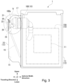
- Fig. 3 is a side view of the air compression device 1 according to the first embodiment viewed from the traveling direction.
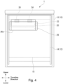
- Fig. 4 is a front view of the air compression device 1 viewed from the outside in the width direction of the vehicle.
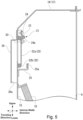
- Fig. 5 is a sectional view (cut along the width direction) of a portion of the air compression device 1 corresponding to the portion V shown in Fig. 3 .
- the air compression device 1 includes a compressor 10 for compressing and discharging the intake air, a cooling fan 11 for sending cooling air to the compressor 10, and a casing 12 that houses the compressor 10 and the cooling fan 11.
- the casing 12 in this embodiment includes a rectangular-parallelepiped-shaped casing body 13 having an opening 9 (see Fig.
- the opening 9 of the casing body 13 is formed in an upper portion of a wall of the one end of the casing body 13. Between the wall of the casing body 13 on the one end and the end cover 14, formed is a main air inlet 15 that opens vertically downward.
- a main air inlet filter 16 is attached to the main air inlet 15 to filter the air (outside air) introduced into the casing 12 through the main air inlet 15.
- the compressor 10 is driven by an electric motor (not shown).
- a scroll-type (structure) of the compressor 10 may be used.
- the compressor 10 of this embodiment includes a compressor body 10A that compresses the intake air and then discharges it, and an air introducing portion 10B that is connected to the suction side of the compressor body 10A and suctions the air that flows into the inside of the casing 12.
- an introducing portion filter 17 is provided inside the air introducing portion 10B to filter the air introduced through an inlet 10Ba of the air introducing portion 10B.
- a discharge pipe 19 (see Figs. 6 and 7 ) connected to an external compressed air tank 18 (see Figs. 6 and 7 ) is connected to a discharge side of the compressor body 10A.
- An auxiliary air inlet 20 that has a horizontally-long-rectangular shape is formed in an upper portion of an end surface of an end cover 14.
- the auxiliary air inlet 20 penetrates a wall of the end cover 14 in the portion facing the opening 9 of the casing body 13 in the vehicle width direction.
- the auxiliary air inlet 20 introduces the outside air into the casing 12.
- An opening-closing mechanism 21 that opens and closes the auxiliary air inlet 20 is attached to the end cover 14.
- the opening-closing mechanism 21 includes a lid 22 that is movable between an opened position in which the auxiliary air inlet 20 is opened and a closed position in which the auxiliary air inlet 20 is closed, and a spring 23 that applies an biasing force to the lid 22 toward the closed position.
- the lid 22 includes a horizontally-long rectangular-shaped plate 22a, which is slightly larger than the auxiliary air inlet 20, and a sealing member 22b disposed around an peripheral edge of the plate 22a.
- An upper edge of the lid 22 is pivotably supported by a portion of the end cover 14 around an upper edge of the auxiliary air inlet 20 inside the casing 12.
- the lid 22 is pivotably attached to the end cover 14 by hinges 24.
- the lid 22 pivots about a support shaft 24a that extends along the upper edge of the auxiliary air inlet 20.
- the hinge 24 is equipped with the aforementioned spring 23 that applies the biasing force to the lid 22.
- the spring 23 is a torsion spring.
- the lid 22 receives the biasing force of the spring 23, and the sealing member 22b disposed in the periphery of the plate 22a tightly contacts the periphery of the auxiliary air inlet 20. In this manner, the lid 22 closes the auxiliary air inlet 20 from the inside of the casing 12. A surface of the lid 22 that faces the inside of the casing 12 is subjected to the pressure of the air inside the casing 12. A surface of the lid 22 that faces the auxiliary air inlet 20 is subjected to the pressure of the outside air (external air) outside the casing 12. The lid 22 opens and closes the auxiliary air inlet 20 depending on the balance between a pressure difference between the inside and the outside of the casing 12 and the biasing force of the spring 23.
- the lid 22 closes the auxiliary air inlet 20 with the biasing force of the spring 23. From this close state, if the pressure difference between the inside and the outside of the casing 12 increases to the predetermined value or more due to an increase in an airflow resistance of the main air inlet filter 16 caused by clogging of the main air inlet filter 16, adhesion of large foreign substances, snow accretion, freezing, etc., the lid 22 of the opening-closing mechanism 21 opens the auxiliary air inlet 20.
- the spring 23 of the hinge 24 serves as a restraining portion for retaining the lid 22 in the closed position.
- the spring 23 quits pressing the lid 22 to the closed position when the pressure difference between the inside and the outside of the casing 12 exceeds the predetermined value.
- a stopper 25 is attached in a portion of the end cover near the lower edge of the auxiliary air inlet 20 to control excessive displacement of the lid 22 in the opening direction to keep the lid 22 inside the casing 12.
- the stopper 25 has a hook portion 25a that bends in an L-shape in the pivot direction of the lid 22 and is disposed at a predetermined distance from the wall of the end cover 14 where the auxiliary air inlet 20 is formed. A part of the hook is situated within the pivoting path of the lid 22.
- the stopper 25 prevents further opening displacement of the lid 22 with the hook portion 25a contacting the lower edge of the lid 22.
- the end cover 14 (casing 12) has a cover 26 that covers the periphery of the auxiliary air inlet 20 from the outside of the end cover 14 and opens downward in the vertical direction.
- the cover 26 covers the auxiliary air inlet 20 from the outside in the vehicle width direction and also from above and from the left and right sides (sides in the traveling direction).
- the lower side of the cover 26 has an opening 26a that opens vertically downward.
- the cooling fan 11 disposed inside the casing 12 sends the outside air that has flowed into the inside of the casing 12 through the main air inlet filter 16 to the compressor 10 as cooling air when the pressure difference between the inside and the outside of the casing 12 does not exceed the predetermined value. Furthermore, when the pressure difference between the inside and the outside of the casing 12 increases to the predetermined value or more due to clogging of the main air inlet filter 16, the cooling fan 11 sends, as cooling air, the outside air that flows in through the auxiliary air inlet 20 opened by the opening-closing mechanism 21 to the compressor 10.
- the intake side of the main air inlet 15 opens such that it faces downward in the vertical direction.
- the intake side of the auxiliary air inlet 20 opens vertically downward through the opening 26a in the cover 26.
- Fig. 6 is a schematic sectional view of the air compression device 1 to illustrate its normally operating state (when the airflow resistance of the main air inlet filter 16 is less than the predetermined value).
- the opening-closing mechanism 21 closes the auxiliary air inlet 20 as shown in Fig. 6 .
- the compressor 10 and the cooling fan 11 operate in this state, the air (outside air) outside the casing 12 is introduced into the casing 12 through the main air inlet filter 16 under suction force by the compressor 10 and the cooling fan 11.
- the air introduced into the casing 12 is suctioned into the compressor body 10A through the air introducing portion 10B of the compressor 10, and is then pressurized in the compressor body 10A and discharged as compressed air.
- the compressed air discharged from the compressor body 10A is provided into the compressed air tank 18 through the discharge pipe 19.
- the outside air passes through the main air inlet filter 16 and is introduced into the casing 12, so relatively large dust particles in the outside air are removed by the main air inlet filter 16. Dusts that pass through pores of the main air inlet filter 16 and enter into the casing 12 are removed by the introducing portion filter 17 disposed in the air introducing portion 10B of the compressor 10.
- the introducing portion filter 17 has a finer mesh than that of the main air inlet filter 16.
- the compressor 10 is cooled by the outside air that has a relatively low temperature. Consequently, the temperature rise in the compressor 10 is suppressed, and a fine compression performance of the compressor 10 is maintained.
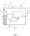
- Fig. 7 is a schematic sectional view of the air compression device 1 to illustrate its operating state when the pressure difference between the inside and the outside of the casing 12 increases to the predetermined value or more.
- the airflow resistance of the main air inlet filter 16 increases, it hinders the introduction of the outside air into the casing 12 through the main air inlet 15. This gradually increases the pressure difference between the inside and the outside of the casing 12.
- a differential pressure between the inside and the outside of the casing 12 surpasses the biasing force of the spring 23 and pushes the lid 22 of the opening-closing mechanism 21 to open as shown in Fig. 7 .
- the auxiliary air inlet 20 of the casing 12 is opened as the lid 22 opens, and the outside air is suctioned into the compressor body 10A from the air introducing portion 10B of the compressor 10 through the auxiliary air inlet 20.
- the compressed air generated in the compressor body 10A is provided into the compressed air tank 18 through the discharge pipe 19.
- an auxiliary filter 35 may be installed at the auxiliary air inlet 20, as illustrated by the double-dashed chain lines in Figs. 6 and 7 .
- the auxiliary filter 35 is preferably coarser than the main air inlet filter 16, for example.
- an open detection sensor 30 may be provided to detect that the lid 22 is opened as shown in Figs. 6 and 7 .
- an open alarm 31 may be activated.
- the open alarm 31 may be any device that is capable of notifying a driver or vehicle manager of the opening of the lid 22, such as a lamp, chime and buzzer.
- the compressor 10 is cooled by the outside air that has a relatively low temperature.
- the air compression device 1 of this embodiment when the airflow resistance of the main air inlet filter 16 increases and the pressure difference between the inside and the outside of the casing 12 exceeds a predetermined value, the auxiliary air inlet 20 of the casing 12 is opened by the opening-closing mechanism 21. Thus, sufficient air can be introduced to the suction side of the compressor 10. Therefore, when the air compression device 1 of this embodiment is employed, even when the airflow resistance of the main air inlet filter 16 increases, it is possible to prevent the load increase of the compressor 10 caused by shortage of the intake air and the delay in filling the compressed air tank 18 with air.
- the opening-closing mechanism 21 includes the lid 22 that can be moved between the opened position and the closed position, and the restraining portion (spring 23) for retaining the lid 22 in the closed position.
- the restraining portion (spring 23) is configured to release its pressing on the lid 22 to the closed position when the pressure difference between the inside and the outside of the casing 12 exceeds the predetermined value.
- the auxiliary air inlet 20 can be opened when the airflow resistance of the main air inlet filter 16 increases, without using an actuator or any other large equipment.
- the spring 23 is used as the restraining portion to keep the lid 22 in the closed position, however, the restraining portion is not limited to the spring 23.
- the restraining portion for retaining the lid 22 in the closed position may be composed of a breakable member that is broken when a load exceeding the predetermined value is applied thereon.
- the lid 22 is configured to open and close the auxiliary air inlet 20 by pivoting on the support shaft 24a of the hinge 24, however the configuration is not limited to this.
- the lid 22 may slide along the wall of the casing 12 to open and close the auxiliary air inlet 20.
- the restraining portion is the spring 23 that biases the lid 22 toward the closed position. Therefore, after the airflow of the main air inlet filter 16 is temporarily reduced due to snow adhesion or the like, the lid 22 can be spontaneously returned to the original closed position when the airflow of the main intake filter 16 is restored. Furthermore, when the spring 23 is used as the restraining portion, the initial pressure of the opening operation of the lid 22 can be easily adjusted by adjusting the initial load of the spring 23, etc.
- the air compression device 1 of the embodiment is provided with the stopper 25 that prevents further opening of the lid 22 when the pressure difference between the inside and the outside of the casing 12 becomes larger than the predetermined value and the displacement of the lid 22 in the opening direction becomes larger than a predetermined amount.
- the stopper 25 prevents excessive opening displacement of the lid 22 when the pressure difference between the inside and the outside of the casing 12 becomes larger than the predetermined value and the displacement of the lid 22 in the opening direction becomes larger than a predetermined amount. Therefore, excessive opening displacement of the lid 22 can be prevented by the stopper 25. Therefore, in the air compression device 1 of the embodiment, interference of the lid 22 with other parts in the casing 12 can be avoided when the auxiliary air inlet 20 is opened, and thereby it is possible to prevent the lid 22 or other components from being damaged.
- the air compression 1 of this embodiment has the cover 26 that is attached to the casing 12 for covering the auxiliary air inlet 20 from outside the casing 12, and the opening 26a of the cover 26 opens vertically downward.
- the cover 26 that is attached to the casing 12 for covering the auxiliary air inlet 20 from outside the casing 12, and the opening 26a of the cover 26 opens vertically downward.
- the cooling fan 11 in the casing 12 when the pressure difference between the inside and the outside of the casing 12 is less than the predetermined value, the cooling fan 11 in the casing 12 sends the outside air that has flowed into the casing 12 through the main air inlet filter 16 as cooling air to the compressor 10.
- the cooling fan 11 inside the casing 12 sends the outside air that has flowed into the casing 12 through the auxiliary air inlet 20 as cooling air to the compressor 10.
- the compressor 10 can be reliably cooled with the outside air, and thereby it is possible to prevent performance degradation of the compressor 10 caused by heat of the compressor 10.
- the air compression device 1 of the embodiment is disposed under the body 100a of the railway vehicle 100. Therefore, running wind can be used to efficiently cool the casing 12 and the air introduced into the casing 12 while the railway vehicle 100 is running.
- the suction side of the auxiliary air inlet 20 opens in the direction orthogonal to the traveling direction of the railway vehicle 100. Therefore, when the auxiliary air inlet 20 is opened while the railway vehicle 100 is running, the running wind can efficiently prevent dust, snow, and the like from entering the auxiliary air inlet 20.
- the auxiliary filter 35 with a lower collection performance than that of the main air inlet filter 16 may be provided at the auxiliary air inlet 20 of the casing 12. In this case, entry of external dust into the casing 12 through the auxiliary air inlet 20 can be more reliably reduced when the auxiliary air inlet 20 is opened.
- the open alarm 31 may be provided to inform that the auxiliary air inlet 20 has been opened by the opening-closing mechanism 21.
- the driver or railway manager can be promptly informed that the main air inlet filter 16 needs to be inspected, replaced, or cleaned.
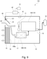
- Figs. 8 and 9 are schematic sectional views of an air compression device 101 of the second embodiment.
- Fig. 8 illustrates an operating state of the air compression device 101 when the pressure difference between the inside and the outside of the casing 12 is less than a predetermined value.
- Fig. 9 illustrates an operating state of the air compression device 101 when the pressure difference between the inside and the outside of the casing 12 is equal to or grater than the predetermined value.
- the air compression device 101 of this embodiment has the same configuration as the air compression device 1 of the first embodiment, except for the configuration of an opening-closing mechanism 121 that opens and closes the auxiliary air inlet 20 of the casing 12. Accordingly, the configuration of the air compression device 101 will be described below, focusing on the opening-closing mechanism 121.
- the opening-closing mechanism 121 includes the lid 22 that is movable between the opened position in which the auxiliary air inlet 20 is opened and the closed position in which the auxiliary air inlet 20 is closed, a pressure sensor 41 that detects the pressure inside the casing 12, and an electric motor 40 that moves the lid 22 to the opened position when the pressure sensor 41 obtains a detection value indicating that the pressure difference between the inside and the outside of the casing 12 has reached the predetermined value or higher.
- the lid 22 is pivotally supported by the casing 12 and is pivoted with a driving force of the motor 40.
- the motor 40 is controlled by a controller 42.
- the pressure sensor 41 is able to detect an increase in the airflow resistance of the main air inlet filter 16. In other words, if the airflow resistance of the main inlet filter 16 increases due to clogging, etc., the pressure in the casing 12 gradually decreases as the airflow resistance increases. Therefore, the increase in the airflow resistance of the main air inlet filter 16 can be determined by checking whether the pressure inside the casing 12 is below a predetermined value.
- the motor 40 serves an actuator that moves the lid 22 between the closed position and the opened position.
- the motor 40 serves as the actuator.
- the actuator is not particularly limited.
- the actuator is not limited to the motor system, but may be a hydraulic actuator or a pneumatic actuator.
- the open alarm 31 is connected to the controller 42.
- the controller 42 controls the motor 40 to move the lid 22 to the opened direction and activates the open alarm 31. This allows the driver or vehicle manager to be notified that the auxiliary air inlet 20 is opened.
- the opening-closing mechanism 121 keeps the auxiliary air inlet 20 closed as shown in Fig. 8 .
- the air (outside air) outside the casing 12 is introduced into the casing 12 through the main air inlet filter 16 under suction force by the compressor 10 and the cooling fan 11.
- the air introduced into the casing 12 is suctioned into the compressor body 10A through the air introducing portion 10B of the compressor 10, and is then pressurized in the compressor body 10A and discharged as compressed air.
- the compressed air discharged from the compressor body 10A is provided into the compressed air tank 18 through the discharge pipe 19.
- the compressor 10 is cooled by the outside air that has a relatively low temperature. Consequently, temperature raise in the compressor 10 is prevented.
- the compression performance of the compressor 10 is well maintained and the compressed air tank 18 can be quickly filled with the compressed air.
- the controller 42 causes the motor 40 in the opening-closing mechanism 121 to move the lid 22 to the opened position as shown in Fig. 9 .
- the auxiliary air inlet 20 of the casing 12 is opened as the lid 22 opens, and the outside air is suctioned into the compressor body 10A from the air introducing portion 10B of the compressor 10 through the auxiliary air inlet 20.
- the compressed air generated in the compressor body 10A is provided into the compressed air tank 18 through the discharge pipe 19.
- the compressor 10 is cooled by the outside air that has a relatively low temperature.
- the air compression device 101 of this embodiment when the airflow resistance of the main air inlet filter 16 increases and the pressure difference between the inside and the outside of the casing 12 reaches to or exceeds the predetermined value, the auxiliary air inlet 20 of the casing 12 is opened by the opening-closing mechanism 121. Thus, sufficient air can be introduced to the suction side of the compressor 10. Therefore, in the air compression device 101 of the second embodiment, even when the airflow resistance of the main air inlet filter 16 increases, it is possible to prevent the load increase of the compressor 10 caused by shortage of the intake air and the delay in filling the compressed air tank 18 with air.
- the sensor detects the increase of the pressure difference between the inside and the outside of the casing 12 (that the pressure difference has reached the predetermined value or higher).
- the lid 22 is configured to be opened by the actuator (motor 40) based on the detection result of the sensor (pressure sensor 41).
- the air compression device 101 of the second embodiment is equipped with the open alarm 31 that notifies that the auxiliary air inlet 20 has been opened by the opening-closing mechanism 121.
- the driver or railway manager can be promptly informed that the main air inlet filter 16 needs to be inspected, replaced, or cleaned.
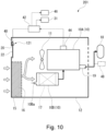
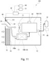
- Figs. 10 and 11 are schematic sectional views of an air compression device 201 of the third embodiment.
- Fig. 10 illustrates an operating state of the air compression device 201 when the pressure difference between the inside and the outside of the casing 12 is less than a predetermined value.
- Fig. 11 illustrates an operating state of the air compression device 201 when the pressure difference between the inside and the outside of the casing 12 is equal to or grater than a predetermined value.
- the air compression device 201 of this embodiment has the same configuration as the air compression device 101 of the second embodiment, except for the configuration of the opening-closing mechanism 121 that opens and closes the auxiliary air inlet 20 of the casing 12. Accordingly, the configuration of the air compression device 201 will be described below, focusing on different features from the opening-closing mechanism 101 of the second embodiment.
- the opening-closing mechanism 121 includes the lid 22 that is movable between the opened position in which the auxiliary air inlet 20 is opened and the closed position in which the auxiliary air inlet 20 is closed, a temperature sensor 44 that senses the temperature of the compressor body 10A of the compressor 10, and the electric motor 40 that moves the lid 22 to the opened position when the temperature sensor 44 obtains a detection value indicating that the pressure difference between the inside and the outside of the casing 12 has reached the predetermined value or higher. It is preferable that the temperature sensor 44 be indirectly fixed to the compressor body 10A and be disposed in the vicinity of the compressor body 10A inside the casing 12. The motor 40 is controlled by the controller 42. When the temperature sensor 44 obtains a detection value indicating that the pressure difference between the inside and the outside of the casing 12 is greater than the predetermined value, the controller 42 controls the motor 40 to move the lid 22 to the opened position (to open the auxiliary air inlet 20).
- the opening-closing mechanism 121 of the third embodiment differs from that of the second embodiment in that a temperature sensor 44 is employed as the sensor to determine that the pressure difference between the inside and the outside of the casing 12 have reached to or exceeds the predetermined value.
- a temperature sensor 44 is employed as the sensor to determine that the pressure difference between the inside and the outside of the casing 12 have reached to or exceeds the predetermined value.
- an increase in the airflow resistance of the introducing portion filter 17 at the air introducing portion 10B of the compressor 10 may also be considered causing the compressor body 10A of the compressor 10 to heat up.
- the controller 42 determines whether the detection value of the temperature sensor 44 is below a predetermined value (a value indicating the increase in the airflow resistance of the main air inlet filter 16).
- the controller 42 activates the introducing portion filter alarm 46 which informs degradation in the ventilation performance of the introducing portion filter 17.
- the temperature sensor 44 is used as the detector to determine whether the pressure difference between the inside and the outside of the casing 12 is equal to or greater than the predetermined value (whether the airflow resistance of the main air inlet filter 16 has reached to or exceeds the predetermined value), but the configuration is not limited to this.
- a flow rate sensor 48 that detects a discharge flow rate of the compressor 10 (illustrated by the double-dashed chain lines in Figs. 10 and 11 ) may be used. In other words, when the airflow resistance of the air inlet filter 16 increases, the discharge flow rate of the compressor 10 decreases as the air-intake resistance increases.
- the flow rate sensor 48 by detecting a change in the discharge flow rate by the flow rate sensor 48, it is also possible to determine whether the pressure difference between the inside and the outside of the casing 12 is equal to or greater than the predetermined value (whether the airflow resistance of the main air inlet filter 16 has increased to the predetermined value).
- the third embodiment can basically produce substantially the same effects as the second embodiment.
- the controller 42 activates the introducing portion filter alarm 46. Therefore, according to the air compression device 201 of the third embodiment, it is possible to notify a driver or vehicle manager that the ventilation performance of the introducing portion filter 17 has decreased without providing a separate dedicated detector for detecting the decrease in the ventilation performance of the introducing portion filter 17.
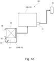
- Fig. 12 is a schematic sectional view of an air compression device 301 of the fourth embodiment.
- the air compression device 301 of the fourth embodiment includes the compressor body 10A that compresses and discharges the intake air, and an intake air introducing portion 310B of the compressor 10 for introducing the air into the compressor body 10A.
- the compressed air tank 18 is connected to the discharge side of the compressor body 10A through the discharge pipe 19.
- the air introducing portion 310B has a main air introducing port 50 and an auxiliary air introducing port 51.
- the introducing portion filter 17, which filters the air introduced into the main air introducing port 50, is disposed downstream of the main air introducing port 50.
- An opening-closing mechanism 321 is provided at the auxiliary air introducing port 51.
- the opening-closing mechanism 321 is equipped with a lid 52 that is movable between an opened position in which the auxiliary air introducing port 51 is opened and a closed position in which the auxiliary air introducing port 51 is closed.
- the opening-closing mechanism 321 closes the auxiliary air introducing port 51 by the lid 52 when the pressure difference between the inside and the outside of the air introducing portion 310B is less than than a predetermined value.
- the opening-closing mechanism 321 opens the auxiliary air introducing port 51 by opening the lid 52 when the pressure difference between the inside and the outside of the air introducing portion 310B has reached to or exceeds the predetermined value.
- the opening-closing mechanism 321 for moving the lid 52 to the opened position and the closed position can be the same as the opening-closing mechanism 21, 121 of the first to third embodiments, for example.
- the lid 52 of the opening-closing mechanism 321 closes the auxiliary air introducing port 51.
- the compressor body 10A operates in this closed state, external air receives a suction force from the compressor body 10A, and the external air is introduced through the introducing portion filter 17 in the air introducing portion 310B.
- the air introduced into the air introducing portion 310B is pressurized in the compressor body 10A and discharged as the compressed air.
- the compressed air discharged from the compressor body 10A is provided into the compressed air tank 18 through the discharge pipe 19.
- the lid 52 of the opening-closing mechanism 321 opens the auxiliary air introducing port 51.
- the compressor body 10A continuously operates in this opened state, the outside air is suctioned into the compressor body 10A through the auxiliary air introducing port 51.
- the compressed air generated in the compressor body 10A is provided into the compressed air tank 18 through the discharge pipe 19.
- the air compression device 301 of the fourth embodiment when the airflow resistance of the introducing portion filter 17 increases and the pressure difference between the inside and the outside of the air introducing portion 310 reaches to or exceeds the predetermined value, the auxiliary air introducing port 51 is opened by the opening-closing mechanism 321. Thus, sufficient air can be introduced to the suction side of the compressor body 10A. Therefore, in the air compression device 301 of the fourth embodiment, even when the airflow resistance of the introducing portion filter 17 increases, it is possible to prevent the load increase of the compressor 10 caused by shortage of the intake air and the delay in filling the compressed air tank 18 with air.
- the embodiments of the air compression device have been described, but by changing the compressor 10 in each embodiment to a suction unit, it is possible to obtain a suction device that is not used for supply the compressed air to a target.
- An embodiment of the suction device can be obtained by replacing the terms in each of the above embodiments of the air compression device with the following.
- the suction device of each embodiment thus obtained can have the same effect as each of the above embodiments of the air compression device.
Landscapes
- Engineering & Computer Science (AREA)
- Mechanical Engineering (AREA)
- General Engineering & Computer Science (AREA)
- Computer Hardware Design (AREA)
- Compressor (AREA)
- Compressors, Vaccum Pumps And Other Relevant Systems (AREA)
- Control Of Positive-Displacement Pumps (AREA)
- Applications Or Details Of Rotary Compressors (AREA)
Applications Claiming Priority (1)
| Application Number | Priority Date | Filing Date | Title |
|---|---|---|---|
| JP2020191648A JP7654385B2 (ja) | 2020-11-18 | 2020-11-18 | 空気圧縮装置、及び、空気吸引装置 |
Publications (2)
| Publication Number | Publication Date |
|---|---|
| EP4001648A1 EP4001648A1 (en) | 2022-05-25 |
| EP4001648B1 true EP4001648B1 (en) | 2023-12-27 |
Family
ID=78087254
Family Applications (1)
| Application Number | Title | Priority Date | Filing Date |
|---|---|---|---|
| EP21202060.6A Active EP4001648B1 (en) | 2020-11-18 | 2021-10-12 | Air compression device and air suction device |
Country Status (3)
| Country | Link |
|---|---|
| EP (1) | EP4001648B1 (enExample) |
| JP (1) | JP7654385B2 (enExample) |
| CN (1) | CN114517783A (enExample) |
Family Cites Families (30)
| Publication number | Priority date | Publication date | Assignee | Title |
|---|---|---|---|---|
| US3369736A (en) * | 1966-04-26 | 1968-02-20 | Worthington Corp | Forced ventilation for motor cooling on enclosed motor driven compressor unit |
| JPS6041591U (ja) * | 1983-08-30 | 1985-03-23 | 日東工器株式会社 | コンプレツサ−容器 |
| JPH10339225A (ja) * | 1997-06-10 | 1998-12-22 | Toyota Motor Corp | 車載内燃機関の吸気装置 |
| JPH11324708A (ja) * | 1998-05-19 | 1999-11-26 | Mitsubishi Heavy Ind Ltd | ガスタービンインレットフィルタ装置 |
| JPH11342720A (ja) * | 1998-06-01 | 1999-12-14 | Mitsubishi Heavy Ind Ltd | 空気調和ユニット及び車両用空気調和装置 |
| KR101123316B1 (ko) * | 2004-08-16 | 2012-03-20 | 엘지전자 주식회사 | 공기조화기 |
| GB0521332D0 (en) * | 2005-10-20 | 2005-11-30 | Rolls Royce Plc | A gas feed assembly |
| DE102006030227B3 (de) * | 2006-06-30 | 2008-03-27 | BSH Bosch und Siemens Hausgeräte GmbH | Nebenluftventil |
| JP2008214109A (ja) | 2007-02-28 | 2008-09-18 | Terumo Corp | 酸素濃縮装置 |
| DE102007050986A1 (de) * | 2007-10-25 | 2009-04-30 | Robert Bosch Gmbh | Verdichterzuschaltventil und Registeraufladeeinrichtung mit einem solchen Verdichterzuschaltventil |
| US20090155106A1 (en) * | 2007-12-12 | 2009-06-18 | Caterpillar Inc. | Extended compressor operation for auxiliary air supply |
| JP2009192878A (ja) * | 2008-02-15 | 2009-08-27 | Seiko Epson Corp | プロジェクタ |
| JP5500805B2 (ja) * | 2008-09-02 | 2014-05-21 | 株式会社ヴァレオジャパン | 車両用空調装置 |
| CN101539315A (zh) | 2009-04-23 | 2009-09-23 | 广东美的电器股份有限公司 | 空气调节器室内机及其运行模式 |
| JP5488111B2 (ja) * | 2010-03-29 | 2014-05-14 | セイコーエプソン株式会社 | プロジェクター |
| JP6076116B2 (ja) | 2013-02-12 | 2017-02-08 | 三菱電機株式会社 | 空気圧縮装置及び潤滑油劣化報知方法 |
| KR102315344B1 (ko) * | 2014-03-18 | 2021-10-21 | 삼성전자주식회사 | 공기조화기 및 공기조화기의 제어방법 |
| JP2016089665A (ja) * | 2014-10-31 | 2016-05-23 | 株式会社Ihi | パッケージ形水潤滑式スクリュ圧縮機 |
| JP6385816B2 (ja) | 2014-12-25 | 2018-09-05 | 株式会社日立製作所 | 電力変換装置及びこれを備えた鉄道車両 |
| JP2016133013A (ja) * | 2015-01-16 | 2016-07-25 | 株式会社神戸製鋼所 | 空冷式パッケージ形圧縮機 |
| US10711777B2 (en) * | 2015-03-19 | 2020-07-14 | Embraco Industria De Compressores E Solucoes Em Refrigeracao Ltda | Suction acoustic filter for compressor |
| JP5997810B1 (ja) * | 2015-06-30 | 2016-09-28 | 本田技研工業株式会社 | エンジンの吸気構造 |
| JP6571422B2 (ja) * | 2015-07-03 | 2019-09-04 | 株式会社神戸製鋼所 | パッケージ型空冷式スクリュー圧縮機 |
| JP2017080707A (ja) | 2015-10-30 | 2017-05-18 | パナソニックIpマネジメント株式会社 | 空気清浄機 |
| JP2017217988A (ja) * | 2016-06-06 | 2017-12-14 | 株式会社日立製作所 | 車両用換気装置及びこれを備えた鉄道車両 |
| JP6920901B2 (ja) * | 2017-06-30 | 2021-08-18 | ハイリマレリジャパン株式会社 | 空調装置 |
| JP2021014790A (ja) | 2017-10-27 | 2021-02-12 | 株式会社日立産機システム | 空気圧縮機 |
| CN110360116A (zh) * | 2019-08-30 | 2019-10-22 | 湖北特威特动力科技股份有限公司 | 螺杆空压机 |
| CN110905774B (zh) | 2019-12-11 | 2021-08-31 | 珠海格力节能环保制冷技术研究中心有限公司 | 阀组件、压缩机及电器 |
| KR102276103B1 (ko) * | 2021-03-08 | 2021-07-12 | 한국에어로(주) | 필터 청소기능과 난방 기능을 갖는 공기 압축 시스템 |
-
2020
- 2020-11-18 JP JP2020191648A patent/JP7654385B2/ja active Active
-
2021
- 2021-10-12 EP EP21202060.6A patent/EP4001648B1/en active Active
- 2021-10-14 CN CN202111196143.0A patent/CN114517783A/zh active Pending
Also Published As
| Publication number | Publication date |
|---|---|
| JP2022080522A (ja) | 2022-05-30 |
| JP7654385B2 (ja) | 2025-04-01 |
| CN114517783A (zh) | 2022-05-20 |
| EP4001648A1 (en) | 2022-05-25 |
Similar Documents
| Publication | Publication Date | Title |
|---|---|---|
| US4312645A (en) | Separator assembly | |
| US20070186774A1 (en) | Multistage air cleaner including pulse cleaning system | |
| US8840709B2 (en) | Method and apparatus for purifying compressed air | |
| US20210023489A1 (en) | Oil separator and compressed air drying system | |
| US7285149B2 (en) | Oil separator for vehicle air system | |
| US20090088065A1 (en) | Air extractor to prevent wind throb in automobiles | |
| JP7341625B2 (ja) | 吸引装置、及び吸引車 | |
| EP4001648B1 (en) | Air compression device and air suction device | |
| WO2012017939A1 (ja) | 鉄道車両用空気圧縮装置 | |
| KR20170059892A (ko) | 저장실 청소 밸브 | |
| CA2530807C (en) | Drain valve | |
| US4726823A (en) | Movable filter assembly for automotive air handling assembly | |
| CA2834016C (en) | Compressed air supply apparatus | |
| KR100565555B1 (ko) | 공기상태 제어유니트 | |
| CN101626935B (zh) | 使用于有轨机车空调机的空气预处理装置 | |
| US5254033A (en) | Automatically released air inlet filter | |
| WO2017094758A1 (ja) | 気液分離装置 | |
| EP0075054B1 (en) | Improved separator assembly | |
| CN112261983A (zh) | 带有关闭装置的空气过滤器壳体、空气过滤器和车辆 | |
| JP3800772B2 (ja) | 車両用天井置きクーラユニット | |
| CN217355574U (zh) | 防尘结构及电磁阀 | |
| JPS5858124A (ja) | 分離装置組立体 | |
| KR101028207B1 (ko) | 바이패스 통로가 설치된 차량용 공조장치 | |
| JP2017217988A (ja) | 車両用換気装置及びこれを備えた鉄道車両 | |
| JP7410227B2 (ja) | オイルセパレータ |
Legal Events
| Date | Code | Title | Description |
|---|---|---|---|
| PUAI | Public reference made under article 153(3) epc to a published international application that has entered the european phase |
Free format text: ORIGINAL CODE: 0009012 |
|
| STAA | Information on the status of an ep patent application or granted ep patent |
Free format text: STATUS: REQUEST FOR EXAMINATION WAS MADE |
|
| 17P | Request for examination filed |
Effective date: 20211012 |
|
| AK | Designated contracting states |
Kind code of ref document: A1 Designated state(s): AL AT BE BG CH CY CZ DE DK EE ES FI FR GB GR HR HU IE IS IT LI LT LU LV MC MK MT NL NO PL PT RO RS SE SI SK SM TR |
|
| RBV | Designated contracting states (corrected) |
Designated state(s): AL AT BE BG CH CY CZ DE DK EE ES FI FR GB GR HR HU IE IS IT LI LT LU LV MC MK MT NL NO PL PT RO RS SE SI SK SM TR |
|
| P01 | Opt-out of the competence of the unified patent court (upc) registered |
Effective date: 20230523 |
|
| GRAP | Despatch of communication of intention to grant a patent |
Free format text: ORIGINAL CODE: EPIDOSNIGR1 |
|
| STAA | Information on the status of an ep patent application or granted ep patent |
Free format text: STATUS: GRANT OF PATENT IS INTENDED |
|
| RIC1 | Information provided on ipc code assigned before grant |
Ipc: F04C 29/12 20060101ALI20230726BHEP Ipc: F04B 39/16 20060101ALI20230726BHEP Ipc: F04B 49/06 20060101ALI20230726BHEP Ipc: F04B 53/10 20060101ALI20230726BHEP Ipc: F04B 53/16 20060101ALI20230726BHEP Ipc: F04B 53/20 20060101ALI20230726BHEP Ipc: F04C 29/00 20060101ALI20230726BHEP Ipc: F04B 35/06 20060101AFI20230726BHEP |
|
| INTG | Intention to grant announced |
Effective date: 20230810 |
|
| GRAS | Grant fee paid |
Free format text: ORIGINAL CODE: EPIDOSNIGR3 |
|
| GRAA | (expected) grant |
Free format text: ORIGINAL CODE: 0009210 |
|
| STAA | Information on the status of an ep patent application or granted ep patent |
Free format text: STATUS: THE PATENT HAS BEEN GRANTED |
|
| AK | Designated contracting states |
Kind code of ref document: B1 Designated state(s): AL AT BE BG CH CY CZ DE DK EE ES FI FR GB GR HR HU IE IS IT LI LT LU LV MC MK MT NL NO PL PT RO RS SE SI SK SM TR |
|
| REG | Reference to a national code |
Ref country code: GB Ref legal event code: FG4D |
|
| REG | Reference to a national code |
Ref country code: CH Ref legal event code: EP |
|
| REG | Reference to a national code |
Ref country code: DE Ref legal event code: R096 Ref document number: 602021008065 Country of ref document: DE |
|
| REG | Reference to a national code |
Ref country code: IE Ref legal event code: FG4D |
|
| PG25 | Lapsed in a contracting state [announced via postgrant information from national office to epo] |
Ref country code: GR Free format text: LAPSE BECAUSE OF FAILURE TO SUBMIT A TRANSLATION OF THE DESCRIPTION OR TO PAY THE FEE WITHIN THE PRESCRIBED TIME-LIMIT Effective date: 20240328 |
|
| REG | Reference to a national code |
Ref country code: LT Ref legal event code: MG9D |
|
| PG25 | Lapsed in a contracting state [announced via postgrant information from national office to epo] |
Ref country code: LT Free format text: LAPSE BECAUSE OF FAILURE TO SUBMIT A TRANSLATION OF THE DESCRIPTION OR TO PAY THE FEE WITHIN THE PRESCRIBED TIME-LIMIT Effective date: 20231227 |
|
| PG25 | Lapsed in a contracting state [announced via postgrant information from national office to epo] |
Ref country code: ES Free format text: LAPSE BECAUSE OF FAILURE TO SUBMIT A TRANSLATION OF THE DESCRIPTION OR TO PAY THE FEE WITHIN THE PRESCRIBED TIME-LIMIT Effective date: 20231227 |
|
| PG25 | Lapsed in a contracting state [announced via postgrant information from national office to epo] |
Ref country code: LT Free format text: LAPSE BECAUSE OF FAILURE TO SUBMIT A TRANSLATION OF THE DESCRIPTION OR TO PAY THE FEE WITHIN THE PRESCRIBED TIME-LIMIT Effective date: 20231227 Ref country code: GR Free format text: LAPSE BECAUSE OF FAILURE TO SUBMIT A TRANSLATION OF THE DESCRIPTION OR TO PAY THE FEE WITHIN THE PRESCRIBED TIME-LIMIT Effective date: 20240328 Ref country code: FI Free format text: LAPSE BECAUSE OF FAILURE TO SUBMIT A TRANSLATION OF THE DESCRIPTION OR TO PAY THE FEE WITHIN THE PRESCRIBED TIME-LIMIT Effective date: 20231227 Ref country code: ES Free format text: LAPSE BECAUSE OF FAILURE TO SUBMIT A TRANSLATION OF THE DESCRIPTION OR TO PAY THE FEE WITHIN THE PRESCRIBED TIME-LIMIT Effective date: 20231227 Ref country code: BG Free format text: LAPSE BECAUSE OF FAILURE TO SUBMIT A TRANSLATION OF THE DESCRIPTION OR TO PAY THE FEE WITHIN THE PRESCRIBED TIME-LIMIT Effective date: 20240327 |
|
| REG | Reference to a national code |
Ref country code: NL Ref legal event code: MP Effective date: 20231227 |
|
| REG | Reference to a national code |
Ref country code: AT Ref legal event code: MK05 Ref document number: 1644753 Country of ref document: AT Kind code of ref document: T Effective date: 20231227 |
|
| PG25 | Lapsed in a contracting state [announced via postgrant information from national office to epo] |
Ref country code: NL Free format text: LAPSE BECAUSE OF FAILURE TO SUBMIT A TRANSLATION OF THE DESCRIPTION OR TO PAY THE FEE WITHIN THE PRESCRIBED TIME-LIMIT Effective date: 20231227 |
|
| PG25 | Lapsed in a contracting state [announced via postgrant information from national office to epo] |
Ref country code: SE Free format text: LAPSE BECAUSE OF FAILURE TO SUBMIT A TRANSLATION OF THE DESCRIPTION OR TO PAY THE FEE WITHIN THE PRESCRIBED TIME-LIMIT Effective date: 20231227 Ref country code: RS Free format text: LAPSE BECAUSE OF FAILURE TO SUBMIT A TRANSLATION OF THE DESCRIPTION OR TO PAY THE FEE WITHIN THE PRESCRIBED TIME-LIMIT Effective date: 20231227 Ref country code: NO Free format text: LAPSE BECAUSE OF FAILURE TO SUBMIT A TRANSLATION OF THE DESCRIPTION OR TO PAY THE FEE WITHIN THE PRESCRIBED TIME-LIMIT Effective date: 20240327 Ref country code: NL Free format text: LAPSE BECAUSE OF FAILURE TO SUBMIT A TRANSLATION OF THE DESCRIPTION OR TO PAY THE FEE WITHIN THE PRESCRIBED TIME-LIMIT Effective date: 20231227 Ref country code: LV Free format text: LAPSE BECAUSE OF FAILURE TO SUBMIT A TRANSLATION OF THE DESCRIPTION OR TO PAY THE FEE WITHIN THE PRESCRIBED TIME-LIMIT Effective date: 20231227 Ref country code: HR Free format text: LAPSE BECAUSE OF FAILURE TO SUBMIT A TRANSLATION OF THE DESCRIPTION OR TO PAY THE FEE WITHIN THE PRESCRIBED TIME-LIMIT Effective date: 20231227 |
|
| PG25 | Lapsed in a contracting state [announced via postgrant information from national office to epo] |
Ref country code: IS Free format text: LAPSE BECAUSE OF FAILURE TO SUBMIT A TRANSLATION OF THE DESCRIPTION OR TO PAY THE FEE WITHIN THE PRESCRIBED TIME-LIMIT Effective date: 20240427 |
|
| PG25 | Lapsed in a contracting state [announced via postgrant information from national office to epo] |
Ref country code: AT Free format text: LAPSE BECAUSE OF FAILURE TO SUBMIT A TRANSLATION OF THE DESCRIPTION OR TO PAY THE FEE WITHIN THE PRESCRIBED TIME-LIMIT Effective date: 20231227 Ref country code: CZ Free format text: LAPSE BECAUSE OF FAILURE TO SUBMIT A TRANSLATION OF THE DESCRIPTION OR TO PAY THE FEE WITHIN THE PRESCRIBED TIME-LIMIT Effective date: 20231227 |
|
| PG25 | Lapsed in a contracting state [announced via postgrant information from national office to epo] |
Ref country code: SK Free format text: LAPSE BECAUSE OF FAILURE TO SUBMIT A TRANSLATION OF THE DESCRIPTION OR TO PAY THE FEE WITHIN THE PRESCRIBED TIME-LIMIT Effective date: 20231227 |
|
| PG25 | Lapsed in a contracting state [announced via postgrant information from national office to epo] |
Ref country code: SM Free format text: LAPSE BECAUSE OF FAILURE TO SUBMIT A TRANSLATION OF THE DESCRIPTION OR TO PAY THE FEE WITHIN THE PRESCRIBED TIME-LIMIT Effective date: 20231227 Ref country code: SK Free format text: LAPSE BECAUSE OF FAILURE TO SUBMIT A TRANSLATION OF THE DESCRIPTION OR TO PAY THE FEE WITHIN THE PRESCRIBED TIME-LIMIT Effective date: 20231227 Ref country code: RO Free format text: LAPSE BECAUSE OF FAILURE TO SUBMIT A TRANSLATION OF THE DESCRIPTION OR TO PAY THE FEE WITHIN THE PRESCRIBED TIME-LIMIT Effective date: 20231227 Ref country code: IT Free format text: LAPSE BECAUSE OF FAILURE TO SUBMIT A TRANSLATION OF THE DESCRIPTION OR TO PAY THE FEE WITHIN THE PRESCRIBED TIME-LIMIT Effective date: 20231227 Ref country code: IS Free format text: LAPSE BECAUSE OF FAILURE TO SUBMIT A TRANSLATION OF THE DESCRIPTION OR TO PAY THE FEE WITHIN THE PRESCRIBED TIME-LIMIT Effective date: 20240427 Ref country code: EE Free format text: LAPSE BECAUSE OF FAILURE TO SUBMIT A TRANSLATION OF THE DESCRIPTION OR TO PAY THE FEE WITHIN THE PRESCRIBED TIME-LIMIT Effective date: 20231227 Ref country code: CZ Free format text: LAPSE BECAUSE OF FAILURE TO SUBMIT A TRANSLATION OF THE DESCRIPTION OR TO PAY THE FEE WITHIN THE PRESCRIBED TIME-LIMIT Effective date: 20231227 Ref country code: AT Free format text: LAPSE BECAUSE OF FAILURE TO SUBMIT A TRANSLATION OF THE DESCRIPTION OR TO PAY THE FEE WITHIN THE PRESCRIBED TIME-LIMIT Effective date: 20231227 |
|
| PG25 | Lapsed in a contracting state [announced via postgrant information from national office to epo] |
Ref country code: PT Free format text: LAPSE BECAUSE OF FAILURE TO SUBMIT A TRANSLATION OF THE DESCRIPTION OR TO PAY THE FEE WITHIN THE PRESCRIBED TIME-LIMIT Effective date: 20240429 Ref country code: PL Free format text: LAPSE BECAUSE OF FAILURE TO SUBMIT A TRANSLATION OF THE DESCRIPTION OR TO PAY THE FEE WITHIN THE PRESCRIBED TIME-LIMIT Effective date: 20231227 |
|
| REG | Reference to a national code |
Ref country code: DE Ref legal event code: R097 Ref document number: 602021008065 Country of ref document: DE |
|
| PG25 | Lapsed in a contracting state [announced via postgrant information from national office to epo] |
Ref country code: DK Free format text: LAPSE BECAUSE OF FAILURE TO SUBMIT A TRANSLATION OF THE DESCRIPTION OR TO PAY THE FEE WITHIN THE PRESCRIBED TIME-LIMIT Effective date: 20231227 |
|
| PG25 | Lapsed in a contracting state [announced via postgrant information from national office to epo] |
Ref country code: DK Free format text: LAPSE BECAUSE OF FAILURE TO SUBMIT A TRANSLATION OF THE DESCRIPTION OR TO PAY THE FEE WITHIN THE PRESCRIBED TIME-LIMIT Effective date: 20231227 |
|
| PLBE | No opposition filed within time limit |
Free format text: ORIGINAL CODE: 0009261 |
|
| STAA | Information on the status of an ep patent application or granted ep patent |
Free format text: STATUS: NO OPPOSITION FILED WITHIN TIME LIMIT |
|
| 26N | No opposition filed |
Effective date: 20240930 |
|
| PGFP | Annual fee paid to national office [announced via postgrant information from national office to epo] |
Ref country code: DE Payment date: 20241021 Year of fee payment: 4 |
|
| PGFP | Annual fee paid to national office [announced via postgrant information from national office to epo] |
Ref country code: FR Payment date: 20241030 Year of fee payment: 4 |
|
| PG25 | Lapsed in a contracting state [announced via postgrant information from national office to epo] |
Ref country code: SI Free format text: LAPSE BECAUSE OF FAILURE TO SUBMIT A TRANSLATION OF THE DESCRIPTION OR TO PAY THE FEE WITHIN THE PRESCRIBED TIME-LIMIT Effective date: 20231227 |
|
| REG | Reference to a national code |
Ref country code: CH Ref legal event code: PL |
|
| PG25 | Lapsed in a contracting state [announced via postgrant information from national office to epo] |
Ref country code: MC Free format text: LAPSE BECAUSE OF FAILURE TO SUBMIT A TRANSLATION OF THE DESCRIPTION OR TO PAY THE FEE WITHIN THE PRESCRIBED TIME-LIMIT Effective date: 20231227 |
|
| PG25 | Lapsed in a contracting state [announced via postgrant information from national office to epo] |
Ref country code: LU Free format text: LAPSE BECAUSE OF NON-PAYMENT OF DUE FEES Effective date: 20241012 Ref country code: BE Free format text: LAPSE BECAUSE OF NON-PAYMENT OF DUE FEES Effective date: 20241031 |
|
| PG25 | Lapsed in a contracting state [announced via postgrant information from national office to epo] |
Ref country code: CH Free format text: LAPSE BECAUSE OF NON-PAYMENT OF DUE FEES Effective date: 20241031 |
|
| REG | Reference to a national code |
Ref country code: BE Ref legal event code: MM Effective date: 20241031 |
|
| PG25 | Lapsed in a contracting state [announced via postgrant information from national office to epo] |
Ref country code: IE Free format text: LAPSE BECAUSE OF NON-PAYMENT OF DUE FEES Effective date: 20241012 |