EP3978792A1 - Handheld gimbal - Google Patents
Handheld gimbal Download PDFInfo
- Publication number
- EP3978792A1 EP3978792A1 EP19930491.6A EP19930491A EP3978792A1 EP 3978792 A1 EP3978792 A1 EP 3978792A1 EP 19930491 A EP19930491 A EP 19930491A EP 3978792 A1 EP3978792 A1 EP 3978792A1
- Authority
- EP
- European Patent Office
- Prior art keywords
- shaft arm
- motor
- handheld gimbal
- slot
- rotation
- Prior art date
- Legal status (The legal status is an assumption and is not a legal conclusion. Google has not performed a legal analysis and makes no representation as to the accuracy of the status listed.)
- Withdrawn
Links
Images


Classifications
-
- G—PHYSICS
- G03—PHOTOGRAPHY; CINEMATOGRAPHY; ANALOGOUS TECHNIQUES USING WAVES OTHER THAN OPTICAL WAVES; ELECTROGRAPHY; HOLOGRAPHY
- G03B—APPARATUS OR ARRANGEMENTS FOR TAKING PHOTOGRAPHS OR FOR PROJECTING OR VIEWING THEM; APPARATUS OR ARRANGEMENTS EMPLOYING ANALOGOUS TECHNIQUES USING WAVES OTHER THAN OPTICAL WAVES; ACCESSORIES THEREFOR
- G03B17/00—Details of cameras or camera bodies; Accessories therefor
- G03B17/56—Accessories
- G03B17/563—Camera grips, handles
-
- F—MECHANICAL ENGINEERING; LIGHTING; HEATING; WEAPONS; BLASTING
- F16—ENGINEERING ELEMENTS AND UNITS; GENERAL MEASURES FOR PRODUCING AND MAINTAINING EFFECTIVE FUNCTIONING OF MACHINES OR INSTALLATIONS; THERMAL INSULATION IN GENERAL
- F16C—SHAFTS; FLEXIBLE SHAFTS; ELEMENTS OR CRANKSHAFT MECHANISMS; ROTARY BODIES OTHER THAN GEARING ELEMENTS; BEARINGS
- F16C11/00—Pivots; Pivotal connections
- F16C11/04—Pivotal connections
- F16C11/10—Arrangements for locking
-
- F—MECHANICAL ENGINEERING; LIGHTING; HEATING; WEAPONS; BLASTING
- F16—ENGINEERING ELEMENTS AND UNITS; GENERAL MEASURES FOR PRODUCING AND MAINTAINING EFFECTIVE FUNCTIONING OF MACHINES OR INSTALLATIONS; THERMAL INSULATION IN GENERAL
- F16C—SHAFTS; FLEXIBLE SHAFTS; ELEMENTS OR CRANKSHAFT MECHANISMS; ROTARY BODIES OTHER THAN GEARING ELEMENTS; BEARINGS
- F16C11/00—Pivots; Pivotal connections
- F16C11/04—Pivotal connections
- F16C11/12—Pivotal connections incorporating flexible connections, e.g. leaf springs
-
- F—MECHANICAL ENGINEERING; LIGHTING; HEATING; WEAPONS; BLASTING
- F16—ENGINEERING ELEMENTS AND UNITS; GENERAL MEASURES FOR PRODUCING AND MAINTAINING EFFECTIVE FUNCTIONING OF MACHINES OR INSTALLATIONS; THERMAL INSULATION IN GENERAL
- F16M—FRAMES, CASINGS OR BEDS OF ENGINES, MACHINES OR APPARATUS, NOT SPECIFIC TO ENGINES, MACHINES OR APPARATUS PROVIDED FOR ELSEWHERE; STANDS; SUPPORTS
- F16M11/00—Stands or trestles as supports for apparatus or articles placed thereon Stands for scientific apparatus such as gravitational force meters
- F16M11/02—Heads
- F16M11/04—Means for attachment of apparatus; Means allowing adjustment of the apparatus relatively to the stand
- F16M11/06—Means for attachment of apparatus; Means allowing adjustment of the apparatus relatively to the stand allowing pivoting
- F16M11/12—Means for attachment of apparatus; Means allowing adjustment of the apparatus relatively to the stand allowing pivoting in more than one direction
- F16M11/121—Means for attachment of apparatus; Means allowing adjustment of the apparatus relatively to the stand allowing pivoting in more than one direction constituted of several dependent joints
- F16M11/123—Means for attachment of apparatus; Means allowing adjustment of the apparatus relatively to the stand allowing pivoting in more than one direction constituted of several dependent joints the axis of rotation intersecting in a single point, e.g. by using gimbals
-
- F—MECHANICAL ENGINEERING; LIGHTING; HEATING; WEAPONS; BLASTING
- F16—ENGINEERING ELEMENTS AND UNITS; GENERAL MEASURES FOR PRODUCING AND MAINTAINING EFFECTIVE FUNCTIONING OF MACHINES OR INSTALLATIONS; THERMAL INSULATION IN GENERAL
- F16M—FRAMES, CASINGS OR BEDS OF ENGINES, MACHINES OR APPARATUS, NOT SPECIFIC TO ENGINES, MACHINES OR APPARATUS PROVIDED FOR ELSEWHERE; STANDS; SUPPORTS
- F16M11/00—Stands or trestles as supports for apparatus or articles placed thereon Stands for scientific apparatus such as gravitational force meters
- F16M11/02—Heads
- F16M11/18—Heads with mechanism for moving the apparatus relatively to the stand
-
- F—MECHANICAL ENGINEERING; LIGHTING; HEATING; WEAPONS; BLASTING
- F16—ENGINEERING ELEMENTS AND UNITS; GENERAL MEASURES FOR PRODUCING AND MAINTAINING EFFECTIVE FUNCTIONING OF MACHINES OR INSTALLATIONS; THERMAL INSULATION IN GENERAL
- F16M—FRAMES, CASINGS OR BEDS OF ENGINES, MACHINES OR APPARATUS, NOT SPECIFIC TO ENGINES, MACHINES OR APPARATUS PROVIDED FOR ELSEWHERE; STANDS; SUPPORTS
- F16M13/00—Other supports for positioning apparatus or articles; Means for steadying hand-held apparatus or articles
- F16M13/02—Other supports for positioning apparatus or articles; Means for steadying hand-held apparatus or articles for supporting on, or attaching to, an object, e.g. tree, gate, window-frame, cycle
-
- F—MECHANICAL ENGINEERING; LIGHTING; HEATING; WEAPONS; BLASTING
- F16—ENGINEERING ELEMENTS AND UNITS; GENERAL MEASURES FOR PRODUCING AND MAINTAINING EFFECTIVE FUNCTIONING OF MACHINES OR INSTALLATIONS; THERMAL INSULATION IN GENERAL
- F16M—FRAMES, CASINGS OR BEDS OF ENGINES, MACHINES OR APPARATUS, NOT SPECIFIC TO ENGINES, MACHINES OR APPARATUS PROVIDED FOR ELSEWHERE; STANDS; SUPPORTS
- F16M13/00—Other supports for positioning apparatus or articles; Means for steadying hand-held apparatus or articles
- F16M13/04—Other supports for positioning apparatus or articles; Means for steadying hand-held apparatus or articles for supporting on, or holding steady relative to, a person, e.g. by chains, e.g. rifle butt or pistol grip supports, supports attached to the chest or head
-
- G—PHYSICS
- G03—PHOTOGRAPHY; CINEMATOGRAPHY; ANALOGOUS TECHNIQUES USING WAVES OTHER THAN OPTICAL WAVES; ELECTROGRAPHY; HOLOGRAPHY
- G03B—APPARATUS OR ARRANGEMENTS FOR TAKING PHOTOGRAPHS OR FOR PROJECTING OR VIEWING THEM; APPARATUS OR ARRANGEMENTS EMPLOYING ANALOGOUS TECHNIQUES USING WAVES OTHER THAN OPTICAL WAVES; ACCESSORIES THEREFOR
- G03B17/00—Details of cameras or camera bodies; Accessories therefor
- G03B17/56—Accessories
- G03B17/561—Support related camera accessories
-
- H—ELECTRICITY
- H04—ELECTRIC COMMUNICATION TECHNIQUE
- H04M—TELEPHONIC COMMUNICATION
- H04M1/00—Substation equipment, e.g. for use by subscribers
- H04M1/02—Constructional features of telephone sets
- H04M1/04—Supports for telephone transmitters or receivers
-
- F—MECHANICAL ENGINEERING; LIGHTING; HEATING; WEAPONS; BLASTING
- F16—ENGINEERING ELEMENTS AND UNITS; GENERAL MEASURES FOR PRODUCING AND MAINTAINING EFFECTIVE FUNCTIONING OF MACHINES OR INSTALLATIONS; THERMAL INSULATION IN GENERAL
- F16M—FRAMES, CASINGS OR BEDS OF ENGINES, MACHINES OR APPARATUS, NOT SPECIFIC TO ENGINES, MACHINES OR APPARATUS PROVIDED FOR ELSEWHERE; STANDS; SUPPORTS
- F16M2200/00—Details of stands or supports
- F16M2200/02—Locking means
- F16M2200/021—Locking means for rotational movement
-
- F—MECHANICAL ENGINEERING; LIGHTING; HEATING; WEAPONS; BLASTING
- F16—ENGINEERING ELEMENTS AND UNITS; GENERAL MEASURES FOR PRODUCING AND MAINTAINING EFFECTIVE FUNCTIONING OF MACHINES OR INSTALLATIONS; THERMAL INSULATION IN GENERAL
- F16M—FRAMES, CASINGS OR BEDS OF ENGINES, MACHINES OR APPARATUS, NOT SPECIFIC TO ENGINES, MACHINES OR APPARATUS PROVIDED FOR ELSEWHERE; STANDS; SUPPORTS
- F16M2200/00—Details of stands or supports
- F16M2200/04—Balancing means
- F16M2200/041—Balancing means for balancing rotational movement of the head
Definitions
- the present invention relates to the gimbal field, and in particular, to a handheld gimbal.
- a patented utility model with publication No. CN208253098U discloses a handheld stabilizer.
- one end of a first connecting portion is hinged to an upper end of a handle, and another other end of the first connecting arm is hinged to one end of a second connecting arm.
- the first connecting arm can be folded downward, and after the folding, a total length of the handheld stabilizer is reduced.
- the second connecting arm keeps parallel with the handle, and a clamping portion is located between the handle and the second connecting arm. This reduces a total volume of the handheld stabilizer, and makes it convenient to store and carry the handheld stabilizer.
- the present invention provides a handheld gimbal.
- a handheld gimbal including:
- a handheld gimbal including:
- a handheld gimbal including:
- a handheld gimbal including:
- the handheld gimbal of the present invention can change the shape of the handheld gimbal by means of the cooperation between various structures, so that when the handheld gimbal is stored, the gaps between these structures become smaller, and thus making the handheld gimbal more compact in storage.
- the carrier of the handheld gimbal of the present invention will not be limited between the shaft arm(s) and the handle after folding, which is beneficial to the storage of the handheld gimbal, helps the switch between the use state and the storage state of the handheld gimbal.
- the folding structure is compact, the operation is sample, and the storage is convenient.
- a handheld gimbal may include a handle and a stabilizing gimbal mechanism connected to the handle, where the stabilizing gimbal mechanism includes a first shaft assembly, a second shaft assembly, a third shaft assembly, a holder, and a rotatable connecting member.
- the stabilizing gimbal can be not only detachably connected to the handle, but also detachably connected to another vehicle, for example, an unmanned aircraft, a vehicle, or a remotely controlled ground vehicle.
- the stabilizing gimbal mechanism may be quickly connected to the foregoing vehicles, so that the stabilizing gimbal mechanism may be switched between different vehicles. For example, the stabilizing gimbal mechanism may switch its connection between the unmanned aircraft and the handle, or the stabilizing gimbal may switch its connection between the remotely controlled ground vehicle and the handle.
- the stabilizing gimbal mechanism is connected to the handle, and the handle has a top portion, a bottom portion, and a sidewall located between the top portion and the bottom portion.
- the first shaft assembly may include a first motor connected to the top portion and a first shaft arm.
- the second shaft assembly may include a second motor and a second shaft arm.
- the third shaft assembly may include a third motor and a third shaft arm.
- the rotatable connecting member is disposed between the first shaft arm and the second shaft arm.
- One end of the first shaft arm is fixedly connected to the first motor, and the other end of the first shaft arm is rotatably connected to the second shaft arm via the rotatable connecting member.
- One end of the second shaft arm away from the first shaft arm rotatably connected to the second shaft arm is fixedly connected to the second motor.
- One end of the third shaft arm is fixedly connected to the second motor, and the other end of the third shaft arm is fixedly connected to the third motor.
- the holder is fixedly connected to a rotor of the third motor.
- the handheld gimbal With relative rotation between the first shaft arm and the second shaft arm, the handheld gimbal is caused to switch between a storage state and a use state.
- a positional relationship between the first shaft arm and the second shaft arm may be changed by using the rotatable connecting member. Therefore, the switching of the handheld gimbal between the use state and the storage state is achieved, a folding structure thereof is simple, the operations are convenient, and the costs are relatively low.
- a preset angle is formed between the first shaft arm and the second shaft arm.
- the first motor may rotate around a first axis of rotation
- the second motor may rotate around a second axis of rotation
- the third motor may rotate around a third axis of rotation, so as to control a posture change of the holder.
- Compactness of the handheld gimbal in storage may be achieved through various strategies.
- the first shaft arm and the second shaft arm may be folded along the rotatable connecting member, so that the second shaft arm may attach to one side of the first motor and the first shaft arm away from the top portion, and at least a part of the third motor abuts against the sidewall of the handle.
- a motor when the handheld gimbal is switched from the use state to the storage state, a motor may switch from a power-on mode to a power-off mode directly.
- each motor when the handheld gimbal switches from the storage state to a deployed state, each motor may switch from a power-off mode to a power-on mode for direct use.
- the first shaft arm and the second shaft arm perform relative rotation.
- the first shaft arm and the second shaft arm rotate relatively, to the extent where an angle between an extension direction of the first shaft arm and an extension direction of the second shaft arm is less than a certain angle, at least one of the first motor, the second motor and the third motor may switch from the power-on mode to the power-off mode.
- That an angle between an extension direction of the first shaft arm and an extension direction of the second shaft arm is less than a certain angle may be that the angle is less than 90°, 80°, 70°, 45°, or the like. This is not specifically limited herein.
- That at least one of the first motor, the second motor and the third motor switches from the power-on mode to the power-off mode may be that only the first motor, or only the second motor, or only the third motor switches from the power-on mode to the power-off mode.
- two of the motors for example, the first motor and the second motor, or the first motor and the third motor, or the second motor and the third motor, may switch from the power-on mode to the power-off mode.
- these three motors may all switch from the power-on mode to the power-off mode.
- the motor directly switches from the power-on mode to the power-off mode, or when the handheld gimbal is switched from the folded storage state to the deployed use state, the motor directly switches from the power-off mode to the power-on mode. This not only saves battery power of the handheld gimbal, but also is more conducive for users to conveniently operate the handheld gimbal.
- the first shaft arm and the second shaft arm are folded along the rotatable connecting member, so that the second shaft arm may attach to one side of the first motor and the first shaft arm away from the top portion, the first motor and the second motor are arranged side by side, and the first motor and the second motor abut against each other, so that the first motor and the second motor limit each other.
- the third shaft arm has a turning point.
- the first shaft arm and the second shaft arm are folded along the rotatable connecting member, so that the second shaft arm may attach to one side of the first motor and the first shaft arm away from the top portion, and a shape of the third shaft arm adapts to a shape of the sidewall of the handle, so that at least a part of the third shaft arm abuts against the sidewall of the handle.
- a step portion is formed at a joint between the second motor and the third shaft arm.
- the state of the handheld gimbal can be changed, so that when the handheld gimbal is stored, gaps between different structures are relatively small, and therefore the handheld gimbal becomes more compact in storage.
- the holder of the folded handheld gimbal in the present invention is not limited between the shaft arm and the handle. This is advantageous for storage of the handheld gimbal. Therefore, switching of the handheld gimbal between the use state and the storage state is achieved, the folding structure is compact, the operations are simple, and the storage is convenient.
- an embodiment of the present invention provides a handheld gimbal, where the handheld gimbal may include a handle 1, a first shaft assembly 2, a second shaft assembly 3, a third shaft assembly 4, a holder 5, and a rotatable connecting member 6.
- the handle 1 has a top portion 11, a bottom portion 12, and a sidewall 13, where the sidewall 13 is located between the top portion 11 and the bottom portion 12.
- the handle 1 is a rod-shaped structure.
- the handle 1 in this embodiment may be a non-telescopic rod with a fixed length, or may be a telescopic rod with a variable length.
- the handle 1 may be in another shape.
- the shape of the handle 1 is not specifically limited in the present invention.
- the first shaft assembly 2 may include a first motor 21 connected to the top portion 11 and a first shaft arm 22.
- the second shaft assembly 3 may include a second motor 31 and a second shaft arm 32.
- the third shaft assembly 4 may include a third motor 41 and a third shaft arm 42.
- Motor types of the first motor 21, the second motor 31, and the third motor 41 are not specifically limited in this embodiment.
- the motors may be direct current motors, or alternating current motors; or may be single-phase motors, or may be three-phase motors, or the like.
- the first shaft arm 22, the second shaft arm 32 and the third shaft arm 42 may be rod structures, or may be in other shapes.
- the first shaft arm 22, the second shaft arm 32 and the third shaft arm 42 may be rod structures.
- the first shaft arm 22, the second shaft arm 32 and the third shaft arm 42 in this embodiment may be non-telescopic rods with fixed lengths, or may be telescopic rods with variable lengths.
- the first shaft arm 22, the second shaft arm 32 and the third shaft arm 42 may also be in other shapes. Shapes of the first shaft arm 22, the second shaft arm 32 and the third shaft arm 42 are not specifically limited in the present invention.
- the rotatable connecting member 6 is disposed between the first shaft arm 22 and the second shaft arm 32.
- One end of the first shaft arm 22 is fixedly connected to the first motor 21, and the other end of the first shaft arm 22 is rotatably connected to the second shaft arm 32 via the rotatable connecting member 6.
- One end of the second shaft arm 32 away from the rotatable connection between the first shaft arm 22 and the second shaft arm 32 is fixedly connected to the second motor 31.
- One end of the third shaft arm 42 is fixedly connected to the second motor 31, and the other end of the third shaft arm 42 is fixedly connected to the third motor 41.
- the holder 5 is fixedly connected to a rotor of the third motor 41.
- the holder 5 may carry an imaging lens, where the imaging lens is directly or indirectly connected to the rotor of the third motor 41.
- the holder 5 may further include a carrying part configured to fix a photographing apparatus 100 (as shown in FIG. 5A and FIG. 6A ), where the photographing apparatus 100 may be a camera, an intelligent terminal (such as a mobile phone or a tablet computer) having a photographing function, or another type of apparatus having a photographing function.
- the first shaft arm 22 is fixedly connected to a rotor of the first motor 21, the second shaft arm 32 is fixedly connected to a stator of the second motor 31, and the third shaft arm 42 is fixedly connected to a stator of the third motor 41.
- structures of the first shaft assembly 2, the second shaft assembly 3 and the third shaft assembly 4 are not limited to the foregoing structures.
- the first shaft arm 22 may be a part of the rotor of the first motor 21; the second shaft arm 32 may be a part of the stator of the second motor 31; and the third shaft arm 42 may be a part of the stator of the third motor 41.
- first shaft assembly 2 includes the first motor 21 and the first shaft arm 22
- second shaft assembly 3 includes the second motor 31 and the second shaft arm 32
- third shaft assembly 4 includes the third motor 41 and the third shaft arm 42.
- the handheld gimbal With relative rotation of the first shaft arm 22 and the second shaft arm 32, the handheld gimbal is caused to switch between a storage state and a use state.
- a positional relationship between the first shaft arm 22 and the second shaft arm 32 can be changed by using the rotatable connecting member 6 alone. Therefore, switching of the handheld gimbal between the use state (as shown in FIG. 1 , FIG. 2A , FIG. 3 , and FIG. 5A ) and the storage state (as shown in FIG. 4A and FIG. 6A ) can be achieved, the folding structure is simple, the operations are convenient, and the costs are relatively low.
- a preset angle is formed between the first shaft arm 22 and the second shaft arm 32, the first motor 21 can rotate around a first axis of rotation, the second motor 31 can rotate around a second axis of rotation, and the third motor 41 can rotate around a third axis of rotation, so as to control a posture change of the holder 5.
- a size of the preset angle may be set as needed.
- the preset angle may be greater than 90° and less than 180°, such as 120° or 135°.
- the load of the first motor 21 (the load of the first motor 21 includes the first shaft arm 22, the second shaft assembly 3, the third shaft assembly 4, and the holder 5) is driven to rotate around the first axis of rotation;
- the second motor 31 rotates around the second axis of rotation, the load of the second motor 31 (the load of the second motor 31 includes the third shaft assembly 4 and the holder 5) is driven to rotate around the second axis of rotation; and when the third motor 41 rotates around the third axis of rotation, the holder 5 is driven to rotate around the third axis of rotation.
- At least one of the following control strategies may be employed: controlling the first motor 21 to rotate around the first axis of rotation, controlling the second motor 31 to rotate around the second axis of rotation, and controlling the third motor 41 to rotate around the third axis of rotation.
- the first shaft arm 22 and the second shaft arm 32 are folded along the rotatable connecting member 6, so that the second shaft arm 32 may attach to one side of the first motor 21 and the first shaft arm 22 away from the top 11.
- the handheld gimbal in this embodiment is folded, no gap exists between the second shaft arm 32 and one side of the first shaft arm 22 and the first motor 21 away from the top portion 11, so that the handheld gimbal becomes more compact in storage.
- the stored handheld gimbal may become more compact based on the cooperation between other structures of the handheld gimbal. It should be noted that in this embodiment of the present invention, after the first shaft arm 22 and the second shaft arm 32 are folded along the rotatable connecting member 6, other structures of the handheld gimbal automatically cooperate to form a folding form.
- the first motor 21 and the second motor 31 are arranged side by side, and the first motor 21 and the second motor 31 abut against each other, so that the first motor 21 and the second motor 31 limit each other.
- no gap exists between the first motor 21 and the second motor 31 so that the handheld gimbal becomes more compact in storage.
- an abutting face between the first motor 21 and the second motor 31 effectively limits relative rotation between the first motor 21 and the second motor 31 during folding, and helps the handheld gimbal stably stay in the storage state.
- an axis of the first motor 21 intersects with an axis of the second motor 31, which is advantageous for the cooperation of the third shaft arm 42, the third motor 41 and the sidewall 13 of the handle 1.
- the second shaft arm 32 has a turning point, and when the handheld gimbal is switched to the storage state, the turning point of the second shaft arm 32 protrudes out of one end of the first motor 21 far away from the rotatable connection between the first shaft arm 22 and the second shaft arm 32 (that is, one end of the first motor 21 that is farthest away from the first shaft arm 22). This is advantageous for oblique abutting between the first motor 21 and the second motor 31.
- the second shaft arm 32 is approximately in a V shape, and when the handheld gimbal switches to the storage state, an opening of the V shape of the second shaft arm 32 approximately faces downward.
- the bottom portion 12 of the handle 1 faces downward. In this case, that the handle 1 faces upward is used as a reference for "up” and "down". It may be understood that when the handheld gimbal is switched to the storage state, the axis of the first motor 21 may also be parallel with the axis of the second motor 31.
- the handheld gimbal when the handheld gimbal is switched to the storage state, at least a part of the third motor 41 abuts against the sidewall 13 of the handle 1. After the handheld gimbal in this embodiment is folded, a gap between the third motor 41 and the sidewall 13 of the handle 1 is reduced, so that the handheld gimbal becomes more compact in storage; in addition, since the third motor 41 abuts against the sidewall 13 of the handle 1, it is ensured that the holder 5 is not located between the third motor 41 and the sidewall 13 of the handle 1 in storage of the handheld gimbal. This reduces a risk of collision between the holder 5 and the sidewall 13 of the handle 1 in storage of the handheld gimbal; in addition, when the handheld gimbal is stored, the holder 5 can still be used.
- one end of the third motor 41 away from the third shaft arm 42 fixedly connected to the second motor 31 (that is, one end of the third motor 41 that is farthest away from the second motor 31) abuts against the sidewall 13 of the handle 1.
- the shape of the side wall 13 of the handle 1 needs to be designed to conform to the user's holding habits.
- the sidewall 13 of the handle 1 has a recessed portion (not shown).
- the third shaft arm 42 has a turning point, and when the handheld gimbal is switched to the storage state, a shape of the third shaft arm 42 adapts to the shape of the sidewall 13 of the handle 1, so that at least a part of the third shaft arm 42 abuts against the sidewall 13 of the handle 1.
- a gap between the third shaft arm 42 and the sidewall 13 of the handle 1 can be reduced, so that the handheld gimbal becomes more compact in storage.
- the sidewall 13 of the handle 1 has a limiting surface; and when the handheld gimbal is switched to the storage state, one part of the third shaft arm 42 abuts against the limiting surface 131, to prevent the second motor 31 from rotating relative to the handle 1. This helps the handheld gimbal stably stay in the storage state.
- the limiting surface 131 is located between the recessed portion and the top portion 11. It may be understood that a manner of abutting between the third shaft arm 42 and the sidewall 13 of the handle 1 is not limited to the foregoing surface contact manner. Alternatively, a point contact manner may be selected. Certainly, for preventing the second motor 31 from rotating relative to the handle 1, other manners may also be used herein. As shown in FIG.
- the third shaft arm 42 is approximately in a V shape, and when the handheld gimbal is switched to the storage state, an opening of the V shape of the third shaft arm 42 faces toward the sidewall 13 of the handle 1. This is advantageous for cooperation between the third motor 41 and the sidewall 13 of the handle 1. Further optionally, the opening of the V shape of the third shaft arm 42 is closed to one side of the recessed portion away from the bottom portion 12.
- the load of the second shaft assembly 3 is the load carried by the second motor 31 and specifically includes the third shaft assembly 4 and the holder 5.
- the load of the second shaft assembly 3 may further include the photographing apparatus 100 fixed to the carrying part.
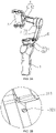
- a step portion 7 is formed at a joint between the second motor 31 and the third shaft arm 42 (as shown in FIG. 4A ); and when the handheld gimbal is switched to the storage state, the step portion 7 faces away from the sidewall 13 of the handle 1. If the step portion 7 faces toward the sidewall 13 of the handle 1 when the handheld gimbal is stored, the existence of the step portion 7 may cause a large gap between the third shaft arm 42 and the sidewall 13 of the handle 1. While when the handheld gimbal in this embodiment is stored, the step portion 7 faces away from the sidewall 13 of the handle 1, and this reduces the gap between the third shaft arm 42 and the sidewall 13 of the handle 1, so that the handheld gimbal becomes more compact in storage. Referring to FIG. 4A again, the step portion 7 in this embodiment is in an "L" shape.
- whether the second shaft arm 32 is folded along the rotatable connecting member 6 relative to the first shaft arm 22 may be controlled based on a manual control manner or an automatic control manner, so that the handheld gimbal can be switched between the use state and the storage state.
- a manual control manner a key trigger control or another automatic trigger manner may be selected.
- the holder 5 can still be used when the handheld gimbal is stored.
- the imaging lens when the handheld gimbal is stored, the imaging lens can still be used for photographing, and a difference thereof from use of the imaging lens for photographing when the handheld gimbal is in the use state lies in that when the imaging lens of the handheld gimbal in the storage state is used for photographing, a posture switch cannot be achieved for the imaging lens by means of the first motor 21 and the second motor 31; however, the third motor 41 may be controlled to perform a posture switching for the imaging lens.
- the size and shape of the imaging lens are not limited by limited space, and may be selected and changed based on the photographing needs of a user. For example, in one case, a circular imaging lens may be selected. In another case, a square imaging lens may be selected. Certainly in other cases, imaging lenses of other sizes or shapes may be selected, which is not limited herein.
- the photographing apparatus 100 may continue to be used for photographing, and the photographing apparatus 100 may be further operated. Moreover, the handheld gimbal carrying the photographing apparatus 100 may be stored.
- a difference between the use of the photographing apparatus 100 for photographing when the handheld gimbal is in the storage state and the use of the photographing apparatus 100 for photographing when the handheld gimbal is in the use state lies in that when the photographing apparatus 100 of the handheld gimbal in the storage state is used for photographing, a posture switch cannot be achieved for the photographing apparatus 100 by means of the first motor 21 and the second motor 31; however, the third motor 41 may be controlled to perform a posture switching for the photographing apparatus 100.
- the photographing apparatus 100 may be stored with the handheld gimbal together instead of being stored separately. This saves storage space, and is more advantageous for carrying the handheld gimbal by a user for outdoor use.
- the holder 5 is located on one side of the third motor 41 away from the sidewall 13 of the handle 1. This ensures that the holder 5 can still be used when the handheld gimbal is stored.
- the following describes in detail a positional relationship of the holder 5 when the handheld gimbal is stored in the case where the holder 5 includes the carrying part for fixing the photographing apparatus 100.
- a bearing structure for carrying a photographing apparatus is arranged between a shaft assembly and a handle, and the storage function can be finished only when the photographing apparatus is removed from the bearing structure; therefore, the use is inconvenient.
- the carrying part is located on one side of the third motor 41 away from the sidewall 13 of the handle 1.
- the handheld gimbal carrying the photographing apparatus can be stored, and can be used more conveniently.
- the photographing apparatus 100 can continue to be used for photographing; and the photographing apparatus 100 can be further operated to perform video playback or the like.
- a structure of the carrying part may be designed as needed.
- the carrying part is a clamping structure.
- an opening of the clamping structure faces away from the third motor 41. This arrangement of the opening of the clamping structure can ensure that when the handheld gimbal is stored, the photographing apparatus 100 can face outside. Hence, it would be convenient for a user to use the photographing apparatus 100.
- the clamping structure in this embodiment has a locked state and an unlocked state.
- the clamping structure can clamp and fix the photographing apparatus 100, and the third motor 41 can rotate around the third axis of rotation.
- the clamping structure is locked on the third shaft arm 42 to limit the rotation of the third motor 41.
- the clamping structure automatically switches to the locked state.
- the handheld gimbal is switched to the storage state, and the clamping structure is still in the unlocked state, a user needs to switch the clamping structure to the locked state manually.
- the clamping structure when the clamping structure is in the locked state, the clamping structure may be switched from the locked state to the unlocked state by way of an automatic unlocking (key/button unlocking) manner or a manual unlocking manner.
- a locking structure implemented by the clamping structure and the third shaft arm 42 may be a conventional structure, which will not be described in this embodiment.
- the structure of the carrying part is not limited to the design of the clamping structure, and may also be another structure.
- the rotatable connecting member 6 can easily rotates under an external force. Therefore, the handheld gimbal cannot be kept in the storage state, and this is disadvantageous for storing and carrying the handheld gimbal.
- a locking manner is used to keep the handheld gimbal in the storage state.
- a first slot 111 is provided on the top portion 11
- the first motor 21 is provided with a second slot 211
- a locking member 8 is disposed in the second slot 211
- a locking protrusion 221 is provided on the second shaft arm 32.
- the handheld gimbal when the first slot 111 is aligned with the second slot 211, it indicates that the handheld gimbal can be switched to the storage state, that is, the handheld gimbal can be switched from the use state to the storage state only when the first slot 111 is aligned with the second slot 211; if the first slot 111 is not aligned with the second slot 211, the handheld gimbal cannot be switched from the use state to the storage state.
- the second shaft arm 32 When the first slot 111 is aligned with the second slot 211, the second shaft arm 32 is triggered to rotate toward the first shaft arm 22 along the rotatable connecting member 6, so that the locking protrusion 221 enters the second slot 211; during the process in which the locking protrusion 221 enters into the second slot 211, the locking protrusion 221 may trigger the locking member 8 in the second slot 211 to move toward the first slot 111, so that a part of the locking member 8 enters the first slot 111 and engages with the first slot 111, as shown in FIG. 6A and FIG. 6B , so as to prevent the first shaft assembly 2 and the second shaft assembly 3 from rotating relative to the handle 1, and thus the handheld gimbal retains in the storage state.
- the engagement between the locking member 8 and the first slot 111 makes the first motor 21 unable to rotate relative to the handle 1, so that the first shaft assembly 2 is prevented from rotating relative to the handle 1.
- the second shaft arm 32 is fixed on the first motor 21, so that the second shaft assembly 3 is prevented from rotating relative to the handle 1.
- An interference fit may be selected for implementing the fixing between the locking member 8 and the first slot 111 and the fixing between the locking protrusion 221 and the second slot 211, or other manners may be selected for implementing the fixing.
- a stator of the first motor 21 may be fixedly connected to the top portion 11, and relative positions of the first slot 111 and the second slot 211 are always unchanged, that is, the first slot 111 is always aligned with the second slot 211.
- the rotor of the first motor 21 is fixedly connected to the top portion 11; the rotor of the first motor 21 is disposed in the second slot 211; and the locking protrusion 221 is disposed on the second shaft arm 32.
- a position of the second slot 211 relative to the first slot 111 changes, and the rotor of the first motor 21 can rotate relative to the handle 1 to align the first slot 111 with the first slot 111, as shown in FIG. 5A and FIG. 5B .
- the locking member 8 in this embodiment may be an elastic member, such as an elastic member made of an elastic material or an elastic member having a spring. Certainly, the locking member 8 may also be a non-elastic member.
- the handheld gimbal When the handheld gimbal is in the storage state, the handheld gimbal may also be controlled to switch from the storage state to the use state in a different manner.
- the user may manually operate (for example, push or pull) the second shaft arm 32 to rotate along the rotatable connecting member 6 relative to the first shaft arm 22, so that the second shaft arm 32 gradually moves away from the first motor 21.
- the locking protrusion 221 moves in a direction away from the second slot 211.
- the locking member 8 may move in a direction away from the first slot 111 under an elastic recovery force.
- the locking protrusion 221 completely detaches from the second slot 211
- the locking member 8 may be reset under the elastic recovery force, and thus is completely accommodated within the second slot 211. In this way, both the first motor 21 and the second shaft arm 32 may rotate relative to the handle 1, and the handheld gimbal is switched to the use state.
- an unlocking portion is provided on the sidewall 13 of the handle 1, and the unlocking portion can cooperate with the locking member 8.
- the locking member 8 When the unlocking portion is operated, the locking member 8 can be pushed by the unlocking portion to move in a direction away from the first slot 111 to detach from the first slot 111, and when the locking member 8 pushes the locking protrusion 221 out of the second slot 211, the handheld gimbal can switch from the storage state to the use state.
- the unlocking portion may be operated in a press manner, a pull manner, a push manner, or other operation manners.
- the unlocking portion may be an electronic unlocking structure, or may be a mechanical unlocking structure. Specifically, the type of the unlocking potion may be selected as needed.
- the second motor 31 may rotate to a preset position, which indicates that the handheld gimbal can be switched to the storage state, that is, when the second motor 31 rotates to the preset position, the handheld gimbal can be switched from the use state to the storage state. If the second motor 31 does not rotate to the preset position, that is, if the first shaft arm 22 and the second shaft arm 32 are folded, it is possible that the second motor 31 does not rotate to an appropriate position or that the second motor 31 and/or the third shaft assembly 4 cannot be folded in an appropriate position, making the handheld gimbal unable to switch from the use state to the storage state.
- the preset position is a limiting position of the second motor 31.
- the stator of the second motor 31 may be provided with a limiting protrusion 311 for limiting the rotation of a rotor of the second motor 31, and the limiting protrusion 311 is disposed near the locking protrusion 221.
- a user may need to control the second motor 31 to rotate to the position of the limiting protrusion 311.
- the preset position is not limited to this limiting position of the second motor 31 and may also be another rotation position of the second motor 31.
- a process of operating the handheld gimbal to switch from the use state to the storage state may include: controlling the first motor 21 to rotate relative to the handle 1 so that the first slot 111 is aligned with the second slot 211, controlling the second motor 31 to rotate to the limiting position, where these two steps may be performed simultaneously or sequentially; after controlling the first motor 21 to rotate relative to the handle 1 so that the first slot 111 is aligned with the second slot 211 and controlling the second motor 31 to rotate to the limiting position, operating the first shaft arm 22 and the second shaft arm 32 to fold these two shaft arms along the rotatable connecting member 6, so that the locking protrusion 221 enters the second slot 211; in the process in which the locking protrusion 221 enters the second slot 211, the locking protrusion 221 presses the locking member 8 in the second slot 211 downward, so that the locking member 8 moves toward the first slot 111, when a part of the locking member 8 enters the first slot 111 and engages with the first slot 111, the handheld gimbal switches
- the rotatable connecting member 6 may be a hinge member, or may be another type of rotatable member.
- the rotatable connecting member 6 may provide a supporting force; when the handheld gimbal is switched to the use state, the preset angle between the first shaft arm 22 and the second shaft arm 32 can be maintained by the supporting force from the rotatable connecting member 6. In this embodiment, the handheld gimbal may be kept in the use state by the supporting force from the rotatable connecting member 6.
- the rotatable connecting member 6 may include a damping structure; when the handheld gimbal is switched to the use state, the preset angle between the first shaft arm 22 and the second shaft arm 32 is maintained by a supporting force from the damping structure.
- the damping structure may be one of the following structures: a spring leaf, a cam, an elastic pin, and a torsional spring, but is not limited to the structures listed herein.
- the rotatable connecting member 6 may also include other structures to provide a supporting force, so that the handheld gimbal is kept in the use state.
- the rotatable connecting member 6 may include a rotation axle that cannot provide a supporting force.
- the rotation axle is not able to maintain the handheld gimbal in the use state; rather it needs to cooperate with another structure(s) in order to maintain the handheld gimbal in the use state.
- the first shaft arm 22 is provided with a locking mechanism
- the second shaft arm 32 is provided with a locking slot.
- the first shaft arm 22 is provided with a locking slot
- the second shaft arm 32 is provided with a locking mechanism.
- the locking mechanism engages with the locking slot to maintain the preset angle between the first shaft arm 22 and the second shaft arm 32, and thus maintain the handheld gimbal in the use state.
- the locking mechanism engages with locking slot for locking, so as to maintain the preset angle between the first shaft arm 22 and the second shaft arm 32, and thus maintain the handheld gimbal in the use state.
- a conventional locking and engaging manner may be selected herein.
- the locking mechanism may switch between an unlocked state and a locked state.
- the locking mechanism When the second shaft arm 32 rotates relative to the first shaft arm 22 along the rotation axle to the extent where the preset angle is formed between the first shaft arm 22 and the second shaft arm 32, the locking mechanism is triggered to enter the locked state; when the locking mechanism is in the unlocked state, the second shaft arm 32 may rotate relative to the first shaft arm 22 along the rotation axle.
- the locking mechanism automatically enters the locking slot to lock and engage with the locking slot.
- a user may manually operates the locking mechanism, so that the locking mechanism enters the locking slot to lock and engage with the locking slot.
- the first axis of rotation, the second axis of rotation and the third axis of rotation are orthogonal to each other.
- at least two of the first axis of rotation, the second axis of rotation and the third axis of rotation are oblique to each other.
- An intersection manner of the first axis of rotation, the second axis of rotation and the third axis of rotation may be selected as needed when the handheld gimbal is used.
- the first axis of rotation is a yaw axis
- the second axis of rotation is a pitch direction
- the third axis of rotation is a roll direction.
- the yaw axis is approximately parallel with a vertical direction.
- the yaw axis is parallel with the vertical direction.
- rotation directions of the first axis of rotation, the second axis of rotation and the third axis of rotation may also be in other manners.
- the first axis of rotation is the yaw axis
- the second axis of rotation is the roll axis
- the third axis of rotation is the pitch axis.
- an extension direction of the handle 1 (which may refer to a connection line from a center point of the top portion 11 of the handle 1 to a center point of the bottom portion 12, or may be parallel with this connection line) is oblique to the yaw axis.
- the holding direction of the handle 1 held by the user and the extension direction of the handle 1 are in the same direction when the handheld gimbal is in the use state, the holding direction is also oblique to the yaw axis. Therefore, the user can hold the handle 1 more easily and conveniently.
- the extension direction of the handle 1 is oblique to the yaw axis. This facilitates the user's holding, improves the user's experience of holding the handle 1 in the use state, and makes it more convenient for the user to use the handheld gimbal.
- an angle between the extension direction of the handle 1 and the yaw axis may be greater than or equal to 5° and less than or equal to 45°, for example, 5°, 10°, 15°, 20°, 30°, 40°, 45°, or other angles between 5° and 45°.
Applications Claiming Priority (1)
| Application Number | Priority Date | Filing Date | Title |
|---|---|---|---|
| PCT/CN2019/088667 WO2020237487A1 (zh) | 2019-05-27 | 2019-05-27 | 手持云台 |
Publications (1)
| Publication Number | Publication Date |
|---|---|
| EP3978792A1 true EP3978792A1 (en) | 2022-04-06 |
Family
ID=72433305
Family Applications (1)
| Application Number | Title | Priority Date | Filing Date |
|---|---|---|---|
| EP19930491.6A Withdrawn EP3978792A1 (en) | 2019-05-27 | 2019-05-27 | Handheld gimbal |
Country Status (4)
| Country | Link |
|---|---|
| US (1) | US11384900B2 (zh) |
| EP (1) | EP3978792A1 (zh) |
| CN (2) | CN111684196B (zh) |
| WO (1) | WO2020237487A1 (zh) |
Families Citing this family (9)
| Publication number | Priority date | Publication date | Assignee | Title |
|---|---|---|---|---|
| CN105937697B (zh) * | 2016-06-16 | 2019-04-23 | 广东思锐光学股份有限公司 | 一种手持稳定器 |
| USD914794S1 (en) * | 2019-04-12 | 2021-03-30 | SZ DJI Technology Co., Ltd. | Gimbal with handle |
| CN111684196B (zh) * | 2019-05-27 | 2021-12-21 | 深圳市大疆创新科技有限公司 | 手持云台 |
| USD967240S1 (en) * | 2020-08-19 | 2022-10-18 | SZ DJI Technology Co., Ltd. | Gimbal |
| USD974452S1 (en) * | 2020-09-16 | 2023-01-03 | SZ DJI Technology Co., Ltd. | Gimbal |
| EP4007866A4 (en) * | 2020-10-15 | 2022-06-08 | SZ DJI Technology Co., Ltd. | PROCEDURE FOR Gimbal CONTROL AND Gimbal |
| CN113124304B (zh) * | 2021-03-31 | 2022-05-03 | 桂林智神信息技术股份有限公司 | 一种带竖向减震机构的稳定器手持部及手持稳定器 |
| WO2022205091A1 (zh) * | 2021-03-31 | 2022-10-06 | 深圳市大疆创新科技有限公司 | 云台控制方法、云台和移动平台 |
| USD995614S1 (en) * | 2021-07-02 | 2023-08-15 | Winners' Sun Plastic & Electronic (Shenzhen) Co., Ltd. | Support stick |
Family Cites Families (12)
| Publication number | Priority date | Publication date | Assignee | Title |
|---|---|---|---|---|
| US9574706B2 (en) * | 2013-01-04 | 2017-02-21 | Garrett W. Brown | Folding image stabilizer |
| WO2016011159A1 (en) * | 2014-07-15 | 2016-01-21 | JIBO, Inc. | Apparatus and methods for providing a persistent companion device |
| KR20170099073A (ko) * | 2016-02-23 | 2017-08-31 | 김태완 | 3축 흔들림 보정장치가 구비된 영상촬영 짐벌기구 |
| CN205781893U (zh) * | 2016-05-24 | 2016-12-07 | 深圳市云之思科技有限公司 | 一种手持云台 |
| CN107856851A (zh) * | 2017-11-30 | 2018-03-30 | 广州市华科尔科技股份有限公司 | 一种紧凑型可折叠无人机 |
| CN208253098U (zh) * | 2018-05-16 | 2018-12-18 | 深圳市随拍科技有限公司 | 一种手持稳定器 |
| CN208503902U (zh) * | 2018-07-18 | 2019-02-15 | 深圳市大疆创新科技有限公司 | 一种手持云台 |
| CN208703455U (zh) * | 2018-08-24 | 2019-04-05 | 深圳市大疆创新科技有限公司 | 云台、手持云台和手持拍摄装置 |
| CN108980587A (zh) * | 2018-09-18 | 2018-12-11 | 智卓(深圳)电子科技有限公司 | 手持云台 |
| CN210050550U (zh) * | 2019-05-27 | 2020-02-11 | 深圳市大疆创新科技有限公司 | 手持云台 |
| CN111684196B (zh) * | 2019-05-27 | 2021-12-21 | 深圳市大疆创新科技有限公司 | 手持云台 |
| US20210258462A1 (en) * | 2019-12-23 | 2021-08-19 | Tim Goldburt | Device for supporting a smartphone or camera |
-
2019
- 2019-05-27 CN CN201980009612.8A patent/CN111684196B/zh active Active
- 2019-05-27 CN CN202111572150.6A patent/CN114278853A/zh not_active Withdrawn
- 2019-05-27 EP EP19930491.6A patent/EP3978792A1/en not_active Withdrawn
- 2019-05-27 WO PCT/CN2019/088667 patent/WO2020237487A1/zh unknown
-
2021
- 2021-01-07 US US17/143,641 patent/US11384900B2/en active Active
Also Published As
| Publication number | Publication date |
|---|---|
| US20210123564A1 (en) | 2021-04-29 |
| WO2020237487A1 (zh) | 2020-12-03 |
| CN111684196A (zh) | 2020-09-18 |
| CN114278853A (zh) | 2022-04-05 |
| CN111684196B (zh) | 2021-12-21 |
| US11384900B2 (en) | 2022-07-12 |
Similar Documents
| Publication | Publication Date | Title |
|---|---|---|
| US11384900B2 (en) | Handheld gimbal | |
| CN210050550U (zh) | 手持云台 | |
| US11675255B2 (en) | Holding mechanism for stabilizer and handheld stabilizer | |
| CN111758001B (zh) | 可折叠的手持云台 | |
| CN211046986U (zh) | 云台 | |
| CN111727340B (zh) | 可折叠的手持云台 | |
| CN111727341B (zh) | 可折叠的手持云台 | |
| CN110024364A (zh) | 云台拍摄器 | |
| CN210567422U (zh) | 手持云台 | |
| CN210485212U (zh) | 手持云台及拍摄设备 | |
| CN210687718U (zh) | 可折叠的手持云台 | |
| CN111699339B (zh) | 手持云台 | |
| CN211667425U (zh) | 云台 | |
| CN112105861B (zh) | 手持云台 | |
| JP7201274B2 (ja) | 収納ケース、雲台アセンブリ、及び雲台収納ケース | |
| CN109964174A (zh) | 云台拍摄器 | |
| CN210107006U (zh) | 可折叠的手持云台 | |
| CN210241138U (zh) | 手持云台 | |
| CN213333202U (zh) | 手持云台 | |
| CN210687621U (zh) | 可折叠的手持云台 | |
| CN213656275U (zh) | 可折叠手持云台 | |
| CN110024367B (zh) | 云台拍摄器 | |
| CN211976487U (zh) | 一种拍摄稳定器 | |
| CN217088024U (zh) | 一种便携式视频场景图像用处理装置 | |
| CN210319339U (zh) | 手持组件及应用其的自拍杆 |
Legal Events
| Date | Code | Title | Description |
|---|---|---|---|
| STAA | Information on the status of an ep patent application or granted ep patent |
Free format text: STATUS: THE INTERNATIONAL PUBLICATION HAS BEEN MADE |
|
| STAA | Information on the status of an ep patent application or granted ep patent |
Free format text: STATUS: THE INTERNATIONAL PUBLICATION HAS BEEN MADE |
|
| PUAI | Public reference made under article 153(3) epc to a published international application that has entered the european phase |
Free format text: ORIGINAL CODE: 0009012 |
|
| STAA | Information on the status of an ep patent application or granted ep patent |
Free format text: STATUS: REQUEST FOR EXAMINATION WAS MADE |
|
| 17P | Request for examination filed |
Effective date: 20210112 |
|
| AK | Designated contracting states |
Kind code of ref document: A1 Designated state(s): AL AT BE BG CH CY CZ DE DK EE ES FI FR GB GR HR HU IE IS IT LI LT LU LV MC MK MT NL NO PL PT RO RS SE SI SK SM TR |
|
| DAV | Request for validation of the european patent (deleted) | ||
| DAX | Request for extension of the european patent (deleted) | ||
| STAA | Information on the status of an ep patent application or granted ep patent |
Free format text: STATUS: THE APPLICATION HAS BEEN WITHDRAWN |
|
| 18W | Application withdrawn |
Effective date: 20220830 |