EP3977240B1 - Bewegungsbegrenzungsvorrichtung mit gemeinsamer basiselektrode - Google Patents
Bewegungsbegrenzungsvorrichtung mit gemeinsamer basiselektrode Download PDFInfo
- Publication number
- EP3977240B1 EP3977240B1 EP20724317.1A EP20724317A EP3977240B1 EP 3977240 B1 EP3977240 B1 EP 3977240B1 EP 20724317 A EP20724317 A EP 20724317A EP 3977240 B1 EP3977240 B1 EP 3977240B1
- Authority
- EP
- European Patent Office
- Prior art keywords
- electrode
- motion
- opposing
- base electrode
- base
- Prior art date
- Legal status (The legal status is an assumption and is not a legal conclusion. Google has not performed a legal analysis and makes no representation as to the accuracy of the status listed.)
- Active
Links
Images


Classifications
-
- G—PHYSICS
- G06—COMPUTING OR CALCULATING; COUNTING
- G06F—ELECTRIC DIGITAL DATA PROCESSING
- G06F3/00—Input arrangements for transferring data to be processed into a form capable of being handled by the computer; Output arrangements for transferring data from processing unit to output unit, e.g. interface arrangements
- G06F3/01—Input arrangements or combined input and output arrangements for interaction between user and computer
- G06F3/016—Input arrangements with force or tactile feedback as computer generated output to the user
-
- G—PHYSICS
- G06—COMPUTING OR CALCULATING; COUNTING
- G06F—ELECTRIC DIGITAL DATA PROCESSING
- G06F3/00—Input arrangements for transferring data to be processed into a form capable of being handled by the computer; Output arrangements for transferring data from processing unit to output unit, e.g. interface arrangements
- G06F3/01—Input arrangements or combined input and output arrangements for interaction between user and computer
- G06F3/011—Arrangements for interaction with the human body, e.g. for user immersion in virtual reality
-
- G—PHYSICS
- G06—COMPUTING OR CALCULATING; COUNTING
- G06F—ELECTRIC DIGITAL DATA PROCESSING
- G06F3/00—Input arrangements for transferring data to be processed into a form capable of being handled by the computer; Output arrangements for transferring data from processing unit to output unit, e.g. interface arrangements
- G06F3/01—Input arrangements or combined input and output arrangements for interaction between user and computer
- G06F3/011—Arrangements for interaction with the human body, e.g. for user immersion in virtual reality
- G06F3/014—Hand-worn input/output arrangements, e.g. data gloves
-
- H—ELECTRICITY
- H02—GENERATION; CONVERSION OR DISTRIBUTION OF ELECTRIC POWER
- H02N—ELECTRIC MACHINES NOT OTHERWISE PROVIDED FOR
- H02N13/00—Clutches or holding devices using electrostatic attraction, e.g. using Johnson-Rahbek effect
Definitions
- Virtual reality display systems immerse a user in virtual imagery occupying an entire field of view.
- Augmented reality or mixed reality display systems display virtual objects superimposed with real-world backgrounds, such as via a see-through display. In either case, visual and auditory aspects of a virtual experience may be represented in a lifelike manner.
- US2018143687A1 relates to an electrostatic slide clutch comprising a first electrode, a second electrode oriented parallel to first electrode, an electrically insulating structure disposed on the first electrode on a face of the first electrode opposing the second electrode, and a controller electrically coupled to the first electrode and to the second electrode and configured to apply a variable voltage between the first and second electrodes, to influence a normal force between the first and second electrodes.
- US2013010398A1 relates to an electro adhesive device with an outer surface adapted to interface with a surface of a foreign substrate, a plurality of electrodes, and a semiconductive insulation material disposed adjacent to at least one of the electrodes.
- Each electrode has a respective conductive volume and is configured to apply a voltage at a respective location of the outer surface, and the difference in voltage between applied voltages includes an electrostatic adhesion voltage that produces an electro-static force between the device and the substrate that is suitable to maintain a current position of the device relative to the substrate.
- the insulation material can be polyurethane or any other suitable material having a resistance of about 109 to 1012 ohms*m. The insulation material effectively operates to expand the conductive volume of the electrodes when they are actuated.
- Examples are disclosed that relate to electrostatic clutching mechanisms that may be used for tactile feedback.
- a motion-restricting apparatus comprising a wearable base, and an electrostatic clutching mechanism coupled to the base, the electrostatic clutching mechanism comprising a base electrode, a plurality of individually-controllable opposing electrodes arranged at different locations across the base electrode and overlapping the base electrode, and one or more electrically insulating structures configured to electrically insulate the base electrode from the plurality of opposing electrodes.
- the motion-restricting apparatus further comprises a controller electrically coupled to the base electrode and to each of the opposing electrodes and configured to individually control a voltage applied to each opposing electrode relative to a voltage of the base electrode to control an electrostatic force between the base electrode and each opposing electrode.
- FIG. 1 shows an electrostatic clutch 100 that may be incorporated in a wearable glove structure.
- Electrostatic clutch 100 includes two multi-layer electrodes 102, 104, such that an applied voltage between the electrodes exerts a resistive force between the two electrodes to selectively control a sliding motion of the electrodes relative to one another.
- the depicted clutch 100 is not able to independently control restrictive forces for more than one finger.
- multiple instances of electrostatic clutch 100 may be arranged in a side-by-side manner to provide independently controllable clutching for more than one finger.
- a voltage used to actuate the clutch may be dependent upon a surface area of a clutch
- relatively wider electrodes may allow the use of lower voltages. Due to the electrode width, a housing 106 that contains the electrodes may be too large to allow side-by-side clutches to be positioned in desired locations with respect to each finger (e.g. along an axis of each finger).
- examples relate to an electrostatic clutch arrangement that includes multiple independently controllable electrodes arranged in a compact configuration.
- the disclosed examples utilize an electrode arrangement in which a common base electrode is used for a plurality of individually controllable opposing electrodes.
- the common base electrode and plurality of individually controllable opposing electrodes may be housed within a common housing, thereby allowing multiple individually controllable electrodes to be positioned side-by-side in locations that align with the axes of corresponding fingers, in example implementations involving a wearable glove.
- a wearable base supporting such an electrostatic clutch arrangement may be worn alternatively or additionally on the leg, shoulder, neck, or other body part in some examples.
- an electrostatic clutch arrangement may be used in other electromechanical applications.
- the clutch may be used to provide positive braking for a servomechanical device (e.g., a robotic, soft robotic, prosthetic, and/or ball-joint).
- FIG. 2 schematically shows an example wearable glove 200 coupled to a motion restricting apparatus 202 having an electrostatic clutching mechanism including a common base electrode 204 and a plurality of independently-controllable opposing electrodes 206.
- One opposing electrode is provided for each finger of the glove 200, including the thumb.
- the base electrode 204 is coupled to the back of the glove 200, while each opposing electrode is coupled to a respective finger of the glove.
- each electrode may comprise multiple electrode layers in some examples, which may help to increase a surface area of each electrode for a given electrode width relative to single-layer electrodes.
- the layers of the base electrode may be interleaved with the layers of each opposing electrode.
- each electrode may be coated with an electrically insulating (dielectric) material to electrically insulate the opposing electrodes from the base electrode.
- dielectric electrically insulating
- a controller 208 is electrically coupled to the base electrode 204 and each of the opposing electrodes 206 to control the voltages applied to each of the base electrode 204 and the opposing electrodes 206.
- an alternating voltage of suitable frequency may be used to facilitate dynamically changing the force applied, as charge may be added to or removed from electrodes by varying a duty cycle, type of waveform, and/or amplitude of the alternating voltage.
- controller 208 may be communicatively coupled to a computing system, such as a display system, so that actuation of the clutching mechanism is triggered by a detected intersection of a user's hand with a displayed virtual object (e.g. as detected by image sensors, worn and/or stationary, in a use environment).
- FIG. 3 illustrates an example operation of a motion-restricting apparatus 300 having a base electrode 302 and independently-controllable opposing electrodes 304, 306.
- a voltage is applied to opposing electrode 304 of the middle finger relative to base electrode 302 to bias the opposing electrode 304 relative to the base electrode, thereby restricting motion of opposing electrode 304 relative to base electrode 302, while no bias voltage is applied to opposing electrode 306 of the index finger, allowing opposing electrode 306 to slide relative to base electrode 302.
- each electrode may comprise multiple electrode layers.
- FIG. 4 shows a sectional side view depicting example electrode layers of base electrode 302 and opposing electrode 304, 306.
- each electrode has seven electrode layers, forming an interleaving stack of 14 total layers.
- Each electrode layer includes an electrical conductor coated with a dielectric material.
- the electrode layers may be individually addressable by six output pins (one pin for each finger, and one for the common base) of the controller, rather than ten pins in arrangements where separate electrode pairs are used instead of a common base electrode. It will be understood that pins may provide an output to a suitable signal generator/amplifier circuit for generating a voltage (DC or AC) to apply to each electrode.
- each electrode layer may comprise a flexible polymer substrate coated with a suitable electrical conductor (e.g. a thin metal film, such as copper or aluminum), and overcoated with a dielectric material.
- each layer may comprise a conductive core material (e.g. a conductive metal strip, conductive fabric strip, conductive polymer strip, etc.), rather than a conductive thin film formed on a substrate.
- the dielectric material may be selected to exhibit a high dielectric strength in order to support a large electric field without dielectric breakdown, and a high dielectric constant to achieve a higher electrostatic force at a given voltage.
- the dielectric material may comprise a homogeneous thin film, such as a polymer of suitable dielectric constant and dielectric strength.
- an electrically insulating structure may comprise a composite material, e.g. a ceramic compound (e.g. barium titanate) contained within a polymer matrix.
- each electrode layer may be coated on a single side with a conductor and dielectric layer, or on both sides.
- FIG. 5 shows a first example in which a hole 502 is formed through the layers of an electrode, such that a pin can be used to hold the electrode layers in position relative to one another.
- FIG. 6 shows a side sectional view of the electrode 500, and illustrates each electrode layer as comprising a conductive core 602 coated on both sides with a dielectric material 604.
- the core may be formed from a solid conductor, or from a multilayer structure, such as copper or aluminum deposited (e.g. by sputtering, evaporation, etc.) on a polymer core (e.g. polyethylene terephthalate, for example).
- the dielectric layers are adhered together with a conductive polymer adhesive 606 applied within hole 502, such as a silver epoxy or other suitable material.
- Conductive polymer adhesive 606 adheres the electrode stack together and also electrically connects the layers so that the layers form a common conductor.
- FIGS. 7 and 8 show another example structure to mechanically and electrically connect a plurality of electrode layers.
- the electrode layers 700 are crimped at an end via a conductive sheet 702 having a zig-zag shape.
- the conductive sheet 702 may be formed form copper. In other examples, other suitable conductive materials may be used.
- the electrode may be assembled by placing individual electrode layers between the layers of the metal sheet, and then clamping the metal sheet to crimp the layers together, thereby forming both the mechanical and electrical connections in a same step.
- FIGS. 9 and 10 show an electrode 900 comprising an electrically conductive tape 902 between each electrode layer and the metal sheet 904 to adhere the metal sheet 904 to the electrode layers.
- the use of such an adhesive also may help to keep the metal sheet in place during construction of the electrode stack.
- FIG. 11 shows a partial, exploded view of a motion-restricting apparatus 1100 coupled to a glove 1102.
- Motion-restricting apparatus 1100 includes an electrostatic clutching mechanism 1104 that includes a base electrode 1106, and opposing electrodes 1108 and 1110 for the middle and index fingers respectively. In other examples, additional opposing electrodes may also be included, e.g. one for every finger, including the thumb.
- Motion-restricting apparatus 1100 includes a housing 1112 that is coupled to glove 1102 and configured to house base electrode 1106 and at least a portion of each of opposing electrodes 1108, 1110.
- a top cover 1114 (shown here detached) is configured to cover housing 1112. Inside housing 1112, fastening structures 1116, such as via snap interfaces 1118, may be used to fasten top cover 1114.
- Motion-restricting apparatus 1100 further includes dividers 1120 configured to maintain spacing between electrodes 1108 and 1110. As shown by way of example, one or more dividers 1120 may be arranged between electrodes 1108 and 1110, to ensure that the electrodes remain separate when sliding back and forth. Further, dividers 1120 may act as support to add more height to the housing structure and top cover 1114. Such additional clearance in z-height may help contribute to the flexibility of motion-restricting apparatus 1100.
- Motion-restricting apparatus 1100 further may include pivots 1122 disposed at the end of the electrodes 1108, 1110 that attach the ends of the electrodes 1108, 1110 to a Y-shaped force transmitter 1124 that transfers force arising from a finger flexing against an actuated clutch to a haptic output located at a pad of a fingertip to provide a sensation of touch.
- pivot structures 1122 may allow fingers to change angle with respect to the hand without putting undue lateral strain on the electrodes 1108, 1110.
- an electrode configuration for the thumb may differ compared to the electrode configurations for the other fingers due to the opposing position of the human thumb relative to the other fingers.
- the electrode for the thumb may include one or more pivots configured to allow angular/rotational motion of the thumb.
- additional dividers, walls, or other internal components and structures may help to guide an electrode for a thumb clutch within a housing.
- FIG. 12 shows a method 1200 of controlling a motion-restricting apparatus having an electrostatic clutching mechanism comprising a common base electrode and a plurality of opposing clutching electrodes.
- Method 1200 includes, at 1202, applying a first voltage to a base electrode of the electrostatic clutching mechanism.
- method 1200 includes, at 1204 applying the first voltage to a first opposing electrode to allow motion of the first opposing electrode relative to the base electrode.
- Method 1200 further includes, at 1206, while applying the first voltage to the first opposing electrode, applying a second voltage to a second opposing electrode to restrict motion of the second opposing electrode relative to the base electrode.
- method 1208 further may include, at 1208, individually controlling the voltages of three or more individually-controllable opposing electrodes relative to a voltage of the base electrode.
- applying a voltage may include applying an AC voltage, which may allow a clutching force to be varied by varying a duty cycle, type of waveform, and/or amplitude of the AC voltage applied to the electrode.
- the methods and processes described herein may be tied to a computing system of one or more computing devices.
- such methods and processes may be implemented as a computer-application program or service, an application-programming interface (API), a library, and/or other computer-program product.
- API application-programming interface
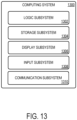
- FIG. 13 schematically shows a non-limiting embodiment of a computing system 1300 that can enact one or more of the methods and processes described above.
- Computing system 1300 is shown in simplified form.
- Computing system 1300 may take the form of one or more personal computers, server computers, tablet computers, home-entertainment computers, network computing devices, gaming devices, mobile computing devices, mobile communication devices (e.g., smart phone), and/or other computing devices, such as controller 208.
- Computing system 1300 includes a logic subsystem 1302 and a storage subsystem 1304.
- Computing system 1300 may optionally include a display subsystem 1306, input subsystem 1308, communication subsystem 1310, and/or other components not shown in FIG. 13 .
- Logic subsystem 1302 includes one or more physical devices configured to execute instructions.
- logic subsystem 1302 may be configured to execute instructions that are part of one or more applications, services, programs, routines, libraries, objects, components, data structures, or other logical constructs. Such instructions may be implemented to perform a task, implement a data type, transform the state of one or more components, achieve a technical effect, or otherwise arrive at a desired result.
- Logic subsystem 1302 may include one or more processors configured to execute software instructions. Additionally or alternatively, logic subsystem 1302 may include one or more hardware or firmware logic machines configured to execute hardware or firmware instructions. Processors of logic subsystem 1302 may be single-core or multicore, and the instructions executed thereon may be configured for sequential, parallel, and/or distributed processing. Individual components of logic subsystem 1302 optionally may be distributed among two or more separate devices, which may be remotely located and/or configured for coordinated processing. Aspects of logic subsystem 1302 may be virtualized and executed by remotely accessible, networked computing devices configured in a cloud-computing configuration.
- Storage subsystem 1304 includes one or more physical devices configured to hold instructions executable by the logic machine to implement the methods and processes described herein. When such methods and processes are implemented, the state of storage subsystem 1304 may be transformed-e.g., to hold different data.
- Storage subsystem 1304 may include removable and/or built-in devices.
- Storage subsystem 1304 may include optical memory (e.g., CD, DVD, HD-DVD, Blu-Ray Disc, etc.), semiconductor memory (e.g., RAM, EPROM, EEPROM, etc.), and/or magnetic memory (e.g., hard-disk drive, floppy-disk drive, tape drive, MRAM, etc.), among others.
- Storage subsystem 1304 may include volatile, nonvolatile, dynamic, static, read/write, read-only, random-access, sequential-access, location-addressable, file-addressable, and/or content-addressable devices.
- storage subsystem 1304 includes one or more physical devices.
- aspects of the instructions described herein alternatively may be propagated by a communication medium (e.g., an electromagnetic signal, an optical signal, etc.) that is not held by a physical device for a finite duration.
- a communication medium e.g., an electromagnetic signal, an optical signal, etc.
- logic subsystem 1302 and storage subsystem 1304 may be integrated together into one or more hardware-logic components.
- Such hardware-logic components may include field-programmable gate arrays (FPGAs), program- and application-specific integrated circuits (PASIC / ASICs), program- and application-specific standard products (PSSP / ASSPs), system-on-a-chip (SOC), and complex programmable logic devices (CPLDs), for example.
- FPGAs field-programmable gate arrays
- PASIC / ASICs program- and application-specific integrated circuits
- PSSP / ASSPs program- and application-specific standard products
- SOC system-on-a-chip
- CPLDs complex programmable logic devices
- display subsystem 1306 may be used to present a visual representation of data held by storage subsystem 1304.
- This visual representation may take the form of a graphical user interface (GUI).
- GUI graphical user interface
- Display subsystem 1306 may include one or more display devices utilizing virtually any type of technology. Such display devices may be combined with logic subsystem 1302 and/or storage subsystem 1304 in a shared enclosure, or such display devices may be peripheral display devices.
- input subsystem 1308 may comprise or interface with one or more user-input devices such as a keyboard, mouse, touch screen, or game controller.
- the input subsystem may comprise or interface with selected natural user input (NUI) componentry.
- NUI natural user input
- Such componentry may be integrated or peripheral, and the transduction and/or processing of input actions may be handled on- or off-board.
- NUI componentry may include a microphone for speech and/or voice recognition; an infrared, color, stereoscopic, and/or depth camera for machine vision and/or gesture recognition; a head tracker, eye tracker, accelerometer, and/or gyroscope for motion detection and/or intent recognition; as well as electric-field sensing componentry for assessing brain activity.
- communication subsystem 1310 may be configured to communicatively couple computing system 1300 with one or more other computing devices.
- Communication subsystem 1310 may include wired and/or wireless communication devices compatible with one or more different communication protocols.
- the communication subsystem may be configured for communication via a wireless telephone network, or a wired or wireless local- or wide-area network.
- the communication subsystem may allow computing system 1300 to send and/or receive messages to and/or from other devices via a network such as the Internet.
- a motion-restricting apparatus comprising a wearable base, and an electrostatic clutching mechanism coupled to the base, the electrostatic clutching mechanism comprising a base electrode, a plurality of individually-controllable opposing electrodes arranged at different locations across the base electrode and overlapping the base electrode, one or more electrically insulating structures configured to electrically insulate the base electrode from the plurality of opposing electrodes, and a controller electrically coupled to the base electrode and to each of the opposing electrodes and configured to individually control a voltage applied to each opposing electrode relative to a voltage of the base electrode to control an electrostatic force between the base electrode and each opposing electrode.
- the wearable base may additionally or alternatively include a glove, and the plurality of individually-controllable opposing electrodes may additionally or alternatively be associated with fingers of the glove.
- the motion-restricting apparatus may additionally or alternatively include a housing coupled to the base, wherein the base electrode and at least a portion of each opposing electrode is located within the housing. One of the opposing electrodes may additionally or alternatively be associated with a thumb of the glove.
- the motion-restricting apparatus may additionally or alternatively include one or more dividers arranged within the housing to maintain spacing between the opposing electrodes.
- the housing may additionally or alternatively include a top cover covering the base electrode, and the top cover may additionally or alternatively be configured to flex with motion of a body part on which the motion-restricting apparatus is worn.
- the top cover may additionally or alternatively be configured to attach to the housing via one or more snap interfaces.
- Each opposing electrode may additionally or alternatively include a plurality of electrode layers at least partially interleaved with a plurality of electrode layers of the base electrode.
- the electrically insulating structures may additionally or alternatively be conductively connected by a conductive adhesive.
- the plurality of electrodes may additionally or alternatively be connected via a conductive crimp.
- the motion-restricting apparatus may additionally or alternatively include conductive tape adhering the conductive crimp to the plurality of electrode layers.
- the base electrode and the opposing electrodes may additionally or alternatively be flexible.
- Another example provides a method of operating a motion-restricting apparatus comprising a base electrode and a plurality of individually-controllable opposing electrodes, the method comprising, applying a first voltage to a first opposing electrode to allow motion of the first opposing electrode relative to the base electrode, and while applying the first voltage to the first opposing electrode, applying a second voltage to a second opposing electrode to restrict motion of the second opposing electrode relative to the base electrode.
- the method may additionally or alternatively include individually controlling voltages of three or more of the plurality of individually-controllable opposing electrodes relative to a voltage of the base electrode.
- a motion-restricting apparatus comprising a glove, and an electrostatic clutching mechanism coupled to the glove, the electrostatic clutching mechanism comprising a base electrode disposed on a back portion of the glove, a plurality of individually-controllable opposing electrodes associated with fingers of the glove, each of the opposing electrodes arranged to overlap the base electrode, and each opposing electrode comprising a plurality of electrode layers at least partially interleaved with a plurality of electrode layers of the base electrode, one or more electrically insulating structures configured to electrically insulate the base electrode from the plurality of opposing electrodes, and a controller electrically coupled to the base electrode and to each of the opposing electrodes and configured to individually control a voltage applied to each opposing electrode relative to a voltage of the base electrode to control an electrostatic force between the base electrode and each opposing electrode.
- the motion-restricting apparatus may additionally or alternatively include a housing coupled to the glove, wherein the base electrode and at least a portion of each individually-controllable opposing electrode may additionally or alternatively be located within the housing.
- the motion-restricting apparatus may additionally or alternatively include a plurality of dividers arranged within the housing to maintain spacing between the opposing electrodes.
- the housing may additionally or alternatively include a top cover covering the base electrode, and wherein the top cover is configured to flex with motion of a body part on which the motion-restricting apparatus is worn.
- the top cover may additionally or alternatively be configured to attach to the housing via one or more snap interfaces.
- the base electrode and the opposing electrodes may additionally or alternatively be flexible.
Landscapes
- Engineering & Computer Science (AREA)
- General Engineering & Computer Science (AREA)
- Theoretical Computer Science (AREA)
- Human Computer Interaction (AREA)
- Physics & Mathematics (AREA)
- General Physics & Mathematics (AREA)
- User Interface Of Digital Computer (AREA)
Claims (12)
- Am Körper getragene Bewegungsbegrenzungsvorrichtung (202), die Folgendes umfasst:eine tragbare Basis;ein Gehäuse (1112), das mit der Basis gekoppelt ist; undeinen elektrostatischen Kupplungsmechanismus, der mit der Basis gekoppelt ist, wobei der elektrostatische Kupplungsmechanismus Folgendes umfassteine Basiselektrode (204; 1106);eine Vielzahl von individuell steuerbaren Gegenelektroden (206), die an verschiedenen Stellen über der Basiselektrode angeordnet sind und die Basiselektrode überlappen, wobei die Basiselektrode und mindestens ein Abschnitt jeder Gegenelektrode innerhalb des Gehäuses positioniert ist;ein oder mehrere Teiler (1120), die so konfiguriert sind, dass sie einen Abstand zwischen den Gegenelektroden aufrechterhalten, wobei der eine oder die mehreren Teiler innerhalb des Gehäuses angeordnet sind;eine oder mehrere elektrisch isolierende Strukturen, die so konfiguriert sind, dass sie die Basiselektrode von der Vielzahl der Gegenelektroden elektrisch isolieren; undeine Steuerung (208), die elektrisch mit der Basiselektrode und jeder der Gegenelektroden gekoppelt und so konfiguriert ist, dass sie individuell eine an jede Gegenelektrode angelegte Spannung relativ zu einer Spannung der Basiselektrode steuert, um eine elektrostatische Kraft zwischen der Basiselektrode und jeder Gegenelektrode zu steuern.
- Bewegungsbegrenzungsvorrichtung nach Anspruch 1, wobei die tragbare Basis einen Handschuh umfasst und wobei die Vielzahl von individuell steuerbaren Gegenelektroden den Fingern des Handschuhs zugeordnet ist.
- Bewegungsbegrenzungsvorrichtung nach Anspruch 2, wobei eine der Gegenelektroden einem Daumen des Handschuhs zugeordnet ist.
- Bewegungsbegrenzungsvorrichtung nach Anspruch 1, wobei das Gehäuse ferner eine obere Abdeckung (1114) umfasst, die die Basiselektrode bedeckt, und wobei die obere Abdeckung so konfiguriert ist, dass sie sich bei der Bewegung eines Körperteils, an dem die Bewegungsbegrenzungsvorrichtung getragen wird, biegt.
- Bewegungsbegrenzungsvorrichtung nach Anspruch 4, wobei die obere Abdeckung so konfiguriert ist, dass sie über eine oder mehrere Schnappschnittstellen (1118) an dem Gehäuse befestigt wird.
- Bewegungsbegrenzungsvorrichtung nach Anspruch 1, wobei jede Gegenelektrode (500) eine Vielzahl von Elektrodenschichten umfasst, die mindestens teilweise mit einer Vielzahl von Elektrodenschichten der Basiselektrode verschachtelt ist.
- Bewegungsbegrenzungsvorrichtung nach Anspruch 6, wobei die elektrisch isolierenden Strukturen durch einen leitfähigen Klebstoff (606) leitend verbunden sind.
- Bewegungsbegrenzungsvorrichtung nach Anspruch 6, wobei die Vielzahl der Elektroden über eine leitfähige Quetschverbindung (702) verbunden ist.
- Bewegungsbegrenzungsvorrichtung nach Anspruch 8, ferner umfassend ein leitfähiges Band (902), das die leitfähige Quetschverbindung (904) mit der Vielzahl der Elektrodenschichten verklebt.
- Bewegungsbegrenzungsvorrichtung nach Anspruch 1, wobei die Basiselektrode und die Gegenelektroden flexibel sind.
- Verfahren zum Betreiben der am Körper getragenen Bewegungsbegrenzungsvorrichtung nach Anspruch 1, wobei das Verfahren Folgendes umfasst:Anlegen (1202) einer ersten Spannung an eine erste Gegenelektrode, um die Bewegung der ersten Gegenelektrode relativ zu der Basiselektrode zu ermöglichen, undwährend des Anlegens der ersten Spannung an die erste Gegenelektrode, Anlegen einer zweiten Spannung (1206) an eine zweite Gegenelektrode, um die Bewegung der zweiten Gegenelektrode relativ zu der Basiselektrode zu begrenzen,wobei die erste und die zweite Gegenelektrode durch einen Abstand isoliert sind, der zwischen der ersten und der zweiten Gegenelektrode durch einen oder mehrere innerhalb des Gehäuses angeordnete Teiler (1120) aufrechterhalten wird.
- Verfahren nach Anspruch 11, ferner umfassend individuelles Steuern (1208) der Spannungen von drei oder mehr der Vielzahl von individuell steuerbaren Gegenelektroden relativ zu einer Spannung der Basiselektrode.
Applications Claiming Priority (2)
| Application Number | Priority Date | Filing Date | Title |
|---|---|---|---|
| US16/422,801 US11054905B2 (en) | 2019-05-24 | 2019-05-24 | Motion-restricting apparatus with common base electrode |
| PCT/US2020/028381 WO2020242620A1 (en) | 2019-05-24 | 2020-04-16 | Motion-restricting apparatus with common base electrode |
Publications (2)
| Publication Number | Publication Date |
|---|---|
| EP3977240A1 EP3977240A1 (de) | 2022-04-06 |
| EP3977240B1 true EP3977240B1 (de) | 2024-11-06 |
Family
ID=70554230
Family Applications (1)
| Application Number | Title | Priority Date | Filing Date |
|---|---|---|---|
| EP20724317.1A Active EP3977240B1 (de) | 2019-05-24 | 2020-04-16 | Bewegungsbegrenzungsvorrichtung mit gemeinsamer basiselektrode |
Country Status (3)
| Country | Link |
|---|---|
| US (1) | US11054905B2 (de) |
| EP (1) | EP3977240B1 (de) |
| WO (1) | WO2020242620A1 (de) |
Families Citing this family (12)
| Publication number | Priority date | Publication date | Assignee | Title |
|---|---|---|---|---|
| US11023047B2 (en) | 2018-05-01 | 2021-06-01 | Microsoft Technology Licensing, Llc | Electrostatic slide clutch with bidirectional drive circuit |
| US11061476B2 (en) | 2019-05-24 | 2021-07-13 | Microsoft Technology Licensing, Llc | Haptic feedback apparatus |
| JP2021116491A (ja) * | 2020-01-27 | 2021-08-10 | 富士フイルムビジネスイノベーション株式会社 | 触覚提示装置 |
| EP4272304A4 (de) * | 2020-12-30 | 2025-04-09 | NIKE Innovate C.V. | Elektroadhäsive aktuatoren mit verlängerter lebensdauer |
| JP2024509493A (ja) | 2020-12-30 | 2024-03-04 | ナイキ イノベイト シーブイ | 衣料品における静電型接着システムの隔離 |
| KR20230125799A (ko) * | 2020-12-30 | 2023-08-29 | 나이키 이노베이트 씨.브이. | 전기접착 액추에이터에서의 벌크 전하 최소화 |
| CN112773666B (zh) * | 2021-01-22 | 2025-09-26 | 上海司羿智能科技有限公司 | 手部运动检测装置及控制方法、康复装置和自主控制系统 |
| EP4323153B1 (de) | 2021-04-16 | 2025-12-24 | Black & Decker Inc. | Elektrostatische kupplung für ein kraftwerkzeug |
| WO2022241326A1 (en) * | 2021-05-14 | 2022-11-17 | Estat Actuation, Inc. | Electroadhesive clutch for universal load directions transmisison |
| CA3230947A1 (en) * | 2021-09-08 | 2023-03-16 | Patrick McKinley JARVIS | Wearable robot data collection system with human-machine operation interface |
| JP7661900B2 (ja) * | 2022-01-17 | 2025-04-15 | トヨタ自動車株式会社 | 関節機構 |
| WO2024144946A2 (en) * | 2022-11-17 | 2024-07-04 | Estat Actuation, Inc. | Electrically controllable device for preventing fatigue and acute injury |
Family Cites Families (170)
| Publication number | Priority date | Publication date | Assignee | Title |
|---|---|---|---|---|
| US2897425A (en) | 1958-10-21 | 1959-07-28 | Robert W Waring | Method of and apparatus for producing electrostatic force |
| US4753442A (en) * | 1987-04-20 | 1988-06-28 | Bland Clyde S W | Baseball glove with automatic ball return device |
| US4987332A (en) | 1988-09-30 | 1991-01-22 | Pentel Kabushiki Kaisha | Robot hand for electrostatically applying thin workpiece to mold |
| US5173834A (en) | 1989-06-02 | 1992-12-22 | Roland Dg Corporation | Electrostatic attraction apparatus |
| US5631861A (en) | 1990-02-02 | 1997-05-20 | Virtual Technologies, Inc. | Force feedback and texture simulating interface device |
| US5184319A (en) | 1990-02-02 | 1993-02-02 | Kramer James F | Force feedback and textures simulating interface device |
| JPH06126661A (ja) | 1992-10-12 | 1994-05-10 | Mitsubishi Cable Ind Ltd | マイクロ部品ハンドリング装置 |
| US5429140A (en) * | 1993-06-04 | 1995-07-04 | Greenleaf Medical Systems, Inc. | Integrated virtual reality rehabilitation system |
| US5516249A (en) * | 1994-05-10 | 1996-05-14 | Technical Research Associates, Inc. | Exoskeleton with kinesthetic feedback and robotic control |
| IT1281584B1 (it) | 1996-01-02 | 1998-02-20 | Benito Ferrati | Apparecchiatura ortopedica per la deambulazione e riabilitazione di persone motu-lese con l'impiego di unita' elettroniche e di realta' |
| US6128004A (en) | 1996-03-29 | 2000-10-03 | Fakespace, Inc. | Virtual reality glove system with fabric conductors |
| US6809462B2 (en) | 2000-04-05 | 2004-10-26 | Sri International | Electroactive polymer sensors |
| US6524681B1 (en) | 1997-04-08 | 2003-02-25 | 3M Innovative Properties Company | Patterned surface friction materials, clutch plate members and methods of making and using same |
| US6042555A (en) | 1997-05-12 | 2000-03-28 | Virtual Technologies, Inc. | Force-feedback interface device for the hand |
| AU7482298A (en) | 1997-05-12 | 1998-12-08 | Virtual Technologies, Inc. | Force-feedback interface device for the hand |
| US7166953B2 (en) | 2001-03-02 | 2007-01-23 | Jon Heim | Electroactive polymer rotary clutch motors |
| SG103371A1 (en) | 2001-12-28 | 2004-04-29 | Matsushita Electric Works Ltd | Wearable human motion applicator |
| AU2002951193A0 (en) | 2002-09-04 | 2002-09-19 | Northern Sydney Area Health Service | Movement faciliatation device |
| US20040084261A1 (en) | 2002-11-01 | 2004-05-06 | Performance Friction Corporation | Brake rotor with a surface having a plurality of indentations formed therein |
| US6966882B2 (en) | 2002-11-25 | 2005-11-22 | Tibion Corporation | Active muscle assistance device and method |
| JP2004213350A (ja) * | 2002-12-27 | 2004-07-29 | Seiko Epson Corp | 力覚提示装置及び画像補正方法 |
| US6790308B2 (en) | 2003-01-03 | 2004-09-14 | Borgwarner Inc. | Method and apparatus for making clutch plate with multi segment friction material |
| JP4644830B2 (ja) | 2003-03-26 | 2011-03-09 | 独立行政法人理化学研究所 | 誘電体絶縁薄膜の製造方法 |
| US7046151B2 (en) | 2003-07-14 | 2006-05-16 | Michael J. Dundon | Interactive body suit and interactive limb covers |
| JP2005227111A (ja) | 2004-02-12 | 2005-08-25 | Masaru Hakoda | 織物状電極と物質フィルター装置 |
| US7598651B2 (en) | 2004-03-12 | 2009-10-06 | Sri International | Mechanical meta-materials |
| US7365463B2 (en) | 2005-01-10 | 2008-04-29 | Tibion Corporation | High-torque motor |
| US20070016265A1 (en) | 2005-02-09 | 2007-01-18 | Alfred E. Mann Institute For Biomedical Engineering At The University Of S. California | Method and system for training adaptive control of limb movement |
| JP4419872B2 (ja) | 2005-03-08 | 2010-02-24 | セイコーエプソン株式会社 | 表示装置、および表示モジュール |
| US8160743B2 (en) | 2005-08-16 | 2012-04-17 | Brainlab Ag | Anthropomorphic medical robot arm with movement restrictions |
| JP5166273B2 (ja) | 2005-10-27 | 2013-03-21 | リアルディー インコーポレイテッド | 裸眼立体レンズアレイとディスプレイ画面の膨張差の温度補償 |
| US20070195482A1 (en) | 2006-02-23 | 2007-08-23 | Varian Semiconductor Equipment Associates, Inc. | Johnsen-Rahbek electrostatic chuck driven with AC voltage |
| US7551419B2 (en) | 2006-06-05 | 2009-06-23 | Sri International | Electroadhesion |
| US7920124B2 (en) | 2006-08-29 | 2011-04-05 | Canon Kabushiki Kaisha | Force sense presentation device, mixed reality system, information processing method, and information processing apparatus |
| WO2008027002A1 (en) | 2006-09-01 | 2008-03-06 | Bioservo Technologies Ab | Strengthening glove |
| JP4769694B2 (ja) | 2006-11-20 | 2011-09-07 | 富士通テン株式会社 | 電圧出力回路,集積回路,および電子機器 |
| US11389171B2 (en) * | 2006-11-21 | 2022-07-19 | David S. Goldsmith | Integrated system for the infixion and retrieval of implants |
| TWI434718B (zh) | 2006-12-07 | 2014-04-21 | Cel Kom Llc | 觸覺式可穿戴型遊戲裝置 |
| CN100542505C (zh) | 2007-01-08 | 2009-09-23 | 张为众 | 一种人造仿真手臂 |
| US8138895B2 (en) | 2007-10-19 | 2012-03-20 | Sony Corporation | Force/tactile feedback device |
| US8638024B2 (en) | 2008-02-29 | 2014-01-28 | Auckland Uniservices, Limited | Actuator |
| JP2010086471A (ja) | 2008-10-02 | 2010-04-15 | Sony Corp | 操作感提供装置、および操作感フィードバック方法、並びにプログラム |
| US8362882B2 (en) | 2008-12-10 | 2013-01-29 | Immersion Corporation | Method and apparatus for providing Haptic feedback from Haptic textile |
| US8860336B2 (en) | 2009-02-19 | 2014-10-14 | Auckland Uniservices Limited | System and method for dynamic self-sensing of dielectric elastomer actuators |
| EP2408526A4 (de) | 2009-03-20 | 2016-10-26 | Univ Northeastern | Rehabilitationssystem mit mehreren freiheitsgraden mit intelligentem multimodalem fluidischem aktor |
| JP5472680B2 (ja) * | 2009-04-09 | 2014-04-16 | 国立大学法人 筑波大学 | 装着式動作補助装置 |
| US8255079B2 (en) | 2009-09-22 | 2012-08-28 | GM Global Technology Operations LLC | Human grasp assist device and method of use |
| US20110187637A1 (en) * | 2010-01-29 | 2011-08-04 | David Scott Nichols | Tactile Input Apparatus |
| US8325458B2 (en) | 2010-02-10 | 2012-12-04 | Sri International | Electroadhesive gripping |
| US8861171B2 (en) | 2010-02-10 | 2014-10-14 | Sri International | Electroadhesive handling and manipulation |
| US9401668B2 (en) | 2010-03-19 | 2016-07-26 | Sri International | Materials for electroadhesion and electrolaminates |
| BR112012023602A2 (pt) | 2010-03-23 | 2018-11-06 | Idrogenet S R L | dispositivo para reabilitação da mão |
| US20110234414A1 (en) | 2010-03-26 | 2011-09-29 | Luis Ojeda | Wearable live electrical circuit detection device |
| BR112012026331A2 (pt) | 2010-04-16 | 2017-12-12 | Deregallera Holdings Ltd | aparelho para uso como motor ou gerador, motor para montagem de uma roda, roda para veículo, transdutor sensor/detector, uso de aparelho e método de conexão de elemento de uma aparelho para uso como motor ou gerador |
| EP2630672B1 (de) | 2010-10-18 | 2016-04-20 | Auckland UniServices Limited | Selbstsensorisches dielektrisches elastomer mit ebenenannäherung |
| US8831677B2 (en) * | 2010-11-17 | 2014-09-09 | Antony-Euclid C. Villa-Real | Customer-controlled instant-response anti-fraud/anti-identity theft devices (with true-personal identity verification), method and systems for secured global applications in personal/business e-banking, e-commerce, e-medical/health insurance checker, e-education/research/invention, e-disaster advisor, e-immigration, e-airport/aircraft security, e-military/e-law enforcement, with or without NFC component and system, with cellular/satellite phone/internet/multi-media functions |
| US20120154974A1 (en) | 2010-12-16 | 2012-06-21 | Applied Materials, Inc. | High efficiency electrostatic chuck assembly for semiconductor wafer processing |
| US8882285B2 (en) | 2011-01-18 | 2014-11-11 | Desmond Walsh | Illuminating safety glove |
| GB2488760A (en) | 2011-03-01 | 2012-09-12 | Angus Everett Strover | Prosthetic hand with digits actuated by muscles via strings |
| US8833826B2 (en) | 2011-03-21 | 2014-09-16 | Sri International | Mobile robotic manipulator system |
| CN103998811B (zh) | 2011-12-14 | 2016-10-05 | 舍弗勒技术股份两合公司 | 离合器装置 |
| JP5286457B1 (ja) | 2011-12-28 | 2013-09-11 | パナソニック株式会社 | ロボットアーム |
| US9120220B2 (en) | 2012-02-29 | 2015-09-01 | GM Global Technology Operations LLC | Control of a glove-based grasp assist device |
| JP5435116B2 (ja) | 2012-03-15 | 2014-03-05 | 株式会社リコー | 粉体収納容器、その粉体収納容器から現像剤を補給する粉体補給装置、およびそれが搭載される画像形成装置 |
| EP2844592A2 (de) | 2012-05-02 | 2015-03-11 | Sri International Inc. | Elektroadhäsive handhabung und manipulation |
| GB201208798D0 (en) * | 2012-05-18 | 2012-07-04 | Jack Sealey Ltd | Lighting device |
| WO2013187781A1 (en) | 2012-06-14 | 2013-12-19 | Auckland Uniservices Limited | Self-sensing dielectric elastomer device |
| US11904101B2 (en) * | 2012-06-27 | 2024-02-20 | Vincent John Macri | Digital virtual limb and body interaction |
| KR20150077413A (ko) | 2012-09-17 | 2015-07-07 | 프레지던트 앤드 펠로우즈 오브 하바드 칼리지 | 인간의 움직임에 대한 보조를 위한 소프트 엑소슈트 |
| US11826636B2 (en) * | 2013-07-12 | 2023-11-28 | Chris Argiro | Depth sensing module and mobile device including the same |
| US9301563B2 (en) | 2013-02-07 | 2016-04-05 | Nova Diagnostics, Llc | Pressure sensing glove |
| MX2015010497A (es) | 2013-02-14 | 2015-10-26 | Teijin Aramid Gmbh | Articulo balistico duro y proceso para fabricar dicho articulo. |
| US9266233B2 (en) | 2013-03-15 | 2016-02-23 | Sri International | Exosuit system |
| US9441967B2 (en) * | 2013-05-31 | 2016-09-13 | Stanley Black & Decker Inc. | Laser level system |
| US20150132974A1 (en) * | 2013-11-13 | 2015-05-14 | David W. Kapella | Adapter for using two one-way light bulbs in a three-way light socket |
| EP3099275B1 (de) * | 2014-01-31 | 2021-10-13 | Nuada, Lda | Verbindungsunterstützende und verriegelungsvorrichtung |
| WO2015134336A2 (en) | 2014-03-02 | 2015-09-11 | Drexel University | Wearable devices, wearable robotic devices, gloves, and systems, methods, and computer program products interacting with the same |
| US9710060B2 (en) * | 2014-06-09 | 2017-07-18 | BeBop Senors, Inc. | Sensor system integrated with a glove |
| JP6386103B2 (ja) | 2014-06-24 | 2018-09-05 | エスアールアイ インターナショナルSRI International | 電気制御可能なトランスミッションのためのシステムおよび方法 |
| US9606624B2 (en) | 2014-07-02 | 2017-03-28 | Immersion Corporation | Systems and methods for surface elements that provide electrostatic haptic effects |
| US10423227B2 (en) | 2014-07-21 | 2019-09-24 | Dexta Robotics | Hand exoskeleton force feedback system |
| FR3024030B1 (fr) | 2014-07-25 | 2016-08-26 | Commissariat Energie Atomique | Dispositif pour l'assistance a la prehension du pouce de la main |
| US20160120734A1 (en) | 2014-10-30 | 2016-05-05 | Elwha Llc | Garment system including at least one sensor and at least one actuator responsive to the sensor and related methods |
| US10599101B2 (en) | 2014-09-02 | 2020-03-24 | Apple Inc. | Wearable electronic device |
| US10355624B2 (en) * | 2014-10-09 | 2019-07-16 | Carnegie Mellon University | Electrostatic clutch |
| WO2016057963A1 (en) | 2014-10-09 | 2016-04-14 | Carnegie Mellon University | Electrostatic clutch |
| DE102015206608A1 (de) | 2014-10-20 | 2016-04-21 | Robert Bosch Gmbh | Sicherheitskleidungsstück |
| US9661197B2 (en) * | 2014-10-22 | 2017-05-23 | Gopro, Inc. | Quick-release ball-and-socket joint camera mount |
| US20160115707A1 (en) * | 2014-10-27 | 2016-04-28 | PD2F, Inc. | Accessory mount for a hunting blind |
| DE112015004929T5 (de) | 2014-10-30 | 2017-07-13 | Bebop Sensors, Inc. | In einem Handschuh integriertes Sensorsystem |
| CN107077213B (zh) | 2014-11-03 | 2020-10-16 | 西北大学 | 用于具有同时感测和致动的触觉显示器的材料和结构 |
| KR102550595B1 (ko) * | 2014-12-08 | 2023-06-30 | 로힛 세스 | 착용가능 무선 hmi 디바이스 |
| US9931235B2 (en) * | 2014-12-12 | 2018-04-03 | Harris Corporation | Passive locking hand exoskeleton |
| US10082872B2 (en) | 2014-12-30 | 2018-09-25 | Immersion Corporation | Deformable haptic wearables with variable physical properties |
| DE102014019582B4 (de) * | 2014-12-30 | 2017-03-30 | Philip Zeitler | Haptik-Vorrichtungen und -Verfahren |
| US9529433B2 (en) | 2014-12-30 | 2016-12-27 | Stmicroelectronics Pte Ltd | Flexible smart glove |
| US20160209448A1 (en) | 2015-01-16 | 2016-07-21 | Robert H. Currie | Voltage Detector Safety Glove |
| JP6489422B2 (ja) | 2015-01-28 | 2019-03-27 | パナソニックIpマネジメント株式会社 | アシストウェア、アシストウェアの作動方法、及び、制御プログラム |
| US9983672B2 (en) * | 2015-01-30 | 2018-05-29 | Immersion Corporation | Electrostatic haptic actuator and user interface with an electrostatic haptic actuator |
| WO2016160624A1 (en) | 2015-03-27 | 2016-10-06 | Other Lab Llc | Lower-leg exoskeleton system and method |
| CN108883335A (zh) | 2015-04-14 | 2018-11-23 | 约翰·詹姆斯·丹尼尔斯 | 用于人与机器或人与人的可穿戴式的电子多感官接口 |
| US9810973B2 (en) * | 2015-04-27 | 2017-11-07 | Sage Elmohtaseb | Omnidirectional bracket for cameras and accessories |
| GB2537899B (en) * | 2015-04-30 | 2018-02-21 | Hy5Pro As | Control of digits for artificial hand |
| US10055019B2 (en) | 2015-05-20 | 2018-08-21 | Sony Interactive Entertainment Inc. | Electromagnet-laden glove for haptic pressure feedback |
| US10437136B2 (en) * | 2015-05-22 | 2019-10-08 | Timothy P. Lajoie | Modular video attachment with vibration dampening |
| WO2016205143A1 (en) | 2015-06-14 | 2016-12-22 | Sony Interactive Entertainment Inc. | Gloves that include haptic feedback for use with hmd systems |
| US20170014111A1 (en) | 2015-07-17 | 2017-01-19 | Hoowaki, Llc | Microstructured Surface |
| DE102015113827B4 (de) | 2015-08-20 | 2020-04-23 | Jörg Jurkat | Orthese zur reziproken Kopplung zweier Körpergelenke |
| US10366583B2 (en) | 2015-08-25 | 2019-07-30 | Immersion Corporation | Bistable haptic feedback generator |
| US20170055596A1 (en) | 2015-08-28 | 2017-03-02 | Raquel Smith Colby | Smart Clothing for Simulated Touch and Concussive Force |
| FR3040803B1 (fr) | 2015-09-08 | 2017-09-01 | Commissariat Energie Atomique | Gant pour la manipulation virtuelle ou a distance et systeme de manipulation virtuelle ou a distance associe |
| US10528138B2 (en) | 2015-11-06 | 2020-01-07 | Facebook Technologies, Llc | Virtual reality garment capable of jamming user movement |
| US10572014B2 (en) | 2015-11-09 | 2020-02-25 | Facebook Technologies, Llc | Virtual reality garment configured to restrict user movement by repositioning a rigid cuff relative to the user |
| US10564722B2 (en) | 2015-11-20 | 2020-02-18 | Facebook Technologies, Llc | Restricting user movement via connecting tendons in a garment to a jamming mechanism |
| US10025387B2 (en) | 2015-12-08 | 2018-07-17 | Oculus Vr, Llc | Resisting user movement using actuated tendons |
| US20170165567A1 (en) | 2015-12-10 | 2017-06-15 | Palm Laboratories Inc. | Haptic mechanism for virtual reality and augmented reality interfaces |
| US10197459B2 (en) | 2015-12-17 | 2019-02-05 | Facebook Technologies, Llc | Indexable strain sensor |
| MX2018008586A (es) | 2016-01-12 | 2019-01-21 | Grabit Inc | Metodos y sistemas de presion negativa combinada y manipulacion basada en la electroadhesion en la fabricacion. |
| US10509468B2 (en) | 2016-01-27 | 2019-12-17 | Tactai, Inc. | Providing fingertip tactile feedback from virtual objects |
| US20170210302A1 (en) * | 2016-01-27 | 2017-07-27 | Phong Le | Automobile smartphone extended arm and Dash Cam |
| CN106726027B (zh) | 2016-02-24 | 2019-01-22 | 吉林大学 | 一种欠驱动假肢手 |
| WO2017165757A1 (en) | 2016-03-24 | 2017-09-28 | Warwick Mills, Inc. | Wearable safety warning and measurement system |
| US10894204B2 (en) * | 2016-05-04 | 2021-01-19 | Contact Control Interfaces, LLC | Exo-tendon motion capture glove device with haptic grip response |
| US10137362B2 (en) * | 2016-05-04 | 2018-11-27 | Thomas F Buchanan, IV | Exo-tendon motion capture glove device with haptic grip response |
| GB2552450A (en) | 2016-05-18 | 2018-01-31 | Aylesbury Automation Ltd | Electroadhesive gripper |
| US9921609B2 (en) | 2016-08-02 | 2018-03-20 | Immersion Corporation | Systems and methods for deformation and haptic effects |
| US10318005B2 (en) | 2016-08-09 | 2019-06-11 | Google Llc | Haptic feedback mechanism for an interactive garment |
| US11020261B2 (en) | 2016-08-23 | 2021-06-01 | Seismic Holdings, Inc. | Patch systems for use with assistive exosuit |
| JP2019534762A (ja) | 2016-08-23 | 2019-12-05 | セイスミック ホールディングス インコーポレイテッド | 携帯用動力付きストレッチ外装スーツのためのシステム及び方法 |
| US10481688B1 (en) * | 2016-09-19 | 2019-11-19 | Apple Inc. | Finger beam for generating haptic feedback |
| US10779583B2 (en) | 2016-09-20 | 2020-09-22 | Facebook Technologies, Llc | Actuated tendon pairs in a virtual reality device |
| US10372213B2 (en) | 2016-09-20 | 2019-08-06 | Facebook Technologies, Llc | Composite ribbon in a virtual reality device |
| US10514759B2 (en) | 2016-09-21 | 2019-12-24 | Apple Inc. | Dynamically configurable input structure with tactile overlay |
| IT201600097954A1 (it) | 2016-09-29 | 2018-03-29 | Eric Vezzoli | Dispositivo aptico, particolarmente per l’interazione con sistemi di realtà virtuale o realtà aumentata |
| US9763285B1 (en) | 2016-10-10 | 2017-09-12 | At&T Intellectual Property I, L.P. | Disengaging movement assistance |
| US20180098583A1 (en) | 2016-10-12 | 2018-04-12 | Oculus Vr, Llc | Force grounding wristband for haptic glove |
| US10281982B2 (en) * | 2016-10-17 | 2019-05-07 | Facebook Technologies, Llc | Inflatable actuators in virtual reality |
| US11036295B2 (en) * | 2016-11-23 | 2021-06-15 | Microsoft Technology Licensing, Llc | Electrostatic slide clutch |
| US10381143B2 (en) | 2016-11-28 | 2019-08-13 | Immersion Corporation | Magneto-sensitive elastomers for haptic feedback |
| US10732712B2 (en) | 2016-12-27 | 2020-08-04 | Facebook Technologies, Llc | Large scale integration of haptic devices |
| EP3342390A1 (de) | 2016-12-29 | 2018-07-04 | ETH Zurich | Vorrichtung zur unterstützung eines glieds eines benutzers gegen schwerkraft |
| US10055022B2 (en) | 2017-01-11 | 2018-08-21 | International Business Machines Corporation | Simulating obstruction in a virtual environment |
| US10876229B2 (en) * | 2017-03-09 | 2020-12-29 | Google Llc | Conductive yarn structure for interactive textiles |
| WO2018164731A1 (en) | 2017-03-09 | 2018-09-13 | Google Llc | Connector integration for smart clothing |
| FI127459B (en) | 2017-05-05 | 2018-06-29 | Pulseon Oy | Biometric monitor bracelet and biometric monitor attached to the bracelet |
| US9939468B1 (en) | 2017-05-05 | 2018-04-10 | Michael J. Dyszel | Wearable non contacting AC voltage detection system |
| US20180335841A1 (en) * | 2017-05-19 | 2018-11-22 | Axonvr Corporation | Haptic feedback glove |
| KR101917101B1 (ko) * | 2017-06-05 | 2018-11-09 | 한국과학기술연구원 | 진동식 촉각 자극 생성 장치, 시스템 및 방법 |
| US10013062B1 (en) * | 2017-06-09 | 2018-07-03 | Oculus Vr, Llc | Fluid-actuated haptic feedback jamming device for movement restriction in haptic devices |
| US10595618B2 (en) | 2017-06-21 | 2020-03-24 | Apple Inc. | Electronic devices with input-output devices |
| US10317998B2 (en) * | 2017-06-26 | 2019-06-11 | Microsoft Technology Licensing, Llc | Flexible magnetic actuator |
| US10572011B2 (en) * | 2017-06-30 | 2020-02-25 | Microsoft Technology Licensing, Llc | Haptic feedback system |
| US10474236B1 (en) | 2017-09-13 | 2019-11-12 | Facebook Technologies, Llc | Haptic device for variable bending resistance |
| US10521947B2 (en) | 2017-09-29 | 2019-12-31 | Sony Interactive Entertainment Inc. | Rendering of virtual hand pose based on detected hand input |
| DE112018005530T5 (de) * | 2017-09-29 | 2020-07-02 | Apple Inc. | IMU-basierter Handschuh |
| US10663016B2 (en) | 2017-10-09 | 2020-05-26 | Microsoft Technology Licensing, Llc | Electrostatic rotary clutch |
| US10843330B2 (en) | 2017-12-07 | 2020-11-24 | Sarcos Corp. | Resistance-based joint constraint for a master robotic system |
| WO2019133859A1 (en) | 2017-12-29 | 2019-07-04 | Haptx, Inc. | Haptic feedback glove |
| TWI642421B (zh) * | 2018-01-05 | 2018-12-01 | 富伯生醫科技股份有限公司 | 可固定感應器的手指動作感應手套 |
| US20190283247A1 (en) | 2018-03-15 | 2019-09-19 | Seismic Holdings, Inc. | Management of biomechanical achievements |
| US11023047B2 (en) * | 2018-05-01 | 2021-06-01 | Microsoft Technology Licensing, Llc | Electrostatic slide clutch with bidirectional drive circuit |
| CN112154401A (zh) | 2018-05-09 | 2020-12-29 | 苹果公司 | 具有织物的手指安装设备 |
| US20190352808A1 (en) * | 2018-05-17 | 2019-11-21 | Microsoft Technology Licensing, Llc | Electronically functional yarn and textile |
| US10884496B2 (en) * | 2018-07-05 | 2021-01-05 | Bebop Sensors, Inc. | One-size-fits-all data glove |
| US20200029635A1 (en) * | 2018-07-26 | 2020-01-30 | Microsoft Technology Licensing, Llc | Motion-restricting wearable safety device |
| US10852825B2 (en) * | 2018-09-06 | 2020-12-01 | Microsoft Technology Licensing, Llc | Selective restriction of skeletal joint motion |
| US20200081533A1 (en) * | 2018-09-07 | 2020-03-12 | Microsoft Technology Licensing, Llc | Wearable device having regions of varying stiffnesses |
| US20200170750A1 (en) * | 2018-11-29 | 2020-06-04 | Engineered Medical Solutions Co., LLC | Systems, devices and methods for securing cameras and supplemental lighting in surgical environments |
| US10860102B2 (en) | 2019-05-08 | 2020-12-08 | Microsoft Technology Licensing, Llc | Guide for supporting flexible articulating structure |
| US11061476B2 (en) | 2019-05-24 | 2021-07-13 | Microsoft Technology Licensing, Llc | Haptic feedback apparatus |
-
2019
- 2019-05-24 US US16/422,801 patent/US11054905B2/en active Active
-
2020
- 2020-04-16 EP EP20724317.1A patent/EP3977240B1/de active Active
- 2020-04-16 WO PCT/US2020/028381 patent/WO2020242620A1/en not_active Ceased
Also Published As
| Publication number | Publication date |
|---|---|
| US11054905B2 (en) | 2021-07-06 |
| EP3977240A1 (de) | 2022-04-06 |
| WO2020242620A1 (en) | 2020-12-03 |
| US20200371591A1 (en) | 2020-11-26 |
Similar Documents
| Publication | Publication Date | Title |
|---|---|---|
| US11054905B2 (en) | Motion-restricting apparatus with common base electrode | |
| EP3847525B1 (de) | Selektive einschränkung der skelettgelenkbewegung | |
| EP3646145B1 (de) | Haptisches feedbacksystem | |
| US11531397B2 (en) | Haptic feedback system having two independent actuators | |
| US10564730B2 (en) | Non-collocated haptic cues in immersive environments | |
| US10802658B2 (en) | Capacitive touch system | |
| US20150338943A1 (en) | Inter-display communication | |
| JP2016015141A (ja) | 多出力静電触覚効果のためのシステム及び方法 | |
| US20190302889A1 (en) | Static Pattern Electrostatic Haptic Electrodes | |
| JP6972278B2 (ja) | 電子デバイス用触知ユーザインターフェース | |
| US20200404994A1 (en) | Sensing bending of multiple joints | |
| US10802657B1 (en) | System and method for detecting mutual capacitance | |
| KR101926297B1 (ko) | 복수의 전극들에 대한 정전기 마찰 효과들의 생성을 제어하기 위한 방법 및 장치 | |
| US20190180575A1 (en) | Systems, devices and methods for wirelessly delivering haptic effects | |
| JP2018037071A (ja) | 非接触触覚効果を伝達するための電場の選択的制御 | |
| US12429951B1 (en) | Touch surface force determination | |
| JP6490400B2 (ja) | 触感呈示装置 |
Legal Events
| Date | Code | Title | Description |
|---|---|---|---|
| STAA | Information on the status of an ep patent application or granted ep patent |
Free format text: STATUS: UNKNOWN |
|
| STAA | Information on the status of an ep patent application or granted ep patent |
Free format text: STATUS: THE INTERNATIONAL PUBLICATION HAS BEEN MADE |
|
| PUAI | Public reference made under article 153(3) epc to a published international application that has entered the european phase |
Free format text: ORIGINAL CODE: 0009012 |
|
| STAA | Information on the status of an ep patent application or granted ep patent |
Free format text: STATUS: REQUEST FOR EXAMINATION WAS MADE |
|
| 17P | Request for examination filed |
Effective date: 20211011 |
|
| AK | Designated contracting states |
Kind code of ref document: A1 Designated state(s): AL AT BE BG CH CY CZ DE DK EE ES FI FR GB GR HR HU IE IS IT LI LT LU LV MC MK MT NL NO PL PT RO RS SE SI SK SM TR |
|
| DAV | Request for validation of the european patent (deleted) | ||
| DAX | Request for extension of the european patent (deleted) | ||
| STAA | Information on the status of an ep patent application or granted ep patent |
Free format text: STATUS: EXAMINATION IS IN PROGRESS |
|
| 17Q | First examination report despatched |
Effective date: 20230828 |
|
| GRAP | Despatch of communication of intention to grant a patent |
Free format text: ORIGINAL CODE: EPIDOSNIGR1 |
|
| STAA | Information on the status of an ep patent application or granted ep patent |
Free format text: STATUS: GRANT OF PATENT IS INTENDED |
|
| INTG | Intention to grant announced |
Effective date: 20240607 |
|
| P01 | Opt-out of the competence of the unified patent court (upc) registered |
Free format text: CASE NUMBER: APP_47469/2024 Effective date: 20240816 |
|
| GRAS | Grant fee paid |
Free format text: ORIGINAL CODE: EPIDOSNIGR3 |
|
| GRAA | (expected) grant |
Free format text: ORIGINAL CODE: 0009210 |
|
| STAA | Information on the status of an ep patent application or granted ep patent |
Free format text: STATUS: THE PATENT HAS BEEN GRANTED |
|
| AK | Designated contracting states |
Kind code of ref document: B1 Designated state(s): AL AT BE BG CH CY CZ DE DK EE ES FI FR GB GR HR HU IE IS IT LI LT LU LV MC MK MT NL NO PL PT RO RS SE SI SK SM TR |
|
| REG | Reference to a national code |
Ref country code: GB Ref legal event code: FG4D |
|
| REG | Reference to a national code |
Ref country code: CH Ref legal event code: EP |
|
| REG | Reference to a national code |
Ref country code: DE Ref legal event code: R096 Ref document number: 602020040797 Country of ref document: DE |
|
| REG | Reference to a national code |
Ref country code: IE Ref legal event code: FG4D |
|
| REG | Reference to a national code |
Ref country code: LT Ref legal event code: MG9D |
|
| REG | Reference to a national code |
Ref country code: NL Ref legal event code: MP Effective date: 20241106 |
|
| PG25 | Lapsed in a contracting state [announced via postgrant information from national office to epo] |
Ref country code: IS Free format text: LAPSE BECAUSE OF FAILURE TO SUBMIT A TRANSLATION OF THE DESCRIPTION OR TO PAY THE FEE WITHIN THE PRESCRIBED TIME-LIMIT Effective date: 20250306 Ref country code: PT Free format text: LAPSE BECAUSE OF FAILURE TO SUBMIT A TRANSLATION OF THE DESCRIPTION OR TO PAY THE FEE WITHIN THE PRESCRIBED TIME-LIMIT Effective date: 20250306 Ref country code: HR Free format text: LAPSE BECAUSE OF FAILURE TO SUBMIT A TRANSLATION OF THE DESCRIPTION OR TO PAY THE FEE WITHIN THE PRESCRIBED TIME-LIMIT Effective date: 20241106 |
|
| PG25 | Lapsed in a contracting state [announced via postgrant information from national office to epo] |
Ref country code: FI Free format text: LAPSE BECAUSE OF FAILURE TO SUBMIT A TRANSLATION OF THE DESCRIPTION OR TO PAY THE FEE WITHIN THE PRESCRIBED TIME-LIMIT Effective date: 20241106 Ref country code: NL Free format text: LAPSE BECAUSE OF FAILURE TO SUBMIT A TRANSLATION OF THE DESCRIPTION OR TO PAY THE FEE WITHIN THE PRESCRIBED TIME-LIMIT Effective date: 20241106 |
|
| REG | Reference to a national code |
Ref country code: AT Ref legal event code: MK05 Ref document number: 1740072 Country of ref document: AT Kind code of ref document: T Effective date: 20241106 |
|
| PG25 | Lapsed in a contracting state [announced via postgrant information from national office to epo] |
Ref country code: BG Free format text: LAPSE BECAUSE OF FAILURE TO SUBMIT A TRANSLATION OF THE DESCRIPTION OR TO PAY THE FEE WITHIN THE PRESCRIBED TIME-LIMIT Effective date: 20241106 |
|
| PG25 | Lapsed in a contracting state [announced via postgrant information from national office to epo] |
Ref country code: ES Free format text: LAPSE BECAUSE OF FAILURE TO SUBMIT A TRANSLATION OF THE DESCRIPTION OR TO PAY THE FEE WITHIN THE PRESCRIBED TIME-LIMIT Effective date: 20241106 |
|
| PG25 | Lapsed in a contracting state [announced via postgrant information from national office to epo] |
Ref country code: NO Free format text: LAPSE BECAUSE OF FAILURE TO SUBMIT A TRANSLATION OF THE DESCRIPTION OR TO PAY THE FEE WITHIN THE PRESCRIBED TIME-LIMIT Effective date: 20250206 |
|
| PG25 | Lapsed in a contracting state [announced via postgrant information from national office to epo] |
Ref country code: LV Free format text: LAPSE BECAUSE OF FAILURE TO SUBMIT A TRANSLATION OF THE DESCRIPTION OR TO PAY THE FEE WITHIN THE PRESCRIBED TIME-LIMIT Effective date: 20241106 Ref country code: GR Free format text: LAPSE BECAUSE OF FAILURE TO SUBMIT A TRANSLATION OF THE DESCRIPTION OR TO PAY THE FEE WITHIN THE PRESCRIBED TIME-LIMIT Effective date: 20250207 Ref country code: AT Free format text: LAPSE BECAUSE OF FAILURE TO SUBMIT A TRANSLATION OF THE DESCRIPTION OR TO PAY THE FEE WITHIN THE PRESCRIBED TIME-LIMIT Effective date: 20241106 |
|
| PG25 | Lapsed in a contracting state [announced via postgrant information from national office to epo] |
Ref country code: PL Free format text: LAPSE BECAUSE OF FAILURE TO SUBMIT A TRANSLATION OF THE DESCRIPTION OR TO PAY THE FEE WITHIN THE PRESCRIBED TIME-LIMIT Effective date: 20241106 |
|
| PG25 | Lapsed in a contracting state [announced via postgrant information from national office to epo] |
Ref country code: RS Free format text: LAPSE BECAUSE OF FAILURE TO SUBMIT A TRANSLATION OF THE DESCRIPTION OR TO PAY THE FEE WITHIN THE PRESCRIBED TIME-LIMIT Effective date: 20250206 |
|
| PG25 | Lapsed in a contracting state [announced via postgrant information from national office to epo] |
Ref country code: SM Free format text: LAPSE BECAUSE OF FAILURE TO SUBMIT A TRANSLATION OF THE DESCRIPTION OR TO PAY THE FEE WITHIN THE PRESCRIBED TIME-LIMIT Effective date: 20241106 |
|
| PG25 | Lapsed in a contracting state [announced via postgrant information from national office to epo] |
Ref country code: DK Free format text: LAPSE BECAUSE OF FAILURE TO SUBMIT A TRANSLATION OF THE DESCRIPTION OR TO PAY THE FEE WITHIN THE PRESCRIBED TIME-LIMIT Effective date: 20241106 |
|
| PG25 | Lapsed in a contracting state [announced via postgrant information from national office to epo] |
Ref country code: EE Free format text: LAPSE BECAUSE OF FAILURE TO SUBMIT A TRANSLATION OF THE DESCRIPTION OR TO PAY THE FEE WITHIN THE PRESCRIBED TIME-LIMIT Effective date: 20241106 |
|
| PG25 | Lapsed in a contracting state [announced via postgrant information from national office to epo] |
Ref country code: RO Free format text: LAPSE BECAUSE OF FAILURE TO SUBMIT A TRANSLATION OF THE DESCRIPTION OR TO PAY THE FEE WITHIN THE PRESCRIBED TIME-LIMIT Effective date: 20241106 |
|
| PG25 | Lapsed in a contracting state [announced via postgrant information from national office to epo] |
Ref country code: SK Free format text: LAPSE BECAUSE OF FAILURE TO SUBMIT A TRANSLATION OF THE DESCRIPTION OR TO PAY THE FEE WITHIN THE PRESCRIBED TIME-LIMIT Effective date: 20241106 |
|
| PG25 | Lapsed in a contracting state [announced via postgrant information from national office to epo] |
Ref country code: CZ Free format text: LAPSE BECAUSE OF FAILURE TO SUBMIT A TRANSLATION OF THE DESCRIPTION OR TO PAY THE FEE WITHIN THE PRESCRIBED TIME-LIMIT Effective date: 20241106 |
|
| PG25 | Lapsed in a contracting state [announced via postgrant information from national office to epo] |
Ref country code: IT Free format text: LAPSE BECAUSE OF FAILURE TO SUBMIT A TRANSLATION OF THE DESCRIPTION OR TO PAY THE FEE WITHIN THE PRESCRIBED TIME-LIMIT Effective date: 20241106 |
|
| REG | Reference to a national code |
Ref country code: DE Ref legal event code: R097 Ref document number: 602020040797 Country of ref document: DE |
|
| PG25 | Lapsed in a contracting state [announced via postgrant information from national office to epo] |
Ref country code: SE Free format text: LAPSE BECAUSE OF FAILURE TO SUBMIT A TRANSLATION OF THE DESCRIPTION OR TO PAY THE FEE WITHIN THE PRESCRIBED TIME-LIMIT Effective date: 20241106 |
|
| PLBE | No opposition filed within time limit |
Free format text: ORIGINAL CODE: 0009261 |
|
| STAA | Information on the status of an ep patent application or granted ep patent |
Free format text: STATUS: NO OPPOSITION FILED WITHIN TIME LIMIT |
|
| 26N | No opposition filed |
Effective date: 20250807 |
|
| REG | Reference to a national code |
Ref country code: DE Ref legal event code: R119 Ref document number: 602020040797 Country of ref document: DE |
|
| REG | Reference to a national code |
Ref country code: CH Ref legal event code: H13 Free format text: ST27 STATUS EVENT CODE: U-0-0-H10-H13 (AS PROVIDED BY THE NATIONAL OFFICE) Effective date: 20251125 |
|
| PG25 | Lapsed in a contracting state [announced via postgrant information from national office to epo] |
Ref country code: LU Free format text: LAPSE BECAUSE OF NON-PAYMENT OF DUE FEES Effective date: 20250416 |
|
| PG25 | Lapsed in a contracting state [announced via postgrant information from national office to epo] |
Ref country code: MC Free format text: LAPSE BECAUSE OF FAILURE TO SUBMIT A TRANSLATION OF THE DESCRIPTION OR TO PAY THE FEE WITHIN THE PRESCRIBED TIME-LIMIT Effective date: 20241106 |
|
| GBPC | Gb: european patent ceased through non-payment of renewal fee |
Effective date: 20250416 |
|
| REG | Reference to a national code |
Ref country code: BE Ref legal event code: MM Effective date: 20250430 |
|
| PG25 | Lapsed in a contracting state [announced via postgrant information from national office to epo] |
Ref country code: DE Free format text: LAPSE BECAUSE OF NON-PAYMENT OF DUE FEES Effective date: 20251104 |
|
| PG25 | Lapsed in a contracting state [announced via postgrant information from national office to epo] |
Ref country code: GB Free format text: LAPSE BECAUSE OF NON-PAYMENT OF DUE FEES Effective date: 20250416 |
|
| PG25 | Lapsed in a contracting state [announced via postgrant information from national office to epo] |
Ref country code: FR Free format text: LAPSE BECAUSE OF NON-PAYMENT OF DUE FEES Effective date: 20250430 |
|
| PG25 | Lapsed in a contracting state [announced via postgrant information from national office to epo] |
Ref country code: BE Free format text: LAPSE BECAUSE OF NON-PAYMENT OF DUE FEES Effective date: 20250430 |
|
| PG25 | Lapsed in a contracting state [announced via postgrant information from national office to epo] |
Ref country code: CH Free format text: LAPSE BECAUSE OF NON-PAYMENT OF DUE FEES Effective date: 20250430 |
|
| PG25 | Lapsed in a contracting state [announced via postgrant information from national office to epo] |
Ref country code: IE Free format text: LAPSE BECAUSE OF NON-PAYMENT OF DUE FEES Effective date: 20250416 |