EP3976916B1 - Fahrzeugtürvorrichtung mit stromloser offenhaltefunktion - Google Patents
Fahrzeugtürvorrichtung mit stromloser offenhaltefunktion Download PDFInfo
- Publication number
- EP3976916B1 EP3976916B1 EP20727948.0A EP20727948A EP3976916B1 EP 3976916 B1 EP3976916 B1 EP 3976916B1 EP 20727948 A EP20727948 A EP 20727948A EP 3976916 B1 EP3976916 B1 EP 3976916B1
- Authority
- EP
- European Patent Office
- Prior art keywords
- sliding door
- door
- magnetically conductive
- conductive element
- permanent magnet
- Prior art date
- Legal status (The legal status is an assumption and is not a legal conclusion. Google has not performed a legal analysis and makes no representation as to the accuracy of the status listed.)
- Active
Links
Images


Classifications
-
- B—PERFORMING OPERATIONS; TRANSPORTING
- B60—VEHICLES IN GENERAL
- B60J—WINDOWS, WINDSCREENS, NON-FIXED ROOFS, DOORS, OR SIMILAR DEVICES FOR VEHICLES; REMOVABLE EXTERNAL PROTECTIVE COVERINGS SPECIALLY ADAPTED FOR VEHICLES
- B60J5/00—Doors
- B60J5/04—Doors arranged at the vehicle sides
- B60J5/06—Doors arranged at the vehicle sides slidable; foldable
- B60J5/062—Doors arranged at the vehicle sides slidable; foldable for utility vehicles or public transport
-
- E—FIXED CONSTRUCTIONS
- E05—LOCKS; KEYS; WINDOW OR DOOR FITTINGS; SAFES
- E05C—BOLTS OR FASTENING DEVICES FOR WINGS, SPECIALLY FOR DOORS OR WINDOWS
- E05C17/00—Devices for holding wings open; Devices for limiting opening of wings or for holding wings open by a movable member extending between frame and wing; Braking devices, stops or buffers, combined therewith
- E05C17/56—Devices for holding wings open; Devices for limiting opening of wings or for holding wings open by a movable member extending between frame and wing; Braking devices, stops or buffers, combined therewith by magnetic or electromagnetic attraction or operated by electric or electromagnetic means
-
- E—FIXED CONSTRUCTIONS
- E05—LOCKS; KEYS; WINDOW OR DOOR FITTINGS; SAFES
- E05D—HINGES OR SUSPENSION DEVICES FOR DOORS, WINDOWS OR WINGS
- E05D15/00—Suspension arrangements for wings
- E05D15/06—Suspension arrangements for wings for wings sliding horizontally more or less in their own plane
-
- E—FIXED CONSTRUCTIONS
- E05—LOCKS; KEYS; WINDOW OR DOOR FITTINGS; SAFES
- E05F—DEVICES FOR MOVING WINGS INTO OPEN OR CLOSED POSITION; CHECKS FOR WINGS; WING FITTINGS NOT OTHERWISE PROVIDED FOR, CONCERNED WITH THE FUNCTIONING OF THE WING
- E05F1/00—Closers or openers for wings, not otherwise provided for in this subclass
-
- E—FIXED CONSTRUCTIONS
- E05—LOCKS; KEYS; WINDOW OR DOOR FITTINGS; SAFES
- E05F—DEVICES FOR MOVING WINGS INTO OPEN OR CLOSED POSITION; CHECKS FOR WINGS; WING FITTINGS NOT OTHERWISE PROVIDED FOR, CONCERNED WITH THE FUNCTIONING OF THE WING
- E05F5/00—Braking devices, e.g. checks; Stops; Buffers
-
- E—FIXED CONSTRUCTIONS
- E05—LOCKS; KEYS; WINDOW OR DOOR FITTINGS; SAFES
- E05F—DEVICES FOR MOVING WINGS INTO OPEN OR CLOSED POSITION; CHECKS FOR WINGS; WING FITTINGS NOT OTHERWISE PROVIDED FOR, CONCERNED WITH THE FUNCTIONING OF THE WING
- E05F5/00—Braking devices, e.g. checks; Stops; Buffers
- E05F5/003—Braking devices, e.g. checks; Stops; Buffers for sliding wings
-
- E—FIXED CONSTRUCTIONS
- E05—LOCKS; KEYS; WINDOW OR DOOR FITTINGS; SAFES
- E05Y—INDEXING SCHEME ASSOCIATED WITH SUBCLASSES E05D AND E05F, RELATING TO CONSTRUCTION ELEMENTS, ELECTRIC CONTROL, POWER SUPPLY, POWER SIGNAL OR TRANSMISSION, USER INTERFACES, MOUNTING OR COUPLING, DETAILS, ACCESSORIES, AUXILIARY OPERATIONS NOT OTHERWISE PROVIDED FOR, APPLICATION THEREOF
- E05Y2201/00—Constructional elements; Accessories therefor
- E05Y2201/40—Motors; Magnets; Springs; Weights; Accessories therefor
- E05Y2201/46—Magnets
-
- E—FIXED CONSTRUCTIONS
- E05—LOCKS; KEYS; WINDOW OR DOOR FITTINGS; SAFES
- E05Y—INDEXING SCHEME ASSOCIATED WITH SUBCLASSES E05D AND E05F, RELATING TO CONSTRUCTION ELEMENTS, ELECTRIC CONTROL, POWER SUPPLY, POWER SIGNAL OR TRANSMISSION, USER INTERFACES, MOUNTING OR COUPLING, DETAILS, ACCESSORIES, AUXILIARY OPERATIONS NOT OTHERWISE PROVIDED FOR, APPLICATION THEREOF
- E05Y2900/00—Application of doors, windows, wings or fittings thereof
- E05Y2900/50—Application of doors, windows, wings or fittings thereof for vehicles
- E05Y2900/51—Application of doors, windows, wings or fittings thereof for vehicles for railway cars or mass transit vehicles
-
- E—FIXED CONSTRUCTIONS
- E05—LOCKS; KEYS; WINDOW OR DOOR FITTINGS; SAFES
- E05Y—INDEXING SCHEME ASSOCIATED WITH SUBCLASSES E05D AND E05F, RELATING TO CONSTRUCTION ELEMENTS, ELECTRIC CONTROL, POWER SUPPLY, POWER SIGNAL OR TRANSMISSION, USER INTERFACES, MOUNTING OR COUPLING, DETAILS, ACCESSORIES, AUXILIARY OPERATIONS NOT OTHERWISE PROVIDED FOR, APPLICATION THEREOF
- E05Y2900/00—Application of doors, windows, wings or fittings thereof
- E05Y2900/50—Application of doors, windows, wings or fittings thereof for vehicles
- E05Y2900/53—Type of wing
- E05Y2900/531—Doors
-
- H—ELECTRICITY
- H01—ELECTRIC ELEMENTS
- H01F—MAGNETS; INDUCTANCES; TRANSFORMERS; SELECTION OF MATERIALS FOR THEIR MAGNETIC PROPERTIES
- H01F7/00—Magnets
- H01F7/02—Permanent magnets [PM]
- H01F7/0231—Magnetic circuits with PM for power or force generation
- H01F7/0252—PM holding devices
Definitions
- the invention relates to a vehicle door device according to the preamble of claim 1.
- the invention also relates to a vehicle, in particular a rail vehicle, with at least one such vehicle door device according to claim 6.
- the open position of the sliding door or swivel sliding door can only be maintained by (further) activating the drive device or by a lock that is only activated in the open position, for example to allow entry or exit To allow people in or out of the vehicle or to load or unload the vehicle.
- a functional energy source e.g. electrical current, which supplies the drive device and/or the locking mechanism with energy.
- a generic vehicle door device is described in WO 2015/199632 A1 disclosed.
- a permanent magnet and a projection are arranged on a vehicle door, with the projection switching an electrical switch in the open position of the door in order to separate an electrical circuit in which an electromagnet arranged on the chassis is connected.
- an electromagnet arranged on the chassis.
- FR 2 960 899 A1 discloses a system for controlling a sliding cabinet door, wherein the sliding cabinet door is braked as it approaches its closed position by repulsive forces between two permanent magnets, of which a permanent magnet is arranged on the cabinet sliding door and another permanent magnet on the door frame.
- WO 2017/123908 A1 discloses a damping system with a door leaf guided on a door guide, the damping system comprising a cylinder-piston drive and a permanent magnet.
- DE 10 2015 210 593 B3 discloses a device for holding and/or braking a door with a fixed first magnet and a second magnet connected to the door Magnets, whereby the door can be held in a door position by the attraction between the two magnets.
- the present invention is based on the object of developing a vehicle door device mentioned at the outset in such a way that, with a simple structure, it enables the sliding door or pivoting sliding door to be pushed into the open position or held in the open position without the use of external energy.
- a vehicle with such a vehicle door device should also be made available.
- the invention is based on a vehicle door device, comprising at least the following: at least one sliding door which can be displaced in a displacement direction relative to a door frame having a door opening or a pivoting sliding door which can be pivoted in a pivoting direction and displaceable in a displacement direction, a drive device through which the at least one sliding door or pivoting sliding door is converted into a the closed position closing the door opening and into an opening position releasing the door opening and into any intermediate positions between the closed position and the open position can be moved, a door guide for guiding the at least one sliding door or pivoting sliding door relative to the door opening.
- a vehicle should be understood here to mean any type of vehicle, i.e. track-bound vehicles (rail vehicles) and also non-track-bound vehicles, vehicles with a drive engine such as motor vehicles and locomotives, and vehicles without a drive engine such as trailers or wagons in rail vehicle groups.
- a (pure) sliding door is known to be mounted displaceably in one or along a displacement direction between the closed position and the open position, while a pivoting sliding door is first pivoted starting from the closed position in a pivoting direction and then displaced in a displacement direction until the open position is reached. Conversely, a pivoting sliding door initially moves along starting from the open position shifted in the direction of displacement and then pivoted in a pivoting direction in order to assume the closed position. A pivoting sliding door therefore carries out a combined pivoting and sliding movement.
- the door guide for guiding the at least one sliding door or pivoting sliding door along the displacement direction or along the pivoting direction is attached, for example, to a car body of the vehicle, which has the door opening.
- a current-free magnetic device which contains at least a first permanent magnet and at least one magnetically conductive element and which directly or indirectly exerts a magnetic force generated without the action of electrical current on the at least one sliding door or pivoting sliding door in such a way that the at least one sliding door or Swivel sliding door is pushed into the open position starting from an intermediate position and / or held in the already occupied open position, the magnetic force acting as a magnetic attraction force between the at least one first permanent magnet and the at least one magnetically conductive element.
- a magnetically conductive element is intended to mean, in particular, an element which consists at least partially of a ferromagnetic or paramagnetic material.
- the at least one magnetically conductive element also differs from a permanent magnet.
- a direct exertion of the magnetic force on the sliding door or the pivoting sliding door means that it acts directly on the sliding door or the pivoting sliding door.
- An indirect exercise of the magnetic force on the sliding door or the pivoting sliding door means that it acts indirectly on the sliding door or pivoting sliding door, in particular on at least one element connected to the sliding door or pivoting sliding door, which can also be a component of the drive device or in the power flow of the drive device .
- a first movement out of the closed position is usually a pivoting movement, which is then followed by a second movement as a pure sliding movement until the open position is reached the magnetic force towards the end of the displacement movement, preferably shortly before the pivoting sliding door has reached the open position and in particular also in the open position.
- the magnetic force also acts towards the end of the sliding movement, preferably shortly before the pivoting sliding door has reached the open position and in particular also in the open position.
- the at least one first permanent magnet and the at least one magnetically conductive element then at least partially overlap each other in the open position.
- the at least one first permanent magnet is statically connected to the at least one sliding door or pivoting sliding door and the at least one magnetically conductive element to the door frame or the door guide, in comparison to areas of the door frame or the door frame adjacent to the at least one magnetically conductive element Door guide, the at least one magnetically conductive element has a higher or lower magnetic conductivity depending on the volume, the area and / or the mass of magnetically conductive material in order to differ from the adjacent areas in terms of magnetic conductivity.
- the at least one first permanent magnet is statically connected to the door frame or the door guide and the at least one magnetically conductive element to the at least one sliding door or pivoting sliding door, in comparison to areas of the sliding door or Swivel sliding door, the at least one magnetically conductive element has a higher or lower magnetic conductivity depending on the volume, the area and / or the mass of magnetically conductive material in terms of magnetic conductivity from the adjacent areas.
- an air gap between the at least one first permanent magnet and the at least one magnetically conductive element can be minimal when the at least one sliding door or pivoting sliding door is in the open position.
- the at least one magnetically conductive element may form a relative or local accumulation (e.g. in terms of volume and/or mass and/or area) of magnetically conductive material. Then, for example, a magnetic attraction force between the at least one permanent magnet and the at least one magnetically conductive element can ensure that the at least one sliding door or sliding pivoting door is pushed into the open position or held in the open position.
- the at least one magnetically conductive element can also form a local or relative reduction (e.g. in terms of volume and/or mass and/or area) of magnetically conductive material, for example by creating a recess or a through opening in a magnetically conductive material is present, which then has a lower magnetic conductivity compared to areas made of magnetically conductive material adjacent to the at least one magnetically conductive element. Therefore, if the at least one first permanent magnet overlaps in an intermediate position with such a local or relative reduction in magnetically conductive material, the magnetic resistance is relatively large in this overlapping position between the first permanent magnet and the local reduction.
- a local or relative reduction e.g. in terms of volume and/or mass and/or area
- the at least one first permanent magnet and also the at least one magnetically conductive element are each statically arranged on the at least one sliding door or pivoting sliding door or on the door frame or on the door guide or are rigidly connected to these assemblies, there are no kinematically interacting mechanical components necessary or present, through which the at least one first permanent magnet and/or the at least one magnetically conductive element are mounted approximately movably (linearly, rotationally) on the door frame and/or on the door guide and/or on the at least one sliding door or hinged sliding door, in order to to adapt the direction of the polarity of the at least one first permanent magnet and/or the at least one magnetically conductive element depending on the displacement path of the sliding door or pivoting sliding door. This results in a structurally simple structure of the vehicle door device.
- the magnetic force is therefore generated by the interaction between the at least one first permanent magnet and the at least one magnetically conductive element which is located in the magnetic flux of the at least one first permanent magnet at least in the open position.
- the magnetic force is in particular a magnetic reluctance force which acts between the at least one first permanent magnet and the at least one magnetically conductive element in such a way that the magnetic resistance of the magnetic flux between the at least one first permanent magnet and the at least one magnetically conductive element is reduced or minimal is when the at least one sliding door or pivoting sliding door is in the open position.
- the invention also relates to a vehicle, in particular a rail vehicle, with at least one vehicle door device described above.
- Fig.1 is a schematic side view of a sliding door device 1 of a rail vehicle shown as a preferred embodiment of a vehicle door device of the invention.
- the sliding door device 1 is here preferably designed as a single leaf with only one door leaf or only one sliding door 2.
- the invention can also be used in a multi-leaf and in particular two-leaf sliding door device with two sliding doors.
- the sliding door device 1 has a door frame 6 opposite a door opening 4 or opposite the door opening 4 in a dashed line Fig . 1
- Drawn double arrow 8 symbolizes the sliding direction of sliding doors 2.
- the sliding door device 1 includes an electric drive device, for example, not shown here for reasons of clarity, through which the sliding door 2 moves into a closed position closing the door opening 4 and into a door opening 4 releasing opening position as well as into any intermediate positions between the closed position and the open position can be moved.
- a first vertical sliding door edge 14 runs over or passes through a first vertical frame part 16 of the door frame 6 while assuming the open position.
- the second vertical sliding door edge 18 is spaced apart from a second vertical frame part 20 of the door frame 6, so that the door opening 4 is then completely exposed between the two vertical frame parts 16, 20 and the horizontal frame parts of the door frame 6, which are only partially shown here.
- the sliding door 1 is mounted slidably in the displacement direction 8 on an upper door guide 22, for example in the position of use here, the door guide 22 here containing, for example, an upper support plate 24, which is held on a car body 26 of the rail vehicle.
- the door guide 22 is, for example, more than twice as long as the width of the door opening 4 so that it can be completely released, as shown in FIG Fig. 1 is easy to imagine.
- the upper support plate 24 is arranged parallel to an upper horizontal frame part of the door frame 6.
- the door guide 22 can have further support elements through which the sliding door 2 is slidably mounted on the car body 26.
- the sliding door device 1 further comprises a de-energized magnetic device 28, which exerts a magnetic force 48 generated without the action of electric current on the sliding door 2 in such a way that the sliding door 2, for example, in the in Fig. 1 shown open position is held.
- the magnetic device 28 includes, for example, a first permanent magnet 30 and a magnetically conductive element 32, the first permanent magnet 30 being statically or rigidly connected, for example, to the sliding door 2 and the magnetically conductive element 32, for example, to the door guide 22.
- the reverse arrangement of the first permanent magnet 30 and the magnetically conductive element 32 is also conceivable, so that the first permanent magnet 30 is then statically or rigidly connected to the door guide 22 and the magnetically conductive element 32 to the sliding door 2.
- FIG. 2 shows, this has at least part of the door guide 22 forming here
- the connecting parts 38 connect the rollers 36 to the sliding door 2, so that the sliding door 2 can be moved or rolled via the rollers 36 in the displacement direction 8 relative to the door frame 6 and along the support plate 24.
- the third leg 44 of the support plate 24 is connected to the car body 26 of the rail vehicle.
- the carrier plate 24 itself is magnetically conductive to a lesser extent than the magnetically conductive element 32 because of its relatively small wall thickness.
- the magnetically conductive element 32 consequently forms a type of local or relative accumulation of magnetically conductive material relative to the carrier plate 24.
- rollers 36 each with a connecting part 38, are present at the ends of an upper horizontal sliding door edge in the position of use, ie in the area of the two vertical sliding door edges 14, 18.
- This is on the roller 36, which is in Fig. 1 to the vertical first frame part 16 of the door frame 6, for example a support part 46 is present opposite the connecting part 38, which is connected to the connecting part 38 and thus also to the sliding door 2.
- the roller 36 is then rotatably mounted, for example, on the connecting part 38 and the supporting part 46.
- the support part 46 carries here, for example, the first permanent magnet 30.
- the first permanent magnet 30 attached to the sliding door 2 and the magnetically conductive element 32 attached to the support plate 24 then cover, for example, at least partially in the open position Sliding door 2, as in Fig. 2 is shown.
- the magnetic force 48 then acts in the form of a magnetic reluctance force between the first permanent magnet 30 and the magnetically conductive element 32 in such a way or in such a direction that the magnetic resistance of the magnetic flux between the first permanent magnet 30 and the magnetically conductive element 32 is reduced.
- the magnetic reluctance force 48 acts in the form of an attractive force, because here, for example, the carrier plate 24 is opposite the magnetically conductive element 32 has a significantly lower magnetic conductivity and the magnetic reluctance force 48 now tries to reduce the magnetic resistance by holding the first permanent magnet 30 in the overlapping position with the magnetically conductive element 32.
- an air gap d between the first permanent magnet 30 and the magnetically conductive element 32 is minimal, so that in the open position of the sliding door 2, the magnetic resistance of the magnetic flux between the first permanent magnet 30 and the magnetically conductive element 32 is minimal.
- the magnetic reluctance force 48 then holds the sliding door 2 in the open position because the first permanent magnet 30 on the sliding door 2 overlaps with the magnetically conductive element 32 on the carrier plate 24 of the door guide 22 and there is also the air gap d between the first permanent magnet 30 and the magnetically conductive element 32 is minimal, in which case the magnetic resistance in the displacement direction 8 is minimal in this position and then no magnetic reluctance force 48 acts at least in the displacement direction 8.
- the sliding door 2 can then easily be moved out of the open position by hand can be moved into any intermediate positions and into the closed position. Since the drive device is unable to generate any counterforces in the discharged state assumed here, this can be accomplished without great effort.
- the magnetically conductive element 32 attached to the support plate 24 is formed by a second permanent magnet, which is then also in an overlapping position in the opening position of the sliding door 2 in relation to the first permanent magnet 30, which is attached to the sliding door 2.
- the polarization of the first permanent magnet 30 and the second permanent magnet 32 is then such that in Fig. 4 In the overlapping position shown, which corresponds to the open position, opposite poles (north pole and south pole) are opposite, so that a magnetic attraction then acts as a reluctance force 48 between the two permanent magnets 30, 32, which hold the sliding door 2 in the open position.
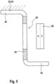
- Fig. 5 shows a sectional view through part of a sliding door device 1 according to a further embodiment, the sliding door 2 being here in an intermediate position between the closed position and the open position.
- the sliding door 2 for example, also carries the first permanent magnet 30.
- a local through opening 50 is formed in the wall, for example, of the second leg 42 of the carrier plate 24.
- the carrier plate 24 is in turn made of magnetically conductive material. Consequently, in the intermediate position, the first permanent magnet 30 approximately overlaps with this through opening 50, in which case the magnetic resistance is relatively large because the air in the through opening 50 has only a very low magnetic conductivity.
- a magnetic reluctance force 48 now arises, which attempts to pull the first permanent magnet 30 together with the sliding door 2 into areas with higher magnetic conductivity of the carrier plate 24. Therefore, the reluctance force 48 acts in the direction of displacement 8 towards the edge of the through opening 50 in the carrier plate 24 there. This is because a type of local or relative accumulation of magnetically conductive material is present in the areas of the carrier plate 24 adjacent to the through opening 50, which then have a greater magnetic conductivity than the through opening 50.
- the magnetic reluctance force 48 which acts on the sliding door 2 in the open position, is therefore based on a difference in the magnetic conductivity between a first section of the carrier plate 24 in the form of the unperforated wall ("local accumulation of magnetically conductive material") of the magnetic conductive material existing carrier plate 24 and a second section of the carrier plate 24 in the form of the through opening 50 ("local reduction of magnetically conductive material"), the first and second sections, seen in the displacement direction 8, arranged one behind the other in the open position of the sliding door and offset from one another are offset.
- the difference in magnetic conductivity between the first section (continuous wall) and the second section of the carrier plate (through opening) can generally be generated by a different volume, a different area and / or a different mass of magnetically conductive material.
- the magnetically conductive element 32 could also be rigidly attached to the door frame 6 or rigidly connected to these components in such a way that a magnetic reluctance force 48 is generated in the form of a magnetic attraction or repulsion force, which pulls or pushes the sliding door 2 into the open position or holds it in the open position.
- first permanent magnet 30 is statically connected to the sliding door 2 and the magnetically conductive element 32 to the door frame 6 or the door guide 22.
- the relationships can also be reversed.
- the first permanent magnet 30 and the magnetically conductive element 32 are then to be arranged as in a sliding door device in such a way that the magnetic reluctance force 48 acts in the phase of moving the pivoting sliding door in order to achieve the desired holding of the pivoting sliding door in the open position.
Landscapes
- Engineering & Computer Science (AREA)
- Mechanical Engineering (AREA)
- Physics & Mathematics (AREA)
- Electromagnetism (AREA)
- Power-Operated Mechanisms For Wings (AREA)
Description
- Die Erfindung betrifft eine Fahrzeugtürvorrichtung gemäß dem Oberbegriff von Anspruch 1. Die Erfindung betrifft auch ein Fahrzeug, insbesondere ein Schienenfahrzeug mit wenigstens einer solchen Fahrzeugtürvorrichtung gemäß Anspruch 6.
- Bei einer solchen Fahrzeugtürvorrichtung kann bei einer in Fahrtrichtung des Fahrzeugs gesehen vorliegenden Schräglage des Fahrzeugs die Öffnungsstellung der Schiebetüre oder Schwenkschiebetüre nur durch eine (weitere) Aktivierung der Antriebseinrichtung oder durch eine erst in Öffnungsstellung aktivierte Verriegelung gehalten werden, um beispielsweise einen Ein- oder Ausstieg von Personen in das Fahrzeug oder aus dem Fahrzeug oder ein Be- oder Entladen des Fahrzeugs zu ermöglichen. Dies ist dann allerdings nur möglich, wenn eine funktionsfähige Energiequelle, z.B. elektrischer Strom vorhanden ist, welcher die Antriebseinrichtung und/oder die Verriegelung mit Energie versorgt.
- Eine gattungsgemäße Fahrzeugtürvorrichtung wird in
WO 2015/199632 A1 offenbart. Dort sind an einer Fahrzeugtüre ein Permanentmagnet sowie ein Vorsprung angeordnet, wobei in der Öffnungsstellung der Türe der Vorsprung einen elektrischen Schalter schaltet, um einen elektrischen Kreis zu trennen, in welchen ein am Chassis angeordneter Elektromagnet geschaltet ist. In der Öffnungsstellung der Türe ist eine magnetische Anziehungskraft zwischen einem Kern des Elektromagneten und dem Permanentmagneten vorhanden. -
FR 2 960 899 A1 -
WO 2017/123908 A1 offenbart ein Dämpfungssystem mit einem an einer Türführung geführten Türblatt, wobei das Dämpfungssystem einen Zylinder-Kolbentrieb sowie einen Permanentmagneten umfasst. -
DE 10 2015 210 593 B3 offenbart eine Vorrichtung zum Halten und/oder Bremsen einer Tür mit einem fixierten ersten Magneten und einem mit der Tür verbundenen zweiten Magneten, wobei die Tür durch die Anziehungskraft zwischen den beiden Magneten in einer Türposition gehalten werden kann. - Der vorliegenden Erfindung liegt die Aufgabe zugrunde, eine eingangs genannte Fahrzeugtürvorrichtung derart weiterzubilden, dass sie es bei einfachem Aufbau ermöglicht, dass die Schiebetüre oder Schwenkschiebetüre ohne Einsatz von Fremdenergie in die Öffnungsstellung gedrängt oder in der Öffnungsstellung gehalten wird. Ebenso soll ein Fahrzeug mit einer solchen Fahrzeugtürvorrichtung zur Verfügung gestellt werden.
- Diese Aufgabe wird erfindungsgemäß durch die Merkmale der Ansprüche 1 und 6 gelöst.
- Die Erfindung geht aus von einer Fahrzeugtürvorrichtung, umfassend wenigstens Folgendes: Wenigstens eine gegenüber einem eine Türöffnung aufweisenden Türrahmen in einer Verschieberichtung verschiebbare Schiebetüre oder in einer Schwenkrichtung schwenkbare und in einer Verschieberichtung verschiebbare Schwenkschiebetüre, eine Antriebseinrichtung, durch welche die wenigstens eine Schiebetüre oder Schwenkschiebetüre in eine die Türöffnung verschließenden Schließstellung und in eine die Türöffnung frei gebende Öffnungsstellung sowie in beliebige Zwischenstellungen zwischen der Schließstellung und der Öffnungsstellung bewegbar ist, eine Türführung zur Führung der wenigstens einen Schiebetüre oder Schwenkschiebetüre relativ zur Türöffnung.
- Unter einem Fahrzeug soll hier jegliche Art von Fahrzeugen verstanden werden, also spurgebundene Fahrzeuge (Schienenfahrzeuge) und auch nicht spurgebundene Fahrzeuge, Fahrzeuge mit Antriebsmaschine wie Kraftfahrzeuge und Triebfahrzeuge, und Fahrzeuge ohne Antriebsmaschine wie Anhänger oder Wagen in Schienenfahrzeugverbänden.
- Eine (reine) Schiebetüre ist bekanntermaßen in einer oder entlang einer Verschieberichtung zwischen der Schließstellung und der Öffnungsstellung verschiebbar gelagert, während eine Schwenkschiebetür ausgehend von der Schließstellung in einer Schwenkrichtung zunächst verschwenkt und dann in einer Verschieberichtung verschoben wird, bis die Öffnungsstellung erreicht ist. Umgekehrt wird eine Schwenkschiebetüre ausgehend von der Öffnungsstellung zunächst entlang der Verschieberichtung verschoben und dann in einer Schenkrichtung verschwenkt, um die Schließstellung einzunehmen. Eine Schwenkschiebetüre führt daher eine kombinierte Schwenk- und Verschiebebewegung aus.
- Die Türführung zur Führung der wenigstens einen Schiebetüre oder Schwenkschiebetüre entlang des Verschieberichtung bzw. entlang der Schwenkrichtung ist beispielsweise an einem Wagenkasten des Fahrzeugs befestigt, welcher die Türöffnung aufweist.
- Weiterhin ist eine stromlos wirkende Magneteinrichtung vorgesehen, die wenigstens einen ersten Permanentmagneten und wenigstens ein magnetisch leitfähiges Element beinhaltet und die eine ohne Einwirkung von elektrischem Strom erzeugte magnetische Kraft auf die wenigstens eine Schiebetüre oder Schwenkschiebetüre derart direkt oder indirekt ausübt, dass die wenigstens eine Schiebetüre oder Schwenkschiebetüre ausgehend von einer Zwischenstellung in die Öffnungsstellung gedrängt und/oder in der bereits eingenommenen Öffnungsstellung gehalten wird, wobei die magnetische Kraft als magnetische Anziehungskraft zwischen dem wenigstens einen ersten Permanentmagneten und dem wenigstens einen magnetisch leitfähigen Element wirkt.
- Unter einem magnetisch leitfähigen Element soll insbesondere ein Element verstanden werden, welches zumindest teilweise aus einem ferromagnetischen oder paramagnetischen Material besteht. Auch unterscheidet sich das wenigstens eine magnetisch leitfähige Element von einem Permanentmagneten.
- Eine direkte Ausübung der magnetischen Kraft auf die Schiebetüre oder die Schwenkschiebetüre meint, dass sie unmittelbar an der Schiebetüre oder Schwenkschiebetüre angreift. Eine indirekte Ausübung der magnetischen Kraft auf die Schiebetüre oder die Schwenkschiebetüre meint, dass sie mittelbar an der Schiebetüre oder Schwenkschiebetüre angreift, insbesondere an wenigstens einem mit der Schiebetüre oder Schwenkschiebetüre verbundenen Element, welches auch ein Bestandteil der Antriebseinrichtung oder im Kraftfluss der Antriebseinrichtung angeordnet sein kann.
- Weil bei Schwenkschiebetüren eine erste Bewegung aus der Schließstellung heraus meist eine Schwenkbewegung ist, an welche sich dann eine zweite Bewegung als reine Verschiebebewegung bis zum Erreichen der Öffnungsstellung anschließt, wirkt die magnetische Kraft gegen Ende der Verschiebebewegung, bevorzugt kurz bevor die Schwenkschiebetüre die Öffnungsstellung erreicht hat und insbesondere auch in der Öffnungsstellung.
- Im Falle einer Schiebtüre wirkt die magnetische Kraft ebenfalls gegen Ende der Verschiebebewegung, bevorzugt kurz bevor die Schwenkschiebetüre die Öffnungsstellung erreicht hat und insbesondere auch in der Öffnungsstellung.
- In einer Richtung senkrecht zur Ebene der Schiebetüre oder zur Schwenkschiebetüre gesehen überdecken sich dann der wenigstens eine erste Permanentmagnet und das wenigstens eine magnetisch leitfähige Element in der Öffnungsstellung wenigstens teilweise.
- Dadurch ist zum Halten der wenigstens einen Schiebetüre oder Schwenkschiebetüre in der Öffnungsstellung oder zum Drängen dahin kein elektrischer Strom notwendig. Vielmehr sorgt dann die magnetische Kraft für ein Zubewegen der wenigstens einen Schiebetüre oder Schwenkschiebetüre in die Öffnungsstellung oder für ein dortiges Halten.
- Gemäß der Erfindung sind der wenigstens eine erste Permanentmagnet mit der wenigstens einen Schiebetüre oder Schwenkschiebetüre und das wenigstens eine magnetisch leitfähige Element mit dem Türrahmen oder der Türführung jeweils statisch verbunden, wobei im Vergleich zu an das wenigstens eine magnetisch leitfähige Element angrenzenden Bereichen des Türrahmens oder der Türführung das wenigstens eine magnetisch leitfähige Element abhängig von dem Volumen, der Fläche und/oder von der Masse an magnetisch leitfähigem Material eine höhere oder niedrigere magnetische Leitfähigkeit besitzt, um sich hinsichtlich der magnetischen Leitfähigkeit von den angrenzenden Bereichen zu unterscheiden.
- Alternativ sind gemäß der Erfindung der wenigstens eine erste Permanentmagnet mit dem Türrahmen oder der Türführung und das wenigstens eine magnetisch leitfähige Element mit der wenigstens einen Schiebetüre oder Schwenkschiebetüre jeweils statisch verbunden, wobei im Vergleich zu an das wenigstens eine magnetisch leitfähige Element angrenzenden Bereichen der Schiebetüre oder Schwenkschiebetüre das wenigstens eine magnetisch leitfähige Element abhängig von dem Volumen, der Fläche und/oder von der Masse an magnetisch leitfähigem Material eine höhere oder niedrigere magnetische Leitfähigkeit besitzt, um sich hinsichtlich der magnetischen Leitfähigkeit von den angrenzenden Bereichen zu unterscheiden.
- In den Unteransprüchen sind vorteilhafte Weiterbildungen der in Anspruch 1 angegebenen Erfindung möglich.
- Zusätzlich zwischen dem wenigstens einen ersten Permanentmagnet und dem wenigstens einen magnetisch leitfähigen Element kann ein Luftspalt minimal sein, wenn sich die wenigstens eine Schiebetüre oder Schwenkschiebetüre in der Öffnungsstellung befindet.
- Beispielsweise kann das wenigstens eine magnetisch leitfähige Element eine relative oder lokale Anhäufung (z. B. in Bezug auf Volumen und/oder Masse und/oder Fläche) von magnetisch leitendem Material bilden. Dann kann beispielsweise eine magnetische Anziehungskraft zwischen dem wenigstens einen Permanentmagneten und dem wenigstens einen magnetisch leitfähigen Element dafür sorgen, dass die wenigstens eine Schiebetüre oder Schiebeschwenktüre in die Öffnungsstellung gedrängt oder in der Öffnungsstellung gehalten wird.
- Alternativ kann das wenigstens eine magnetisch leitfähige Element auch eine lokale oder relative Reduktion (z. B. in Bezug auf Volumen und/oder Masse und/oder Fläche) von magnetisch leitendem Material ausbilden, indem beispielsweise in einem magnetisch leitenden Material eine Ausnehmung oder eine Durchgangsöffnung vorhanden ist, welche dann eine geringere magnetische Leitfähigkeit aufweist im Vergleich zu an das wenigstens eine magnetisch leitfähige Element angrenzenden Bereichen aus magnetisch leitfähigem Material. Überdeckt sich daher der wenigstens eine erste Permanentmagnet in einer Zwischenstellung mit einer solchen lokalen oder relativen Reduktion an magnetisch leitfähigem Material, so ist in dieser Überdeckungsstellung zwischen dem ersten Permanentmagneten und der lokalen Reduktion der magnetische Widerstand relativ groß. Folglich entsteht eine magnetische Anziehungskraft zwischen den an die relative oder lokale Reduktion angrenzenden Bereichen mit höherer magnetischer Leitfähigkeit (welche dann relative Anhäufungen an magnetisch leitendem Material bilden) und dem wenigstens einen ersten Permanentmagneten, welche die wenigstens eine Schiebetüre oder Schiebeschwenktüre in die Öffnungsstellung drängt oder in der Öffnungsstellung hält. Damit dieser Effekt eintreten kann, müssen der wenigstens eine erste Permanentmagnet und das wenigstens eine magnetisch leitfähige Element an geeigneten Stellen mit der Schiebetüre oder Schiebeschwenktüre bzw. mit dem Türrahmen oder der Türführung verbunden werden. Auch kann ein Luftspalt zwischen dem wenigstens einen ersten Permanentmagneten und dem wenigstens einen magnetisch leitfähigen Element in der Öffnungsstellung minimal sein, so dass auch dadurch der magnetische Widerstand minimal wird.
- Weil der wenigstens eine erste Permanentmagnet und auch das wenigstens eine magnetisch leitfähige Element an der wenigstens einen Schiebetüre oder Schwenkschiebetüre bzw. an dem Türrahmen oder an der Türführung jeweils statisch angeordnet bzw. mit diesen Baugruppen starr verbunden sind, sind auch keine kinematisch zusammen wirkenden mechanischen Komponenten notwendig oder vorhanden, durch welche der wenigstens eine erste Permanentmagnet und/oder das wenigstens eine magnetisch leitfähige Element etwa beweglich (linear, rotatorisch) an dem Türrahmen und/oder an der Türführung und/oder an der wenigstens einen Schiebetüre oder Schenkschiebtüre gelagert sind, um die Richtung der Polarität des wenigstes einen ersten Permanentmagnet und/oder des wenigstens einen magnetisch leitfähigen Elements abhängig vom Verschiebeweg der Schiebetüre oder Schwenkschiebetüre anzupassen. Dies resultiert in einem konstruktiv einfachen Aufbau der Fahrzeugtürvorrichtung.
- Insbesondere wird daher die magnetische Kraft durch die Wechselwirkung zwischen dem wenigstens einen ersten Permanentmagneten und dem wenigstens einen, wenigstens in der Öffnungsstellung im magnetischen Fluss des wenigstens einen ersten Permanentmagneten befindlichen magnetisch leitfähigen Elements erzeugt.
- Die magnetische Kraft ist insbesondere eine magnetische Reluktanzkraft, welche zwischen dem wenigstens einen ersten Permanentmagneten und dem wenigstens einen magnetisch leitfähigen Element derart wirkt, dass sich der magnetische Widerstand des magnetischen Flusses zwischen dem wenigstens einen ersten Permanentmagneten und dem wenigstens einen magnetisch leitfähigen Element verringert oder minimal ist, wenn sich die wenigstens eine Schiebetüre oder Schwenkschiebetüre in der Öffnungsstellung befindet.
- Die Erfindung betrifft auch ein Fahrzeug, insbesondere ein Schienenfahrzeug mit wenigstens einer oben beschriebenen Fahrzeugtürvorrichtung.
- Nachstehend sind Ausführungsbeispiele der Erfindung in der Zeichnung dargestellt und in der nachfolgenden Beschreibung näher erläutert. In der Zeichnung zeigt
- Fig.1
- eine schematische Seitenansicht einer Fahrzeugschiebetürvorrichtung als bevorzugte Ausführungsform der Erfindung mit einer Schiebetüre in Öffnungsstellung;
- Fig.2
- eine Schnittdarstellung entlang der Linie II von
Fig.1 ; - Fig.3
- eine Schnittdarstellung durch einen Teil einer Fahrzeugschiebetürvorrichtung gemäß einer nicht erfindungsgemäßen Ausführungsform;
- Fig. 4
- eine perspektivische Ansicht eines Teils der Fahrzeugschiebetürvorrichtung von
Fig. 3 mit der Schiebetüre in der Öffnungsstellung; - Fig. 5
- eine Schnittdarstellung durch eine Fahrzeugschiebetürvorrichtung gemäß einer weiteren Ausführungsform der Erfindung mit der Schiebetüre in einer Zwischenstellung zwischen einer Schließstellung und einer Öffnungsstellung.
- In
Fig.1 ist eine schematische Seitenansicht einer Schiebetürvorrichtung 1 eines Schienenfahrzeugs als bevorzugte Ausführungsform einer Fahrzeugtürvorrichtung der Erfindung gezeigt. Die Schiebetürvorrichtung 1 ist hier vorzugsweise einflügelig mit nur einem Türflügel oder nur einer Schiebetüre 2 ausgeführt. Alternativ kann die Erfindung auch bei einer mehrflügeligen und insbesondere zweiflügeligen Schiebetürvorrichtung mit zwei Schiebetüren zum Einsatz kommen. - Hier weist die Schiebetürvorrichtung 1 eine gegenüber einem eine Türöffnung 4 aufweisenden Türrahmen 6 oder gegenüber der Türöffnung 4 in einer durch den mit gestrichelter Linie in
Fig. 1 gezeichneten Doppelpfeil 8 symbolisierten Verschieberichtung verschiebbare Schiebetüre 2 auf. Außerdem umfasst die Schiebetürvorrichtung 1 eine hier aus Übersichtlichkeitsgründen nicht gezeigte beispielsweise elektrische Antriebseinrichtung auf, durch welche die Schiebetüre 2 in eine die Türöffnung 4 verschließenden Schließstellung und in eine die Türöffnung 4 frei gebende Öffnungsstellung sowie in beliebige Zwischenstellungen zwischen der Schließstellung und der Öffnungsstellung bewegbar ist. - Im gezeigten Ausführungsbeispiel hat in der Öffnungsstellung (
Fig. 1 ) ein erster vertikaler Schiebetürrand 14 einen ersten vertikalen Rahmenteil 16 des Türrahmens 6 während des Einnehmens der Öffnungsstellung überfahren oder passiert. Der zweite vertikale Schiebetürrand 18 ist in der Öffnungsstellung von einem zweiten vertikalen Rahmenteil 20 des Türrahmens 6 beabstandet, so dass dann die Türöffnung 4 zwischen den beiden vertikalen Rahmenteilen 16, 20 und hier nur teilweise gezeigten horizontalen Rahmenteilen des Türrahmens 6 vollständig frei gegeben ist. - Die Schiebetüre 1 ist an einer hier in Gebrauchslage beispielsweise oberen Türführung 22 in der Verschieberichtung 8 verschieblich gelagert, wobei die Türführung 22 hier beispielsweise ein oberes Trägerblech 24 beinhaltet, das an einem Wagenkasten 26 des Schienenfahrzeugs gehalten wird. Die Türführung 22 ist dabei beispielsweise mehr als doppelt so lang als die Breite der Türöffnung 4, damit diese vollständig freigegeben werden kann, wie anhand von
Fig. 1 leicht vorstellbar ist. Weiterhin ist das obere Trägerblech 24 parallel zu einem oberen horizontalen Rahmenteil des Türrahmens 6 angeordnet. Neben dem oberen Trägerblech 24 kann die Türführung 22 noch weitere Trägerelemente aufweisen, durch welche die Schiebetüre 2 an dem Wagenkasten 26 verschieblich gelagert ist. - Die Schiebetürvorrichtung 1 umfasst weiterhin eine stromlos wirkende Magneteinrichtung 28, die eine ohne Einwirkung von elektrischem Strom erzeugte magnetische Kraft 48 auf die Schiebetüre 2 derart ausübt, dass die Schiebetüre 2 beispielsweise in der in
Fig. 1 gezeigten Öffnungsstellung gehalten wird. - Im Ausführungsbeispiel von
Fig. 1 beinhaltet die Magneteinrichtung 28 beispielsweise einen ersten Permanentmagneten 30 sowie ein magnetisch leitfähiges Element 32, wobei der erste Permanentmagnet 30 beispielsweise mit der Schiebetüre 2 und das magnetisch leitfähige Element 32 beispielsweise mit der Türführung 22 jeweils statisch oder starr verbunden ist. Denkbar ist jedoch auch die umgekehrte Anordnung von erstem Permanentmagneten 30 und magnetisch leitfähigem Element 32, so dass dann der erste Permanentmagnet 30 mit der Türführung 22 und das magnetisch leitfähige Element 32 mit der Schiebetüre 2 jeweils statisch oder starr verbunden ist. - Wie
Fig. 2 zeigt, hat das hier wenigstens einen Teil der Türführung 22 ausbildende obere Trägerblech 24 beispielsweise einen annährend Z-förmigen Querschnitt, wobei ein erster in einer in Gebrauchslage horizontalen Ebene verlaufender Schenkel 34 des Trägerblechs 24 beispielsweise eine ebene Laufrollenbahn für Laufrollen 36 ausbildet, welche an Verbindungsteilen 38 um Rotationsachsen 40 drehbar gehalten sind, welche senkrecht zur Ebene der Schiebetüre 2 ausgerichtet sind. Die Verbindungsteile 38 verbinden die Laufrollen 36 mit der Schiebetüre 2, so dass die Schiebetüre 2 über die Laufrollen 36 in der Verschieberichtung 8 gegenüber dem Türrahmen 6 und entlang des Trägerblechs 24 verschieb- oder rollbar ist. Ein zweiter, in Gebrauchslage etwa vertikal ausgerichteter Schenkel 42 des Trägerblechs 24 trägt das magnetisch leitfähige Element 32 insbesondere in Form eines beispielsweise kubischen Körpers, der aus magnetisch hoch leitfähigem ferromagnetischem Material besteht. Der dritte Schenkel 44 des Trägerblechs 24 ist mit dem Wagenkasten 26 des Schienenfahrzeugs verbunden. Das Trägerblech 24 selbst ist wegen seiner relativ geringen Wandstärke gegenüber dem magnetisch leitfähigen Element 32 in geringerem Maße magnetisch leitfähig. Das magnetisch leitfähige Element 32 bildet folglich eine Art von lokaler oder relativer Anhäufung von magnetisch leitfähigem Material gegenüber dem Trägerblech 24. - Im vorliegenden Beispiel sind zwei Laufrollen 36 mit je einem Verbindungsteil 38 an einem in Gebrauchslage oberen horizontalen Schiebetürrand jeweils endseitig, d. h. im Bereich der beiden vertikalen Schiebetürränder 14, 18 vorhanden. Dabei ist an der Laufrolle 36, die in
Fig. 1 zu dem vertikalen ersten Rahmenteil 16 des Türrahmens 6 weist, beispielsweise dem Verbindungsteil 38 gegenüberliegend ein Tragteil 46 vorhanden, welches mit dem Verbindungsteil 38 und damit auch mit der Schiebetüre 2 verbunden ist. Die Laufrolle 36 ist dann beispielsweise an dem Verbindungsteil 38 und dem Tragteil 46 rotatorisch gelagert. Das Tragteil 46 trägt hier beispielsweise den ersten Permanentmagneten 30. In einer Richtung senkrecht zur Ebene der Schiebetüre 2 gesehen überdecken der an der Schiebetüre 2 befestigte erste Permanentmagnet 30 und das an dem Trägerblech 24 befestigte magnetisch leitfähige Element 32 dann beispielsweise wenigstens teilweise in der Öffnungsstellung der Schiebetüre 2, wie inFig. 2 gezeigt ist. - Im Folgenden sei nun der Fall angenommen, dass am Schienenfahrzeug der Strom abgestellt wird oder ausgefallen ist, wenn sich die Schiebetüre 2 in der Öffnungsstellung befindet oder in diese gefahren worden ist und dann die Schiebetüre 2 nicht wie üblich durch eine elektrische Betätigung der Antriebseinrichtung oder durch anderweitige Fremdkräfte in der Öffnungsstellung gehalten werden kann. Falls dann das Schienenfahrzeug auch noch in Fahrrichtung gesehen schräg steht, so könnte die Schiebetüre 2 nicht in der gezeigten Öffnungsstellung gehalten werden.
- In der Öffnungsstellung der Schiebetüre 2 wirkt dann jedoch die magnetische Kraft 48 in Form einer magnetischen Reluktanzkraft zwischen dem ersten Permanentmagneten 30 und dem magnetisch leitfähigen Element 32 derart oder in einer derartigen Richtung, dass sich der magnetische Widerstand des magnetischen Flusses zwischen dem ersten Permanentmagneten 30 und dem magnetisch leitfähigen Element 32 verringert. Folglich wirkt bei dem hier beschriebenen Beispiel in der Öffnungsstellung zwischen dem ersten Permanentmagneten 30 und dem hierzu in Verschieberichtung gesehen dann in Überdeckung befindlichen magnetisch leitfähigen Element 32 die magnetische Reluktanzkraft 48 in Form einer Anziehungskraft, weil hier beispielsweise das Trägerblech 24 gegenüber dem magnetisch leitfähigen Element 32 eine wesentlich geringere magnetische Leitfähigkeit aufweist und die magnetische Reluktanzkraft 48 nun versucht, den magnetischen Widerstand durch Halten des ersten Permanentmagneten 30 in Überdeckungsstellung zum magnetisch leitfähigen Element 32 zu reduzieren. In der Öffnungsstellung der Schiebetüre 2 ist beispielsweise auch ein Luftspalt d zwischen dem ersten Permanentmagneten 30 und dem magnetisch leitfähigen Element 32 minimal, so dass in der Öffnungsstellung der Schiebetüre 2 der magnetische Widerstand des magnetischen Flusses zwischen dem ersten Permanentmagneten 30 und dem magnetisch leitfähigen Element 32 minimal ist.
- Die magnetische Reluktanzkraft 48 hält dann die Schiebetüre 2 in der Öffnungsstellung, weil der erste Permanentmagnet 30 an der Schiebetüre 2 sich mit dem magnetisch leitfähigen Element 32 an dem Trägerblech 24 der Türführung 22 überdeckt und zudem dort der Luftspalt d zwischen dem ersten Permanentmagneten 30 und dem magnetisch leitfähigen Element 32 minimal ist, wobei dann in dieser Position der magnetische Widerstand in Verschieberichtung 8 minimal ist und dann zumindest in Verschieberichtung 8 keine magnetische Reluktanzkraft 48 mehr wirkt.
- Die Schiebetüre 2 kann dann aber ohne weiteres händisch aus der Öffnungsstellung in beliebige Zwischenstellungen und in die Schließstellung bewegt werden. Da die Antriebseinrichtung bei dem hier angenommenen entströmten Zustand keine Gegenkräfte aufzubringen vermag, ist dies auch ohne großen Kraftaufwand zu bewerkstelligen.
- Der Unterschied der nicht erfindungsgemäßen Ausführungsform von
Fig. 3 undFig. 4 zu der Ausführungsform vonFig. 1 undFig. 2 besteht darin, dass das am Trägerblech 24 befestigte magnetisch leitfähige Element 32 durch einen zweiten Permanentmagneten gebildet wird, welcher sich dann in der Öffnungsstellung der Schiebetüre 2 ebenfalls in einer Überdeckungsstellung in Bezug zu dem ersten Permanentmagneten 30 befindet, welcher an der Schiebetüre 2 befestigt ist. Die Polarisierung des ersten Permanentmagneten 30 und des zweiten Permanentmagneten 32 ist dann dergestalt, dass sich in der inFig. 4 gezeigten Überdeckungsstellung, welche der Öffnungsstellung entspricht, ungleichnamige Pole (Nordpol und Südpol) gegenüberliegen, so dass dann eine magnetische Anziehungskraft als Reluktanzkraft 48 zwischen den beiden Permanentmagneten 30, 32 wirkt, welche die Schiebetüre 2 in der Öffnungsstellung halten. -
Fig. 5 stellt eine Schnittdarstellung durch einen Teil einer Schiebetürvorrichtung 1 gemäß einer weiteren Ausführungsform dar, wobei die Schiebetüre 2 sich hier in einer Zwischenstellung zwischen der Schließstellung und der Öffnungsstellung befindet. Bei dieser Ausführungsform trägt die Schiebetüre 2 beispielsweise ebenfalls den ersten Permanentmagneten 30. In der Zwischenstellung dem ersten Permanentmagneten 30 gegenüberliegend ist eine lokale Durchgangsöffnung 50 in der Wandung beispielsweise des zweiten Schenkels 42 des Trägerblechs 24 ausgebildet. Das Trägerblech 24 ist wiederum aus magnetisch leitfähigem Material. Folglich überdeckt sich in der Zwischenstellung der erste Permanentmagnet 30 annähernd mit dieser Durchgangsöffnung 50, wobei dann der magnetische Widerstand relativ groß ist, weil die Luft in der Durchgangsöffnung 50 nur eine sehr geringe magnetische Leitfähigkeit aufweist. Zum Reduzieren des magnetischen Widerstands entsteht nun eine magnetische Reluktanzkraft 48, welche versucht, den ersten Permanentmagneten 30 zusammen mit der Schiebetüre 2 in Bereiche mit höherer magnetischer Leitfähigkeit des Trägerblechs 24 zu ziehen. Daher wirkt die Reluktanzkraft 48 in Verschieberichtung 8 gesehen zum Rand der Durchgangsöffnung 50 im Trägerblech 24 hin. Denn an den an die Durchgangsöffnung 50 angrenzenden Bereichen des Trägerblechs 24 ist eine Art von lokaler oder relativer Anhäufung von magnetisch leitfähigem Material vorhanden, welche dann demgegenüber der Durchgangsöffnung 50 eine größere magnetische Leitfähigkeit besitzen. - Die magnetische Reluktanzkraft 48, welche auf die Schiebetüre 2 in der Öffnungsstellung wirkt, basiert daher auf einem Unterschied in der magnetischen Leitfähigkeit zwischen einem ersten Abschnitt des Trägerblechs 24 in Form der nicht durchbrochenen Wandung ("lokale Anhäufung von magnetisch leitfähigem Material") des aus magnetisch leitfähigem Material bestehenden Trägerblechs 24 und einem zweiten Abschnitt des Trägerblechs 24 in Form der Durchgangsöffnung 50 ("lokale Reduktion von magnetisch leitfähigem Material"), wobei die ersten und zweiten Abschnitte in Verschieberichtung 8 gesehen in der Öffnungsstellung der Schiebetüre hintereinander angeordnet und um einen Versatz gegeneinander versetzt sind. Der Unterschied in der magnetischen Leitfähigkeit zwischen dem ersten Abschnitt (durchgehende Wandung) und dem zweiten Abschnitt des Trägerblechs (Durchgangsöffnung) kann allgemein durch ein unterschiedliches Volumen, eine unterschiedliche Fläche und/oder eine unterschiedliche Masse von magnetisch leitfähigem Material erzeugt werden.
- Anstatt an dem Trägerblech 24 bzw. an der Türführung 22 könnte das magnetisch leitfähige Element 32 auch am Türrahmen 6 derart starr befestigt oder mit diesen Bauteilen derart starr verbunden sein, dass eine magnetische Reluktanzkraft 48 in Form einer magnetischen Anziehungs- oder Abstoßungskraft erzeugt wird, welche die Schiebetüre 2 in die Öffnungsstellung zieht oder schiebt oder in der Öffnungsstellung hält.
- Weiterhin kommt es nicht darauf an, dass der erste Permanentmagnet 30 mit der Schiebetüre 2 statisch verbunden ist und das magnetisch leitfähige Element 32 mit dem Türrahmen 6 oder der Türführung 22. Die Verhältnisse können auch umgekehrt werden.
- Das oben beschriebene Prinzip einer stromlosen Offenhaltefunktion für eine Schiebetüre 2 einer Schiebetürvorrichtung 1 mit Hilfe einer magnetischen Reluktanzkraft 48 ist ohne weiteres auch auf eine Schwenkschiebetürvorrichtung mit wenigstens einer Schwenkschiebetüre übertragbar, wobei der einzige Unterschied darin besteht, dass die Schwenkschiebetüre ausgehend von der Schließstellung zunächst eine Schwenkbewegung ausführt, welche durch die Türführung dann später in eine reine Verschiebebewegung übergeht, an deren Ende sich dann die Öffnungsstellung befindet. Der erste Permanentmagnet 30 und das magnetisch leitfähige Element 32 sind dann wie bei einer Schiebetürvorrichtung so anzuordnen, dass die magnetische Reluktanzkraft 48 in der Phase des Verschiebens der Schwenkschiebetüre wirkt, um das gewünschte Halten der Schwenkschiebetüre in der Öffnungsstellung zu erreichen.
-
- 1
- Schiebetürvorrichtung
- 2
- Schiebetüre
- 4
- Türöffnung
- 6
- Türrahmen
- 8
- Verschieberichtung
- 14
- erster vertikaler Schiebetürrand
- 16
- erstes vertikales Rahmenteil
- 18
- zweiter vertikaler Schiebetürrand
- 20
- zweites vertikales Rahmenteil
- 22
- Türführung
- 24
- oberes Trägerblech
- 26
- Wagenkasten
- 28
- Magneteinrichtung
- 30
- erster Permanentmagnet
- 32
- magnetisch leitfähiges Element
- 34
- erster Schenkel
- 36
- Laufrollen
- 38
- Verbindungsteil
- 40
- Rotationsachse
- 42
- zweiter Schenkel
- 44
- dritter Schenkel
- 46
- Tragteil
- 48
- Reluktanzkraft
- 50
- Durchgangsöffnung
Claims (6)
- Fahrzeugtürvorrichtung (1), umfassend wenigstens Folgendes:a) Wenigstens eine gegenüber einem eine Türöffnung (4) aufweisenden Türrahmen (6) in einer Verschieberichtung (8) verschiebbare Schiebetüre (2) oder in einer Schwenkrichtung schwenkbare und in einer Verschieberichtung verschiebbare Schwenkschiebetüre,b) eine Antriebseinrichtung, durch welche die wenigstens eine Schiebetüre (2) oder Schwenkschiebetüre in eine die Türöffnung (4) verschließende Schließstellung und in eine die Türöffnung (4) frei gebende Öffnungsstellung sowie in beliebige Zwischenstellungen zwischen der Schließstellung und der Öffnungsstellung bewegbar ist,c) eine Türführung (22, 24) zur Führung der wenigstens einen Schiebetüre (2) oder Schwenkschiebetüre relativ zur Türöffnung (4),d) eine stromlos wirkende Magneteinrichtung (28), die wenigstens einen ersten Permanentmagneten (30) und wenigstens ein magnetisch leitfähiges Element (32) beinhaltet und die eine ohne Einwirkung von elektrischem Strom erzeugte magnetische Kraft (48) auf die wenigstens eine Schiebetüre (2) oder Schwenkschiebetüre derart direkt oder indirekt ausübt, dass die wenigstens eine Schiebetüre (2) oder Schwenkschiebetüred1) ausgehend von einer Zwischenstellung in die Öffnungsstellung gedrängt, und/oderd2) in der bereits eingenommenen Öffnungsstellung gehalten wird, wobei die magnetische Kraft (48) als magnetische Anziehungskraft zwischen dem wenigstens einen ersten Permanentmagneten (30) und dem wenigstens einen magnetisch leitfähigen Element (32) wirkt, dadurch gekennzeichnet, dass in einer Richtung senkrecht zur Ebene der Schiebetüre (2) oder zur Schwenkschiebetüre gesehen sich der wenigstens eine erste Permanentmagnet (30) und das wenigstens eine magnetisch leitfähige Element (32) in der Öffnungsstellung wenigstens teilweise überdecken, und dass sich das wenigstens eine magnetisch leitfähige Element (32) von einem Permanentmagneten unterscheidet, und dass entweder der wenigstens eine erste Permanentmagnet (30) mit der wenigstens einen Schiebetüre (2) oder Schwenkschiebetüre und das wenigstens eine magnetisch leitfähige Element (32) mit dem Türrahmen (6) oder der Türführung (22, 24) jeweils statisch verbunden sind, und dass im Vergleich zu an das wenigstens eine magnetisch leitfähige Element (32) angrenzenden Bereichen des Türrahmens (6) oder der Türführung (22, 24) das wenigstens eine magnetisch leitfähige Element (32) abhängig von dem Volumen, der Fläche und/oder von der Masse an magnetisch leitfähigem Material eine höhere magnetische Leitfähigkeit besitzt, oder der wenigstens eine erste Permanentmagnet (30) mit dem Türrahmen (6) oder der Türführung (22, 24) und das wenigstens eine magnetisch leitfähige Element (32) mit der wenigstens einen Schiebetüre (2) oder Schwenkschiebetüre jeweils statisch verbunden sind, und dass im Vergleich zu an das wenigstens eine magnetisch leitfähige Element (32) angrenzenden Bereichen der Schiebetüre (2) oder Schwenkschiebetüre das wenigstens eine magnetisch leitfähige Element (32) abhängig von dem Volumen, der Fläche und/oder von der Masse an magnetisch leitfähigem Material eine höhere magnetische Leitfähigkeit besitzt.
- Fahrzeugtürvorrichtung nach Anspruch 1, dadurch gekennzeichnet, dass zwischen dem wenigstens einen ersten Permanentmagnet (30) und dem wenigstens einen magnetisch leitfähigen Element (32) ein Luftspalt (d) minimal ist, wenn sich die wenigstens eine Schiebetüre (2) oder Schwenkschiebetüre in der Öffnungsstellung befindet.
- Fahrzeugtürvorrichtung nach einem der vorhergehenden Ansprüche, dadurch gekennzeichnet, dass das wenigstens eine magnetisch leitfähige Element (32) eine lokale Anhäufung von magnetisch leitfähigem Material bildet.
- Fahrzeugtürvorrichtung nach einem der vorhergehenden Ansprüche, dadurch gekennzeichnet, dass die magnetische Kraft (48) durch die Wechselwirkung zwischen dem wenigstens einen ersten Permanentmagneten (30) und dem wenigstens einen, wenigstens in der Öffnungsstellung im magnetischen Fluss des wenigstens einen ersten Permanentmagneten (30) befindlichen magnetisch leitfähigen Element (32) erzeugt wird.
- Fahrzeugtürvorrichtung nach einem der vorhergehenden Ansprüche, dadurch gekennzeichnet, dass die magnetische Kraft (48) eine magnetische Reluktanzkraft ist, welche zwischen dem wenigstens einen ersten Permanentmagneten (30) und dem wenigstens einen magnetisch leitfähigen Element (32) derart wirkt, dass sich der magnetische Widerstand des magnetischen Flusses zwischen dem wenigstens einen ersten Permanentmagneten (30) und dem wenigstens einen magnetisch leitfähigen Element (32) verringert oder minimal ist, wenn sich die wenigstens eine Schiebetüre (2) oder Schwenkschiebetüre in der Öffnungsstellung befindet.
- Fahrzeug, insbesondere Schienenfahrzeug mit wenigstens einer Fahrzeugtürvorrichtung (1) nach einem der vorhergehenden Ansprüche.
Applications Claiming Priority (2)
| Application Number | Priority Date | Filing Date | Title |
|---|---|---|---|
| DE102019003808.8A DE102019003808A1 (de) | 2019-05-31 | 2019-05-31 | Fahrzeugtürvorrichtung mit stromloser Offenhaltefunktion |
| PCT/EP2020/063790 WO2020239492A1 (de) | 2019-05-31 | 2020-05-18 | Fahrzeugtürvorrichtung mit stromloser offenhaltefunktion |
Publications (2)
| Publication Number | Publication Date |
|---|---|
| EP3976916A1 EP3976916A1 (de) | 2022-04-06 |
| EP3976916B1 true EP3976916B1 (de) | 2024-03-20 |
Family
ID=70847338
Family Applications (1)
| Application Number | Title | Priority Date | Filing Date |
|---|---|---|---|
| EP20727948.0A Active EP3976916B1 (de) | 2019-05-31 | 2020-05-18 | Fahrzeugtürvorrichtung mit stromloser offenhaltefunktion |
Country Status (5)
| Country | Link |
|---|---|
| EP (1) | EP3976916B1 (de) |
| DE (1) | DE102019003808A1 (de) |
| ES (1) | ES2988564T3 (de) |
| PL (1) | PL3976916T3 (de) |
| WO (1) | WO2020239492A1 (de) |
Family Cites Families (5)
| Publication number | Priority date | Publication date | Assignee | Title |
|---|---|---|---|---|
| DE202006017402U1 (de) * | 2006-11-15 | 2006-12-28 | BLASI - GMBH Automatische Türanlagen | Schiebetür |
| FR2960899A1 (fr) * | 2010-06-08 | 2011-12-09 | Jacques Afriat | Systeme de controle du mouvement d’une porte coulissante, notamment d’une porte de placard |
| WO2015199632A1 (en) * | 2014-06-27 | 2015-12-30 | Tofaş Türk Otomobil Fabrikasi Anonim Şirketi | A sliding door system |
| DE102015210593B3 (de) * | 2015-06-10 | 2016-06-16 | Siemens Aktiengesellschaft | Vorrichtung zum Halten und/oder Bremsen einer Tür |
| WO2017123908A1 (en) * | 2016-01-14 | 2017-07-20 | Pemko Manufacturing Company, Inc. | Soft-stop device and system |
-
2019
- 2019-05-31 DE DE102019003808.8A patent/DE102019003808A1/de active Pending
-
2020
- 2020-05-18 ES ES20727948T patent/ES2988564T3/es active Active
- 2020-05-18 PL PL20727948.0T patent/PL3976916T3/pl unknown
- 2020-05-18 WO PCT/EP2020/063790 patent/WO2020239492A1/de not_active Ceased
- 2020-05-18 EP EP20727948.0A patent/EP3976916B1/de active Active
Also Published As
| Publication number | Publication date |
|---|---|
| DE102019003808A1 (de) | 2020-12-03 |
| ES2988564T3 (es) | 2024-11-20 |
| EP3976916A1 (de) | 2022-04-06 |
| WO2020239492A1 (de) | 2020-12-03 |
| PL3976916T3 (pl) | 2024-08-26 |
Similar Documents
| Publication | Publication Date | Title |
|---|---|---|
| EP3775463B1 (de) | Tor mit führungsanordnung | |
| EP0498247B1 (de) | Vorrichtung zum Betätigen und Entriegeln der Schachttüren eines Aufzuges | |
| EP2297421B1 (de) | Türantrieb | |
| EP3976911B1 (de) | Fahrzeugtürvorrichtung mit stromloser öffnungsfunktion | |
| EP2467548A1 (de) | Laufschiene für eine schiebewand und verfahren zur betätigung einer weiche in einer laufschiene | |
| EP3715570B1 (de) | Schiebetüranlage | |
| DE102018123345B4 (de) | Antriebsvorrichtung für elektrische Türen | |
| DE19835678C2 (de) | Elektrisch betätigbare Verriegelungseinrichtung für Türflügel, insbesondere Schiebetürflügel | |
| EP3976916B1 (de) | Fahrzeugtürvorrichtung mit stromloser offenhaltefunktion | |
| EP2165868A1 (de) | Schwenkschiebetürsystem | |
| DE10257673B4 (de) | Verschlussvorrichtung einer in der Karosserie eines Fahrzeuges vorgesehenen Öffnung, und entsprechendes Fahrzeug | |
| DE102016210168B3 (de) | Türantrieb für eine Kraftwagentür | |
| DE102006040070A1 (de) | Fahrzeug mit einer Schiebetüre | |
| DE202016007175U1 (de) | Vorrichtung zum Öffnen und Schließen eines Flügels | |
| DE102019003806A1 (de) | Fahrzeugtürvorrichtung mit Bremsfunktion | |
| DE10257688A1 (de) | Verschussvorrichtung für eine in einem Fahrzeug vorgesehene Öffnung mit einer einzigen Gleitführungsschiene sowie entsprechendes Fahrzeug | |
| DE102018129581B4 (de) | Hilfsantrieb für ein motorisch angetriebenes Torblatt, sowie Tor mit einem Hilfsantrieb | |
| DE202020101360U1 (de) | Tor mit Führungsanordnung | |
| DE102005015797B4 (de) | Sicherheitsschalter, insbesondere für Schutzschranken | |
| EP1681426A2 (de) | Schiebetür mit einem magnetischen Antriebssystem und individuell öffnenden Türflügeln und Verfahren zu deren Ansteuerung | |
| DE2040790A1 (de) | Zellentuer-Betaetigungsvorrichtung | |
| DE202008013553U1 (de) | Beschlag für einen Flügel von Fenstern oder Türen | |
| DE102008011735A1 (de) | Schiebetüranordnung eines Kraftfahrzeugs | |
| DE19638741A1 (de) | Elektromechanischer Antrieb für eine Schiebetür | |
| DE102018115798A1 (de) | Türantrieb für den Antrieb einer Schiebetür eines Fahrzeugs |
Legal Events
| Date | Code | Title | Description |
|---|---|---|---|
| STAA | Information on the status of an ep patent application or granted ep patent |
Free format text: STATUS: UNKNOWN |
|
| STAA | Information on the status of an ep patent application or granted ep patent |
Free format text: STATUS: THE INTERNATIONAL PUBLICATION HAS BEEN MADE |
|
| PUAI | Public reference made under article 153(3) epc to a published international application that has entered the european phase |
Free format text: ORIGINAL CODE: 0009012 |
|
| STAA | Information on the status of an ep patent application or granted ep patent |
Free format text: STATUS: REQUEST FOR EXAMINATION WAS MADE |
|
| 17P | Request for examination filed |
Effective date: 20220103 |
|
| AK | Designated contracting states |
Kind code of ref document: A1 Designated state(s): AL AT BE BG CH CY CZ DE DK EE ES FI FR GB GR HR HU IE IS IT LI LT LU LV MC MK MT NL NO PL PT RO RS SE SI SK SM TR |
|
| DAV | Request for validation of the european patent (deleted) | ||
| DAX | Request for extension of the european patent (deleted) | ||
| STAA | Information on the status of an ep patent application or granted ep patent |
Free format text: STATUS: EXAMINATION IS IN PROGRESS |
|
| 17Q | First examination report despatched |
Effective date: 20230216 |
|
| REG | Reference to a national code |
Ref country code: DE Ref legal event code: R079 Ref document number: 502020007417 Country of ref document: DE Free format text: PREVIOUS MAIN CLASS: E05D0015060000 Ipc: E05C0019160000 Ref country code: DE Ref legal event code: R079 Free format text: PREVIOUS MAIN CLASS: E05D0015060000 Ipc: E05C0019160000 |
|
| RIC1 | Information provided on ipc code assigned before grant |
Ipc: E05C 19/16 20060101AFI20230914BHEP |
|
| GRAP | Despatch of communication of intention to grant a patent |
Free format text: ORIGINAL CODE: EPIDOSNIGR1 |
|
| STAA | Information on the status of an ep patent application or granted ep patent |
Free format text: STATUS: GRANT OF PATENT IS INTENDED |
|
| INTG | Intention to grant announced |
Effective date: 20231026 |
|
| GRAS | Grant fee paid |
Free format text: ORIGINAL CODE: EPIDOSNIGR3 |
|
| GRAA | (expected) grant |
Free format text: ORIGINAL CODE: 0009210 |
|
| STAA | Information on the status of an ep patent application or granted ep patent |
Free format text: STATUS: THE PATENT HAS BEEN GRANTED |
|
| AK | Designated contracting states |
Kind code of ref document: B1 Designated state(s): AL AT BE BG CH CY CZ DE DK EE ES FI FR GB GR HR HU IE IS IT LI LT LU LV MC MK MT NL NO PL PT RO RS SE SI SK SM TR |
|
| REG | Reference to a national code |
Ref country code: GB Ref legal event code: FG4D Free format text: NOT ENGLISH |
|
| REG | Reference to a national code |
Ref country code: CH Ref legal event code: EP |
|
| REG | Reference to a national code |
Ref country code: DE Ref legal event code: R096 Ref document number: 502020007417 Country of ref document: DE |
|
| REG | Reference to a national code |
Ref country code: IE Ref legal event code: FG4D Free format text: LANGUAGE OF EP DOCUMENT: GERMAN |
|
| PG25 | Lapsed in a contracting state [announced via postgrant information from national office to epo] |
Ref country code: LT Free format text: LAPSE BECAUSE OF FAILURE TO SUBMIT A TRANSLATION OF THE DESCRIPTION OR TO PAY THE FEE WITHIN THE PRESCRIBED TIME-LIMIT Effective date: 20240320 |
|
| REG | Reference to a national code |
Ref country code: LT Ref legal event code: MG9D |
|
| PG25 | Lapsed in a contracting state [announced via postgrant information from national office to epo] |
Ref country code: GR Free format text: LAPSE BECAUSE OF FAILURE TO SUBMIT A TRANSLATION OF THE DESCRIPTION OR TO PAY THE FEE WITHIN THE PRESCRIBED TIME-LIMIT Effective date: 20240621 |
|
| PG25 | Lapsed in a contracting state [announced via postgrant information from national office to epo] |
Ref country code: RS Free format text: LAPSE BECAUSE OF FAILURE TO SUBMIT A TRANSLATION OF THE DESCRIPTION OR TO PAY THE FEE WITHIN THE PRESCRIBED TIME-LIMIT Effective date: 20240620 Ref country code: HR Free format text: LAPSE BECAUSE OF FAILURE TO SUBMIT A TRANSLATION OF THE DESCRIPTION OR TO PAY THE FEE WITHIN THE PRESCRIBED TIME-LIMIT Effective date: 20240320 |
|
| REG | Reference to a national code |
Ref country code: NL Ref legal event code: MP Effective date: 20240320 |
|
| PG25 | Lapsed in a contracting state [announced via postgrant information from national office to epo] |
Ref country code: RS Free format text: LAPSE BECAUSE OF FAILURE TO SUBMIT A TRANSLATION OF THE DESCRIPTION OR TO PAY THE FEE WITHIN THE PRESCRIBED TIME-LIMIT Effective date: 20240620 Ref country code: NO Free format text: LAPSE BECAUSE OF FAILURE TO SUBMIT A TRANSLATION OF THE DESCRIPTION OR TO PAY THE FEE WITHIN THE PRESCRIBED TIME-LIMIT Effective date: 20240620 Ref country code: LT Free format text: LAPSE BECAUSE OF FAILURE TO SUBMIT A TRANSLATION OF THE DESCRIPTION OR TO PAY THE FEE WITHIN THE PRESCRIBED TIME-LIMIT Effective date: 20240320 Ref country code: HR Free format text: LAPSE BECAUSE OF FAILURE TO SUBMIT A TRANSLATION OF THE DESCRIPTION OR TO PAY THE FEE WITHIN THE PRESCRIBED TIME-LIMIT Effective date: 20240320 Ref country code: GR Free format text: LAPSE BECAUSE OF FAILURE TO SUBMIT A TRANSLATION OF THE DESCRIPTION OR TO PAY THE FEE WITHIN THE PRESCRIBED TIME-LIMIT Effective date: 20240621 Ref country code: FI Free format text: LAPSE BECAUSE OF FAILURE TO SUBMIT A TRANSLATION OF THE DESCRIPTION OR TO PAY THE FEE WITHIN THE PRESCRIBED TIME-LIMIT Effective date: 20240320 Ref country code: BG Free format text: LAPSE BECAUSE OF FAILURE TO SUBMIT A TRANSLATION OF THE DESCRIPTION OR TO PAY THE FEE WITHIN THE PRESCRIBED TIME-LIMIT Effective date: 20240320 |
|
| P01 | Opt-out of the competence of the unified patent court (upc) registered |
Free format text: CASE NUMBER: APP_35877/2024 Effective date: 20240627 |
|
| PG25 | Lapsed in a contracting state [announced via postgrant information from national office to epo] |
Ref country code: SE Free format text: LAPSE BECAUSE OF FAILURE TO SUBMIT A TRANSLATION OF THE DESCRIPTION OR TO PAY THE FEE WITHIN THE PRESCRIBED TIME-LIMIT Effective date: 20240320 Ref country code: LV Free format text: LAPSE BECAUSE OF FAILURE TO SUBMIT A TRANSLATION OF THE DESCRIPTION OR TO PAY THE FEE WITHIN THE PRESCRIBED TIME-LIMIT Effective date: 20240320 |
|
| PG25 | Lapsed in a contracting state [announced via postgrant information from national office to epo] |
Ref country code: NL Free format text: LAPSE BECAUSE OF FAILURE TO SUBMIT A TRANSLATION OF THE DESCRIPTION OR TO PAY THE FEE WITHIN THE PRESCRIBED TIME-LIMIT Effective date: 20240320 |
|
| PG25 | Lapsed in a contracting state [announced via postgrant information from national office to epo] |
Ref country code: NL Free format text: LAPSE BECAUSE OF FAILURE TO SUBMIT A TRANSLATION OF THE DESCRIPTION OR TO PAY THE FEE WITHIN THE PRESCRIBED TIME-LIMIT Effective date: 20240320 |
|
| PG25 | Lapsed in a contracting state [announced via postgrant information from national office to epo] |
Ref country code: IS Free format text: LAPSE BECAUSE OF FAILURE TO SUBMIT A TRANSLATION OF THE DESCRIPTION OR TO PAY THE FEE WITHIN THE PRESCRIBED TIME-LIMIT Effective date: 20240720 |
|
| PG25 | Lapsed in a contracting state [announced via postgrant information from national office to epo] |
Ref country code: PT Free format text: LAPSE BECAUSE OF FAILURE TO SUBMIT A TRANSLATION OF THE DESCRIPTION OR TO PAY THE FEE WITHIN THE PRESCRIBED TIME-LIMIT Effective date: 20240722 Ref country code: SM Free format text: LAPSE BECAUSE OF FAILURE TO SUBMIT A TRANSLATION OF THE DESCRIPTION OR TO PAY THE FEE WITHIN THE PRESCRIBED TIME-LIMIT Effective date: 20240320 |
|
| PG25 | Lapsed in a contracting state [announced via postgrant information from national office to epo] |
Ref country code: EE Free format text: LAPSE BECAUSE OF FAILURE TO SUBMIT A TRANSLATION OF THE DESCRIPTION OR TO PAY THE FEE WITHIN THE PRESCRIBED TIME-LIMIT Effective date: 20240320 |
|
| PG25 | Lapsed in a contracting state [announced via postgrant information from national office to epo] |
Ref country code: SK Free format text: LAPSE BECAUSE OF FAILURE TO SUBMIT A TRANSLATION OF THE DESCRIPTION OR TO PAY THE FEE WITHIN THE PRESCRIBED TIME-LIMIT Effective date: 20240320 |
|
| PG25 | Lapsed in a contracting state [announced via postgrant information from national office to epo] |
Ref country code: SM Free format text: LAPSE BECAUSE OF FAILURE TO SUBMIT A TRANSLATION OF THE DESCRIPTION OR TO PAY THE FEE WITHIN THE PRESCRIBED TIME-LIMIT Effective date: 20240320 Ref country code: SK Free format text: LAPSE BECAUSE OF FAILURE TO SUBMIT A TRANSLATION OF THE DESCRIPTION OR TO PAY THE FEE WITHIN THE PRESCRIBED TIME-LIMIT Effective date: 20240320 Ref country code: RO Free format text: LAPSE BECAUSE OF FAILURE TO SUBMIT A TRANSLATION OF THE DESCRIPTION OR TO PAY THE FEE WITHIN THE PRESCRIBED TIME-LIMIT Effective date: 20240320 Ref country code: PT Free format text: LAPSE BECAUSE OF FAILURE TO SUBMIT A TRANSLATION OF THE DESCRIPTION OR TO PAY THE FEE WITHIN THE PRESCRIBED TIME-LIMIT Effective date: 20240722 Ref country code: IS Free format text: LAPSE BECAUSE OF FAILURE TO SUBMIT A TRANSLATION OF THE DESCRIPTION OR TO PAY THE FEE WITHIN THE PRESCRIBED TIME-LIMIT Effective date: 20240720 Ref country code: EE Free format text: LAPSE BECAUSE OF FAILURE TO SUBMIT A TRANSLATION OF THE DESCRIPTION OR TO PAY THE FEE WITHIN THE PRESCRIBED TIME-LIMIT Effective date: 20240320 |
|
| REG | Reference to a national code |
Ref country code: ES Ref legal event code: FG2A Ref document number: 2988564 Country of ref document: ES Kind code of ref document: T3 Effective date: 20241120 |
|
| PG25 | Lapsed in a contracting state [announced via postgrant information from national office to epo] |
Ref country code: IT Free format text: LAPSE BECAUSE OF FAILURE TO SUBMIT A TRANSLATION OF THE DESCRIPTION OR TO PAY THE FEE WITHIN THE PRESCRIBED TIME-LIMIT Effective date: 20240320 |
|
| REG | Reference to a national code |
Ref country code: DE Ref legal event code: R097 Ref document number: 502020007417 Country of ref document: DE |
|
| REG | Reference to a national code |
Ref country code: CH Ref legal event code: PL |
|
| PG25 | Lapsed in a contracting state [announced via postgrant information from national office to epo] |
Ref country code: IT Free format text: LAPSE BECAUSE OF FAILURE TO SUBMIT A TRANSLATION OF THE DESCRIPTION OR TO PAY THE FEE WITHIN THE PRESCRIBED TIME-LIMIT Effective date: 20240320 |
|
| PG25 | Lapsed in a contracting state [announced via postgrant information from national office to epo] |
Ref country code: MC Free format text: LAPSE BECAUSE OF FAILURE TO SUBMIT A TRANSLATION OF THE DESCRIPTION OR TO PAY THE FEE WITHIN THE PRESCRIBED TIME-LIMIT Effective date: 20240320 |
|
| PG25 | Lapsed in a contracting state [announced via postgrant information from national office to epo] |
Ref country code: DK Free format text: LAPSE BECAUSE OF FAILURE TO SUBMIT A TRANSLATION OF THE DESCRIPTION OR TO PAY THE FEE WITHIN THE PRESCRIBED TIME-LIMIT Effective date: 20240320 |
|
| PG25 | Lapsed in a contracting state [announced via postgrant information from national office to epo] |
Ref country code: LU Free format text: LAPSE BECAUSE OF NON-PAYMENT OF DUE FEES Effective date: 20240518 |
|
| PLBE | No opposition filed within time limit |
Free format text: ORIGINAL CODE: 0009261 |
|
| STAA | Information on the status of an ep patent application or granted ep patent |
Free format text: STATUS: NO OPPOSITION FILED WITHIN TIME LIMIT |
|
| PG25 | Lapsed in a contracting state [announced via postgrant information from national office to epo] |
Ref country code: MC Free format text: LAPSE BECAUSE OF FAILURE TO SUBMIT A TRANSLATION OF THE DESCRIPTION OR TO PAY THE FEE WITHIN THE PRESCRIBED TIME-LIMIT Effective date: 20240320 Ref country code: LU Free format text: LAPSE BECAUSE OF NON-PAYMENT OF DUE FEES Effective date: 20240518 Ref country code: DK Free format text: LAPSE BECAUSE OF FAILURE TO SUBMIT A TRANSLATION OF THE DESCRIPTION OR TO PAY THE FEE WITHIN THE PRESCRIBED TIME-LIMIT Effective date: 20240320 Ref country code: CH Free format text: LAPSE BECAUSE OF NON-PAYMENT OF DUE FEES Effective date: 20240531 |
|
| REG | Reference to a national code |
Ref country code: BE Ref legal event code: MM Effective date: 20240531 |
|
| 26N | No opposition filed |
Effective date: 20241223 |
|
| PG25 | Lapsed in a contracting state [announced via postgrant information from national office to epo] |
Ref country code: IE Free format text: LAPSE BECAUSE OF NON-PAYMENT OF DUE FEES Effective date: 20240518 |
|
| PG25 | Lapsed in a contracting state [announced via postgrant information from national office to epo] |
Ref country code: SI Free format text: LAPSE BECAUSE OF FAILURE TO SUBMIT A TRANSLATION OF THE DESCRIPTION OR TO PAY THE FEE WITHIN THE PRESCRIBED TIME-LIMIT Effective date: 20240320 Ref country code: BE Free format text: LAPSE BECAUSE OF NON-PAYMENT OF DUE FEES Effective date: 20240531 |
|
| PGFP | Annual fee paid to national office [announced via postgrant information from national office to epo] |
Ref country code: PL Payment date: 20250429 Year of fee payment: 6 Ref country code: DE Payment date: 20250528 Year of fee payment: 6 |
|
| PGFP | Annual fee paid to national office [announced via postgrant information from national office to epo] |
Ref country code: GB Payment date: 20250526 Year of fee payment: 6 Ref country code: ES Payment date: 20250612 Year of fee payment: 6 |
|
| PGFP | Annual fee paid to national office [announced via postgrant information from national office to epo] |
Ref country code: FR Payment date: 20250526 Year of fee payment: 6 |
|
| PGFP | Annual fee paid to national office [announced via postgrant information from national office to epo] |
Ref country code: AT Payment date: 20250520 Year of fee payment: 6 |
|
| PGFP | Annual fee paid to national office [announced via postgrant information from national office to epo] |
Ref country code: CZ Payment date: 20250506 Year of fee payment: 6 |
|
| PG25 | Lapsed in a contracting state [announced via postgrant information from national office to epo] |
Ref country code: CY Free format text: LAPSE BECAUSE OF FAILURE TO SUBMIT A TRANSLATION OF THE DESCRIPTION OR TO PAY THE FEE WITHIN THE PRESCRIBED TIME-LIMIT; INVALID AB INITIO Effective date: 20200518 |
|
| PG25 | Lapsed in a contracting state [announced via postgrant information from national office to epo] |
Ref country code: HU Free format text: LAPSE BECAUSE OF FAILURE TO SUBMIT A TRANSLATION OF THE DESCRIPTION OR TO PAY THE FEE WITHIN THE PRESCRIBED TIME-LIMIT; INVALID AB INITIO Effective date: 20200518 |