EP3976916B1 - Dispositif de porte de véhicule à fonction de maintien en position d'ouverture non électrique - Google Patents
Dispositif de porte de véhicule à fonction de maintien en position d'ouverture non électrique Download PDFInfo
- Publication number
- EP3976916B1 EP3976916B1 EP20727948.0A EP20727948A EP3976916B1 EP 3976916 B1 EP3976916 B1 EP 3976916B1 EP 20727948 A EP20727948 A EP 20727948A EP 3976916 B1 EP3976916 B1 EP 3976916B1
- Authority
- EP
- European Patent Office
- Prior art keywords
- sliding door
- door
- magnetically conductive
- conductive element
- permanent magnet
- Prior art date
- Legal status (The legal status is an assumption and is not a legal conclusion. Google has not performed a legal analysis and makes no representation as to the accuracy of the status listed.)
- Active
Links
- 230000005291 magnetic effect Effects 0.000 claims description 68
- 239000004020 conductor Substances 0.000 claims description 18
- 230000004907 flux Effects 0.000 claims description 6
- 230000009471 action Effects 0.000 claims description 3
- 230000003993 interaction Effects 0.000 claims description 2
- 238000006073 displacement reaction Methods 0.000 description 15
- 230000035508 accumulation Effects 0.000 description 5
- 238000009825 accumulation Methods 0.000 description 5
- 230000009467 reduction Effects 0.000 description 5
- 238000013016 damping Methods 0.000 description 2
- 239000003302 ferromagnetic material Substances 0.000 description 2
- 235000004443 Ricinus communis Nutrition 0.000 description 1
- 240000000528 Ricinus communis Species 0.000 description 1
- 230000003213 activating effect Effects 0.000 description 1
- 238000013459 approach Methods 0.000 description 1
- 230000000712 assembly Effects 0.000 description 1
- 238000000429 assembly Methods 0.000 description 1
- 238000011161 development Methods 0.000 description 1
- 230000018109 developmental process Effects 0.000 description 1
- 230000000694 effects Effects 0.000 description 1
- 230000005294 ferromagnetic effect Effects 0.000 description 1
- 230000003137 locomotive effect Effects 0.000 description 1
- 230000007246 mechanism Effects 0.000 description 1
- 239000002907 paramagnetic material Substances 0.000 description 1
- 230000010287 polarization Effects 0.000 description 1
Images


Classifications
-
- B—PERFORMING OPERATIONS; TRANSPORTING
- B60—VEHICLES IN GENERAL
- B60J—WINDOWS, WINDSCREENS, NON-FIXED ROOFS, DOORS, OR SIMILAR DEVICES FOR VEHICLES; REMOVABLE EXTERNAL PROTECTIVE COVERINGS SPECIALLY ADAPTED FOR VEHICLES
- B60J5/00—Doors
- B60J5/04—Doors arranged at the vehicle sides
- B60J5/06—Doors arranged at the vehicle sides slidable; foldable
- B60J5/062—Doors arranged at the vehicle sides slidable; foldable for utility vehicles or public transport
-
- E—FIXED CONSTRUCTIONS
- E05—LOCKS; KEYS; WINDOW OR DOOR FITTINGS; SAFES
- E05C—BOLTS OR FASTENING DEVICES FOR WINGS, SPECIALLY FOR DOORS OR WINDOWS
- E05C17/00—Devices for holding wings open; Devices for limiting opening of wings or for holding wings open by a movable member extending between frame and wing; Braking devices, stops or buffers, combined therewith
- E05C17/56—Devices for holding wings open; Devices for limiting opening of wings or for holding wings open by a movable member extending between frame and wing; Braking devices, stops or buffers, combined therewith by magnetic or electromagnetic attraction or operated by electric or electromagnetic means
-
- E—FIXED CONSTRUCTIONS
- E05—LOCKS; KEYS; WINDOW OR DOOR FITTINGS; SAFES
- E05D—HINGES OR SUSPENSION DEVICES FOR DOORS, WINDOWS OR WINGS
- E05D15/00—Suspension arrangements for wings
- E05D15/06—Suspension arrangements for wings for wings sliding horizontally more or less in their own plane
-
- E—FIXED CONSTRUCTIONS
- E05—LOCKS; KEYS; WINDOW OR DOOR FITTINGS; SAFES
- E05F—DEVICES FOR MOVING WINGS INTO OPEN OR CLOSED POSITION; CHECKS FOR WINGS; WING FITTINGS NOT OTHERWISE PROVIDED FOR, CONCERNED WITH THE FUNCTIONING OF THE WING
- E05F1/00—Closers or openers for wings, not otherwise provided for in this subclass
-
- E—FIXED CONSTRUCTIONS
- E05—LOCKS; KEYS; WINDOW OR DOOR FITTINGS; SAFES
- E05F—DEVICES FOR MOVING WINGS INTO OPEN OR CLOSED POSITION; CHECKS FOR WINGS; WING FITTINGS NOT OTHERWISE PROVIDED FOR, CONCERNED WITH THE FUNCTIONING OF THE WING
- E05F5/00—Braking devices, e.g. checks; Stops; Buffers
-
- E—FIXED CONSTRUCTIONS
- E05—LOCKS; KEYS; WINDOW OR DOOR FITTINGS; SAFES
- E05F—DEVICES FOR MOVING WINGS INTO OPEN OR CLOSED POSITION; CHECKS FOR WINGS; WING FITTINGS NOT OTHERWISE PROVIDED FOR, CONCERNED WITH THE FUNCTIONING OF THE WING
- E05F5/00—Braking devices, e.g. checks; Stops; Buffers
- E05F5/003—Braking devices, e.g. checks; Stops; Buffers for sliding wings
-
- E—FIXED CONSTRUCTIONS
- E05—LOCKS; KEYS; WINDOW OR DOOR FITTINGS; SAFES
- E05Y—INDEXING SCHEME RELATING TO HINGES OR OTHER SUSPENSION DEVICES FOR DOORS, WINDOWS OR WINGS AND DEVICES FOR MOVING WINGS INTO OPEN OR CLOSED POSITION, CHECKS FOR WINGS AND WING FITTINGS NOT OTHERWISE PROVIDED FOR, CONCERNED WITH THE FUNCTIONING OF THE WING
- E05Y2201/00—Constructional elements; Accessories therefore
- E05Y2201/40—Motors; Magnets; Springs; Weights; Accessories therefore
- E05Y2201/46—Magnets
-
- E—FIXED CONSTRUCTIONS
- E05—LOCKS; KEYS; WINDOW OR DOOR FITTINGS; SAFES
- E05Y—INDEXING SCHEME RELATING TO HINGES OR OTHER SUSPENSION DEVICES FOR DOORS, WINDOWS OR WINGS AND DEVICES FOR MOVING WINGS INTO OPEN OR CLOSED POSITION, CHECKS FOR WINGS AND WING FITTINGS NOT OTHERWISE PROVIDED FOR, CONCERNED WITH THE FUNCTIONING OF THE WING
- E05Y2900/00—Application of doors, windows, wings or fittings thereof
- E05Y2900/50—Application of doors, windows, wings or fittings thereof for vehicles
- E05Y2900/51—Application of doors, windows, wings or fittings thereof for vehicles for railway cars or mass transit vehicles
-
- E—FIXED CONSTRUCTIONS
- E05—LOCKS; KEYS; WINDOW OR DOOR FITTINGS; SAFES
- E05Y—INDEXING SCHEME RELATING TO HINGES OR OTHER SUSPENSION DEVICES FOR DOORS, WINDOWS OR WINGS AND DEVICES FOR MOVING WINGS INTO OPEN OR CLOSED POSITION, CHECKS FOR WINGS AND WING FITTINGS NOT OTHERWISE PROVIDED FOR, CONCERNED WITH THE FUNCTIONING OF THE WING
- E05Y2900/00—Application of doors, windows, wings or fittings thereof
- E05Y2900/50—Application of doors, windows, wings or fittings thereof for vehicles
- E05Y2900/53—Application of doors, windows, wings or fittings thereof for vehicles characterised by the type of wing
- E05Y2900/531—Doors
-
- H—ELECTRICITY
- H01—ELECTRIC ELEMENTS
- H01F—MAGNETS; INDUCTANCES; TRANSFORMERS; SELECTION OF MATERIALS FOR THEIR MAGNETIC PROPERTIES
- H01F7/00—Magnets
- H01F7/02—Permanent magnets [PM]
- H01F7/0231—Magnetic circuits with PM for power or force generation
- H01F7/0252—PM holding devices
Definitions
- the invention relates to a vehicle door device according to the preamble of claim 1.
- the invention also relates to a vehicle, in particular a rail vehicle, with at least one such vehicle door device according to claim 6.
- the open position of the sliding door or swivel sliding door can only be maintained by (further) activating the drive device or by a lock that is only activated in the open position, for example to allow entry or exit To allow people in or out of the vehicle or to load or unload the vehicle.
- a functional energy source e.g. electrical current, which supplies the drive device and/or the locking mechanism with energy.
- a generic vehicle door device is described in WO 2015/199632 A1 disclosed.
- a permanent magnet and a projection are arranged on a vehicle door, with the projection switching an electrical switch in the open position of the door in order to separate an electrical circuit in which an electromagnet arranged on the chassis is connected.
- an electromagnet arranged on the chassis.
- FR 2 960 899 A1 discloses a system for controlling a sliding cabinet door, wherein the sliding cabinet door is braked as it approaches its closed position by repulsive forces between two permanent magnets, of which a permanent magnet is arranged on the cabinet sliding door and another permanent magnet on the door frame.
- WO 2017/123908 A1 discloses a damping system with a door leaf guided on a door guide, the damping system comprising a cylinder-piston drive and a permanent magnet.
- DE 10 2015 210 593 B3 discloses a device for holding and/or braking a door with a fixed first magnet and a second magnet connected to the door Magnets, whereby the door can be held in a door position by the attraction between the two magnets.
- the present invention is based on the object of developing a vehicle door device mentioned at the outset in such a way that, with a simple structure, it enables the sliding door or pivoting sliding door to be pushed into the open position or held in the open position without the use of external energy.
- a vehicle with such a vehicle door device should also be made available.
- the invention is based on a vehicle door device, comprising at least the following: at least one sliding door which can be displaced in a displacement direction relative to a door frame having a door opening or a pivoting sliding door which can be pivoted in a pivoting direction and displaceable in a displacement direction, a drive device through which the at least one sliding door or pivoting sliding door is converted into a the closed position closing the door opening and into an opening position releasing the door opening and into any intermediate positions between the closed position and the open position can be moved, a door guide for guiding the at least one sliding door or pivoting sliding door relative to the door opening.
- a vehicle should be understood here to mean any type of vehicle, i.e. track-bound vehicles (rail vehicles) and also non-track-bound vehicles, vehicles with a drive engine such as motor vehicles and locomotives, and vehicles without a drive engine such as trailers or wagons in rail vehicle groups.
- a (pure) sliding door is known to be mounted displaceably in one or along a displacement direction between the closed position and the open position, while a pivoting sliding door is first pivoted starting from the closed position in a pivoting direction and then displaced in a displacement direction until the open position is reached. Conversely, a pivoting sliding door initially moves along starting from the open position shifted in the direction of displacement and then pivoted in a pivoting direction in order to assume the closed position. A pivoting sliding door therefore carries out a combined pivoting and sliding movement.
- the door guide for guiding the at least one sliding door or pivoting sliding door along the displacement direction or along the pivoting direction is attached, for example, to a car body of the vehicle, which has the door opening.
- a current-free magnetic device which contains at least a first permanent magnet and at least one magnetically conductive element and which directly or indirectly exerts a magnetic force generated without the action of electrical current on the at least one sliding door or pivoting sliding door in such a way that the at least one sliding door or Swivel sliding door is pushed into the open position starting from an intermediate position and / or held in the already occupied open position, the magnetic force acting as a magnetic attraction force between the at least one first permanent magnet and the at least one magnetically conductive element.
- a magnetically conductive element is intended to mean, in particular, an element which consists at least partially of a ferromagnetic or paramagnetic material.
- the at least one magnetically conductive element also differs from a permanent magnet.
- a direct exertion of the magnetic force on the sliding door or the pivoting sliding door means that it acts directly on the sliding door or the pivoting sliding door.
- An indirect exercise of the magnetic force on the sliding door or the pivoting sliding door means that it acts indirectly on the sliding door or pivoting sliding door, in particular on at least one element connected to the sliding door or pivoting sliding door, which can also be a component of the drive device or in the power flow of the drive device .
- a first movement out of the closed position is usually a pivoting movement, which is then followed by a second movement as a pure sliding movement until the open position is reached the magnetic force towards the end of the displacement movement, preferably shortly before the pivoting sliding door has reached the open position and in particular also in the open position.
- the magnetic force also acts towards the end of the sliding movement, preferably shortly before the pivoting sliding door has reached the open position and in particular also in the open position.
- the at least one first permanent magnet and the at least one magnetically conductive element then at least partially overlap each other in the open position.
- the at least one first permanent magnet is statically connected to the at least one sliding door or pivoting sliding door and the at least one magnetically conductive element to the door frame or the door guide, in comparison to areas of the door frame or the door frame adjacent to the at least one magnetically conductive element Door guide, the at least one magnetically conductive element has a higher or lower magnetic conductivity depending on the volume, the area and / or the mass of magnetically conductive material in order to differ from the adjacent areas in terms of magnetic conductivity.
- the at least one first permanent magnet is statically connected to the door frame or the door guide and the at least one magnetically conductive element to the at least one sliding door or pivoting sliding door, in comparison to areas of the sliding door or Swivel sliding door, the at least one magnetically conductive element has a higher or lower magnetic conductivity depending on the volume, the area and / or the mass of magnetically conductive material in terms of magnetic conductivity from the adjacent areas.
- an air gap between the at least one first permanent magnet and the at least one magnetically conductive element can be minimal when the at least one sliding door or pivoting sliding door is in the open position.
- the at least one magnetically conductive element may form a relative or local accumulation (e.g. in terms of volume and/or mass and/or area) of magnetically conductive material. Then, for example, a magnetic attraction force between the at least one permanent magnet and the at least one magnetically conductive element can ensure that the at least one sliding door or sliding pivoting door is pushed into the open position or held in the open position.
- the at least one magnetically conductive element can also form a local or relative reduction (e.g. in terms of volume and/or mass and/or area) of magnetically conductive material, for example by creating a recess or a through opening in a magnetically conductive material is present, which then has a lower magnetic conductivity compared to areas made of magnetically conductive material adjacent to the at least one magnetically conductive element. Therefore, if the at least one first permanent magnet overlaps in an intermediate position with such a local or relative reduction in magnetically conductive material, the magnetic resistance is relatively large in this overlapping position between the first permanent magnet and the local reduction.
- a local or relative reduction e.g. in terms of volume and/or mass and/or area
- the at least one first permanent magnet and also the at least one magnetically conductive element are each statically arranged on the at least one sliding door or pivoting sliding door or on the door frame or on the door guide or are rigidly connected to these assemblies, there are no kinematically interacting mechanical components necessary or present, through which the at least one first permanent magnet and/or the at least one magnetically conductive element are mounted approximately movably (linearly, rotationally) on the door frame and/or on the door guide and/or on the at least one sliding door or hinged sliding door, in order to to adapt the direction of the polarity of the at least one first permanent magnet and/or the at least one magnetically conductive element depending on the displacement path of the sliding door or pivoting sliding door. This results in a structurally simple structure of the vehicle door device.
- the magnetic force is therefore generated by the interaction between the at least one first permanent magnet and the at least one magnetically conductive element which is located in the magnetic flux of the at least one first permanent magnet at least in the open position.
- the magnetic force is in particular a magnetic reluctance force which acts between the at least one first permanent magnet and the at least one magnetically conductive element in such a way that the magnetic resistance of the magnetic flux between the at least one first permanent magnet and the at least one magnetically conductive element is reduced or minimal is when the at least one sliding door or pivoting sliding door is in the open position.
- the invention also relates to a vehicle, in particular a rail vehicle, with at least one vehicle door device described above.
- Fig.1 is a schematic side view of a sliding door device 1 of a rail vehicle shown as a preferred embodiment of a vehicle door device of the invention.
- the sliding door device 1 is here preferably designed as a single leaf with only one door leaf or only one sliding door 2.
- the invention can also be used in a multi-leaf and in particular two-leaf sliding door device with two sliding doors.
- the sliding door device 1 has a door frame 6 opposite a door opening 4 or opposite the door opening 4 in a dashed line Fig . 1
- Drawn double arrow 8 symbolizes the sliding direction of sliding doors 2.
- the sliding door device 1 includes an electric drive device, for example, not shown here for reasons of clarity, through which the sliding door 2 moves into a closed position closing the door opening 4 and into a door opening 4 releasing opening position as well as into any intermediate positions between the closed position and the open position can be moved.
- a first vertical sliding door edge 14 runs over or passes through a first vertical frame part 16 of the door frame 6 while assuming the open position.
- the second vertical sliding door edge 18 is spaced apart from a second vertical frame part 20 of the door frame 6, so that the door opening 4 is then completely exposed between the two vertical frame parts 16, 20 and the horizontal frame parts of the door frame 6, which are only partially shown here.
- the sliding door 1 is mounted slidably in the displacement direction 8 on an upper door guide 22, for example in the position of use here, the door guide 22 here containing, for example, an upper support plate 24, which is held on a car body 26 of the rail vehicle.
- the door guide 22 is, for example, more than twice as long as the width of the door opening 4 so that it can be completely released, as shown in FIG Fig. 1 is easy to imagine.
- the upper support plate 24 is arranged parallel to an upper horizontal frame part of the door frame 6.
- the door guide 22 can have further support elements through which the sliding door 2 is slidably mounted on the car body 26.
- the sliding door device 1 further comprises a de-energized magnetic device 28, which exerts a magnetic force 48 generated without the action of electric current on the sliding door 2 in such a way that the sliding door 2, for example, in the in Fig. 1 shown open position is held.
- the magnetic device 28 includes, for example, a first permanent magnet 30 and a magnetically conductive element 32, the first permanent magnet 30 being statically or rigidly connected, for example, to the sliding door 2 and the magnetically conductive element 32, for example, to the door guide 22.
- the reverse arrangement of the first permanent magnet 30 and the magnetically conductive element 32 is also conceivable, so that the first permanent magnet 30 is then statically or rigidly connected to the door guide 22 and the magnetically conductive element 32 to the sliding door 2.
- FIG. 2 shows, this has at least part of the door guide 22 forming here
- the connecting parts 38 connect the rollers 36 to the sliding door 2, so that the sliding door 2 can be moved or rolled via the rollers 36 in the displacement direction 8 relative to the door frame 6 and along the support plate 24.
- the third leg 44 of the support plate 24 is connected to the car body 26 of the rail vehicle.
- the carrier plate 24 itself is magnetically conductive to a lesser extent than the magnetically conductive element 32 because of its relatively small wall thickness.
- the magnetically conductive element 32 consequently forms a type of local or relative accumulation of magnetically conductive material relative to the carrier plate 24.
- rollers 36 each with a connecting part 38, are present at the ends of an upper horizontal sliding door edge in the position of use, ie in the area of the two vertical sliding door edges 14, 18.
- This is on the roller 36, which is in Fig. 1 to the vertical first frame part 16 of the door frame 6, for example a support part 46 is present opposite the connecting part 38, which is connected to the connecting part 38 and thus also to the sliding door 2.
- the roller 36 is then rotatably mounted, for example, on the connecting part 38 and the supporting part 46.
- the support part 46 carries here, for example, the first permanent magnet 30.
- the first permanent magnet 30 attached to the sliding door 2 and the magnetically conductive element 32 attached to the support plate 24 then cover, for example, at least partially in the open position Sliding door 2, as in Fig. 2 is shown.
- the magnetic force 48 then acts in the form of a magnetic reluctance force between the first permanent magnet 30 and the magnetically conductive element 32 in such a way or in such a direction that the magnetic resistance of the magnetic flux between the first permanent magnet 30 and the magnetically conductive element 32 is reduced.
- the magnetic reluctance force 48 acts in the form of an attractive force, because here, for example, the carrier plate 24 is opposite the magnetically conductive element 32 has a significantly lower magnetic conductivity and the magnetic reluctance force 48 now tries to reduce the magnetic resistance by holding the first permanent magnet 30 in the overlapping position with the magnetically conductive element 32.
- an air gap d between the first permanent magnet 30 and the magnetically conductive element 32 is minimal, so that in the open position of the sliding door 2, the magnetic resistance of the magnetic flux between the first permanent magnet 30 and the magnetically conductive element 32 is minimal.
- the magnetic reluctance force 48 then holds the sliding door 2 in the open position because the first permanent magnet 30 on the sliding door 2 overlaps with the magnetically conductive element 32 on the carrier plate 24 of the door guide 22 and there is also the air gap d between the first permanent magnet 30 and the magnetically conductive element 32 is minimal, in which case the magnetic resistance in the displacement direction 8 is minimal in this position and then no magnetic reluctance force 48 acts at least in the displacement direction 8.
- the sliding door 2 can then easily be moved out of the open position by hand can be moved into any intermediate positions and into the closed position. Since the drive device is unable to generate any counterforces in the discharged state assumed here, this can be accomplished without great effort.
- the magnetically conductive element 32 attached to the support plate 24 is formed by a second permanent magnet, which is then also in an overlapping position in the opening position of the sliding door 2 in relation to the first permanent magnet 30, which is attached to the sliding door 2.
- the polarization of the first permanent magnet 30 and the second permanent magnet 32 is then such that in Fig. 4 In the overlapping position shown, which corresponds to the open position, opposite poles (north pole and south pole) are opposite, so that a magnetic attraction then acts as a reluctance force 48 between the two permanent magnets 30, 32, which hold the sliding door 2 in the open position.
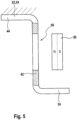
- Fig. 5 shows a sectional view through part of a sliding door device 1 according to a further embodiment, the sliding door 2 being here in an intermediate position between the closed position and the open position.
- the sliding door 2 for example, also carries the first permanent magnet 30.
- a local through opening 50 is formed in the wall, for example, of the second leg 42 of the carrier plate 24.
- the carrier plate 24 is in turn made of magnetically conductive material. Consequently, in the intermediate position, the first permanent magnet 30 approximately overlaps with this through opening 50, in which case the magnetic resistance is relatively large because the air in the through opening 50 has only a very low magnetic conductivity.
- a magnetic reluctance force 48 now arises, which attempts to pull the first permanent magnet 30 together with the sliding door 2 into areas with higher magnetic conductivity of the carrier plate 24. Therefore, the reluctance force 48 acts in the direction of displacement 8 towards the edge of the through opening 50 in the carrier plate 24 there. This is because a type of local or relative accumulation of magnetically conductive material is present in the areas of the carrier plate 24 adjacent to the through opening 50, which then have a greater magnetic conductivity than the through opening 50.
- the magnetic reluctance force 48 which acts on the sliding door 2 in the open position, is therefore based on a difference in the magnetic conductivity between a first section of the carrier plate 24 in the form of the unperforated wall ("local accumulation of magnetically conductive material") of the magnetic conductive material existing carrier plate 24 and a second section of the carrier plate 24 in the form of the through opening 50 ("local reduction of magnetically conductive material"), the first and second sections, seen in the displacement direction 8, arranged one behind the other in the open position of the sliding door and offset from one another are offset.
- the difference in magnetic conductivity between the first section (continuous wall) and the second section of the carrier plate (through opening) can generally be generated by a different volume, a different area and / or a different mass of magnetically conductive material.
- the magnetically conductive element 32 could also be rigidly attached to the door frame 6 or rigidly connected to these components in such a way that a magnetic reluctance force 48 is generated in the form of a magnetic attraction or repulsion force, which pulls or pushes the sliding door 2 into the open position or holds it in the open position.
- first permanent magnet 30 is statically connected to the sliding door 2 and the magnetically conductive element 32 to the door frame 6 or the door guide 22.
- the relationships can also be reversed.
- the first permanent magnet 30 and the magnetically conductive element 32 are then to be arranged as in a sliding door device in such a way that the magnetic reluctance force 48 acts in the phase of moving the pivoting sliding door in order to achieve the desired holding of the pivoting sliding door in the open position.
Claims (6)
- Dispositif de porte de véhicule (1), comprenant au moins les éléments suivants :a) au moins une porte coulissante (2) coulissant dans un sens de coulissement (8) par rapport à un cadre de porte (6) présentant une ouverture de porte (4) ou porte coulissante pivotante coulissant dans un sens de coulissement et pivotant dans un sens de pivotement,b) un dispositif d'entraînement, par lequel l'au moins une porte coulissante (2) ou porte coulissante pivotante est mobile dans une position de fermeture fermant l'ouverture de porte (4) et dans une position d'ouverture libérant l'ouverture de porte (4) ainsi que dans des positions intermédiaires quelconques entre la position de fermeture et la position d'ouverture,c) un guidage de porte (22, 24) pour le guidage de l'au moins une porte coulissante (2) ou porte coulissante pivotante par rapport à l'ouverture de porte (4),d) un dispositif magnétique (28) agissant sans courant qui contient au moins un premier aimant permanent (30) et au moins un élément (32) conducteur magnétiquement et qui exerce directement ou indirectement une force (48) magnétique générée sans action de courant électrique sur l'au moins une porte coulissante (2) ou porte coulissante pivotante de telle manière que l'au moins une porte coulissante (2) ou porte coulissante pivotanted1) soit poussée à partir d'une position intermédiaire dans la position d'ouverture, et/oud2) soit maintenue dans la position d'ouverture déjà occupée, dans lequel la force magnétique (48) agit comme force d'attraction magnétique entre l'au moins un premier aimant permanent (30) et l'au moins un élément (32) conducteur magnétiquement, caractérisé en ce que vu dans une direction perpendiculaire au plan de la porte coulissante (2) ou porte coulissante pivotante, l'au moins un premier aimant permanent (30) et l'au moins un élément (32) conducteur magnétiquement se recouvrent au moins partiellement dans la position d'ouverture, et que l'au moins un élément (32) conducteur magnétiquement se distingue d'un aimant permanent, et que l'au moins un premier aimant permanent (30) est relié respectivement statiquement à l'au moins une porte coulissante (2) ou porte coulissante pivotante et l'au moins un élément (32) conducteur magnétiquement au cadre de porte (6) ou au guidage de porte (22, 24), et que par rapport aux zones contiguës à l'au moins un élément (32) conducteur magnétiquement du cadre de porte (6) ou du guidage de porte (22, 24), l'au moins un élément (32) conducteur magnétiquement possède une conductivité magnétique supérieure en fonction du volume, de la surface et/ou de la masse de matériau conducteur magnétiquement ou l'au moins un premier aimant permanent (30) est relié respectivement statiquement au cadre de porte (6) ou guidage de porte (22, 24) et l'au moins un élément (32) conducteur magnétiquement à l'au moins une porte coulissante (2) ou porte coulissante pivotante, et que par rapport aux zones contiguës à l'au moins un élément (32) conducteur magnétiquement de la porte coulissante (2) ou porte coulissante pivotante, l'au moins un élément (32) conducteur magnétiquement possède une conductivité magnétique supérieure en fonction du volume, de la surface et/ou de la masse de matériau conducteur magnétiquement.
- Dispositif de porte de véhicule selon la revendication 1, caractérisé en ce qu'entre l'au moins un premier aimant permanent (30) et l'au moins un élément (32) conducteur magnétiquement, une fente d'air (d) est minimale lorsque l'au moins une porte coulissante (2) ou porte coulissante pivotante se trouve dans la position d'ouverture.
- Dispositif de porte de véhicule selon l'une quelconque des revendications précédentes, caractérisé en ceque l'au moins un élément (32) conducteur magnétiquement forme une accumulation locale de matériau conducteur magnétiquement.
- Dispositif de porte de véhicule selon l'une quelconque des revendications précédentes, caractérisé en ce que la force magnétique (48) est générée par l'interaction entre l'au moins un premier aimant permanent (30) et l'au moins un élément (32) conducteur magnétiquement se trouvant au moins dans la position d'ouverture dans le flux magnétique de l'au moins un premier aimant permanent (30).
- Dispositif de porte de véhicule selon l'une quelconque des revendications précédentes, caractérisé en ce que la force magnétique (48) est une force de réluctance magnétique qui agit entre l'au moins un premier aimant permanent (30) et l'au moins un élément (32) conducteur magnétiquement de telle manière que la résistance magnétique du flux magnétique soit réduite ou minimale entre l'au moins un premier aimant permanent (30) et l'au moins un élément (32) conducteur magnétiquement lorsque l'au moins une porte coulissante (2) ou porte coulissante pivotante se trouve dans la position d'ouverture.
- Véhicule, en particulier véhicule ferroviaire avec au moins un dispositif de porte de véhicule (1) selon l'une quelconque des revendications précédentes.
Applications Claiming Priority (2)
| Application Number | Priority Date | Filing Date | Title |
|---|---|---|---|
| DE102019003808.8A DE102019003808A1 (de) | 2019-05-31 | 2019-05-31 | Fahrzeugtürvorrichtung mit stromloser Offenhaltefunktion |
| PCT/EP2020/063790 WO2020239492A1 (fr) | 2019-05-31 | 2020-05-18 | Dispositif de porte de véhicule à fonction de maintien en position d'ouverture non électrique |
Publications (2)
| Publication Number | Publication Date |
|---|---|
| EP3976916A1 EP3976916A1 (fr) | 2022-04-06 |
| EP3976916B1 true EP3976916B1 (fr) | 2024-03-20 |
Family
ID=70847338
Family Applications (1)
| Application Number | Title | Priority Date | Filing Date |
|---|---|---|---|
| EP20727948.0A Active EP3976916B1 (fr) | 2019-05-31 | 2020-05-18 | Dispositif de porte de véhicule à fonction de maintien en position d'ouverture non électrique |
Country Status (3)
| Country | Link |
|---|---|
| EP (1) | EP3976916B1 (fr) |
| DE (1) | DE102019003808A1 (fr) |
| WO (1) | WO2020239492A1 (fr) |
Family Cites Families (5)
| Publication number | Priority date | Publication date | Assignee | Title |
|---|---|---|---|---|
| DE202006017402U1 (de) * | 2006-11-15 | 2006-12-28 | BLASI - GMBH Automatische Türanlagen | Schiebetür |
| FR2960899A1 (fr) * | 2010-06-08 | 2011-12-09 | Jacques Afriat | Systeme de controle du mouvement d’une porte coulissante, notamment d’une porte de placard |
| EP3161236B1 (fr) * | 2014-06-27 | 2019-01-30 | Tofas Turk Otomobil Fabrikasi Anonim Sirketi | Système de porte coulissante |
| DE102015210593B3 (de) * | 2015-06-10 | 2016-06-16 | Siemens Aktiengesellschaft | Vorrichtung zum Halten und/oder Bremsen einer Tür |
| WO2017123908A1 (fr) * | 2016-01-14 | 2017-07-20 | Pemko Manufacturing Company, Inc. | Dispositif et système d'arrêt en douceur |
-
2019
- 2019-05-31 DE DE102019003808.8A patent/DE102019003808A1/de active Pending
-
2020
- 2020-05-18 WO PCT/EP2020/063790 patent/WO2020239492A1/fr unknown
- 2020-05-18 EP EP20727948.0A patent/EP3976916B1/fr active Active
Also Published As
| Publication number | Publication date |
|---|---|
| DE102019003808A1 (de) | 2020-12-03 |
| WO2020239492A1 (fr) | 2020-12-03 |
| EP3976916A1 (fr) | 2022-04-06 |
Similar Documents
| Publication | Publication Date | Title |
|---|---|---|
| EP0498247B1 (fr) | Dispositif pour l'entraînement et de déverrouillage des portes d'une cage d'ascenseur | |
| EP3775463B1 (fr) | Porte avec dispositif de guidage | |
| EP2297421A1 (fr) | Mécanisme d'entraînement de porte | |
| EP3715570B1 (fr) | Installation de porte coulissante | |
| WO2011020557A1 (fr) | Glissière pour une paroi coulissante et procédé pour actionner une aiguille dans une glissière | |
| EP3976911B1 (fr) | Dispositif de porte de véhicule à fonction d'ouverture sans courant | |
| DE102006040070A1 (de) | Fahrzeug mit einer Schiebetüre | |
| DE19835678C2 (de) | Elektrisch betätigbare Verriegelungseinrichtung für Türflügel, insbesondere Schiebetürflügel | |
| EP3976916B1 (fr) | Dispositif de porte de véhicule à fonction de maintien en position d'ouverture non électrique | |
| DE10257673B4 (de) | Verschlussvorrichtung einer in der Karosserie eines Fahrzeuges vorgesehenen Öffnung, und entsprechendes Fahrzeug | |
| DE102016210168B3 (de) | Türantrieb für eine Kraftwagentür | |
| DE102008012854A1 (de) | Schiebetüranordnung eines Kraftfahrzeugs | |
| EP2165868A1 (fr) | Système de porte coulissante pivotante | |
| EP1681426A2 (fr) | Porte coulissante avec système d'entraînement magnétique et portes s'ouvrant individuellement et leur procédé de commande | |
| EP3656958B1 (fr) | Entraînement auxiliaire pourvu de dispositif d'amortissement pour un battant de portail motorisée ainsi que portail, dont battant de portail est équipé d'un entraînement auxiliaire contenant un dispositif d'amortissement | |
| DE102018123345B4 (de) | Antriebsvorrichtung für elektrische Türen | |
| WO2020239557A1 (fr) | Système de porte de véhicule à fonction de freinage | |
| DE202020101360U1 (de) | Tor mit Führungsanordnung | |
| DE102005015797B4 (de) | Sicherheitsschalter, insbesondere für Schutzschranken | |
| DE202008013553U1 (de) | Beschlag für einen Flügel von Fenstern oder Türen | |
| DE2040790A1 (de) | Zellentuer-Betaetigungsvorrichtung | |
| DE102018115798A1 (de) | Türantrieb für den Antrieb einer Schiebetür eines Fahrzeugs | |
| DE202016007175U1 (de) | Vorrichtung zum Öffnen und Schließen eines Flügels | |
| DE102008011735A1 (de) | Schiebetüranordnung eines Kraftfahrzeugs | |
| DE19638741A1 (de) | Elektromechanischer Antrieb für eine Schiebetür |
Legal Events
| Date | Code | Title | Description |
|---|---|---|---|
| STAA | Information on the status of an ep patent application or granted ep patent |
Free format text: STATUS: UNKNOWN |
|
| STAA | Information on the status of an ep patent application or granted ep patent |
Free format text: STATUS: THE INTERNATIONAL PUBLICATION HAS BEEN MADE |
|
| PUAI | Public reference made under article 153(3) epc to a published international application that has entered the european phase |
Free format text: ORIGINAL CODE: 0009012 |
|
| STAA | Information on the status of an ep patent application or granted ep patent |
Free format text: STATUS: REQUEST FOR EXAMINATION WAS MADE |
|
| 17P | Request for examination filed |
Effective date: 20220103 |
|
| AK | Designated contracting states |
Kind code of ref document: A1 Designated state(s): AL AT BE BG CH CY CZ DE DK EE ES FI FR GB GR HR HU IE IS IT LI LT LU LV MC MK MT NL NO PL PT RO RS SE SI SK SM TR |
|
| DAV | Request for validation of the european patent (deleted) | ||
| DAX | Request for extension of the european patent (deleted) | ||
| STAA | Information on the status of an ep patent application or granted ep patent |
Free format text: STATUS: EXAMINATION IS IN PROGRESS |
|
| 17Q | First examination report despatched |
Effective date: 20230216 |
|
| REG | Reference to a national code |
Ref document number: 502020007417 Country of ref document: DE Ref country code: DE Ref legal event code: R079 Free format text: PREVIOUS MAIN CLASS: E05D0015060000 Ipc: E05C0019160000 |
|
| RIC1 | Information provided on ipc code assigned before grant |
Ipc: E05C 19/16 20060101AFI20230914BHEP |
|
| GRAP | Despatch of communication of intention to grant a patent |
Free format text: ORIGINAL CODE: EPIDOSNIGR1 |
|
| STAA | Information on the status of an ep patent application or granted ep patent |
Free format text: STATUS: GRANT OF PATENT IS INTENDED |
|
| INTG | Intention to grant announced |
Effective date: 20231026 |
|
| GRAS | Grant fee paid |
Free format text: ORIGINAL CODE: EPIDOSNIGR3 |
|
| GRAA | (expected) grant |
Free format text: ORIGINAL CODE: 0009210 |
|
| STAA | Information on the status of an ep patent application or granted ep patent |
Free format text: STATUS: THE PATENT HAS BEEN GRANTED |
|
| AK | Designated contracting states |
Kind code of ref document: B1 Designated state(s): AL AT BE BG CH CY CZ DE DK EE ES FI FR GB GR HR HU IE IS IT LI LT LU LV MC MK MT NL NO PL PT RO RS SE SI SK SM TR |
|
| REG | Reference to a national code |
Ref country code: GB Ref legal event code: FG4D Free format text: NOT ENGLISH |
|
| REG | Reference to a national code |
Ref country code: CH Ref legal event code: EP |
|
| REG | Reference to a national code |
Ref country code: DE Ref legal event code: R096 Ref document number: 502020007417 Country of ref document: DE |