EP3974639B1 - Brennkraftmaschine und stromerzeugungssystem - Google Patents
Brennkraftmaschine und stromerzeugungssystem Download PDFInfo
- Publication number
- EP3974639B1 EP3974639B1 EP19940939.2A EP19940939A EP3974639B1 EP 3974639 B1 EP3974639 B1 EP 3974639B1 EP 19940939 A EP19940939 A EP 19940939A EP 3974639 B1 EP3974639 B1 EP 3974639B1
- Authority
- EP
- European Patent Office
- Prior art keywords
- terminal
- resistor
- amplifier
- internal combustion
- combustion engine
- Prior art date
- Legal status (The legal status is an assumption and is not a legal conclusion. Google has not performed a legal analysis and makes no representation as to the accuracy of the status listed.)
- Active
Links
Images


Classifications
-
- F—MECHANICAL ENGINEERING; LIGHTING; HEATING; WEAPONS; BLASTING
- F02—COMBUSTION ENGINES; HOT-GAS OR COMBUSTION-PRODUCT ENGINE PLANTS
- F02D—CONTROLLING COMBUSTION ENGINES
- F02D41/00—Electrical control of supply of combustible mixture or its constituents
- F02D41/24—Electrical control of supply of combustible mixture or its constituents characterised by the use of digital means
- F02D41/26—Electrical control of supply of combustible mixture or its constituents characterised by the use of digital means using computer, e.g. microprocessor
- F02D41/28—Interface circuits
-
- F—MECHANICAL ENGINEERING; LIGHTING; HEATING; WEAPONS; BLASTING
- F02—COMBUSTION ENGINES; HOT-GAS OR COMBUSTION-PRODUCT ENGINE PLANTS
- F02B—INTERNAL-COMBUSTION PISTON ENGINES; COMBUSTION ENGINES IN GENERAL
- F02B63/00—Adaptations of engines for driving pumps, hand-held tools or electric generators; Portable combinations of engines with engine-driven devices
- F02B63/04—Adaptations of engines for driving pumps, hand-held tools or electric generators; Portable combinations of engines with engine-driven devices for electric generators
-
- F—MECHANICAL ENGINEERING; LIGHTING; HEATING; WEAPONS; BLASTING
- F02—COMBUSTION ENGINES; HOT-GAS OR COMBUSTION-PRODUCT ENGINE PLANTS
- F02D—CONTROLLING COMBUSTION ENGINES
- F02D33/00—Controlling delivery of fuel or combustion-air, not otherwise provided for
-
- F—MECHANICAL ENGINEERING; LIGHTING; HEATING; WEAPONS; BLASTING
- F02—COMBUSTION ENGINES; HOT-GAS OR COMBUSTION-PRODUCT ENGINE PLANTS
- F02D—CONTROLLING COMBUSTION ENGINES
- F02D35/00—Controlling engines, dependent on conditions exterior or interior to engines, not otherwise provided for
- F02D35/02—Controlling engines, dependent on conditions exterior or interior to engines, not otherwise provided for on interior conditions
- F02D35/027—Controlling engines, dependent on conditions exterior or interior to engines, not otherwise provided for on interior conditions using knock sensors
-
- F—MECHANICAL ENGINEERING; LIGHTING; HEATING; WEAPONS; BLASTING
- F02—COMBUSTION ENGINES; HOT-GAS OR COMBUSTION-PRODUCT ENGINE PLANTS
- F02P—IGNITION, OTHER THAN COMPRESSION IGNITION, FOR INTERNAL-COMBUSTION ENGINES; TESTING OF IGNITION TIMING IN COMPRESSION-IGNITION ENGINES
- F02P5/00—Advancing or retarding ignition; Control therefor
- F02P5/04—Advancing or retarding ignition; Control therefor automatically, as a function of the working conditions of the engine or vehicle or of the atmospheric conditions
- F02P5/145—Advancing or retarding ignition; Control therefor automatically, as a function of the working conditions of the engine or vehicle or of the atmospheric conditions using electrical means
- F02P5/15—Digital data processing
- F02P5/152—Digital data processing dependent on pinking
-
- G—PHYSICS
- G01—MEASURING; TESTING
- G01M—TESTING STATIC OR DYNAMIC BALANCE OF MACHINES OR STRUCTURES; TESTING OF STRUCTURES OR APPARATUS, NOT OTHERWISE PROVIDED FOR
- G01M15/00—Testing of engines
- G01M15/04—Testing internal-combustion engines
- G01M15/11—Testing internal-combustion engines by detecting misfire
-
- F—MECHANICAL ENGINEERING; LIGHTING; HEATING; WEAPONS; BLASTING
- F02—COMBUSTION ENGINES; HOT-GAS OR COMBUSTION-PRODUCT ENGINE PLANTS
- F02D—CONTROLLING COMBUSTION ENGINES
- F02D41/00—Electrical control of supply of combustible mixture or its constituents
- F02D41/24—Electrical control of supply of combustible mixture or its constituents characterised by the use of digital means
- F02D41/26—Electrical control of supply of combustible mixture or its constituents characterised by the use of digital means using computer, e.g. microprocessor
- F02D41/28—Interface circuits
- F02D2041/281—Interface circuits between sensors and control unit
-
- F—MECHANICAL ENGINEERING; LIGHTING; HEATING; WEAPONS; BLASTING
- F02—COMBUSTION ENGINES; HOT-GAS OR COMBUSTION-PRODUCT ENGINE PLANTS
- F02D—CONTROLLING COMBUSTION ENGINES
- F02D29/00—Controlling engines, such controlling being peculiar to the devices driven thereby, the devices being other than parts or accessories essential to engine operation, e.g. controlling of engines by signals external thereto
- F02D29/06—Controlling engines, such controlling being peculiar to the devices driven thereby, the devices being other than parts or accessories essential to engine operation, e.g. controlling of engines by signals external thereto peculiar to engines driving electric generators
Definitions
- the present invention relates to an internal combustion engine and a power generation system.
- Sensors are used in various systems. In order for a sensor to correctly detect a target physical quantity, it is necessary to reduce influence from the measuring environment such as wiring and noise.
- Patent Document 1 describes, as an associated technique, a technique related to a vortex flow meter that takes the difference between the outputs of two charge amplification circuits and cancels common mode noise applied to one piezoelectric element. Another example is shown in US 2009/120164 A1 .
- Patent Document 1 JP 3478375 B
- internal combustion engines used as a power source for generators in power generation systems that generate power are often provided with a plurality of cylinders (i.e., multi-cylinder).
- ignition timing is controlled to control combustion.
- a phenomenon called knocking sometimes occurs when, for example, air inside the cylinder is compressed more strongly than normal, which then causes the intake air to reach a high temperature and triggers spontaneous combustion, with combustion occurring at a timing different from the ignition timing. If knocking occurs, the cylinder vibrates.
- a sensor that detects vibration of the cylinder called knock sensor, is provided on each cylinder to detect knocking.
- the output signal of a knock sensor is a differential output, it is susceptible to common mode noise.
- the output signal of a knock sensor is simply converted to a voltage, if the wiring length for transmitting the voltage is long, it is susceptible to voltage variation due to wiring length.
- the wiring lengths for transmitting voltages are non-uniform among knock sensors, even if the cylinders vibrate approximately equally, each knock sensor may detect a different vibration due to influence from these non-uniform wiring lengths.
- An object of the present invention is to provide an internal combustion engine and a power generation system that can solve the above problems.
- an internal combustion engine includes an internal combustion engine main body including a plurality of cylinders, a knock sensor provided on each of the plurality of cylinders, a control board including an amplification circuit, and a plurality of cables differing in length and each connecting the knock sensor and the control board.
- the amplification circuit includes, for each of the plurality of cables, a first charge amplifier connected to a first output terminal of the knock sensor via one of the plurality of cables, a second charge amplifier connected to a second output terminal of the knock sensor via one of the plurality of cables, and a differential amplifier configured to take an output of the first charge amplifier and an output of the second charge amplifier as input.
- the amplification circuit includes a bandpass filter configured to allow a frequency band of an output of the differential amplifier to pass through.
- control board includes a determination unit configured to determine whether knocking has occurred on the basis of an output signal of the amplification circuit.
- the determination unit may be configured to determine, if it is determined that an amplitude of the output signal of the amplification circuit is not greater than a threshold value of amplitude for determining that knocking has occurred, that no knocking has occurred, and the determination unit may be configured to determine, if it is determined that the amplitude of the output signal of the amplification circuit exceeds the threshold value, that knocking is occurring.
- control board may include a correction unit configured to correct, if it is determined that knocking is occurring, an ignition timing of fuel in the internal combustion engine main body or an amount of fuel supplied to the internal combustion engine main body.
- a power generation system includes the internal combustion engine according to any one of the first to third aspects, and a generator configured to generate power, with energy generated by the internal combustion engine serving as a power source.
- FIG. 1 is a diagram illustrating the configuration of a power generation system 1 according to an embodiment of the present invention.
- the power generation system 1 includes an internal combustion engine 10 and a generator 20.
- the power generation system 1 is a system that generates power by rotating the generator 20, with energy obtained by combustion in an internal combustion engine 10 serving as a power source.
- the internal combustion engine 10 includes an internal combustion engine main body 101, a control board 102, and cables 103a1, 103a2, ..., and 103an.
- the cables 103a1, 103a2, ..., and 103an are collectively referred to as cable 103 or cables 103.
- the internal combustion engine main body 101 includes cylinders (cylinders) 1011a1, 1011a2, ..., and 1011an, and knock sensors 1012a1, 1012a2, ..., and 1012an.
- the cylinders 1011a1, 1011a2, ..., and 1011an are collectively referred to as cylinder 1011 or cylinders 1011.
- the knock sensors 1012a1, 1012a2, ..., and 1012an are collectively referred to as knock sensor 1012 or knock sensors 1012.
- gas is combusted in each cylinder 1011 to move the piston (not illustrated) up and down within each cylinder 1011 and rotate the crank shaft (not illustrated), for example, thereby obtaining rotational energy.
- the knock sensor 1012 is a sensor configured to detect knocking in the cylinder 1011. Knocking is the occurrence of abnormal vibration in the cylinder 1011. The following describes conceivable causes of knocking. If air inside the cylinder 1011 is compressed more strongly than normal by the gas fuel, then the intake air reaches a high temperature, spontaneous combustion is triggered, and this spontaneous combustion causes the gas to start combustion earlier than the proper ignition timing of the engine.
- the knock sensor 1012 is provided on each cylinder 1011 to detect vibration in the cylinder 1011. Specifically, the knock sensor 1012a1 is provided on the cylinder 1011a1 to detect vibration in the cylinder 1011a. The knock sensor 1012a2 is also provided on the cylinder 1011a2 to detect vibration in the cylinder 1011a2. The knock sensor 1012an is also provided on the cylinder 1011an to detect vibration in the cylinder 1011an. The knock sensor 1012 has a first output terminal and a second output. An electrical signal having a charge amount corresponding to a magnitude of the detected vibration is outputted from the first output terminal and the second output terminal.
- the charge amount outputted from the first output terminal and the charge amount outputted from the second output terminal are equal charge amounts falling within an error range.
- the charge amount outputted from the second output terminal is small if the charge amount outputted from the first output terminal is large, and the charge amount outputted from the second output terminal is large if the charge amount outputted from the first output terminal is small. That is, the charge amount outputted from the first output terminal and the charge amount outputted from the second output terminal are inversely increased or decreased with respect to each other, with the charge amount outputted when no vibration is detected serving as a reference.
- the control board 102 is a control board configured to amplify the electrical signal outputted from the knock sensor 1012 and control the operation of the internal combustion engine main body 101 on the basis of the amplified signal.
- the control board 102 includes amplification circuits 1021a1, 1021a2, ..., and 1021an, and a control circuit 1022 (an example of a determination unit and an example of a correction unit).
- the amplification circuits 1021a1, 1021a2, ..., and 1021an are collectively referred to as amplification circuit 1021 or amplification circuits 1021.
- each amplification circuit 1021 includes a first charge amplifier 110, a second charge amplifier 120, a differential amplifier 130, a gain amplifier 140, and a bandpass filter 150.
- the first charge amplifier 110 includes an operational amplifier 1101, resistors 1102 and 1103, and a capacitor 1104.
- a first terminal of the resistor 1102 is connected to a non-inverting input terminal of the operational amplifier 1101.
- a first output terminal of the knock sensor 1012, a first terminal of the resistor 1103, and a first terminal of the capacitor 1104 are connected to an inverting input terminal of the operational amplifier 1101.
- a second terminal of the resistor 1103 and a second terminal of the capacitor 1104 are connected to an output terminal of the operational amplifier 1101.
- a second terminal of the resistor 1102 is connected to the ground GND.
- the first charge amplifier 110 is a circuit configured to output a signal proportional to the total charge amount inputted (the integrated value of the current).
- the first charge amplifier 110 receives the electrical signal outputted from the first output terminal of the knock sensor 1012 at the inverting input terminal via the cable 103.
- the first charge amplifier 110 converts the received electrical signal into a signal proportional to the total charge amount by an integration circuit consisting of the resistor 1103 and the capacitor 1104. At this time, the first charge amplifier 110 can convert the received electrical signal into a signal proportional to the total charge amount without depending on the length of the cable 103.
- the first charge amplifier 110 outputs the converted signal to the differential amplifier 130.
- the second charge amplifier 120 includes an operational amplifier 1201, resistors 1202 and 1203, and a capacitor 1204.
- a first terminal of the resistor 1202 is connected to a non-inverting input terminal of the operational amplifier 1201.
- a second output terminal of the knock sensor 1012, a first terminal of the resistor 1203, and a first terminal of the capacitor 1204 are connected to an inverting input terminal of the operational amplifier 1201.
- a second terminal of the resistor 1203 and a second terminal of the capacitor 1204 are connected to an output terminal of the operational amplifier 1201.
- a second terminal of the resistor 1202 is connected to the ground GND.
- the second charge amplifier 120 is a circuit configured to output a signal proportional to the total charge amount inputted (the integrated value of the current).
- the second charge amplifier 120 receives an electrical signal outputted from the second output terminal of the knock sensor 1012 at the inverting input terminal via the cable 103.
- the second charge amplifier 120 converts the received electrical signal into a signal proportional to the total charge amount by an integration circuit consisting of the resistor 1203 and the capacitor 1204. At this time, the second charge amplifier 120 converts the received electrical signal into a signal proportional to the total charge amount without depending on the length of the cable 103.
- the second charge amplifier 120 outputs the converted signal to the differential amplifier 130.
- the differential amplifier 130 includes an operational amplifier 1301 and resistors 1302, 1303, 1304, and 1305.
- a first terminal of the resistor 1302 and a first terminal of the resistor 1303 are connected to a non-inverting input terminal of the operational amplifier 1301.
- a first terminal of the resistor 1304 and a first terminal of the resistor 1305 are connected to an inverting input terminal of the operational amplifier 1301.
- a second terminal of the resistor 1305 is connected to an output terminal of the operational amplifier 1301.
- a second terminal of the resistor 1302 is connected to the output terminal of the first charge amplifier 110.
- a second terminal of the resistor 1303 is connected to the ground GND.
- a second terminal of the resistor 1304 is connected to the output terminal of the second charge amplifier 120.
- the differential amplifier 130 With the output of the first charge amplifier 110 and the output of the second charge amplifier 120 serving as a differential input signal, the differential amplifier 130 amplifies the differential input signal and outputs the amplified signal to the gain amplifier 140. The differential amplifier 130 amplifies the differential input signal. This differential amplifier 130 improves a common-mode rejection ratio (CMRR).
- CMRR common-mode rejection ratio
- the resistance value of the resistor 1302 is made approximately equal to the resistance value of the resistor 1304. Also, the resistance value of the resistor 1303 is made approximately equal to the resistance value of the resistor 1305. Additionally, the resistance value of each of the resistors 1302, 1303, 1304, and 1305 is a fixed value.
- the gain amplifier 140 includes an operational amplifier 1401 and resistors 1402, 1403, and 1404.
- a first terminal of the resistor 1402 is connected to a non-inverting input terminal of the operational amplifier 1401.
- a first terminal of the resistor 1403 and a first terminal of the resistor 1404 are connected to an inverting input terminal of the operational amplifier 1401.
- a second terminal of the resistor 1403 is connected to an output terminal of the operational amplifier 1401.
- a second terminal of the resistor 1402 is connected to the ground GND.
- a second terminal of the resistor 1404 is connected to an output terminal of the differential amplifier 130.
- the gain amplifier 140 amplifies the output signal of the amplification circuit 1021 such that the amplitude of the output signal of the amplification circuit 1021 comes to the desired amplitude corresponding to the magnitude of the electrical signal outputted by the knock sensor 1012.
- the gain amplifier 140 outputs the amplified signal to the bandpass filter 150.
- the bandpass filter 150 allows only signals of a predetermined frequency component to pass through.
- a predetermined frequency component means a signal component indicating a frequency that is contained in an electrical signal outputted by the knock sensor 1012.
- the bandpass filter 150 receives an output signal outputted from the gain amplifier 140, out of the received signals, allows only a signal having a frequency component that needs to pass through the bandpass filter 15 to pass through, and outputs the signal that has passed through to the control circuit 1022.
- the control circuit 1022 receives a signal of a predetermined frequency component from each amplification circuit 1021.
- the control circuit 1022 compares the amplitude of the signal received from each amplification circuit 1021 with a threshold value.
- This threshold value is an amplitude value determined by the amplitude of the electrical signal outputted from the knock sensor 1012 when knocking has occurred, that is, when the cylinder 1011 vibrates, and is an amplitude value for determining whether knocking has occurred.
- the control circuit 1022 determines that no knocking is occurring in the internal combustion engine main body 101.
- the control circuit 1022 determines that knocking has occurred in the cylinder 1011 corresponding to the signal. If it is determined that knocking has occurred in the cylinder 1011, the control circuit 1022 prevents the occurrence of knocking by performing control to correct the ignition timing of the gas, or performing control to correct the amount of gas fuel supplied to the internal combustion engine main body 101.
- the generator 20 generates power by rotating, with energy generated by the internal combustion engine 10 serving as a power source.
- the processing of the power generation system 1 is described in the following by using a case in which the output signal of the knock sensor 1012a1 provided on the cylinder 1011a1 is detected as an example, the processing for the knock sensor 1012 provided on each cylinder 1011 is also performed in the same manner as that for the knock sensor 1012a1 provided on the cylinder 1011a1.
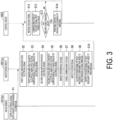
- the knock sensor 1012a1 detects vibration of the cylinder 1011a1 and outputs an electrical signal with a charge amount corresponding to the vibration to the amplification circuit 1021a1 (step S1). For example, if no knocking is occurring in the cylinder 1011a1, the knock sensor 1012a1 outputs electrical signals with an approximately equal charge amount from the first output terminal and the second output terminal. In addition, when knocking has occurred in the cylinder 1011a1, the knock sensor 1012a1 outputs electrical signals from the first output terminal and the second output terminal that are inversely increased or decreased with respect to each other, with the charge amount outputted from the first output terminal and the charge amount outputted from the second output terminal when no knocking is occurring serving as a reference.
- the knock sensor 1012a1 when knocking has occurred, the knock sensor 1012a1 outputs from the first output terminal an electrical signal with great charge compared to when no knocking is occurring, and outputs from the second output terminal an electrical signal with less charge compared to when no knocking is occurring.
- the knock sensor 1012a1 when knocking has occurred, the knock sensor 1012a1 outputs from the first output terminal an electrical signal with less charge compared to when no knocking is occurring, and outputs from the second output terminal an electrical signal with great charge compared to when no knocking is occurring.
- the first charge amplifier 110 receives an electrical signal from the knock sensor 1012a1 (step S2).
- the first charge amplifier 110 stores the charge of the received electrical signal in the capacitor 1104, thereby converting it into a voltage having a magnitude corresponding to the charge amount of the electrical signal (step S3).
- the first charge amplifier 110 outputs a voltage having a magnitude corresponding to the charge amount of the electrical signal to the differential amplifier 130. Note that in a case where an electrical signal with great charge compared to the charge of when no knocking is occurring is received, for example, the first charge amplifier 110 outputs a low voltage compared to the voltage outputted when no knocking is occurring. In addition, in a case where an electrical signal with less charge compared to the charge of when no knocking is occurring is received, for example, the first charge amplifier 110 outputs a high voltage compared to the voltage outputted when no knocking is occurring.
- the second charge amplifier 120 also receives an electrical signal from the knock sensor 1012a1 (step S4).
- the second charge amplifier 120 stores the charge of the received electrical signal in the capacitor 1204, thereby converting it into a voltage having a magnitude corresponding to the charge amount of the electrical signal (step S5).
- the second charge amplifier 120 outputs a voltage having a magnitude corresponding to the charge amount of the electrical signal to the differential amplifier 130. Note that in a case where an electrical signal with less charge compared to the charge of when no knocking is occurring is received, for example, the second charge amplifier 120 outputs a high voltage compared to the voltage outputted when no knocking is occurring. In addition, in a case where an electrical signal with great charge compared to the charge of when no knocking is occurring is received, for example, the second charge amplifier 120 outputs a low voltage compared to the voltage outputted when no knocking is occurring.
- the first charge amplifier 110 and the second charge amplifier 120 convert the charge amount of an electrical signal outputted by the knock sensor 1012a1 into a voltage.
- the first charge amplifier 110 and the second charge amplifier 120 can output a voltage corresponding to the charge of the electrical signal outputted by the knock sensor 1012a1.
- the differential amplifier 130 receives signals with different voltages from the first charge amplifier 110 and the second charge amplifier 120.
- the differential amplifier 130 amplifies the differential voltage between the voltage received from the first charge amplifier 110 and the voltage received from the second charge amplifier 120 (step S6). Furthermore, at this time, the differential amplifier 130 cancels the common mode voltage (voltage of the in-phase component) contained in the voltage received from the first charge amplifier 110 and the voltage received from the second charge amplifier 120 (step S7).
- the differential amplifier 130 outputs the amplified voltage to the gain amplifier 140.
- the differential amplifier 130 when the output signal of the first charge amplifier 110 and the output signal of the second charge amplifier 120 are approximately equal, that is, when the signals inputted to the differential input terminals of the differential amplifier 130 are approximately equal, then the differential amplifier 130 outputs a signal approximately equal to the output signal of when no knocking is occurring, which is determined by the bias.
- the differential amplifier 130 when the voltage received from the first charge amplifier 110 is greater than the voltage received from the second charge amplifier 120, the differential amplifier 130 outputs a signal of a greater voltage than the voltage outputted when no knocking is occurring.
- the differential amplifier 130 when the voltage received from the first charge amplifier 110 is less than the voltage received from the second charge amplifier 120, the differential amplifier 130 outputs a voltage signal of a less voltage than the voltage outputted when no knocking is occurring.
- the gain amplifier 140 receives a voltage signal from the differential amplifier 130.
- the gain amplifier 140 amplifies the received voltage signal (step S8).
- the gain amplifier 140 outputs the amplified voltage signal to the bandpass filter 150.
- the bandpass filter 150 receives a voltage signal from the gain amplifier 140. Out of the received voltage signals, the bandpass filter 150 allows a voltage signal having only a predetermined frequency component that needs to pass through to pass through (step S9) and outputs the voltage signal having only the frequency component to the control circuit 1022 (step S10).
- the output signal of the differential amplifier 130 is a signal approximately equal to the output signal of when no knocking is occurring, which is determined by the bias
- the output signal of the amplification circuit 1021a1 outputted via the gain amplifier 140 and the bandpass filter 150 is a signal approximately equal to the output signal of the amplification circuit 1021a1 of when no knocking is occurring, which is determined by the bias. That is, when no knocking is occurring in the cylinder 1011a1, the output signal of the amplification circuit 1021a1 is a signal approximately equal to the output signal of the amplification circuit 1021a1 of when no knocking is occurring, which is determined by the bias.
- the control circuit 1022 receives a voltage signal having a predetermined frequency component from the amplification circuit 1021a1 (step S11).
- the control circuit 1022 compares the amplitude of the received voltage signal with a threshold value (step S12).
- This threshold value is an amplitude value determined by the amplitude of the electrical signal outputted by the knock sensor 1012 when knocking has occurred, that is, when the cylinder 1011 vibrates, and is an amplitude value for determining whether knocking has occurred.
- the control circuit 1022 determines whether the amplitude of a signal received from the amplification circuit 1021 is not greater than the threshold value (step S13).
- the control circuit 1022 determines that knocking has occurred in the cylinder 1011 corresponding to the signal. If it is determined that knocking has occurred in the cylinder 1011, the control circuit 1022 performs control to prevent the occurrence of knocking by controlling the ignition timing of the gas, or by controlling the amount of gas fuel supplied to the internal combustion engine main body 101 and the like (step S14). Then, the processing in the control circuit 1022 returns to the processing of step S11.
- the power generation system 1 according to an embodiment of the present invention has been described above.
- the internal combustion engine 10 includes the internal combustion engine main body 101 including the plurality of cylinders 1011 (cylinders); the control board 102 configured to control the operation of the internal combustion engine main body 101; the knock sensor 1012 provided on each of the plurality of cylinders 1011; and the plurality of cables 103 differing in length and each connecting the knock sensor 1012 and the control board 102.
- the control board 102 includes, for each of the plurality of cables 103, the first charge amplifier 110 connected to the first output terminal of the knock sensor 1012 via one of the plurality of cables 103; the second charge amplifier 120 connected to the second output terminal of the knock sensors 1012 via one of the plurality of cables 103; and the differential amplifier 130 configured to take an output of the first charge amplifier 110 and an output of the second charge amplifier 120 as input.
- the output signal of the knock sensor is susceptible to influence from the measuring environment such as noise and wiring.
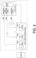
- the lengths of the cables 100 which are the wires from the knock sensors 1012 provided on each cylinder 1011 to the amplification circuits configured to amplify the output signals of the knock sensors 1012, need to be made approximately equal as illustrated in FIG. 4 .
- the first charge amplifier 110 and the second charge amplifier 120 in the power generation system 1 convert a charge amount of an electrical signal outputted by the knock sensor 1012a1, after the charge has moved via the cable 103, to a voltage.
- the first charge amplifier 110 and the second charge amplifier 120 can output a voltage corresponding to the charge amount of the electrical signal outputted by the knock sensor 1012a1.
- the differential amplifier 130 cancels the common mode voltage (voltage of the in-phase component) contained in the voltage received from the first charge amplifier 110 and the voltage received from the second charge amplifier 120.
- the internal combustion engine 10 can reduce noise from the cables 103 (wires), which are greatly affected by the measuring environment, and the in-phase component. Also, when each knock sensor 1012 detects an approximately equal vibration, the internal combustion engine 10 can detect them as approximately equal output signals (i.e., it is possible to reduce variation in detection among the respective knock sensors 1012). Note that, in the comparative power generation system, it is necessary to normalize the length of the cables 100 to six meters, which is the longest length among the cables. In contrast, in the power generation system 1 according to an embodiment of the present invention illustrated in FIG. 1 , it has been experimentally confirmed that it is possible to detect the outputs of the knock sensors 1012 even when the cables 103a1 to 103an that are non-uniform in length and from three to six meters are used.
- the internal combustion engine 10 can correctly detect the vibration to be detected by the knock sensors 1012, that is, the output signals of the knock sensors 1012, both in a case where the lengths of the cables 103 are non-uniform and in a case where the lengths of the cables 103 are approximately equal.
- the internal combustion engine 10 includes the bandpass filter 150.
- the internal combustion engine 10 can remove signals in the frequency bands outside the output signals of the knock sensor 1012, which serve as noise for the output signal of the knock sensor 1012.
- the internal combustion engine 10 can more correctly detect the vibration to be detected by the knock sensors 1012, that is, the output signals of the knock sensors 1012, compared to a case where the bandpass filter 150 is not included.
- a storage unit, other storage device, and the like in each embodiment of the present invention may be provided anywhere as long as information is transmitted and received appropriately.
- storage units, other storage devices, and the like may exist and store data in a distributed manner as long as information is transmitted and received appropriately.
- step S4 is performed earlier than that of step S2.
- control circuit 1022 and other control devices may include a computer system therein.
- the processes described above are stored in a computer-readable recording medium in the form of a program, and the processes are performed by a computer reading and executing the program.
- a specific example of the computer is illustrated below.
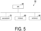
- FIG. 5 is a schematic block diagram for illustrating the configuration of a computer in at least one of the embodiments.
- a computer 50 includes a CPU 60, a main memory 70, a storage 80, and an interface 90.
- control circuit 1022 and other control devices are each implemented in the computer 50.
- operation of each processing unit described above is stored in the storage 80 in the form of a program.
- the CPU 60 reads a program from the storage 80, stores the program in the main memory 70, and executes the above-described processing in accordance with the program.
- the CPU 60 secures a storage area corresponding to each storage unit described above in the main memory 70 according to the program.
- Examples of the storage 80 include a hard disk drive (HDD), a solid state drive (SSD), a magnetic disk, a magneto-optical disk, a compact disc read only memory (CD-ROM), a digital versatile disc read only memory (DVD-ROM), and a semiconductor memory.
- the storage 80 may be an internal medium directly connected to the bus of the computer 50 or an external medium connected to the computer 50 via the interface 90 or a communication line. Also, in a case where this program is delivered to the computer 50 via a communication line, the computer 50 that receives the delivery may store the program in the main memory 70 and execute the above-described processing.
- the storage 80 is a non-temporary tangible storage medium.
- the program may realize some of the above-described functions. Further, the program may be a so-called differential file (differential program), which can realize the above-mentioned functions in combination with a program already recorded in the computer system.
- differential file differential program
Landscapes
- Engineering & Computer Science (AREA)
- Chemical & Material Sciences (AREA)
- Combustion & Propulsion (AREA)
- Mechanical Engineering (AREA)
- General Engineering & Computer Science (AREA)
- Signal Processing (AREA)
- Physics & Mathematics (AREA)
- General Physics & Mathematics (AREA)
- Computer Hardware Design (AREA)
- Microelectronics & Electronic Packaging (AREA)
- Combined Controls Of Internal Combustion Engines (AREA)
Claims (5)
- Verbrennungsmotor (10), umfassend:einen Verbrennungsmotorhauptkörper (101), der eine Mehrzahl von Zylindern (1011) enthält;eine Mehrzahl von Klopfsensoren (1012), die an jedem der Mehrzahl von Zylindern (1011) bereitgestellt sind;eine Steuer- bzw. Regelplatine (102), die dieselbe Anzahl an Verstärkungsschaltungen (1021)wie die Mehrzahl von Zylindern (1011) enthält; undeine Mehrzahl von Kabeln (103), die sich in der Länge unterscheiden und jeden der Klopfsensoren (1012) und bzw. mit der Steuerplatine (102) verbinden;wobei der Verbrennungsmotor dadurch gekennzeichnet ist, dass jede der Verstärkungsschaltungen (1021) einen ersten Ladungsverstärker (110), einen zweiten Ladungsverstärker (120), einen Differenzverstärker (130), einen Verstärkungs- bzw. Gain-Verstärker (140) und ein Bandpassfilter (150) enthält, wobei der erste Ladungsverstärker (110) einen ersten Operationsverstärker (1101), einen ersten Widerstand (1102), einen zweiten Widerstand (1103) und einen ersten Kondensator (1104) enthält;der zweite Ladungsverstärker (120) einen zweiten Operationsverstärker (1201), einen dritten Widerstand (1202), einen vierten Widerstand (1203) und einen zweiten Kondensator (1204) enthält;der Differenzverstärker (130) einen dritten Operationsverstärker (1301), einen fünften Widerstand (1302), einen sechsten Widerstand (1303), einen siebten Widerstand (1304) und einen achten Widerstand (1305) enthält; undder Gain-Verstärker (140) einen vierten Operationsverstärker (1401), einen neunten Widerstand (1402), einen zehnten Widerstand (1403) und einen elften Widerstand (1404) enthält;wobei ein erster Anschluss des ersten Widerstands (1102) mit einem nichtinvertierenden Eingangsanschluss des ersten Operationsverstärkers (1101) verbunden ist;ein erster Anschluss des zweiten Widerstands (1103) und ein erster Anschluss des ersten Kondensators (1104) mit einem invertierenden Eingangsanschluss des ersten Operationsverstärkers (1101) verbunden sind;ein zweiter Anschluss des zweiten Widerstands (1103) und ein zweiter Anschluss des ersten Kondensators (1104) mit einem Ausgangsanschluss des ersten Operationsverstärkers (1101) verbunden sind;eine Masse (gnd) mit einem zweiten Anschluss des ersten Widerstands (1102) verbunden ist;ein erster Anschluss des dritten Widerstands (1202) mit einem nichtinvertierenden Eingangsanschluss des zweiten Operationsverstärkers (1202) verbunden ist;ein erster Anschluss des vierten Widerstands (1203) und ein erster Anschluss des zweiten Kondensators (1204) mit einem invertierenden Eingangsanschluss des zweiten Operationsverstärkers (1201) verbunden sind;ein zweiter Anschluss des vierten Widerstands (1203) und ein zweiter Anschluss des zweiten Kondensators (1204) mit einem Ausgangsanschluss des zweiten Operationsverstärkers (1201) verbunden sind;die Masse (GND) mit einem zweiten Anschluss des dritten Widerstands (1202) verbunden ist;ein erster Anschluss des fünften Widerstands (1302) und ein erster Anschluss des sechsten Widerstands (1303) mit einem nichtinvertierenden Eingangsanschluss des dritten Operationsverstärkers (1301) verbunden sind;ein erster Anschluss des siebten Widerstands (1304) und ein erster Anschluss des achten Widerstands (1305) mit einem invertierenden Eingangsanschluss des dritten Operationsverstärkers (1301) verbunden sind;ein zweiter Anschluss des achten Widerstands (1305) mit einem Ausgangsanschluss des dritten Operationsverstärkers (1301) verbunden ist;ein Ausgangsanschluss des ersten Ladungsverstärkers (110) mit einem zweiten Anschluss des fünften Widerstands (1302) verbunden ist;die Masse (gnd) mit einem zweiten Anschluss des sechsten Widerstands (1303) verbunden ist;ein Ausgangsanschluss des zweiten Ladungsverstärkers (120) mit einem zweiten Anschluss des siebten Widerstands (1304) verbunden ist;ein erster Anschluss des neunten Widerstands (1402) mit einem nichtinvertierenden Eingangsanschluss des vierten Operationsverstärkers (1401) verbunden ist;ein erster Anschluss des zehnten Widerstands (1403) und ein erster Anschluss des elften Widerstands (1404) mit einem invertierenden Eingangsanschluss des vierten Operationsverstärkers (1401) verbunden sind;ein zweiter Anschluss des zehnten Widerstands (1404) mit einem Ausgangsanschluss des vierten Operationsverstärkers (1401) verbunden ist;die Masse (GND) mit einem zweiten Anschluss des neunten Widerstands (1402) verbunden ist;ein Ausgangsanschluss des Differenzverstärkers (130) mit einem zweiten Anschluss des elften Widerstands (1404) verbunden ist;ein Ausgangsanschluss des Gain-Verstärkers (140) mit einem ersten Anschluss des Bandpassfilters (150) verbunden ist;das Bandpassfilter (150) konfiguriert ist, von einem zweiten Anschluss des Bandpassfilters nur ein Signal einer vorbestimmten Frequenzkomponente in einem von dem Differenzverstärker (130) ausgegebenen Signal als ein Ausgangssignal jeder der Verstärkungsschaltungen auszugeben;ein Eingangsanschluss des ersten Ladungsverstärkers (110) mit einem entsprechenden Kabel der Mehrzahl von Kabeln verbunden ist und ein Eingangsanschluss des zweiten Ladungsverstärkers (120) mit einem anderen entsprechenden Kabel der Mehrzahl von Kabeln verbunden ist, wobei die Anzahl der Mehrzahl von Kabeln die doppelte Anzahl der Mehrzahl von Zylindern (1011) ist; undjeder der Mehrzahl von Klopfsensoren (1012) mit einem der Mehrzahl von Kabeln verbunden ist, wobei das eine der Mehrzahl von Kabeln mit einer entsprechenden Verstärkungsschaltung der Verstärkungsschaltungen verbunden ist, wobei die Anzahl der Verstärkungsschaltungen gleich der Anzahl der Mehrzahl von Zylindern ist.
- Verbrennungsmotor nach Anspruch 1, wobei
die Steuer- bzw. Regelplatine eine Bestimmungseinheit (1022) enthält, die konfiguriert ist, auf der Basis eines Ausgangssignals der Verstärkungsschaltung zu bestimmen, ob Klopfen aufgetreten ist. - Verbrennungsmotor nach Anspruch 2, wobeidie Bestimmungseinheit konfiguriert ist, zu bestimmen, dass kein Klopfen aufgetreten ist, wenn bestimmt wird, dass eine Amplitude des Ausgangssignals der Verstärkungsschaltung nicht größer als ein Schwellenwert der Amplitude zum Bestimmen ist, dass Klopfen aufgetreten ist; unddie Bestimmungseinheit konfiguriert ist, zu bestimmen, dass Klopfen auftritt, wenn bestimmt wird, dass die Amplitude des Ausgangssignals der Verstärkungsschaltung den Schwellenwert überschreitet.
- Verbrennungsmotor nach einem der Ansprüche 1 bis 3, wobei die Steuer- bzw. Regelplatine eine Korrektureinheit (1022) enthält, die konfiguriert ist, wenn bestimmt wird, dass Klopfen auftritt, einen Zündzeitpunkt von Kraftstoff in dem Verbrennungsmotorhauptkörper oder eine dem Verbrennungsmotorhauptkörper zugeführte Kraftstoffmenge zu korrigieren.
- Leistungs- bzw. Stromerzeugungssystem (1), umfassend:den Verbrennungsmotor nach einem der Ansprüche 1 bis 4; undeinen Generator (20), der konfiguriert ist, Leistung bzw. Strom zu erzeugen, wobei von dem Verbrennungsmotor erzeugte Energie als eine Leistungs- bzw. Stromquelle dient.
Applications Claiming Priority (1)
| Application Number | Priority Date | Filing Date | Title |
|---|---|---|---|
| PCT/JP2019/030549 WO2021024313A1 (ja) | 2019-08-02 | 2019-08-02 | 内燃機関及び発電システム |
Publications (3)
| Publication Number | Publication Date |
|---|---|
| EP3974639A1 EP3974639A1 (de) | 2022-03-30 |
| EP3974639A4 EP3974639A4 (de) | 2022-08-24 |
| EP3974639B1 true EP3974639B1 (de) | 2025-03-19 |
Family
ID=74503971
Family Applications (1)
| Application Number | Title | Priority Date | Filing Date |
|---|---|---|---|
| EP19940939.2A Active EP3974639B1 (de) | 2019-08-02 | 2019-08-02 | Brennkraftmaschine und stromerzeugungssystem |
Country Status (4)
| Country | Link |
|---|---|
| US (1) | US11536206B2 (de) |
| EP (1) | EP3974639B1 (de) |
| CN (1) | CN112771264B (de) |
| WO (1) | WO2021024313A1 (de) |
Families Citing this family (1)
| Publication number | Priority date | Publication date | Assignee | Title |
|---|---|---|---|---|
| JP2024077244A (ja) * | 2022-11-28 | 2024-06-07 | 三菱重工エンジン&ターボチャージャ株式会社 | 内燃機関の制御装置、内燃機関の制御方法、及びプログラム |
Family Cites Families (37)
| Publication number | Priority date | Publication date | Assignee | Title |
|---|---|---|---|---|
| JPS60122271A (ja) * | 1983-12-07 | 1985-06-29 | Nissan Motor Co Ltd | 内燃機関の点火装置 |
| JPS63193027A (ja) * | 1987-02-06 | 1988-08-10 | Toyota Motor Corp | 圧電型圧力検出装置 |
| JP2687390B2 (ja) | 1988-02-08 | 1997-12-08 | 日産自動車株式会社 | エンジンのノッキング検出装置 |
| JPH065050B2 (ja) | 1988-11-10 | 1994-01-19 | ダイハツデイーゼル株式会社 | コージェネレーション装置 |
| JP2715513B2 (ja) * | 1989-02-01 | 1998-02-18 | トヨタ自動車株式会社 | 内燃機関のノッキング検出装置 |
| US5205258A (en) * | 1990-08-28 | 1993-04-27 | Mitsubishi Denki Kabushiki Kaisha | Knock suppressing apparatus and method |
| JPH06173699A (ja) | 1992-12-08 | 1994-06-21 | Isuzu Ceramics Kenkyusho:Kk | 発電装置用内燃機関 |
| JPH07103857A (ja) * | 1993-10-07 | 1995-04-21 | Nippondenso Co Ltd | 内燃機関のノッキング検出装置 |
| JPH07146215A (ja) * | 1993-11-25 | 1995-06-06 | Hitachi Ltd | 内燃機関のノッキング検出方法及び検出装置 |
| JPH0828385A (ja) | 1994-07-22 | 1996-01-30 | Mitsubishi Heavy Ind Ltd | 付加液体供給装置 |
| JP3478375B2 (ja) * | 1998-03-12 | 2003-12-15 | 横河電機株式会社 | 渦流量計の入力回路 |
| JP2000131105A (ja) | 1998-10-26 | 2000-05-12 | Saginomiya Seisakusho Inc | 渦流量計及び渦流量計の制御方法 |
| JP4190109B2 (ja) * | 1999-10-18 | 2008-12-03 | 日本特殊陶業株式会社 | 内燃機関のノッキング検出装置 |
| JP4408581B2 (ja) * | 2001-02-26 | 2010-02-03 | 日本特殊陶業株式会社 | ノッキングの検出方法 |
| JP4648625B2 (ja) | 2003-12-26 | 2011-03-09 | 株式会社鷺宮製作所 | 渦流量計 |
| JP4420213B2 (ja) * | 2004-07-14 | 2010-02-24 | 三菱電機株式会社 | 内燃機関の制御装置 |
| JP4397804B2 (ja) * | 2004-12-27 | 2010-01-13 | 本田技研工業株式会社 | ノッキング検出装置 |
| JP4549920B2 (ja) * | 2005-04-27 | 2010-09-22 | トヨタ自動車株式会社 | 内燃機関のノッキング判定装置 |
| JP2007093233A (ja) | 2005-09-27 | 2007-04-12 | Seiko Epson Corp | 角速度信号処理回路 |
| JP4375331B2 (ja) * | 2005-12-26 | 2009-12-02 | 株式会社デンソー | ノックセンサ信号処理装置 |
| JP2007198177A (ja) | 2006-01-24 | 2007-08-09 | Toyota Motor Corp | ノックセンサの接続状態判定装置 |
| JP4605035B2 (ja) * | 2006-01-27 | 2011-01-05 | 株式会社デンソー | ノックセンサ信号処理装置 |
| ATE510201T1 (de) * | 2007-04-06 | 2011-06-15 | Freescale Semiconductor Inc | Verbesserungen in bezug auf die diagnose eines kapazitiven sensors |
| JP4390008B2 (ja) * | 2007-07-02 | 2009-12-24 | 株式会社デンソー | プラズマ式点火装置 |
| US8033273B2 (en) | 2007-07-02 | 2011-10-11 | Denso Corporation | Plasma ignition system |
| US7562558B2 (en) * | 2007-09-11 | 2009-07-21 | Gm Global Technology Operations, Inc. | Knock sensor diagnostic system and method |
| US7594423B2 (en) | 2007-11-07 | 2009-09-29 | Freescale Semiconductor, Inc. | Knock signal detection in automotive systems |
| US8150602B2 (en) | 2007-11-08 | 2012-04-03 | Honeywell International Inc. | Method and system for estimating in-cylinder pressure and knocking utilizing an in-cylinder pressure sensor |
| JP2010107500A (ja) * | 2008-09-30 | 2010-05-13 | Ngk Spark Plug Co Ltd | 圧力検出装置 |
| JP4869366B2 (ja) | 2009-02-06 | 2012-02-08 | 本田技研工業株式会社 | 内燃機関のノッキング検出装置 |
| JP5464202B2 (ja) * | 2011-12-12 | 2014-04-09 | 株式会社デンソー | 内燃機関の電子制御装置 |
| FR2996639B1 (fr) * | 2012-10-05 | 2014-11-07 | Continental Automotive France | Circuit amplificateur de mesure ameliore pour capteur piezo-electrique positionne dans un moteur a combustion interne |
| JP5708674B2 (ja) * | 2013-01-24 | 2015-04-30 | トヨタ自動車株式会社 | 内燃機関の制御装置 |
| ES2877101T3 (es) | 2013-02-14 | 2021-11-16 | Meggitt Sa | Circuito de medición |
| JP2014202616A (ja) * | 2013-04-05 | 2014-10-27 | セイコーエプソン株式会社 | 振動素子、電子デバイス、電子機器および移動体 |
| JP6394882B2 (ja) | 2014-11-05 | 2018-09-26 | 三菱自動車工業株式会社 | 車両の制御装置 |
| JP6424718B2 (ja) | 2015-04-03 | 2018-11-21 | 株式会社デンソー | ノッキング検出装置 |
-
2019
- 2019-08-02 EP EP19940939.2A patent/EP3974639B1/de active Active
- 2019-08-02 WO PCT/JP2019/030549 patent/WO2021024313A1/ja not_active Ceased
- 2019-08-02 CN CN201980064229.2A patent/CN112771264B/zh active Active
- 2019-08-02 US US17/279,967 patent/US11536206B2/en active Active
Also Published As
| Publication number | Publication date |
|---|---|
| US20210388779A1 (en) | 2021-12-16 |
| US11536206B2 (en) | 2022-12-27 |
| EP3974639A1 (de) | 2022-03-30 |
| CN112771264B (zh) | 2023-07-25 |
| WO2021024313A1 (ja) | 2021-02-11 |
| CN112771264A (zh) | 2021-05-07 |
| EP3974639A4 (de) | 2022-08-24 |
Similar Documents
| Publication | Publication Date | Title |
|---|---|---|
| US10156589B2 (en) | Sensor module that switches plural sensors capable of measuring different ranges to extend dynamic range | |
| US8508217B2 (en) | Output circuit of charge mode sensor | |
| US20100054957A1 (en) | Method for determining a statement of a state of a turbomolecular pump and a turbomolecular pump | |
| CN105452636B (zh) | 可普遍使用的尤其用于运行λ探测器的控制与分析处理单元 | |
| CN106461483A (zh) | 压力检测装置 | |
| CN106415230B (zh) | 电荷放大器内置型燃烧压传感器 | |
| EP3002574B1 (de) | Sensor mit verfahren zur korrektur der offset-drifts in zyklischen signalen | |
| US11536206B2 (en) | Internal combustion engine and power generation system | |
| CN101669019B (zh) | 与电容式传感器的诊断有关的改进 | |
| US8621924B2 (en) | Humidity sensing circuit with temperature compensation | |
| US20080250850A1 (en) | Method and System for Misfire Detection | |
| CN101821597B (zh) | 爆震识别系统及用于爆震信号的增益调节的方法 | |
| US12055418B2 (en) | Method and sensor system with integrated calibration mechanism | |
| JP2019197034A (ja) | 内燃機関及び発電システム | |
| EP2899520B1 (de) | Fehlfunktionsdiagnosevorrichtung | |
| JP6660295B2 (ja) | ピックオフトランスデューサワイヤボンドビット検出 | |
| JP2020034343A (ja) | 圧力検出装置、処理回路 | |
| US20180128800A1 (en) | Air-fuel ratio sensor control apparatus | |
| JP7259633B2 (ja) | 磁気検出装置 | |
| CN109115247B (zh) | 用于监控传感器与连接器之间的连接的系统和方法 | |
| US11754593B2 (en) | Signal processing device, inertial sensor, signal processing method, and program | |
| JP5634076B2 (ja) | センサ電圧処理回路 | |
| JP6931637B2 (ja) | 圧電型加速度センサ | |
| JPS62291535A (ja) | 圧電素子応用センサ装置 | |
| JP6539753B2 (ja) | ノックセンサ信号処理装置 |
Legal Events
| Date | Code | Title | Description |
|---|---|---|---|
| STAA | Information on the status of an ep patent application or granted ep patent |
Free format text: STATUS: THE INTERNATIONAL PUBLICATION HAS BEEN MADE |
|
| PUAI | Public reference made under article 153(3) epc to a published international application that has entered the european phase |
Free format text: ORIGINAL CODE: 0009012 |
|
| STAA | Information on the status of an ep patent application or granted ep patent |
Free format text: STATUS: REQUEST FOR EXAMINATION WAS MADE |
|
| 17P | Request for examination filed |
Effective date: 20210325 |
|
| AK | Designated contracting states |
Kind code of ref document: A1 Designated state(s): AL AT BE BG CH CY CZ DE DK EE ES FI FR GB GR HR HU IE IS IT LI LT LU LV MC MK MT NL NO PL PT RO RS SE SI SK SM TR |
|
| A4 | Supplementary search report drawn up and despatched |
Effective date: 20220725 |
|
| RIC1 | Information provided on ipc code assigned before grant |
Ipc: G01M 15/11 20060101ALI20220719BHEP Ipc: F02P 5/152 20060101ALI20220719BHEP Ipc: F02D 29/06 20060101ALI20220719BHEP Ipc: F02D 35/02 20060101ALI20220719BHEP Ipc: G01L 23/22 20060101ALI20220719BHEP Ipc: F02D 41/28 20060101AFI20220719BHEP |
|
| DAV | Request for validation of the european patent (deleted) | ||
| DAX | Request for extension of the european patent (deleted) | ||
| REG | Reference to a national code |
Ref country code: DE Ref legal event code: R079 Free format text: PREVIOUS MAIN CLASS: F02D0045000000 Ipc: F02D0041280000 Ref country code: DE Ref legal event code: R079 Ref document number: 602019067643 Country of ref document: DE Free format text: PREVIOUS MAIN CLASS: F02D0045000000 Ipc: F02D0041280000 |
|
| GRAP | Despatch of communication of intention to grant a patent |
Free format text: ORIGINAL CODE: EPIDOSNIGR1 |
|
| STAA | Information on the status of an ep patent application or granted ep patent |
Free format text: STATUS: GRANT OF PATENT IS INTENDED |
|
| RIC1 | Information provided on ipc code assigned before grant |
Ipc: G01M 15/11 20060101ALI20240911BHEP Ipc: F02P 5/152 20060101ALI20240911BHEP Ipc: F02D 29/06 20060101ALI20240911BHEP Ipc: F02D 35/02 20060101ALI20240911BHEP Ipc: G01L 23/22 20060101ALI20240911BHEP Ipc: F02D 41/28 20060101AFI20240911BHEP |
|
| INTG | Intention to grant announced |
Effective date: 20241016 |
|
| GRAS | Grant fee paid |
Free format text: ORIGINAL CODE: EPIDOSNIGR3 |
|
| GRAA | (expected) grant |
Free format text: ORIGINAL CODE: 0009210 |
|
| STAA | Information on the status of an ep patent application or granted ep patent |
Free format text: STATUS: THE PATENT HAS BEEN GRANTED |
|
| AK | Designated contracting states |
Kind code of ref document: B1 Designated state(s): AL AT BE BG CH CY CZ DE DK EE ES FI FR GB GR HR HU IE IS IT LI LT LU LV MC MK MT NL NO PL PT RO RS SE SI SK SM TR |
|
| REG | Reference to a national code |
Ref country code: GB Ref legal event code: FG4D |
|
| REG | Reference to a national code |
Ref country code: CH Ref legal event code: EP |
|
| REG | Reference to a national code |
Ref country code: DE Ref legal event code: R096 Ref document number: 602019067643 Country of ref document: DE |
|
| REG | Reference to a national code |
Ref country code: IE Ref legal event code: FG4D |
|
| PG25 | Lapsed in a contracting state [announced via postgrant information from national office to epo] |
Ref country code: RS Free format text: LAPSE BECAUSE OF FAILURE TO SUBMIT A TRANSLATION OF THE DESCRIPTION OR TO PAY THE FEE WITHIN THE PRESCRIBED TIME-LIMIT Effective date: 20250619 |
|
| PG25 | Lapsed in a contracting state [announced via postgrant information from national office to epo] |
Ref country code: FI Free format text: LAPSE BECAUSE OF FAILURE TO SUBMIT A TRANSLATION OF THE DESCRIPTION OR TO PAY THE FEE WITHIN THE PRESCRIBED TIME-LIMIT Effective date: 20250319 |
|
| REG | Reference to a national code |
Ref country code: LT Ref legal event code: MG9D |
|
| PG25 | Lapsed in a contracting state [announced via postgrant information from national office to epo] |
Ref country code: NO Free format text: LAPSE BECAUSE OF FAILURE TO SUBMIT A TRANSLATION OF THE DESCRIPTION OR TO PAY THE FEE WITHIN THE PRESCRIBED TIME-LIMIT Effective date: 20250619 |
|
| PG25 | Lapsed in a contracting state [announced via postgrant information from national office to epo] |
Ref country code: HR Free format text: LAPSE BECAUSE OF FAILURE TO SUBMIT A TRANSLATION OF THE DESCRIPTION OR TO PAY THE FEE WITHIN THE PRESCRIBED TIME-LIMIT Effective date: 20250319 |
|
| PG25 | Lapsed in a contracting state [announced via postgrant information from national office to epo] |
Ref country code: LV Free format text: LAPSE BECAUSE OF FAILURE TO SUBMIT A TRANSLATION OF THE DESCRIPTION OR TO PAY THE FEE WITHIN THE PRESCRIBED TIME-LIMIT Effective date: 20250319 |
|
| PG25 | Lapsed in a contracting state [announced via postgrant information from national office to epo] |
Ref country code: GR Free format text: LAPSE BECAUSE OF FAILURE TO SUBMIT A TRANSLATION OF THE DESCRIPTION OR TO PAY THE FEE WITHIN THE PRESCRIBED TIME-LIMIT Effective date: 20250620 Ref country code: BG Free format text: LAPSE BECAUSE OF FAILURE TO SUBMIT A TRANSLATION OF THE DESCRIPTION OR TO PAY THE FEE WITHIN THE PRESCRIBED TIME-LIMIT Effective date: 20250319 |
|
| REG | Reference to a national code |
Ref country code: NL Ref legal event code: MP Effective date: 20250319 |
|
| REG | Reference to a national code |
Ref country code: AT Ref legal event code: MK05 Ref document number: 1777127 Country of ref document: AT Kind code of ref document: T Effective date: 20250319 |
|
| PG25 | Lapsed in a contracting state [announced via postgrant information from national office to epo] |
Ref country code: NL Free format text: LAPSE BECAUSE OF FAILURE TO SUBMIT A TRANSLATION OF THE DESCRIPTION OR TO PAY THE FEE WITHIN THE PRESCRIBED TIME-LIMIT Effective date: 20250319 |
|
| PG25 | Lapsed in a contracting state [announced via postgrant information from national office to epo] |
Ref country code: SE Free format text: LAPSE BECAUSE OF FAILURE TO SUBMIT A TRANSLATION OF THE DESCRIPTION OR TO PAY THE FEE WITHIN THE PRESCRIBED TIME-LIMIT Effective date: 20250319 |
|
| PG25 | Lapsed in a contracting state [announced via postgrant information from national office to epo] |
Ref country code: SM Free format text: LAPSE BECAUSE OF FAILURE TO SUBMIT A TRANSLATION OF THE DESCRIPTION OR TO PAY THE FEE WITHIN THE PRESCRIBED TIME-LIMIT Effective date: 20250319 |
|
| PG25 | Lapsed in a contracting state [announced via postgrant information from national office to epo] |
Ref country code: ES Free format text: LAPSE BECAUSE OF FAILURE TO SUBMIT A TRANSLATION OF THE DESCRIPTION OR TO PAY THE FEE WITHIN THE PRESCRIBED TIME-LIMIT Effective date: 20250319 Ref country code: PT Free format text: LAPSE BECAUSE OF FAILURE TO SUBMIT A TRANSLATION OF THE DESCRIPTION OR TO PAY THE FEE WITHIN THE PRESCRIBED TIME-LIMIT Effective date: 20250721 |
|
| PGFP | Annual fee paid to national office [announced via postgrant information from national office to epo] |
Ref country code: DE Payment date: 20250702 Year of fee payment: 7 |
|
| PG25 | Lapsed in a contracting state [announced via postgrant information from national office to epo] |
Ref country code: PL Free format text: LAPSE BECAUSE OF FAILURE TO SUBMIT A TRANSLATION OF THE DESCRIPTION OR TO PAY THE FEE WITHIN THE PRESCRIBED TIME-LIMIT Effective date: 20250319 Ref country code: IT Free format text: LAPSE BECAUSE OF FAILURE TO SUBMIT A TRANSLATION OF THE DESCRIPTION OR TO PAY THE FEE WITHIN THE PRESCRIBED TIME-LIMIT Effective date: 20250319 |
|
| PG25 | Lapsed in a contracting state [announced via postgrant information from national office to epo] |
Ref country code: AT Free format text: LAPSE BECAUSE OF FAILURE TO SUBMIT A TRANSLATION OF THE DESCRIPTION OR TO PAY THE FEE WITHIN THE PRESCRIBED TIME-LIMIT Effective date: 20250319 |
|
| PG25 | Lapsed in a contracting state [announced via postgrant information from national office to epo] |
Ref country code: CZ Free format text: LAPSE BECAUSE OF FAILURE TO SUBMIT A TRANSLATION OF THE DESCRIPTION OR TO PAY THE FEE WITHIN THE PRESCRIBED TIME-LIMIT Effective date: 20250319 Ref country code: EE Free format text: LAPSE BECAUSE OF FAILURE TO SUBMIT A TRANSLATION OF THE DESCRIPTION OR TO PAY THE FEE WITHIN THE PRESCRIBED TIME-LIMIT Effective date: 20250319 |
|
| PG25 | Lapsed in a contracting state [announced via postgrant information from national office to epo] |
Ref country code: RO Free format text: LAPSE BECAUSE OF FAILURE TO SUBMIT A TRANSLATION OF THE DESCRIPTION OR TO PAY THE FEE WITHIN THE PRESCRIBED TIME-LIMIT Effective date: 20250319 |
|
| PG25 | Lapsed in a contracting state [announced via postgrant information from national office to epo] |
Ref country code: SK Free format text: LAPSE BECAUSE OF FAILURE TO SUBMIT A TRANSLATION OF THE DESCRIPTION OR TO PAY THE FEE WITHIN THE PRESCRIBED TIME-LIMIT Effective date: 20250319 |
|
| PG25 | Lapsed in a contracting state [announced via postgrant information from national office to epo] |
Ref country code: IS Free format text: LAPSE BECAUSE OF FAILURE TO SUBMIT A TRANSLATION OF THE DESCRIPTION OR TO PAY THE FEE WITHIN THE PRESCRIBED TIME-LIMIT Effective date: 20250719 |
|
| REG | Reference to a national code |
Ref country code: DE Ref legal event code: R097 Ref document number: 602019067643 Country of ref document: DE |
|
| PG25 | Lapsed in a contracting state [announced via postgrant information from national office to epo] |
Ref country code: DK Free format text: LAPSE BECAUSE OF FAILURE TO SUBMIT A TRANSLATION OF THE DESCRIPTION OR TO PAY THE FEE WITHIN THE PRESCRIBED TIME-LIMIT Effective date: 20250319 |
|
| PLBE | No opposition filed within time limit |
Free format text: ORIGINAL CODE: 0009261 |
|
| STAA | Information on the status of an ep patent application or granted ep patent |
Free format text: STATUS: NO OPPOSITION FILED WITHIN TIME LIMIT |
|
| REG | Reference to a national code |
Ref country code: CH Ref legal event code: L10 Free format text: ST27 STATUS EVENT CODE: U-0-0-L10-L00 (AS PROVIDED BY THE NATIONAL OFFICE) Effective date: 20260128 |
|
| 26N | No opposition filed |
Effective date: 20251222 |
|
| REG | Reference to a national code |
Ref country code: CH Ref legal event code: H13 Free format text: ST27 STATUS EVENT CODE: U-0-0-H10-H13 (AS PROVIDED BY THE NATIONAL OFFICE) Effective date: 20260324 |
|
| PG25 | Lapsed in a contracting state [announced via postgrant information from national office to epo] |
Ref country code: MC Free format text: LAPSE BECAUSE OF FAILURE TO SUBMIT A TRANSLATION OF THE DESCRIPTION OR TO PAY THE FEE WITHIN THE PRESCRIBED TIME-LIMIT Effective date: 20250319 |
|
| PG25 | Lapsed in a contracting state [announced via postgrant information from national office to epo] |
Ref country code: LU Free format text: LAPSE BECAUSE OF NON-PAYMENT OF DUE FEES Effective date: 20250802 |
|
| PG25 | Lapsed in a contracting state [announced via postgrant information from national office to epo] |
Ref country code: CH Free format text: LAPSE BECAUSE OF NON-PAYMENT OF DUE FEES Effective date: 20250831 |
|
| GBPC | Gb: european patent ceased through non-payment of renewal fee |
Effective date: 20250802 |