EP3974548B1 - Vorrichtung zum härten einer traverse und verfahren zum härten einer traverse - Google Patents
Vorrichtung zum härten einer traverse und verfahren zum härten einer traverse Download PDFInfo
- Publication number
- EP3974548B1 EP3974548B1 EP20810744.1A EP20810744A EP3974548B1 EP 3974548 B1 EP3974548 B1 EP 3974548B1 EP 20810744 A EP20810744 A EP 20810744A EP 3974548 B1 EP3974548 B1 EP 3974548B1
- Authority
- EP
- European Patent Office
- Prior art keywords
- primary coil
- main body
- shaft
- body part
- cooling ring
- Prior art date
- Legal status (The legal status is an assumption and is not a legal conclusion. Google has not performed a legal analysis and makes no representation as to the accuracy of the status listed.)
- Active
Links
Images


Classifications
-
- C—CHEMISTRY; METALLURGY
- C21—METALLURGY OF IRON
- C21D—MODIFYING THE PHYSICAL STRUCTURE OF FERROUS METALS; GENERAL DEVICES FOR HEAT TREATMENT OF FERROUS OR NON-FERROUS METALS OR ALLOYS; MAKING METAL MALLEABLE, e.g. BY DECARBURISATION OR TEMPERING
- C21D1/00—General methods or devices for heat treatment, e.g. annealing, hardening, quenching or tempering
- C21D1/06—Surface hardening
- C21D1/09—Surface hardening by direct application of electrical or wave energy; by particle radiation
- C21D1/10—Surface hardening by direct application of electrical or wave energy; by particle radiation by electric induction
-
- C—CHEMISTRY; METALLURGY
- C21—METALLURGY OF IRON
- C21D—MODIFYING THE PHYSICAL STRUCTURE OF FERROUS METALS; GENERAL DEVICES FOR HEAT TREATMENT OF FERROUS OR NON-FERROUS METALS OR ALLOYS; MAKING METAL MALLEABLE, e.g. BY DECARBURISATION OR TEMPERING
- C21D1/00—General methods or devices for heat treatment, e.g. annealing, hardening, quenching or tempering
- C21D1/18—Hardening; Quenching with or without subsequent tempering
-
- C—CHEMISTRY; METALLURGY
- C21—METALLURGY OF IRON
- C21D—MODIFYING THE PHYSICAL STRUCTURE OF FERROUS METALS; GENERAL DEVICES FOR HEAT TREATMENT OF FERROUS OR NON-FERROUS METALS OR ALLOYS; MAKING METAL MALLEABLE, e.g. BY DECARBURISATION OR TEMPERING
- C21D1/00—General methods or devices for heat treatment, e.g. annealing, hardening, quenching or tempering
- C21D1/34—Methods of heating
- C21D1/42—Induction heating
-
- C—CHEMISTRY; METALLURGY
- C21—METALLURGY OF IRON
- C21D—MODIFYING THE PHYSICAL STRUCTURE OF FERROUS METALS; GENERAL DEVICES FOR HEAT TREATMENT OF FERROUS OR NON-FERROUS METALS OR ALLOYS; MAKING METAL MALLEABLE, e.g. BY DECARBURISATION OR TEMPERING
- C21D1/00—General methods or devices for heat treatment, e.g. annealing, hardening, quenching or tempering
- C21D1/62—Quenching devices
- C21D1/667—Quenching devices for spray quenching
-
- C—CHEMISTRY; METALLURGY
- C21—METALLURGY OF IRON
- C21D—MODIFYING THE PHYSICAL STRUCTURE OF FERROUS METALS; GENERAL DEVICES FOR HEAT TREATMENT OF FERROUS OR NON-FERROUS METALS OR ALLOYS; MAKING METAL MALLEABLE, e.g. BY DECARBURISATION OR TEMPERING
- C21D9/00—Heat treatment, e.g. annealing, hardening, quenching or tempering, adapted for particular articles; Furnaces therefor
- C21D9/0062—Heat-treating apparatus with a cooling or quenching zone
-
- C—CHEMISTRY; METALLURGY
- C21—METALLURGY OF IRON
- C21D—MODIFYING THE PHYSICAL STRUCTURE OF FERROUS METALS; GENERAL DEVICES FOR HEAT TREATMENT OF FERROUS OR NON-FERROUS METALS OR ALLOYS; MAKING METAL MALLEABLE, e.g. BY DECARBURISATION OR TEMPERING
- C21D9/00—Heat treatment, e.g. annealing, hardening, quenching or tempering, adapted for particular articles; Furnaces therefor
- C21D9/28—Heat treatment, e.g. annealing, hardening, quenching or tempering, adapted for particular articles; Furnaces therefor for plain shafts
-
- H—ELECTRICITY
- H05—ELECTRIC TECHNIQUES NOT OTHERWISE PROVIDED FOR
- H05B—ELECTRIC HEATING; ELECTRIC LIGHT SOURCES NOT OTHERWISE PROVIDED FOR; CIRCUIT ARRANGEMENTS FOR ELECTRIC LIGHT SOURCES, IN GENERAL
- H05B6/00—Heating by electric, magnetic or electromagnetic fields
- H05B6/02—Induction heating
- H05B6/10—Induction heating apparatus, other than furnaces, for specific applications
- H05B6/101—Induction heating apparatus, other than furnaces, for specific applications for local heating of metal pieces
-
- H—ELECTRICITY
- H05—ELECTRIC TECHNIQUES NOT OTHERWISE PROVIDED FOR
- H05B—ELECTRIC HEATING; ELECTRIC LIGHT SOURCES NOT OTHERWISE PROVIDED FOR; CIRCUIT ARRANGEMENTS FOR ELECTRIC LIGHT SOURCES, IN GENERAL
- H05B6/00—Heating by electric, magnetic or electromagnetic fields
- H05B6/02—Induction heating
- H05B6/36—Coil arrangements
- H05B6/40—Establishing desired heat distribution, e.g. to heat particular parts of workpieces
-
- Y—GENERAL TAGGING OF NEW TECHNOLOGICAL DEVELOPMENTS; GENERAL TAGGING OF CROSS-SECTIONAL TECHNOLOGIES SPANNING OVER SEVERAL SECTIONS OF THE IPC; TECHNICAL SUBJECTS COVERED BY FORMER USPC CROSS-REFERENCE ART COLLECTIONS [XRACs] AND DIGESTS
- Y02—TECHNOLOGIES OR APPLICATIONS FOR MITIGATION OR ADAPTATION AGAINST CLIMATE CHANGE
- Y02P—CLIMATE CHANGE MITIGATION TECHNOLOGIES IN THE PRODUCTION OR PROCESSING OF GOODS
- Y02P10/00—Technologies related to metal processing
- Y02P10/25—Process efficiency
Definitions
- the present invention relates to a traverse hardening device and a traverse hardening method.
- Traverse hardening means performing hardening while moving a coil member or the like with respect to a shaft-like body in an axial direction of the shaft-like body.
- a shaft-like body In induction heating, a shaft-like body is inserted into a primary coil member formed in a solenoidal shape, and a high-frequency current is caused to flow in the primary coil member to heat the shaft-like body using induction heating.
- induction heating a shaft-like body is more efficiently heated as a distance between the shaft-like body and the primary coil member becomes smaller. Therefore, when a shaft-like body includes a main body part and a small diameter part provided in the main body part and having a smaller diameter than the main body part, there is a problem that the small diameter part is not easily heated compared to the main body part.
- a traverse hardening device including a secondary coil member that has an outer diameter smaller than an inner diameter of a primary coil member on an inner side of the primary coil member has been proposed (see Patent Documents 1 to 3, for example).
- the secondary coil member is formed in an O-shape or a C-shape.
- the main body part and the small diameter part can be heated equally.
- CN 102181615A and JP 3300290B2 disclose induction coils.
- the present invention was made in view of the above circumstances, and an object thereof is to provide a traverse hardening device capable of hardening a shaft-like body having a form in which a diameter changes along an axis with a relatively simple constitution, and a traverse hardening method which can be realized using the traverse hardening device.
- a traverse hardening device capable of hardening a shaft-like body having a form in which a diameter changes along an axis with a relatively simple constitution, and a traverse hardening method which can be realized using the traverse hardening device.
- the shaft-like body 51 which is a body to be heated will be described with reference to FIGS. 1A and 1B .
- the shaft-like body 51 includes a small diameter part 53 provided on an intermediate section of a main body part 52 in an axis C direction and the main body part 52.
- the main body part 52 and the small diameter part 53 are each formed in a columnar shape and an axis of the small diameter part 53 coincides with an axis C of the main body part 52.
- first main body part 52A A portion of the main body part 52 disposed on one side D1 in the axis C direction with respect to the small diameter part 53 is referred to as a "first main body part 52A”.
- second main body part 52B A portion of the main body part 52 disposed on the other side D2 in the axis C direction with respect to the small diameter part 53 is referred to as a "second main body part 52B”.
- the first main body part 52A, the small diameter part 53, and the second main body part 52B are each formed in a columnar shape and are disposed on a common axis C.
- An outer diameter of the small diameter part 53 is smaller than outer diameters of the first main body part 52A and the second main body part 52B.
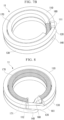
- a primary coil 100 as shown in FIG. 1A is generally utilized for heating the shaft-like body 51.
- the primary coil 100 is a coil having a solenoidal shape and is formed of a strand of a coil wound in a spiral shape.
- the primary coil 100 is caused to traverse in the axis C direction so that the shaft-like body 51 passes inside the primary coil 100 in a radial direction while causing a high-frequency electric current to flow through the primary coil 100, eddy currents sequentially occur on a surface of the shaft-like body 51 due to an electromagnetic induction phenomenon. As a result, the surface of the shaft-like body 51 is heated through heat generation according to a Joule's law.
- the reason why the coil is wound in the spiral shape having the form in which the coil is wound along the surface of the shaft-like body 51 is that, if a distance between the coil and the shaft-like body 51 increases, an influence of a change in magnetic flux density caused due to the coil on the shaft-like body 51 is reduced.
- Such an overheating phenomenon of the corner portion 54 can also occur in a corner portion 55 which is a place in which a diameter starts to change from the second main body part 52B toward the small diameter part 53.
- the inventors of the present invention have studied a method for minimizing an overheating phenomenon occurring in the corner portions 54 and 55 as described above using a secondary coil. As a result, in order to minimize the overheating phenomenon, it became clear that a very complicated mechanical mechanism in which a secondary coil can be freely disposed or removed in or from a gap between the primary coil 100 and the shaft-like body 51 (the small diameter part 53) needed to be introduced into a traverse hardening device.
- the inventors of the present invention have diligently studied a measure capable of hardening a shaft-like body having a form in which a diameter changes along an axis with a relatively simple constitution.
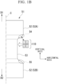
- a coil wound a plurality of times in the shape as shown in FIG. 1B as a primary coil 110, it is possible to minimize an overheating phenomenon occurring in the corner portions 54 and 55 without using a secondary coil or the like.
- a horizontal axis represents a radial direction of the primary coil 110 and a vertical axis represents a direction orthogonal to the radial direction in a plane orthogonal to a circumferential direction of the primary coil 110
- a cross-sectional image of the primary coil 110 which appears in the plane appears in a form of segmentations by a matrix of 2 pieces vertically ⁇ 2 pieces horizontally.
- the primary coil 110 having such a cross-sectional shape is utilized, as shown in FIG. 1B , when the primary coil 110 reaches a position corresponding to the upper end portion of the small diameter part 53, it is possible to keep the upper end portion of the primary coil 110 away from the corner portion 54. As a result, since it is possible to minimize the concentration of a magnetic flux on the corner portion 54, it is possible to minimize an overheating phenomenon occurring in the corner portion 54. Similarly, it is also possible to minimize an overheating phenomenon occurring in the corner portion 55.
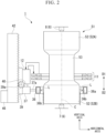
- FIG. 2 is a schematic side view showing a partial cutout portion of a traverse hardening device 1 according to the embodiment.
- the traverse hardening device 1 is a device for performing traverse hardening on the shaft-like body 51 such as an axle for a railroad vehicle using a high-frequency electric current.
- the shaft-like body 51 includes the main body part 52, and the small diameter part 53 provided on the intermediate section of the main body part 52 in the axis C direction.
- the main body part 52 and the small diameter part 53 are each formed in a columnar shape and the axis of the small diameter part 53 coincides with the axis C of the main body part 52.
- first main body part 52A a portion of the main body part 52 disposed on the one side D1 in the axis C direction with respect to the small diameter part 53 is referred to as the "first main body part 52A”.
- second main body part 52B a portion of the main body part 52 disposed on the other side D2 in the axis C direction with respect to the small diameter part 53 is referred to as the "second main body part 52B”.
- the first main body part 52A, the small diameter part 53, and the second main body part 52B are each formed in a columnar shape and are disposed on the common axis C.
- the outer diameter of the small diameter part 53 is smaller than the outer diameters of the first main body part 52A and the second main body part 52B.
- the shaft-like body 51 is formed of a conductive material such as carbon steel, low alloy steel containing not less than 95% by weight of iron (Fe), and the like which have ferrite.
- the traverse hardening device 1 includes a support member 6, a primary coil 11, a current transformer 12 (electric current supply device), a cooling ring 36, a pump 37 (cooling liquid supply device), uniaxial actuators (39, 40, 42), and a control device 46.
- the support member 6 includes a lower center 7 and an upper center 8.
- the lower center 7 supports the second main body part 52B of the shaft-like body 51 from below the second main body part 52B.
- the upper center 8 supports the first main body part 52A of the shaft-like body 51 from above the first main body part 52A.
- the lower center 7 and the upper center 8 support the shaft-like body 51 so that the axis C is directed in an upward/downward direction, the one side D1 in the axis C direction is directed upward, and the other side D2 is directed downward.
- the primary coil 11 is a coil which has an inner diameter larger than the outer diameter of the main body part 52 and has a solenoidal shape.
- a cross-sectional image of the primary coil 11 which appears in the plane appears in a form of segmentations by a matrix of 2 pieces vertically ⁇ 2 pieces horizontally when a horizontal axis represents a radial direction of the primary coil 11 in a plane orthogonal to the circumferential direction of the primary coil 11 and a vertical axis represents a direction orthogonal to the radial direction thereof. That is to say, on the right side of the paper surface of the axis C of FIG.
- a cross-sectional image of the primary coil 11 appears in a form of segmentations by a matrix of 2 pieces vertically ⁇ 2 pieces horizontally.
- a cross-sectional image of the primary coil 11 appears in a form of segmentations by a matrix of 2 pieces vertically ⁇ 2 pieces horizontally.
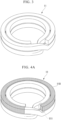
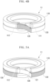
- FIG. 3 shows an example of the primary coil 11 having the cross-sectional shape as described above.
- FIG. 3 is a perspective view of the primary coil 11.
- the primary coil 11 shown in FIG. 3 can be manufactured through the following procedure.
- the primary coil 11 shown in FIG. 3 can be prepared through the procedure as described above.
- an outer diameter of the primary coil 11 means an outer diameter of the outer upper stage portion 110 and the outer lower stage portion 130 and an inner diameter of the primary coil 11 means an inner diameter of the inner lower stage portion 150 and the inner upper stage portion 170.
- the respective end portions (the first extraction end portion 111 and the second extraction end portion 171) of the primary coil 11 are electrically and mechanically connected to the current transformer 12.
- the current transformer 12 is an electric current supply device which supplies a high-frequency electric current to the primary coil 11 under the control of the control device 46. That is to say, a high-frequency electric current flows between the first extraction end portion 111 and the second extraction end portion 171 of the primary coil 11.
- the cooling ring 36 is a solenoidal shape member having an inner diameter larger than the outer diameter of the main body part 52.
- An internal space 36a is formed in the cooling ring 36.
- a plurality of nozzles 36b communicating with the internal space 36a are formed in an inner circumferential surface of the cooling ring 36 so as to be away from each other in the circumferential direction.
- the shaft-like body 51 is coaxially inserted inside the cooling ring 36 in the radial direction.
- the cooling ring 36 is disposed closer to the other side D2 in the axis C direction than the primary coil 11.
- the pump 37 is joined to the cooling ring 36 via a water supply pipe 37a.
- the pump 37 is a cooling liquid supply device which supplies a cooling liquid L such as water into the internal space 36a of the cooling ring 36 via the water supply pipe 37a under the control of the control device 46.
- the cooling liquid L supplied into the internal space 36a of the cooling ring 36 is ejected toward an outer circumferential surface of the shaft-like body 51 through the plurality of nozzles 36b to cool the shaft-like body 51.
- the primary coil 11, the current transformer 12, the cooling ring 36, and the pump 37 are fixed to a support plate 39.
- Pinions 39a are formed on the support plate 39.
- a motor 40 configured to drive the pinions 39a is attached to the support plate 39.
- the pinions 39a of the support plate 39 meshes with a rack 42. If the motor 40 is driven, the pinions 39a rotates forward or backward. Thus, the support plate 39 traverses upward or downward (that is, in the axis C direction) with respect to the rack 42.
- the rack 42 may be a ball screw.
- the plurality of pinions 39a may be disposed to have the ball screw disposed therebetween.
- the support plate 39 having the pinions 39a described above, the motor 40, and the rack 42 are mechanical elements constituting an example of the uniaxial actuators of the present invention. That is to say, each of the uniaxial actuators composed of these mechanical elements is configured to enable positioning of the primary coil 11 in the axis C direction which supporting the primary coil 11 and the cooling ring 36 so that the shaft-like body 51 passes inside the primary coil 11 and the cooling ring 36 in the radial direction and the primary coil 11 is disposed on the one side D1 in the axis C direction with respect to the cooling ring 36.
- the control device 46 includes an arithmetic circuit (not shown) and a memory (not shown).
- the memory has a control program or the like for driving the arithmetic circuit stored therein.
- the control device 46 is connected to the current transformer 12, the pump 37, and the motor 40 (the mechanical element of the uniaxial actuator) and synchronously controls these operations in accordance with the control program.
- the traverse hardening method according to the embodiment has, as a basic process, a preparatory process (first step) and a hardening process (second step).
- the shaft-like body 51 which is a body to be heated and the traverse hardening device 1 including the above constitution are prepared.
- the upper center 8 supports an end surface of the first main body part 52A on an upper side (the one side D1 in the axis C direction) so that the axis C of the shaft-like body 51 is perpendicular to a horizontal plane and the lower center 7 supports an end surface of the second main body part 52B on a lower side (the other side D2 in the axis C direction) (refer to FIG. 2 ).
- the one side D1 (upper side) in the axis C direction is a direction in which the primary coil 11 and the cooling ring 36 moves forward.
- the control device 46 of the traverse hardening device 1 performs, as an initial setting process, a process for traversing the primary coil 11 to an initial position (traverse start position) set in advance in the axis C direction and making the primary coil 11 stand by.
- the control device 46 controls the motor 40 of the uniaxial actuator so that the primary coil 11 stands by at a traverse start position set at a position corresponding to a lower end portion of the second main body part 52B.
- the traverse start position of the primary coil 11 may be set to a position corresponding to the lower end portion of the second main body part 52B.
- the traverse start position of the primary coil 11 may be set to a position which is away by a distance shorter than a coil width of the primary coil 11 in a direction orthogonal to the radial direction from the lower end portion of the second main body part 52B further to the other side D2 (lower side) in the axis C direction.
- the traverse start position may be set to a position in which the entire shaft-like body 51 can be subjected to induction heating through traversing (upward movement) of the primary coil 11.
- the uniaxial actuator including the support plate 39, the motor 40, and the rack 42 is configured to enable positioning of the primary coil 11 in the axis C direction while supporting the primary coil 11 and the cooling ring 36 so that the shaft-like body 51 passes coaxially inside the primary coil 11 and the cooling ring 36 in the radial direction and the primary coil 11 is disposed on the one side D1 (upper side) in the axis C direction with respect to the cooling ring 36.
- the uniaxial actuator composed of these mechanical elements it is possible to traverse the primary coil 11 to the traverse start position and make the primary coil 11 stand by in a state in which the primary coil 11 is disposed on the upper side (forward movement direction side) with respect to the cooling ring 36.
- the control device 46 controls the motor 40 of the uniaxial actuator so that the primary coil 11 traverses (moves upward) from the traverse start position toward the one side D1 (forward movement direction side) in the axis C direction.
- the cooling ring 36 also moves upward together with the primary coil 11 while a state in which the primary coil 11 is disposed on the upper side (forward movement direction side) with respect to the cooling ring 36 is being maintained.
- the control device 46 synchronously controls the current transformer 12, the pump 37, and the motor 40 of the uniaxial actuator so that a high-frequency electric current is supplied to the primary coil 11 and the cooling liquid L is supplied to the cooling ring 36 while the primary coil 11 and the cooling ring 36 are traversing in a forward movement direction.
- the current transformer 12, the pump 37, and the motor 40 of the uniaxial actuator are synchronously controlled.
- the second main body part 52B When the primary coil 11 moves upward in the axis C direction while receiving the supply of a high-frequency electric current, the second main body part 52B is subjected to continuous induction heating in the axis C direction and a metal structure of a surface of the second main body part 52B transforms into austenite.
- the cooling ring 36 since the cooling ring 36 also moves upward in the form in which the cooling ring 36 follows the primary coil 11, immediately after the second main body part 52B is subjected to induction heating, the second main body part 52B is continuously cooled in the axis C direction through the injection of the cooling liquid L from the cooling ring 36.
- the metal structure of the surface of the second main body part 52B transforms from the austenite into hard martensite. In this way, as the primary coil 11 and the cooling ring 36 move upward, the second main body part 52B is seamlessly hardened.
- the primary coil 11 After the primary coil 11 has passed through the second main body part 52B, the primary coil 11 then continues to move upward toward the forward movement direction side so that the small diameter part 53 of the shaft-like body 51 passes inside the primary coil 11 in the radial direction.
- the small diameter part 53 is subjected to continuous induction heating in the axis C direction and the metal structure of the surface of the small diameter part 53 transforms into austenite.
- the control device 46 controls the current transformer 12 so that an amplitude value of a high-frequency electric current flowing through the primary coil 11 increases.
- the cooling ring 36 While the primary coil 11 is passing through the small diameter part 53, the cooling ring 36 also moves upward in the form in which the cooling ring 36 follows the primary coil 11. For this reason, immediately after the small diameter part 53 is subjected to induction heating, the small diameter part 53 is continuously cooled in the axis C direction through the injection of the cooling liquid L from the cooling ring 36. As a result, the metal structure of the surface of the small diameter part 53 transforms from the austenite into hard martensite. In this way, as the primary coil 11 and the cooling ring 36 move upward, the small diameter part 53 is seamlessly hardened following the second main body part 52B.
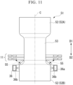
- FIG. 11 shows a state in which the primary coil 11 has reached a position corresponding to the lower end portion of the small diameter part 53.
- Reference numeral 55 indicates a corner portion which is a place in which a diameter starts to change from the second main body part 52B toward the small diameter part 53.
- FIG. 11 when the primary coil 11 has reached the position corresponding to the lower end portion of the small diameter part 53, it is possible to keep the lower end portion of the primary coil 11 away from the corner portion 55 of the shaft-like body 51.
- it is possible to minimize the concentration of a magnetic flux on the corner portion 55 it is also possible to minimize an overheating phenomenon occurring at the corner portion 55.
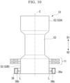
- FIG. 12 shows a state in which the primary coil 11 has reached a position corresponding to the upper end portion of the small diameter part 53.
- Reference numeral 54 indicates a corner portion which is a place in which a diameter starts to change from the first main body part 52A toward the small diameter part 53.
- FIG. 12 when the primary coil 11 has reached the position corresponding to the upper end portion of the small diameter part 53, it is possible to keep the upper end portion of the primary coil 11 away from the corner portion 54 of the shaft-like body 51.
- it is possible to minimize the concentration of a magnetic flux on the corner portion 54 it is also possible to minimize an overheating phenomenon occurring at the corner portion 54.
- the primary coil 11 After the primary coil 11 has passed through the small diameter part 53, the primary coil 11 then continues to move upward toward the forward movement direction so that the first main body part 52A of the shaft-like body 51 passes inside the primary coil 11 in the radial direction.
- the first main body part 52A is subjected to continuous induction heating in the axis C direction and the metal structure of the surface of the first main body part 52A transforms into austenite.
- the control device 46 controls the current transformer 12 so that an amplitude value of a high-frequency electric current flowing through the primary coil 11 returns to the original value.
- the cooling ring 36 While the primary coil 11 is passing through the first main body part 52A, the cooling ring 36 also moves upward following the primary coil 11. For this reason, immediately after the first main body part 52A has been subjected to induction heating, the first main body part 52A is continuously cooled in the axis C direction through the injection of the cooling liquid L from the cooling ring 36. As a result, the metal structure of the surface of the first main body part 52A transforms from the austenite into hard martensite. In this way, as the primary coil 11 and the cooling ring 36 move upward, the first main body part 52A is seamlessly hardened following the small diameter part 53.
- the control device 46 controls the motor 40 of the uniaxial actuator so that the primary coil 11 moves upward to a traverse stop position set to a position away from the first main body part 52A to the one side D1 in the axis C direction and the primary coil 11 stops at the traverse stop position.
- the control device 46 stops the supply of a high-frequency electric current when the primary coil 11 exceeds an upper end of the first main body part 52A.
- the current transformer 12 and the pump 37 are synchronously controlled together with the uniaxial actuator so that the cooling liquid L is continuously supplied to the cooling ring 36 until the primary coil 11 stops at the traverse stop position.
- the traverse hardening device 1 capable of hardening the shaft-like body 51 having a shape in which an outer diameter changes along the axis with a relatively simple constitution and the traverse hardening method which can be realized using the traverse hardening device 1.
- the shaft-like body 51 may not be disposed so that the axis C is disposed in the upward/downward direction (vertical direction) and the axis C may be disposed to be inclined with respect to the upward/downward direction.
- the primary coil 11 and the cooling ring 36 traverse to be inclined in the upward/downward direction.
- the shaft-like body 51 is assumed to be an axle for a railroad vehicle, the shaft-like body 51 may be another shaft-like body such as a ball screw.
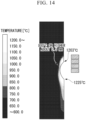
- FIG. 14 shows the results of simulation analysis of a surface temperature distribution of the shaft-like body 51 when the shaft-like body 51 is subjected to induction heating using the primary coil 100 (refer to FIG. 1A ) having a general cross-sectional shape.
- FIG. 14 shows only the analysis result of the right half of a vertical cross-sectional view of the shaft-like body 51 with respect to the axis C.
- the outer diameter of the main body part 52 (the first main body part 52A, the second main body part 52B) was set to 198 mm and the outer diameter (minimum diameter) of the small diameter part 53 was set to 181 mm. Furthermore, a material of the shaft-like body 51 was set to carbon steel. A frequency of a high-frequency electric current flowing through the primary coil 100 was set to 1 kHz. A frequency at the time of heating the small diameter part 53 and a frequency at the time of heating the main body part 52 are the same.
- FIG. 14 shows the analysis result of a maximum value of a surface temperature distribution of the shaft-like body 51 when the shaft-like body 51 is subjected to heating required for performing hardening up to a certain depth through traverse hardening.
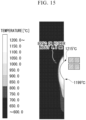
- FIG. 15 shows the results of simulation analysis of a surface temperature distribution of the shaft-like body 51 when the shaft-like body 51 is subjected to induction heating using the primary coil 11 of the embodiment (that is, using the traverse hardening device 1 in the embodiment described above).
- FIG. 15 shows only the analysis result of the right half of the vertical cross-sectional view of the shaft-like body 51 with respect to the axis C.
- the outer diameter of the main body part 52 (the first main body part 52A, the second main body part 52B) was set to 198 mm and the outer diameter (minimum diameter) of the small diameter part 53 was set to 181 mm. Furthermore, a material of the shaft-like body 51 was set to carbon steel. A frequency of a high-frequency electric current flowing through the primary coil 11 was set to 1 kHz.
- FIG. 15 shows the analysis result of the surface temperature distribution of the shaft-like body 51 when the shaft-like body 51 is subjected to heating required for performing hardening up to a certain depth through traverse hardening.
- the small diameter part 53 is heated to 800°C or higher from the surface to a region having a depth of about 3.5 mm and a maximum value of the surface temperature distribution is 1225°C.
- the small diameter part 53 is heated to 800°C or higher from the surface to a region having a depth of about 4.8 mm and a maximum value of the surface temperature distribution is 1215°C.
- the entire shaft state 51 can be heated at a high temperature of 800°C or higher in a deeper region from the surface and the shaft-like body 51 can be sufficiently heated and hardened as much as needed with a relatively simple constitution. Furthermore, as compared with the comparative example, according to the example of the present invention, it was confirmed that it is possible to minimize an overheating phenomenon by reducing a maximum value of a surface temperature of the shaft-like body 51.
- the cross-sectional image of the primary coil which appears on the plane may appear in a form of segmentations by a matrix of 3 pieces vertically ⁇ 2 pieces horizontally.
- the cross-sectional image of the primary coil which appears on the plane may appear in a form of segmentations by a matrix of 2 pieces vertically ⁇ 3 piece horizontally.
- the cross-sectional image of the primary coil which appears on the plane may appear in a form of segmentations by a matrix of 3 pieces vertically ⁇ 3 pieces horizontally.
- a traverse hardening device capable of hardening a shaft-like body having a shape in which a diameter changes along an axis with a relatively simple constitution, and a traverse hardening method which can be realized using the traverse hardening device. Therefore, industrial applicability is high.
Landscapes
- Chemical & Material Sciences (AREA)
- Engineering & Computer Science (AREA)
- Physics & Mathematics (AREA)
- Thermal Sciences (AREA)
- Crystallography & Structural Chemistry (AREA)
- Mechanical Engineering (AREA)
- Materials Engineering (AREA)
- Metallurgy (AREA)
- Organic Chemistry (AREA)
- Electromagnetism (AREA)
- Heat Treatment Of Articles (AREA)
- General Induction Heating (AREA)
Claims (6)
- Traversalhärtungsvorrichtung, die eine Traversalhärtung an einem schaftartigen Körper durchführt, der einen Hauptkörperteil und einen Teil mit kleinem Durchmesser aufweist, der in einem Zwischenabschnitt des Hauptkörperteils in einer axialen Richtung vorgesehen ist und einen Außendurchmesser aufweist, der kleiner ist als der des Hauptkörperteils, umfassend:eine Primärspule mit einem Innendurchmesser, der größer ist als ein Außendurchmesser des Hauptkörperteils, und mit einer Solenoidform;eine elektrische Stromversorgungsvorrichtung, die einen hochfrequenten elektrischen Strom an die Primärspule zuführt;einen einachsigen Aktuator, der so konfiguriert ist, dass er die Positionierung der Primärspule in der axialen Richtung ermöglicht, während er die Primärspule so stützt, dass der schaftartige Körper in einer radialen Richtung in die Primärspule hineinläuft; undeine Steuervorrichtung, die die elektrische Stromversorgungsvorrichtung und den einachsigen Aktuator steuert,wobei, wenn eine horizontale Achse eine radiale Richtung der Primärspule und eine vertikale Achse eine Richtung orthogonal zu der radialen Richtung in einer Ebene orthogonal zu einer Umfangsrichtung der Primärspule darstellt, ein Querschnittsbild der Primärspule, das auf der Ebene erscheint, in einer Form von Segmentierungen durch eine Matrix von m Stücken vertikal × n Stücken horizontal erscheint, wobei m und n jeweils eine ganze Zahl von 2 oder mehr als 2 sind.
- Traversalhärtungsvorrichtung nach Anspruch 1, wobei das Querschnittsbild der Primärspule, das auf der Ebene erscheint, in Form von Segmentierungen durch eine Matrix von 2 Stücken vertikal × 2 Stücken horizontal erscheint.
- Traversalhärtungsvorrichtung nach Anspruch 1 oder 2, ferner umfassend:einen Kühlring mit einem Innendurchmesser, der größer ist als ein Außendurchmesser des Hauptkörperteils, und mit einer Innenumfangsfläche, in der eine Vielzahl von Düsen vorgesehen ist; und
eine Kühlflüssigkeitszuführvorrichtung, die eine Kühlflüssigkeit dem Kühlring zuführt,wobei der uniaxiale Aktuator so konfiguriert ist, dass er die Positionierung der Primärspule in der axialen Richtung ermöglicht, während er die Primärspule und den Kühlring so stützt, dass der schaftartige Körper in eine radiale Richtung in die Primärspule und den Kühlring hineinläuft und die Primärspule in der axialen Richtung in Bezug auf den Kühlring auf einer Seite angeordnet ist, unddie Steuervorrichtung den einachsigen Aktuator, die elektrische Stromversorgungsvorrichtung und die Kühlflüssigkeitszuführvorrichtung synchron steuert, so dass die Primärspule und der Kühlring von der anderen Seite in der axialen Richtung zu der einen Seite hin durchlaufen, während der elektrische Hochfrequenzstrom an die Primärspule zugeführt wird und die Kühlflüssigkeit dem Kühlring zugeführt wird. - Traversalhärtungsverfahren, das eine Traversalhärtung an einem schaftartigen Körper durchführt, der einen Hauptkörperteil und einen Teil mit kleinem Durchmesser aufweist, der in einem Zwischenabschnitt des Hauptkörperteils in einer axialen Richtung vorgesehen ist und einen Außendurchmesser aufweist, der kleiner als der des Hauptkörperteils ist, umfassend:einen ersten Schritt des Vorbereitens einer Primärspule mit einem Innendurchmesser, der größer als ein Außendurchmesser des Hauptkörperteils ist, und mit einer Solenoidform; undeinen zweiten Schritt des Durchquerens der Primärspule in der axialen Richtung, so dass der schaftartige Körper in einer radialen Richtung durch die Primärspule hineinläuft, während ein hochfrequenter elektrischer Strom an die Primärspule zugeführt wird,wobei, wenn eine horizontale Achse eine radiale Richtung der Primärspule und eine vertikale Achse eine Richtung orthogonal zu der radialen Richtung in einer Ebene orthogonal zu einer Umfangsrichtung der Primärspule darstellt, ein Querschnittsbild der Primärspule, das auf der Ebene erscheint, in einer Form von Segmentierungen durch eine Matrix von m Stücken vertikal × n Stücken horizontal erscheint, wobei m und n jeweils eine ganze Zahl von 2 oder mehr als 2 sind.
- Traversalhärtungsverfahren gemäß Anspruch 4, wobei das Querschnittsbild der Primärspule, das auf der Ebene erscheint, in Form von Segmentierungen durch eine Matrix von 2 Stücken vertikal × 2 Stücken horizontal erscheint.
- Traversalhärtungsverfahren nach Anspruch 4 oder 5, wobei der erste Schritt das Vorbereiten eines Kühlrings mit einem Innendurchmesser, der größer als ein Außendurchmesser des Hauptkörperteils ist, und mit einer Innenumfangsfläche, in der eine Vielzahl von Düsen vorgesehen ist, zusätzlich zu der Primärspule umfasst, und
der zweite Schritt das Durchqueren der Primärspule und des Kühlrings von der anderen Seite in der axialen Richtung zu der einen Seite umfasst, so dass der schaftartige Körper in der radialen Richtung in die Primärspule und den Kühlring hineinläuft, während der elektrische Hochfrequenzstrom der Primärspule zugeführt wird und dem Kühlring eine Kühlflüssigkeit zugeführt wird, in einem Zustand, in dem die Primärspule auf der einen Seite in der axialer Richtung in Bezug auf den Kühlring angeordnet ist.
Applications Claiming Priority (2)
| Application Number | Priority Date | Filing Date | Title |
|---|---|---|---|
| JP2019096624 | 2019-05-23 | ||
| PCT/JP2020/019979 WO2020235602A1 (ja) | 2019-05-23 | 2020-05-20 | 移動焼入れ装置及び移動焼入れ方法 |
Publications (3)
| Publication Number | Publication Date |
|---|---|
| EP3974548A1 EP3974548A1 (de) | 2022-03-30 |
| EP3974548A4 EP3974548A4 (de) | 2022-06-01 |
| EP3974548B1 true EP3974548B1 (de) | 2025-05-14 |
Family
ID=73458506
Family Applications (1)
| Application Number | Title | Priority Date | Filing Date |
|---|---|---|---|
| EP20810744.1A Active EP3974548B1 (de) | 2019-05-23 | 2020-05-20 | Vorrichtung zum härten einer traverse und verfahren zum härten einer traverse |
Country Status (5)
| Country | Link |
|---|---|
| EP (1) | EP3974548B1 (de) |
| JP (1) | JP7151888B2 (de) |
| CN (1) | CN113874530B (de) |
| TW (1) | TWI743797B (de) |
| WO (1) | WO2020235602A1 (de) |
Families Citing this family (3)
| Publication number | Priority date | Publication date | Assignee | Title |
|---|---|---|---|---|
| WO2021006062A1 (ja) * | 2019-07-09 | 2021-01-14 | 日本製鉄株式会社 | 移動焼入れ装置及び移動焼入れ方法 |
| US20250318020A1 (en) * | 2022-06-28 | 2025-10-09 | Nippon Steel Corporation | Traverse hardening device and traverse hardening method |
| WO2024004142A1 (ja) * | 2022-06-30 | 2024-01-04 | 日本製鉄株式会社 | 移動焼入れ装置 |
Family Cites Families (12)
| Publication number | Priority date | Publication date | Assignee | Title |
|---|---|---|---|---|
| JPS5221215B2 (de) | 1971-09-17 | 1977-06-09 | ||
| JP2000087134A (ja) | 1998-09-08 | 2000-03-28 | High Frequency Heattreat Co Ltd | 段付き軸体の誘導加熱コイルおよび焼入装置 |
| JP3300290B2 (ja) * | 1998-09-22 | 2002-07-08 | 富士電子工業株式会社 | 高周波焼入コイル体 |
| CN1282753C (zh) * | 2003-09-26 | 2006-11-01 | 上海纳铁福传动轴有限公司 | 阶梯轴感应加热淬火装置及方法 |
| JP2007162104A (ja) * | 2005-12-16 | 2007-06-28 | Denki Kogyo Co Ltd | 高周波誘導加熱コイル |
| CN202116607U (zh) * | 2011-05-18 | 2012-01-18 | 柳州中驰成达机械锻造有限公司 | 阶梯轴类淬火感应圈 |
| CN102181615B (zh) * | 2011-05-18 | 2013-06-12 | 柳州中驰成达机械锻造有限公司 | 汽车半轴淬火工艺方法及淬火感应圈 |
| JP6101608B2 (ja) * | 2013-09-17 | 2017-03-22 | 高周波熱錬株式会社 | 誘導加熱コイル及び誘導加熱装置並びに加熱方法 |
| JP6240975B2 (ja) * | 2013-10-25 | 2017-12-06 | 高周波熱錬株式会社 | 誘導加熱装置及び方法並びに熱処理装置及び方法 |
| JP6427391B2 (ja) * | 2014-11-11 | 2018-11-21 | 高周波熱錬株式会社 | 焼入れ装置及び焼入れ方法 |
| CN108866279B (zh) * | 2018-08-20 | 2024-03-08 | 邢台隆科机械有限公司 | 一种高频淬火装置 |
| JP2019096624A (ja) | 2019-03-08 | 2019-06-20 | 国立大学法人九州大学 | 電極材料 |
-
2020
- 2020-05-20 TW TW109116754A patent/TWI743797B/zh active
- 2020-05-20 EP EP20810744.1A patent/EP3974548B1/de active Active
- 2020-05-20 WO PCT/JP2020/019979 patent/WO2020235602A1/ja not_active Ceased
- 2020-05-20 CN CN202080037355.1A patent/CN113874530B/zh active Active
- 2020-05-20 JP JP2021520822A patent/JP7151888B2/ja active Active
Also Published As
| Publication number | Publication date |
|---|---|
| CN113874530B (zh) | 2023-07-04 |
| WO2020235602A1 (ja) | 2020-11-26 |
| JP7151888B2 (ja) | 2022-10-12 |
| EP3974548A4 (de) | 2022-06-01 |
| EP3974548A1 (de) | 2022-03-30 |
| JPWO2020235602A1 (de) | 2020-11-26 |
| TWI743797B (zh) | 2021-10-21 |
| TW202100758A (zh) | 2021-01-01 |
| CN113874530A (zh) | 2021-12-31 |
Similar Documents
| Publication | Publication Date | Title |
|---|---|---|
| EP3974548B1 (de) | Vorrichtung zum härten einer traverse und verfahren zum härten einer traverse | |
| RU2605020C2 (ru) | Нагревательное устройство и содержащий его аппарат для нагревания непрерывного металлического листа | |
| JP4940132B2 (ja) | 誘導加熱による加工品の多周波熱処理 | |
| US10034331B2 (en) | Controlled electric induction heating of an electrically conductive workpiece in a solenoidal coil with flux compensators | |
| JP6101608B2 (ja) | 誘導加熱コイル及び誘導加熱装置並びに加熱方法 | |
| JP6958725B2 (ja) | 移動焼入れ装置及び移動焼入れ方法 | |
| JP2008204648A (ja) | 誘導加熱装置 | |
| EP3998360A1 (de) | Mobile abschreckvorrichtung und mobiles abschreckverfahren | |
| WO2014088423A1 (en) | Apparatus and method for induction heating of magnetic materials | |
| US11425799B2 (en) | Heating coil | |
| JP7311811B2 (ja) | 移動焼入れ装置及び移動焼入れ方法 | |
| EP3975664B1 (de) | Sekundärspulenmodul, vorschubhärtungsvorrichtung und vorschubhärtungsverfahren | |
| EP4549597A1 (de) | Vorrichtung zum härten einer traverse und verfahren zum härten einer traverse | |
| JP2010182594A (ja) | 金属板の誘導加熱装置 | |
| JP6343443B2 (ja) | 誘導加熱コイル及び誘導加熱方法 | |
| US20250327144A1 (en) | Traverse hardening device | |
| JP2005122986A (ja) | 誘導加熱装置 |
Legal Events
| Date | Code | Title | Description |
|---|---|---|---|
| STAA | Information on the status of an ep patent application or granted ep patent |
Free format text: STATUS: THE INTERNATIONAL PUBLICATION HAS BEEN MADE |
|
| PUAI | Public reference made under article 153(3) epc to a published international application that has entered the european phase |
Free format text: ORIGINAL CODE: 0009012 |
|
| STAA | Information on the status of an ep patent application or granted ep patent |
Free format text: STATUS: REQUEST FOR EXAMINATION WAS MADE |
|
| 17P | Request for examination filed |
Effective date: 20211108 |
|
| AK | Designated contracting states |
Kind code of ref document: A1 Designated state(s): AL AT BE BG CH CY CZ DE DK EE ES FI FR GB GR HR HU IE IS IT LI LT LU LV MC MK MT NL NO PL PT RO RS SE SI SK SM TR |
|
| A4 | Supplementary search report drawn up and despatched |
Effective date: 20220503 |
|
| RIC1 | Information provided on ipc code assigned before grant |
Ipc: C21D 1/667 20060101ALI20220426BHEP Ipc: C21D 1/18 20060101ALI20220426BHEP Ipc: C21D 9/00 20060101ALI20220426BHEP Ipc: H05B 6/10 20060101ALI20220426BHEP Ipc: C21D 1/42 20060101ALI20220426BHEP Ipc: C21D 1/10 20060101ALI20220426BHEP Ipc: C21D 9/28 20060101AFI20220426BHEP |
|
| DAV | Request for validation of the european patent (deleted) | ||
| DAX | Request for extension of the european patent (deleted) | ||
| REG | Reference to a national code |
Ref country code: DE Free format text: PREVIOUS MAIN CLASS: C21D0009280000 Ipc: C21D0001100000 Ref country code: DE Ref legal event code: R079 Ref document number: 602020051338 Country of ref document: DE Free format text: PREVIOUS MAIN CLASS: C21D0009280000 Ipc: C21D0001100000 |
|
| GRAP | Despatch of communication of intention to grant a patent |
Free format text: ORIGINAL CODE: EPIDOSNIGR1 |
|
| STAA | Information on the status of an ep patent application or granted ep patent |
Free format text: STATUS: GRANT OF PATENT IS INTENDED |
|
| RIC1 | Information provided on ipc code assigned before grant |
Ipc: H05B 6/40 20060101ALI20241126BHEP Ipc: H05B 6/36 20060101ALI20241126BHEP Ipc: H05B 6/10 20060101ALI20241126BHEP Ipc: C21D 1/667 20060101ALI20241126BHEP Ipc: C21D 1/18 20060101ALI20241126BHEP Ipc: C21D 9/00 20060101ALI20241126BHEP Ipc: C21D 9/28 20060101ALI20241126BHEP Ipc: C21D 1/42 20060101ALI20241126BHEP Ipc: C21D 1/10 20060101AFI20241126BHEP |
|
| INTG | Intention to grant announced |
Effective date: 20241206 |
|
| RIN1 | Information on inventor provided before grant (corrected) |
Inventor name: KOZUKA, CHIHIRO Inventor name: HATA, TOSHIYUKI Inventor name: YAMANE, AKIHITO |
|
| GRAS | Grant fee paid |
Free format text: ORIGINAL CODE: EPIDOSNIGR3 |
|
| GRAA | (expected) grant |
Free format text: ORIGINAL CODE: 0009210 |
|
| STAA | Information on the status of an ep patent application or granted ep patent |
Free format text: STATUS: THE PATENT HAS BEEN GRANTED |
|
| AK | Designated contracting states |
Kind code of ref document: B1 Designated state(s): AL AT BE BG CH CY CZ DE DK EE ES FI FR GB GR HR HU IE IS IT LI LT LU LV MC MK MT NL NO PL PT RO RS SE SI SK SM TR |
|
| REG | Reference to a national code |
Ref country code: GB Ref legal event code: FG4D |
|
| REG | Reference to a national code |
Ref country code: CH Ref legal event code: EP |
|
| REG | Reference to a national code |
Ref country code: IE Ref legal event code: FG4D |
|
| REG | Reference to a national code |
Ref country code: DE Ref legal event code: R096 Ref document number: 602020051338 Country of ref document: DE |
|
| PGFP | Annual fee paid to national office [announced via postgrant information from national office to epo] |
Ref country code: DE Payment date: 20250520 Year of fee payment: 6 |
|
| REG | Reference to a national code |
Ref country code: NL Ref legal event code: MP Effective date: 20250514 |
|
| PG25 | Lapsed in a contracting state [announced via postgrant information from national office to epo] |
Ref country code: PT Free format text: LAPSE BECAUSE OF FAILURE TO SUBMIT A TRANSLATION OF THE DESCRIPTION OR TO PAY THE FEE WITHIN THE PRESCRIBED TIME-LIMIT Effective date: 20250915 Ref country code: ES Free format text: LAPSE BECAUSE OF FAILURE TO SUBMIT A TRANSLATION OF THE DESCRIPTION OR TO PAY THE FEE WITHIN THE PRESCRIBED TIME-LIMIT Effective date: 20250514 Ref country code: FI Free format text: LAPSE BECAUSE OF FAILURE TO SUBMIT A TRANSLATION OF THE DESCRIPTION OR TO PAY THE FEE WITHIN THE PRESCRIBED TIME-LIMIT Effective date: 20250514 |
|
| REG | Reference to a national code |
Ref country code: LT Ref legal event code: MG9D |
|
| PG25 | Lapsed in a contracting state [announced via postgrant information from national office to epo] |
Ref country code: GR Free format text: LAPSE BECAUSE OF FAILURE TO SUBMIT A TRANSLATION OF THE DESCRIPTION OR TO PAY THE FEE WITHIN THE PRESCRIBED TIME-LIMIT Effective date: 20250815 Ref country code: NO Free format text: LAPSE BECAUSE OF FAILURE TO SUBMIT A TRANSLATION OF THE DESCRIPTION OR TO PAY THE FEE WITHIN THE PRESCRIBED TIME-LIMIT Effective date: 20250814 |
|
| PG25 | Lapsed in a contracting state [announced via postgrant information from national office to epo] |
Ref country code: NL Free format text: LAPSE BECAUSE OF FAILURE TO SUBMIT A TRANSLATION OF THE DESCRIPTION OR TO PAY THE FEE WITHIN THE PRESCRIBED TIME-LIMIT Effective date: 20250514 Ref country code: PL Free format text: LAPSE BECAUSE OF FAILURE TO SUBMIT A TRANSLATION OF THE DESCRIPTION OR TO PAY THE FEE WITHIN THE PRESCRIBED TIME-LIMIT Effective date: 20250514 |
|
| PGFP | Annual fee paid to national office [announced via postgrant information from national office to epo] |
Ref country code: IT Payment date: 20250829 Year of fee payment: 6 |
|
| REG | Reference to a national code |
Ref country code: AT Ref legal event code: MK05 Ref document number: 1794836 Country of ref document: AT Kind code of ref document: T Effective date: 20250514 |
|
| PG25 | Lapsed in a contracting state [announced via postgrant information from national office to epo] |
Ref country code: BG Free format text: LAPSE BECAUSE OF FAILURE TO SUBMIT A TRANSLATION OF THE DESCRIPTION OR TO PAY THE FEE WITHIN THE PRESCRIBED TIME-LIMIT Effective date: 20250514 |
|
| PG25 | Lapsed in a contracting state [announced via postgrant information from national office to epo] |
Ref country code: HR Free format text: LAPSE BECAUSE OF FAILURE TO SUBMIT A TRANSLATION OF THE DESCRIPTION OR TO PAY THE FEE WITHIN THE PRESCRIBED TIME-LIMIT Effective date: 20250514 |
|
| PG25 | Lapsed in a contracting state [announced via postgrant information from national office to epo] |
Ref country code: AT Free format text: LAPSE BECAUSE OF FAILURE TO SUBMIT A TRANSLATION OF THE DESCRIPTION OR TO PAY THE FEE WITHIN THE PRESCRIBED TIME-LIMIT Effective date: 20250514 |
|
| PGFP | Annual fee paid to national office [announced via postgrant information from national office to epo] |
Ref country code: FR Payment date: 20250708 Year of fee payment: 6 |
|
| PG25 | Lapsed in a contracting state [announced via postgrant information from national office to epo] |
Ref country code: RS Free format text: LAPSE BECAUSE OF FAILURE TO SUBMIT A TRANSLATION OF THE DESCRIPTION OR TO PAY THE FEE WITHIN THE PRESCRIBED TIME-LIMIT Effective date: 20250814 |
|
| PGFP | Annual fee paid to national office [announced via postgrant information from national office to epo] |
Ref country code: CZ Payment date: 20250703 Year of fee payment: 6 |
|
| PG25 | Lapsed in a contracting state [announced via postgrant information from national office to epo] |
Ref country code: IS Free format text: LAPSE BECAUSE OF FAILURE TO SUBMIT A TRANSLATION OF THE DESCRIPTION OR TO PAY THE FEE WITHIN THE PRESCRIBED TIME-LIMIT Effective date: 20250914 |
|
| PG25 | Lapsed in a contracting state [announced via postgrant information from national office to epo] |
Ref country code: LV Free format text: LAPSE BECAUSE OF FAILURE TO SUBMIT A TRANSLATION OF THE DESCRIPTION OR TO PAY THE FEE WITHIN THE PRESCRIBED TIME-LIMIT Effective date: 20250514 |
|
| REG | Reference to a national code |
Ref country code: CH Ref legal event code: H13 Free format text: ST27 STATUS EVENT CODE: U-0-0-H10-H13 (AS PROVIDED BY THE NATIONAL OFFICE) Effective date: 20251223 |
|
| PG25 | Lapsed in a contracting state [announced via postgrant information from national office to epo] |
Ref country code: DK Free format text: LAPSE BECAUSE OF FAILURE TO SUBMIT A TRANSLATION OF THE DESCRIPTION OR TO PAY THE FEE WITHIN THE PRESCRIBED TIME-LIMIT Effective date: 20250514 Ref country code: SM Free format text: LAPSE BECAUSE OF FAILURE TO SUBMIT A TRANSLATION OF THE DESCRIPTION OR TO PAY THE FEE WITHIN THE PRESCRIBED TIME-LIMIT Effective date: 20250514 |
|
| PG25 | Lapsed in a contracting state [announced via postgrant information from national office to epo] |
Ref country code: LU Free format text: LAPSE BECAUSE OF NON-PAYMENT OF DUE FEES Effective date: 20250520 |
|
| PG25 | Lapsed in a contracting state [announced via postgrant information from national office to epo] |
Ref country code: CH Free format text: LAPSE BECAUSE OF NON-PAYMENT OF DUE FEES Effective date: 20250531 |
|
| PG25 | Lapsed in a contracting state [announced via postgrant information from national office to epo] |
Ref country code: EE Free format text: LAPSE BECAUSE OF FAILURE TO SUBMIT A TRANSLATION OF THE DESCRIPTION OR TO PAY THE FEE WITHIN THE PRESCRIBED TIME-LIMIT Effective date: 20250514 |
|
| PG25 | Lapsed in a contracting state [announced via postgrant information from national office to epo] |
Ref country code: RO Free format text: LAPSE BECAUSE OF FAILURE TO SUBMIT A TRANSLATION OF THE DESCRIPTION OR TO PAY THE FEE WITHIN THE PRESCRIBED TIME-LIMIT Effective date: 20250514 Ref country code: SK Free format text: LAPSE BECAUSE OF FAILURE TO SUBMIT A TRANSLATION OF THE DESCRIPTION OR TO PAY THE FEE WITHIN THE PRESCRIBED TIME-LIMIT Effective date: 20250514 |
|
| REG | Reference to a national code |
Ref country code: BE Ref legal event code: MM Effective date: 20250531 |
|
| PG25 | Lapsed in a contracting state [announced via postgrant information from national office to epo] |
Ref country code: MC Free format text: LAPSE BECAUSE OF FAILURE TO SUBMIT A TRANSLATION OF THE DESCRIPTION OR TO PAY THE FEE WITHIN THE PRESCRIBED TIME-LIMIT Effective date: 20250514 |
|
| PLBE | No opposition filed within time limit |
Free format text: ORIGINAL CODE: 0009261 |
|
| STAA | Information on the status of an ep patent application or granted ep patent |
Free format text: STATUS: NO OPPOSITION FILED WITHIN TIME LIMIT |
|
| REG | Reference to a national code |
Ref country code: CH Ref legal event code: L10 Free format text: ST27 STATUS EVENT CODE: U-0-0-L10-L00 (AS PROVIDED BY THE NATIONAL OFFICE) Effective date: 20260325 |