EP3971403A2 - Steuerung eines dieselrussfiltersystems - Google Patents
Steuerung eines dieselrussfiltersystems Download PDFInfo
- Publication number
- EP3971403A2 EP3971403A2 EP21192221.6A EP21192221A EP3971403A2 EP 3971403 A2 EP3971403 A2 EP 3971403A2 EP 21192221 A EP21192221 A EP 21192221A EP 3971403 A2 EP3971403 A2 EP 3971403A2
- Authority
- EP
- European Patent Office
- Prior art keywords
- hydraulic
- engine
- controller
- dpf
- threshold
- Prior art date
- Legal status (The legal status is an assumption and is not a legal conclusion. Google has not performed a legal analysis and makes no representation as to the accuracy of the status listed.)
- Pending
Links
Images


Classifications
-
- F—MECHANICAL ENGINEERING; LIGHTING; HEATING; WEAPONS; BLASTING
- F02—COMBUSTION ENGINES; HOT-GAS OR COMBUSTION-PRODUCT ENGINE PLANTS
- F02D—CONTROLLING COMBUSTION ENGINES
- F02D41/00—Electrical control of supply of combustible mixture or its constituents
- F02D41/02—Circuit arrangements for generating control signals
- F02D41/021—Introducing corrections for particular conditions exterior to the engine
- F02D41/0235—Introducing corrections for particular conditions exterior to the engine in relation with the state of the exhaust gas treating apparatus
- F02D41/027—Introducing corrections for particular conditions exterior to the engine in relation with the state of the exhaust gas treating apparatus to purge or regenerate the exhaust gas treating apparatus
- F02D41/029—Introducing corrections for particular conditions exterior to the engine in relation with the state of the exhaust gas treating apparatus to purge or regenerate the exhaust gas treating apparatus the exhaust gas treating apparatus being a particulate filter
-
- F—MECHANICAL ENGINEERING; LIGHTING; HEATING; WEAPONS; BLASTING
- F02—COMBUSTION ENGINES; HOT-GAS OR COMBUSTION-PRODUCT ENGINE PLANTS
- F02D—CONTROLLING COMBUSTION ENGINES
- F02D41/00—Electrical control of supply of combustible mixture or its constituents
- F02D41/02—Circuit arrangements for generating control signals
- F02D41/0205—Circuit arrangements for generating control signals using an auxiliary engine speed control
-
- E—FIXED CONSTRUCTIONS
- E02—HYDRAULIC ENGINEERING; FOUNDATIONS; SOIL SHIFTING
- E02F—DREDGING; SOIL-SHIFTING
- E02F9/00—Component parts of dredgers or soil-shifting machines, not restricted to one of the kinds covered by groups E02F3/00 - E02F7/00
- E02F9/20—Drives; Control devices
- E02F9/2058—Electric or electro-mechanical or mechanical control devices of vehicle sub-units
- E02F9/2062—Control of propulsion units
- E02F9/2066—Control of propulsion units of the type combustion engines
-
- E—FIXED CONSTRUCTIONS
- E02—HYDRAULIC ENGINEERING; FOUNDATIONS; SOIL SHIFTING
- E02F—DREDGING; SOIL-SHIFTING
- E02F9/00—Component parts of dredgers or soil-shifting machines, not restricted to one of the kinds covered by groups E02F3/00 - E02F7/00
- E02F9/20—Drives; Control devices
- E02F9/22—Hydraulic or pneumatic drives
- E02F9/2246—Control of prime movers, e.g. depending on the hydraulic load of work tools
-
- E—FIXED CONSTRUCTIONS
- E02—HYDRAULIC ENGINEERING; FOUNDATIONS; SOIL SHIFTING
- E02F—DREDGING; SOIL-SHIFTING
- E02F9/00—Component parts of dredgers or soil-shifting machines, not restricted to one of the kinds covered by groups E02F3/00 - E02F7/00
- E02F9/20—Drives; Control devices
- E02F9/22—Hydraulic or pneumatic drives
- E02F9/2278—Hydraulic circuits
- E02F9/2282—Systems using center bypass type changeover valves
-
- F—MECHANICAL ENGINEERING; LIGHTING; HEATING; WEAPONS; BLASTING
- F01—MACHINES OR ENGINES IN GENERAL; ENGINE PLANTS IN GENERAL; STEAM ENGINES
- F01N—GAS-FLOW SILENCERS OR EXHAUST APPARATUS FOR MACHINES OR ENGINES IN GENERAL; GAS-FLOW SILENCERS OR EXHAUST APPARATUS FOR INTERNAL-COMBUSTION ENGINES
- F01N3/00—Exhaust or silencing apparatus having means for purifying, rendering innocuous, or otherwise treating exhaust
- F01N3/02—Exhaust or silencing apparatus having means for purifying, rendering innocuous, or otherwise treating exhaust for cooling, or for removing solid constituents of, exhaust
- F01N3/021—Exhaust or silencing apparatus having means for purifying, rendering innocuous, or otherwise treating exhaust for cooling, or for removing solid constituents of, exhaust by means of filters
- F01N3/023—Exhaust or silencing apparatus having means for purifying, rendering innocuous, or otherwise treating exhaust for cooling, or for removing solid constituents of, exhaust by means of filters using means for regenerating the filters, e.g. by burning trapped particles
-
- F—MECHANICAL ENGINEERING; LIGHTING; HEATING; WEAPONS; BLASTING
- F01—MACHINES OR ENGINES IN GENERAL; ENGINE PLANTS IN GENERAL; STEAM ENGINES
- F01N—GAS-FLOW SILENCERS OR EXHAUST APPARATUS FOR MACHINES OR ENGINES IN GENERAL; GAS-FLOW SILENCERS OR EXHAUST APPARATUS FOR INTERNAL-COMBUSTION ENGINES
- F01N3/00—Exhaust or silencing apparatus having means for purifying, rendering innocuous, or otherwise treating exhaust
- F01N3/02—Exhaust or silencing apparatus having means for purifying, rendering innocuous, or otherwise treating exhaust for cooling, or for removing solid constituents of, exhaust
- F01N3/021—Exhaust or silencing apparatus having means for purifying, rendering innocuous, or otherwise treating exhaust for cooling, or for removing solid constituents of, exhaust by means of filters
- F01N3/033—Exhaust or silencing apparatus having means for purifying, rendering innocuous, or otherwise treating exhaust for cooling, or for removing solid constituents of, exhaust by means of filters in combination with other devices
- F01N3/035—Exhaust or silencing apparatus having means for purifying, rendering innocuous, or otherwise treating exhaust for cooling, or for removing solid constituents of, exhaust by means of filters in combination with other devices with catalytic reactors
-
- F—MECHANICAL ENGINEERING; LIGHTING; HEATING; WEAPONS; BLASTING
- F01—MACHINES OR ENGINES IN GENERAL; ENGINE PLANTS IN GENERAL; STEAM ENGINES
- F01N—GAS-FLOW SILENCERS OR EXHAUST APPARATUS FOR MACHINES OR ENGINES IN GENERAL; GAS-FLOW SILENCERS OR EXHAUST APPARATUS FOR INTERNAL-COMBUSTION ENGINES
- F01N9/00—Electrical control of exhaust gas treating apparatus
- F01N9/002—Electrical control of exhaust gas treating apparatus of filter regeneration
-
- F—MECHANICAL ENGINEERING; LIGHTING; HEATING; WEAPONS; BLASTING
- F02—COMBUSTION ENGINES; HOT-GAS OR COMBUSTION-PRODUCT ENGINE PLANTS
- F02D—CONTROLLING COMBUSTION ENGINES
- F02D29/00—Controlling engines, such controlling being peculiar to the devices driven thereby, the devices being other than parts or accessories essential to engine operation, e.g. controlling of engines by signals external thereto
- F02D29/04—Controlling engines, such controlling being peculiar to the devices driven thereby, the devices being other than parts or accessories essential to engine operation, e.g. controlling of engines by signals external thereto peculiar to engines driving pumps
-
- F—MECHANICAL ENGINEERING; LIGHTING; HEATING; WEAPONS; BLASTING
- F02—COMBUSTION ENGINES; HOT-GAS OR COMBUSTION-PRODUCT ENGINE PLANTS
- F02D—CONTROLLING COMBUSTION ENGINES
- F02D41/00—Electrical control of supply of combustible mixture or its constituents
- F02D41/02—Circuit arrangements for generating control signals
- F02D41/021—Introducing corrections for particular conditions exterior to the engine
- F02D41/0235—Introducing corrections for particular conditions exterior to the engine in relation with the state of the exhaust gas treating apparatus
-
- F—MECHANICAL ENGINEERING; LIGHTING; HEATING; WEAPONS; BLASTING
- F02—COMBUSTION ENGINES; HOT-GAS OR COMBUSTION-PRODUCT ENGINE PLANTS
- F02D—CONTROLLING COMBUSTION ENGINES
- F02D41/00—Electrical control of supply of combustible mixture or its constituents
- F02D41/02—Circuit arrangements for generating control signals
- F02D41/021—Introducing corrections for particular conditions exterior to the engine
- F02D41/0235—Introducing corrections for particular conditions exterior to the engine in relation with the state of the exhaust gas treating apparatus
- F02D41/024—Introducing corrections for particular conditions exterior to the engine in relation with the state of the exhaust gas treating apparatus to increase temperature of the exhaust gas treating apparatus
- F02D41/0245—Introducing corrections for particular conditions exterior to the engine in relation with the state of the exhaust gas treating apparatus to increase temperature of the exhaust gas treating apparatus by increasing temperature of the exhaust gas leaving the engine
-
- F—MECHANICAL ENGINEERING; LIGHTING; HEATING; WEAPONS; BLASTING
- F02—COMBUSTION ENGINES; HOT-GAS OR COMBUSTION-PRODUCT ENGINE PLANTS
- F02D—CONTROLLING COMBUSTION ENGINES
- F02D41/00—Electrical control of supply of combustible mixture or its constituents
- F02D41/02—Circuit arrangements for generating control signals
- F02D41/14—Introducing closed-loop corrections
- F02D41/1438—Introducing closed-loop corrections using means for determining characteristics of the combustion gases; Sensors therefor
- F02D41/1444—Introducing closed-loop corrections using means for determining characteristics of the combustion gases; Sensors therefor characterised by the characteristics of the combustion gases
- F02D41/1446—Introducing closed-loop corrections using means for determining characteristics of the combustion gases; Sensors therefor characterised by the characteristics of the combustion gases the characteristics being exhaust temperatures
-
- F—MECHANICAL ENGINEERING; LIGHTING; HEATING; WEAPONS; BLASTING
- F02—COMBUSTION ENGINES; HOT-GAS OR COMBUSTION-PRODUCT ENGINE PLANTS
- F02D—CONTROLLING COMBUSTION ENGINES
- F02D41/00—Electrical control of supply of combustible mixture or its constituents
- F02D41/22—Safety or indicating devices for abnormal conditions
-
- F—MECHANICAL ENGINEERING; LIGHTING; HEATING; WEAPONS; BLASTING
- F01—MACHINES OR ENGINES IN GENERAL; ENGINE PLANTS IN GENERAL; STEAM ENGINES
- F01N—GAS-FLOW SILENCERS OR EXHAUST APPARATUS FOR MACHINES OR ENGINES IN GENERAL; GAS-FLOW SILENCERS OR EXHAUST APPARATUS FOR INTERNAL-COMBUSTION ENGINES
- F01N2430/00—Influencing exhaust purification, e.g. starting of catalytic reaction, filter regeneration, or the like, by controlling engine operating characteristics
-
- F—MECHANICAL ENGINEERING; LIGHTING; HEATING; WEAPONS; BLASTING
- F01—MACHINES OR ENGINES IN GENERAL; ENGINE PLANTS IN GENERAL; STEAM ENGINES
- F01N—GAS-FLOW SILENCERS OR EXHAUST APPARATUS FOR MACHINES OR ENGINES IN GENERAL; GAS-FLOW SILENCERS OR EXHAUST APPARATUS FOR INTERNAL-COMBUSTION ENGINES
- F01N2560/00—Exhaust systems with means for detecting or measuring exhaust gas components or characteristics
- F01N2560/12—Other sensor principles, e.g. using electro conductivity of substrate or radio frequency
-
- F—MECHANICAL ENGINEERING; LIGHTING; HEATING; WEAPONS; BLASTING
- F01—MACHINES OR ENGINES IN GENERAL; ENGINE PLANTS IN GENERAL; STEAM ENGINES
- F01N—GAS-FLOW SILENCERS OR EXHAUST APPARATUS FOR MACHINES OR ENGINES IN GENERAL; GAS-FLOW SILENCERS OR EXHAUST APPARATUS FOR INTERNAL-COMBUSTION ENGINES
- F01N2590/00—Exhaust or silencing apparatus adapted to particular use, e.g. for military applications, airplanes, submarines
- F01N2590/08—Exhaust or silencing apparatus adapted to particular use, e.g. for military applications, airplanes, submarines for heavy duty applications, e.g. trucks, buses, tractors, locomotives
-
- F—MECHANICAL ENGINEERING; LIGHTING; HEATING; WEAPONS; BLASTING
- F01—MACHINES OR ENGINES IN GENERAL; ENGINE PLANTS IN GENERAL; STEAM ENGINES
- F01N—GAS-FLOW SILENCERS OR EXHAUST APPARATUS FOR MACHINES OR ENGINES IN GENERAL; GAS-FLOW SILENCERS OR EXHAUST APPARATUS FOR INTERNAL-COMBUSTION ENGINES
- F01N2900/00—Details of electrical control or of the monitoring of the exhaust gas treating apparatus
- F01N2900/06—Parameters used for exhaust control or diagnosing
- F01N2900/08—Parameters used for exhaust control or diagnosing said parameters being related to the engine
-
- F—MECHANICAL ENGINEERING; LIGHTING; HEATING; WEAPONS; BLASTING
- F01—MACHINES OR ENGINES IN GENERAL; ENGINE PLANTS IN GENERAL; STEAM ENGINES
- F01N—GAS-FLOW SILENCERS OR EXHAUST APPARATUS FOR MACHINES OR ENGINES IN GENERAL; GAS-FLOW SILENCERS OR EXHAUST APPARATUS FOR INTERNAL-COMBUSTION ENGINES
- F01N2900/00—Details of electrical control or of the monitoring of the exhaust gas treating apparatus
- F01N2900/06—Parameters used for exhaust control or diagnosing
- F01N2900/10—Parameters used for exhaust control or diagnosing said parameters being related to the vehicle or its components
-
- F—MECHANICAL ENGINEERING; LIGHTING; HEATING; WEAPONS; BLASTING
- F01—MACHINES OR ENGINES IN GENERAL; ENGINE PLANTS IN GENERAL; STEAM ENGINES
- F01N—GAS-FLOW SILENCERS OR EXHAUST APPARATUS FOR MACHINES OR ENGINES IN GENERAL; GAS-FLOW SILENCERS OR EXHAUST APPARATUS FOR INTERNAL-COMBUSTION ENGINES
- F01N2900/00—Details of electrical control or of the monitoring of the exhaust gas treating apparatus
- F01N2900/06—Parameters used for exhaust control or diagnosing
- F01N2900/14—Parameters used for exhaust control or diagnosing said parameters being related to the exhaust gas
- F01N2900/1404—Exhaust gas temperature
-
- F—MECHANICAL ENGINEERING; LIGHTING; HEATING; WEAPONS; BLASTING
- F01—MACHINES OR ENGINES IN GENERAL; ENGINE PLANTS IN GENERAL; STEAM ENGINES
- F01N—GAS-FLOW SILENCERS OR EXHAUST APPARATUS FOR MACHINES OR ENGINES IN GENERAL; GAS-FLOW SILENCERS OR EXHAUST APPARATUS FOR INTERNAL-COMBUSTION ENGINES
- F01N2900/00—Details of electrical control or of the monitoring of the exhaust gas treating apparatus
- F01N2900/06—Parameters used for exhaust control or diagnosing
- F01N2900/16—Parameters used for exhaust control or diagnosing said parameters being related to the exhaust apparatus, e.g. particulate filter or catalyst
- F01N2900/1606—Particle filter loading or soot amount
-
- F—MECHANICAL ENGINEERING; LIGHTING; HEATING; WEAPONS; BLASTING
- F02—COMBUSTION ENGINES; HOT-GAS OR COMBUSTION-PRODUCT ENGINE PLANTS
- F02D—CONTROLLING COMBUSTION ENGINES
- F02D41/00—Electrical control of supply of combustible mixture or its constituents
- F02D41/02—Circuit arrangements for generating control signals
- F02D41/021—Introducing corrections for particular conditions exterior to the engine
- F02D41/0235—Introducing corrections for particular conditions exterior to the engine in relation with the state of the exhaust gas treating apparatus
- F02D41/024—Introducing corrections for particular conditions exterior to the engine in relation with the state of the exhaust gas treating apparatus to increase temperature of the exhaust gas treating apparatus
- F02D2041/026—Introducing corrections for particular conditions exterior to the engine in relation with the state of the exhaust gas treating apparatus to increase temperature of the exhaust gas treating apparatus using an external load, e.g. by increasing generator load or by changing the gear ratio
-
- F—MECHANICAL ENGINEERING; LIGHTING; HEATING; WEAPONS; BLASTING
- F02—COMBUSTION ENGINES; HOT-GAS OR COMBUSTION-PRODUCT ENGINE PLANTS
- F02D—CONTROLLING COMBUSTION ENGINES
- F02D2200/00—Input parameters for engine control
- F02D2200/02—Input parameters for engine control the parameters being related to the engine
- F02D2200/021—Engine temperature
-
- F—MECHANICAL ENGINEERING; LIGHTING; HEATING; WEAPONS; BLASTING
- F02—COMBUSTION ENGINES; HOT-GAS OR COMBUSTION-PRODUCT ENGINE PLANTS
- F02D—CONTROLLING COMBUSTION ENGINES
- F02D2200/00—Input parameters for engine control
- F02D2200/02—Input parameters for engine control the parameters being related to the engine
- F02D2200/023—Temperature of lubricating oil or working fluid
-
- F—MECHANICAL ENGINEERING; LIGHTING; HEATING; WEAPONS; BLASTING
- F02—COMBUSTION ENGINES; HOT-GAS OR COMBUSTION-PRODUCT ENGINE PLANTS
- F02D—CONTROLLING COMBUSTION ENGINES
- F02D2200/00—Input parameters for engine control
- F02D2200/02—Input parameters for engine control the parameters being related to the engine
- F02D2200/08—Exhaust gas treatment apparatus parameters
- F02D2200/0812—Particle filter loading
-
- F—MECHANICAL ENGINEERING; LIGHTING; HEATING; WEAPONS; BLASTING
- F02—COMBUSTION ENGINES; HOT-GAS OR COMBUSTION-PRODUCT ENGINE PLANTS
- F02D—CONTROLLING COMBUSTION ENGINES
- F02D2200/00—Input parameters for engine control
- F02D2200/02—Input parameters for engine control the parameters being related to the engine
- F02D2200/10—Parameters related to the engine output, e.g. engine torque or engine speed
- F02D2200/101—Engine speed
-
- F—MECHANICAL ENGINEERING; LIGHTING; HEATING; WEAPONS; BLASTING
- F02—COMBUSTION ENGINES; HOT-GAS OR COMBUSTION-PRODUCT ENGINE PLANTS
- F02D—CONTROLLING COMBUSTION ENGINES
- F02D2200/00—Input parameters for engine control
- F02D2200/50—Input parameters for engine control said parameters being related to the vehicle or its components
- F02D2200/501—Vehicle speed
-
- F—MECHANICAL ENGINEERING; LIGHTING; HEATING; WEAPONS; BLASTING
- F02—COMBUSTION ENGINES; HOT-GAS OR COMBUSTION-PRODUCT ENGINE PLANTS
- F02D—CONTROLLING COMBUSTION ENGINES
- F02D2200/00—Input parameters for engine control
- F02D2200/60—Input parameters for engine control said parameters being related to the driver demands or status
-
- F—MECHANICAL ENGINEERING; LIGHTING; HEATING; WEAPONS; BLASTING
- F02—COMBUSTION ENGINES; HOT-GAS OR COMBUSTION-PRODUCT ENGINE PLANTS
- F02D—CONTROLLING COMBUSTION ENGINES
- F02D2250/00—Engine control related to specific problems or objectives
- F02D2250/18—Control of the engine output torque
- F02D2250/26—Control of the engine output torque by applying a torque limit
-
- F—MECHANICAL ENGINEERING; LIGHTING; HEATING; WEAPONS; BLASTING
- F15—FLUID-PRESSURE ACTUATORS; HYDRAULICS OR PNEUMATICS IN GENERAL
- F15B—SYSTEMS ACTING BY MEANS OF FLUIDS IN GENERAL; FLUID-PRESSURE ACTUATORS, e.g. SERVOMOTORS; DETAILS OF FLUID-PRESSURE SYSTEMS, NOT OTHERWISE PROVIDED FOR
- F15B2211/00—Circuits for servomotor systems
- F15B2211/20—Fluid pressure source, e.g. accumulator or variable axial piston pump
- F15B2211/205—Systems with pumps
- F15B2211/20507—Type of prime mover
- F15B2211/20523—Internal combustion engine
-
- F—MECHANICAL ENGINEERING; LIGHTING; HEATING; WEAPONS; BLASTING
- F15—FLUID-PRESSURE ACTUATORS; HYDRAULICS OR PNEUMATICS IN GENERAL
- F15B—SYSTEMS ACTING BY MEANS OF FLUIDS IN GENERAL; FLUID-PRESSURE ACTUATORS, e.g. SERVOMOTORS; DETAILS OF FLUID-PRESSURE SYSTEMS, NOT OTHERWISE PROVIDED FOR
- F15B2211/00—Circuits for servomotor systems
- F15B2211/50—Pressure control
- F15B2211/505—Pressure control characterised by the type of pressure control means
- F15B2211/50509—Pressure control characterised by the type of pressure control means the pressure control means controlling a pressure upstream of the pressure control means
- F15B2211/50536—Pressure control characterised by the type of pressure control means the pressure control means controlling a pressure upstream of the pressure control means using unloading valves controlling the supply pressure by diverting fluid to the return line
-
- F—MECHANICAL ENGINEERING; LIGHTING; HEATING; WEAPONS; BLASTING
- F15—FLUID-PRESSURE ACTUATORS; HYDRAULICS OR PNEUMATICS IN GENERAL
- F15B—SYSTEMS ACTING BY MEANS OF FLUIDS IN GENERAL; FLUID-PRESSURE ACTUATORS, e.g. SERVOMOTORS; DETAILS OF FLUID-PRESSURE SYSTEMS, NOT OTHERWISE PROVIDED FOR
- F15B2211/00—Circuits for servomotor systems
- F15B2211/60—Circuit components or control therefor
- F15B2211/665—Methods of control using electronic components
-
- F—MECHANICAL ENGINEERING; LIGHTING; HEATING; WEAPONS; BLASTING
- F15—FLUID-PRESSURE ACTUATORS; HYDRAULICS OR PNEUMATICS IN GENERAL
- F15B—SYSTEMS ACTING BY MEANS OF FLUIDS IN GENERAL; FLUID-PRESSURE ACTUATORS, e.g. SERVOMOTORS; DETAILS OF FLUID-PRESSURE SYSTEMS, NOT OTHERWISE PROVIDED FOR
- F15B2211/00—Circuits for servomotor systems
- F15B2211/60—Circuit components or control therefor
- F15B2211/665—Methods of control using electronic components
- F15B2211/6651—Control of the prime mover, e.g. control of the output torque or rotational speed
-
- F—MECHANICAL ENGINEERING; LIGHTING; HEATING; WEAPONS; BLASTING
- F15—FLUID-PRESSURE ACTUATORS; HYDRAULICS OR PNEUMATICS IN GENERAL
- F15B—SYSTEMS ACTING BY MEANS OF FLUIDS IN GENERAL; FLUID-PRESSURE ACTUATORS, e.g. SERVOMOTORS; DETAILS OF FLUID-PRESSURE SYSTEMS, NOT OTHERWISE PROVIDED FOR
- F15B2211/00—Circuits for servomotor systems
- F15B2211/80—Other types of control related to particular problems or conditions
- F15B2211/85—Control during special operating conditions
-
- Y—GENERAL TAGGING OF NEW TECHNOLOGICAL DEVELOPMENTS; GENERAL TAGGING OF CROSS-SECTIONAL TECHNOLOGIES SPANNING OVER SEVERAL SECTIONS OF THE IPC; TECHNICAL SUBJECTS COVERED BY FORMER USPC CROSS-REFERENCE ART COLLECTIONS [XRACs] AND DIGESTS
- Y02—TECHNOLOGIES OR APPLICATIONS FOR MITIGATION OR ADAPTATION AGAINST CLIMATE CHANGE
- Y02T—CLIMATE CHANGE MITIGATION TECHNOLOGIES RELATED TO TRANSPORTATION
- Y02T10/00—Road transport of goods or passengers
- Y02T10/10—Internal combustion engine [ICE] based vehicles
- Y02T10/40—Engine management systems
Definitions
- the present teachings relate to a control system for an off-highway vehicle, an engine system for an off-highway vehicle, and to an off-highway vehicle.
- Off-highway vehicles or working machines are for example those used in construction industries (e.g. backhoe loaders, slew excavators telescopic handlers, forklifts, skid-steer loaders, dump trucks, bulldozers, graders), agricultural industries (tractors, combine harvesters, self-propelled harvesters and sprayers), quarrying (e.g. loading shovels, aggregate crushing equipment), and forestry (timber harvesters, feller bunchers).
- a dumper vehicle often referred to as "site dumpers", which are manufactured in various different sizes to suit the needs of the application, ranging from those required for small building sites to those required for large scale construction projects.
- Off-highway vehicles may be fitted with a diesel particulate filter (DPF) for removing diesel particulate matter or soot from the exhaust gas.
- DPF diesel particulate filter
- the soot collected on the DPF can be burned off, which is known as regeneration of the DPF.
- the regeneration may be done periodically to ensure that the soot build up does not exceed acceptable levels, but this can result in the regeneration occurring unnecessarily.
- Passive DPF filters use a catalyst to remove accumulations, but need high temperatures to work. This cannot be guaranteed in normal working conditions or duties for off-highway applications. This is because the engine may spend a significant time idling, such that sufficient temperatures may not be achieved passively, or cannot be maintained for sufficient time to fully burn off the accumulated soot. Active regeneration of the DPF involves heating the filter to temperatures at which the soot can be burned off. Regeneration can take place when the accumulation of the particulate matter on the filter reaches a pre-determined level.
- the present teachings seek to overcome or at least mitigate one or more problems associated with the prior art.
- a first aspect of the teachings provides a control system for a diesel particulate filter (DPF) system of a diesel engine of an engine system, configured for operation in an off-highway vehicle, the control system comprising: a controller configured to receive a signal corresponding to a fill state of the DPF being at or above a first threshold, wherein the controller is configured to selectively induce a parasitic load on the diesel engine to increase an operating temperature of the engine in response to receiving the signal.
- DPF diesel particulate filter
- Inducing a parasitic load onto an engine system has been found to be an effective way of inducing a parasitic load on the engine of an off-highway vehicle. Through inducing the parasitic load on the engine, the engine load, and consequently the operating temperature of the engine, is raised so as to become more favourable to regenerating the DPF during natural operation of the machine.
- the control system may be configured for operation in an off-highway vehicle comprising a hydraulic system.
- the controller may be configured to selectively induce the parasitic load onto the hydraulic system.
- the induced parasitic load may be configured to raise the operating temperature of the engine to at least 300°C
- the hydraulic system may incorporate a hydraulic load valve.
- the controller may be configured to selectively actuate the hydraulic load valve to induce the parasitic load onto the hydraulic system.
- the engine load, and consequently the operating temperature of the engine is raised so as to become more favourable to regenerating the DPF during natural operation of the machine.
- the hydraulic system may comprise a hydraulic circuit.
- the hydraulic load valve may be configured to increase hydraulic fluid pressure along the hydraulic circuit to induce the parasitic load onto the hydraulic system.
- the hydraulic system may comprise a hydraulic circuit.
- the hydraulic circuit may comprise one or more hydraulic valves configured to selectively divert hydraulic fluid from the hydraulic circuit to power one or more hydraulic actuators, and wherein the hydraulic load valve is arranged on the hydraulic circuit downstream of the one or more hydraulic valves.
- This arrangement ensures that the load valve does not significantly impact on the rest of the machine services.
- the hydraulic system may comprise a hydraulic circuit.
- the hydraulic circuit may comprise one or more hydraulic valves configured to selectively divert hydraulic fluid from the hydraulic circuit to power one or more hydraulic actuators.
- the hydraulic circuit may comprise a bypass flow path arranged such that only hydraulic fluid not diverted to power the one or more hydraulic actuators flow along said bypass flow path, and the hydraulic load valve may be arranged on a carryover port of the hydraulic circuit.
- a carryover port e.g. an outlet port for returning hydraulic fluid to a hydraulic tank
- the control system may be configured to calculate the minimal required parasitic load required for regenerating a DPF
- This arrangement ensures that the control system induces the minimal required parasitic load to ensure regeneration of the DPF is successful.
- the diesel engine may have a maximum rated power output and the parasitic load may be less than 10% of the maximum rated power output, preferably less than 5% of the maximum rated power output.
- the controller may be arranged to selectively remove the parasitic load on the engine when: a) an operator demanded engine speed is above a predetermined engine speed; and/or b) an operator demanded engine power is above a predetermined engine power; and/or c) a signal is received by the controller corresponding to a fill state of the DPF being at or above a second threshold, greater than the first threshold; and/or d) a signal is received by the controller corresponding to a fill state of the DPF being below the first threshold; and/or e) an exhaust gas temperature of the engine is above a predetermined temperature; and/or f) a hydraulic oil temperature of the engine is above a predetermined temperature; and/or g) a water temperature of the engine is above a predetermined temperature; and/or h) a lubricant temperature of the engine is above a predetermined temperature; and/or i) a temperature of a component of the engine is above a predetermined temperature.
- the controller may be configured to selectively induce the parasitic load on the diesel engine by increasing the engine speed.
- the controller may be configured to increase the engine speed in the range 1400-1800 RPM, for example approximately 1600 RPM.
- the vehicle automatically elevates the engine speed, thus increasing of engine idle speed and helping to ensure regeneration of the DPF has the opportunity to take place during stationary machine periods, such as when the dumper vehicle is being loaded or unloaded.
- the controller may be configured to receive a signal corresponding to a fill state of the DPF being at or above a second threshold, greater than the first threshold, and to selectively increase the engine speed in response to receiving the signal.
- the controller may be arranged to selectively remove the induced engine speed parasitic load: a) upon receipt by the controller of a signal indicative of an operator demand to move the vehicle; and/or b) upon receipt by the controller of a signal indicative of an operator demand to power one of the hydraulic actuators; and/or c) when a signal is received by the controller corresponding to a fill state of the DPF below a second threshold; and/or d) when an exhaust gas temperature of the engine is above a pre-determined temperature; and/or e) when a hydraulic oil temperature of the engine is above a predetermined temperature; and/or f) when a water temperature of the engine is above a predetermined temperature; and/or g) when a lubricant temperature of the engine is above a predetermined temperature; and/or h) when a temperature of a component of the engine is above a predetermined temperature.
- the controller may be configured to receive a signal corresponding to a stationary state of the off-highway vehicle.
- the controller may be configured to only induce the engine speed parasitic load when the off-highway vehicle is in the stationary state.
- the signal corresponding to a stationary state of the off-highway vehicle may be generated when: a) the off-highway vehicle has a travelling speed of approximately zero; and/or b) the off-highway vehicle is in neutral; and/or c) a parking brake of the off-highway vehicle has been actuated.
- the controller may be configured to receive a signal corresponding to a fill state of the DPF being at or above a third threshold, greater than the second threshold.
- the controller may be configured to selectively limit the power output of the diesel engine in response to receiving the signal.
- the controller may be configured to set a maximum engine speed in the range 1000-1400 RPM, for example approximately 1200 RPM.
- the controller may be configured to receive a signal corresponding to a fill state of the DPF being at or above a fourth threshold, greater than the third threshold, and to selectively prevent operation of the off-highway vehicle in response to receiving the signal.
- a second aspect of the teachings provides an engine system for an off-highway vehicle, the engine system comprising: a diesel engine; a diesel particulate filter (DPF) system comprising a DPF and a sensor configured to monitor a fill state of the DPF and to generate a signal when the fill state of the DPF is at or above a first threshold; a control system comprising a controller, wherein the controller is configured to receive the signal and to selectively induce a parasitic load on the diesel engine to increase the diesel engine operating temperature in response to receiving the signal corresponding to the fill state of the DPF being at or above a first threshold.
- DPF diesel particulate filter
- the control system may be configured for operation in an off-highway vehicle comprising a hydraulic system.
- the controller may be configured to selectively induce the parasitic load onto the hydraulic system.
- the induced parasitic load may be configured to raise the operating temperature of the engine to at least 300°C
- the hydraulic system may incorporate a hydraulic load valve.
- the controller may be configured to selectively actuate the hydraulic load valve to induce the parasitic load onto the hydraulic system.
- the hydraulic system may comprise a hydraulic circuit.
- the hydraulic load valve may be configured to increase hydraulic fluid pressure along the hydraulic circuit to induce the parasitic load onto the hydraulic system.
- the hydraulic system may comprise a hydraulic circuit.
- the hydraulic circuit may comprise one or more hydraulic valves configured to selectively divert hydraulic fluid from the hydraulic circuit to power one or more hydraulic actuators, and wherein the hydraulic load valve is arranged on the hydraulic circuit downstream of the one or more hydraulic valves.
- the hydraulic system may comprise a hydraulic circuit.
- the hydraulic circuit may comprise one or more hydraulic valves configured to selectively divert hydraulic fluid from the hydraulic circuit to power one or more hydraulic actuators.
- the hydraulic circuit may comprise a bypass flow path arranged such that only hydraulic fluid not diverted to power the one or more hydraulic actuators flow along said bypass flow path, and the hydraulic load valve may be arranged on a carryover port of the hydraulic circuit.
- the control system may be configured to calculate the minimal required parasitic load required for regenerating a DPF
- the diesel engine may have a maximum rated power output and the parasitic load may be less than 10% of the maximum rated power output, preferably less than 5% of the maximum rated power output.
- the controller may be arranged to selectively remove the parasitic load on the engine when: a) an operator demanded engine speed is above a predetermined engine speed; and/or b) an operator demanded engine power is above a predetermined engine power; and/or c) a signal is received by the controller corresponding to a fill state of the DPF being at or above a second threshold, greater than the first threshold; and/or d) a signal is received by the controller corresponding to a fill state of the DPF being below the first threshold; and/or e) an exhaust gas temperature of the engine is above a predetermined temperature; and/or f) a hydraulic oil temperature of the engine is above a predetermined temperature; and/or g) a water temperature of the engine is above a predetermined temperature; and/or h) a lubricant temperature of the engine is above a predetermined temperature; and/or i) a temperature of a component of the engine is above a predetermined temperature.
- the controller may be configured to selectively induce the parasitic load on the diesel engine by increasing the engine speed.
- the controller may be configured to increase the engine speed in the range 1400-1800 RPM, for example approximately 1600 RPM.
- the controller may be configured to receive a signal corresponding to a fill state of the DPF being at or above a second threshold, greater than the first threshold, and to selectively increase the engine speed in response to receiving the signal.
- the controller may be arranged to selectively remove the induced engine speed parasitic load: a) upon receipt by the controller of a signal indicative of an operator demand to move the vehicle; and/or b) upon receipt by the controller of a signal indicative of an operator demand to power one of the hydraulic actuators; and/or c) when a signal is received by the controller corresponding to a fill state of the DPF below a second threshold; and/or d) when an exhaust gas temperature of the engine is above a pre-determined temperature; and/or e) when a hydraulic oil temperature of the engine is above a predetermined temperature; and/or f) when a water temperature of the engine is above a predetermined temperature; and/or g) when a lubricant temperature of the engine is above a predetermined temperature; and/or h) when a temperature of a component of the engine is above a predetermined temperature.
- the controller may be configured to receive a signal corresponding to a stationary state of the off-highway vehicle.
- the controller may be configured to only induce the engine speed parasitic load when the off-highway vehicle is in the stationary state.
- the signal corresponding to a stationary state of the off-highway vehicle may be generated when: a) the off-highway vehicle has a travelling speed of approximately zero; and/or b) the off-highway vehicle is in neutral; and/or c) a parking brake of the off-highway vehicle has been actuated.
- the controller may be configured to receive a signal corresponding to a fill state of the DPF being at or above a third threshold, greater than the second threshold.
- the controller may be configured to selectively limit the power output of the diesel engine in response to receiving the signal.
- the controller may be configured to set a maximum engine speed in the range 1000-1400 RPM, for example approximately 1200 RPM.
- the controller may be configured to receive a signal corresponding to a fill state of the DPF being at or above a fourth threshold, greater than the third threshold, and to selectively prevent operation of the off-highway vehicle in response to receiving the signal.
- a third aspect of the teachings provides an off-highway vehicle or a working machine comprising an engine system according to the second aspect.
- a fourth aspect of the teachings provides an off-highway vehicle or a working machine comprising: engine system comprising: a diesel engine; a diesel particulate filter (DPF) system comprising a DPF and a sensor configured to monitor a fill state of the DPF and to generate a signal when the fill state of the DPF is at or above a first threshold; a control system comprising a controller, wherein the controller is configured to receive the signal and to selectively induce a parasitic load on the diesel engine to increase the diesel engine operating temperature in response to receiving the signal corresponding to the fill state of the DPF being at or above a first threshold.
- DPF diesel particulate filter
- the off-highway vehicle may be a dumper vehicle, a backhoe loader, an excavator, a telescopic handler, a forklift, or a skid-steer loader.
- the off-highway vehicle may be a dumper vehicle comprising a frame, front and rear wheels mounted to the frame, an operator seat mounted to the frame, and an open topped container for carrying a load therein mounted to the frame between the front and rear wheels, wherein the container is moveable between a transport position for transporting a load and a discharge position for discharging of a load.
- the off-highway vehicle may comprise an operator cab having the operator seat therein.
- the off-highway vehicle may comprise a body and a working arm mounted to the body.
- the off-highway vehicle may comprise a hydraulic system.
- the controller may be configured to selectively induce the parasitic load onto the hydraulic system.
- the induced parasitic load may be configured to raise the operating temperature of the engine to at least 300°C
- the hydraulic system may incorporate a hydraulic load valve.
- the controller may be configured to selectively actuate the hydraulic load valve to induce the parasitic load onto the hydraulic system.
- the hydraulic system may comprise a hydraulic circuit.
- the hydraulic load valve may be configured to increase hydraulic fluid pressure along the hydraulic circuit to induce the parasitic load onto the hydraulic system.
- the hydraulic circuit may comprise one or more hydraulic valves configured to selectively divert hydraulic fluid from the hydraulic circuit to power one or more hydraulic actuators, and wherein the hydraulic load valve is arranged on the hydraulic circuit downstream of the one or more hydraulic valves.
- the hydraulic circuit may comprise one or more hydraulic valves configured to selectively divert hydraulic fluid from the hydraulic circuit to power one or more hydraulic actuators.
- the hydraulic circuit may comprise a bypass flow path arranged such that only hydraulic fluid not diverted to power the one or more hydraulic actuators flow along said bypass flow path, and the hydraulic load valve may be arranged on a carryover port of the hydraulic circuit.
- the control system may be configured to calculate the minimal required parasitic load required for regenerating the DPF
- the diesel engine may have a maximum rated power output and the parasitic load may be less than 10% of the maximum rated power output, preferably less than 5% of the maximum rated power output.
- the controller may be arranged to selectively remove the parasitic load on the engine when: a) an operator demanded engine speed is above a predetermined engine speed; and/or b) an operator demanded engine power is above a predetermined engine power; and/or c) a signal is received by the controller corresponding to a fill state of the DPF being at or above a second threshold, greater than the first threshold; and/or d) a signal is received by the controller corresponding to a fill state of the DPF being below the first threshold; and/or e) an exhaust gas temperature of the engine is above a predetermined temperature; and/or f) a hydraulic oil temperature of the engine is above a predetermined temperature; and/or g) a water temperature of the engine is above a predetermined temperature; and/or h) a lubricant temperature of the engine is above a predetermined temperature; and/or i) a temperature of a component of the engine is above a predetermined temperature.
- the controller may be configured to selectively induce the parasitic load on the diesel engine by increasing the engine speed.
- the controller may be configured to increase the engine speed in the range 1400-1800 RPM, for example approximately 1600 RPM.
- the controller may be configured to receive a signal corresponding to a fill state of the DPF being at or above a second threshold, greater than the first threshold, and to selectively increase the engine speed in response to receiving the signal.
- the controller may be arranged to selectively remove the induced engine speed parasitic load: a) upon receipt by the controller of a signal indicative of an operator demand to move the vehicle; and/or b) upon receipt by the controller of a signal indicative of an operator demand to power one of the hydraulic actuators; and/or c) when a signal is received by the controller corresponding to a fill state of the DPF below a second threshold; and/or d) when an exhaust gas temperature of the engine is above a pre-determined temperature; and/or e) when a hydraulic oil temperature of the engine is above a predetermined temperature; and/or f) when a water temperature of the engine is above a predetermined temperature; and/or g) when a lubricant temperature of the engine is above a predetermined temperature; and/or h) when a temperature of a component of the engine is above a predetermined temperature.
- the controller may be configured to receive a signal corresponding to a stationary state of the off-highway vehicle.
- the controller may be configured to only induce the engine speed parasitic load when the off-highway vehicle is in the stationary state.
- the signal corresponding to a stationary state of the off-highway vehicle may be generated when: a) the off-highway vehicle has a travelling speed of approximately zero; and/or b) the off-highway vehicle is in neutral; and/or c) a parking brake of the off-highway vehicle has been actuated.
- the controller may be configured to receive a signal corresponding to a fill state of the DPF being at or above a third threshold, greater than the second threshold.
- the controller may be configured to selectively limit the power output of the diesel engine in response to receiving the signal.
- the controller may be configured to set a maximum engine speed in the range 1000-1400 RPM, for example approximately 1200 RPM.
- the controller may be configured to receive a signal corresponding to a fill state of the DPF being at or above a fourth threshold, greater than the third threshold, and to selectively prevent operation of the off-highway vehicle in response to receiving the signal.
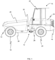
- an off-highway vehicle also known as a working machine, is illustrated and is indicated generally at 10.
- the off-highway vehicle 10 is a dumper vehicle.
- the off-highway vehicle or working machine may be selected from those used in construction industries (e.g. backhoe loaders, slew excavators telescopic handlers, forklifts, skid-steer loaders, dump trucks, bulldozers, graders), agricultural industries (e.g. tractors, combine harvesters, self-propelled harvesters and sprayers), quarrying (e.g. loading shovels, aggregate crushing equipment), and forestry (e.g. timber harvesters, feller bunchers).
- construction industries e.g. backhoe loaders, slew excavators telescopic handlers, forklifts, skid-steer loaders, dump trucks, bulldozers, graders
- agricultural industries e.g. tractors, combine harvesters, self-propelled harvesters and sprayers
- quarrying e.g. loading shovels, aggregate crushing equipment
- forestry e.g. timber harvesters
- the dumper vehicle 10 has a nominal laden capacity of 6 metric tonnes and a volume of heaped material (e.g. earth) of between 3.2-3.6m 3 and of flowable material (e.g. concrete) of approximately 2.0m 3 .
- the vehicle 10 includes a structural chassis frame 12 having a front end 14 and a rear end 16.
- the frame 12 has two sets of wheels mounted to the frame, two front wheels 18 mounted proximate the front end 14 of the frame 12, and two rear wheels 20 mounted proximate the rear end 16 of the frame 12.
- the frame 12 also has an operator seat mounted to the frame 12.
- the operator seat is located proximate to the rear wheels 20 along the longitudinal length of the frame 12.
- the operator seat is provided within an operator cab 22.
- an operator cab 22 may not be provided and a roll cage will be used instead.
- the dumper vehicle 10 includes a housing 24 for housing a diesel engine of an engine system.
- the housing 24, and so the engine, are located rearward of the cab 22 on the frame 12.
- the housing 24 forms the rear extent of the dumping vehicle 10.
- the engine system includes an after-treatment system so as to reduce the emissions of the engine system.
- the after-treatment system includes a DPF filter arranged in the exhaust flow path of the engine system so as to be capable of filtering particulate matter or soot from the engine exhaust gas.
- the engine system includes a sensor configured to monitor a fill state of the DPF and to generate a signal when the fill state of the DPF is at one or more pre-determined threshold levels.
- the container 26 is positioned such that a majority of the elongate length of the container 26 is situated between the front 18 and rear wheels 20.
- the container 26 is pivotally mounted to the frame 12, via two pivotable mounts (not shown), which enables the container 26 to be moveable or pivotable proximate the front of both the container 26 and the frame 12 between a transport position for transporting a load and a discharge position for discharging of a load.
- the frame 12 of the dumper vehicle 10 is provided in two parts that are able to articulate about at least a vertical axis with respect to each other. That is, the frame 12 includes a main chassis 28 and a front chassis 30.
- the operator seat and operator cab 22 are mounted to the main chassis 28.
- the container 26 is mounted to the front chassis 30.
- the main chassis 28 and the front chassis 30 are pivotally connected together via a linkage 32.
- the linkage 32 is such that the front chassis 30 is able to pivot or articulate about a vertical axis up to an angle of up to 35° with respect to the main chassis 28.
- a hydraulic system for the off-highway vehicle 10 is illustrated and is indicated generally at 34.
- the hydraulic system 34 includes a steering system 36 for steering the off-highway vehicle 10.
- the steering system 36 includes a hydraulic actuator 38 configured to pivot the front wheels 18 of the off-highway vehicle 10.
- the hydraulic system 34 includes a hydraulic actuator 40 configured to control a function of the off-highway vehicle 10.
- the hydraulic actuator 40 is configured to move or pivot the container 26 between the transport position for transporting a load and the discharge position for discharging of a load.
- the hydraulic system 34 includes a hydraulic actuator 42 configured to control a function of the off-highway vehicle 10.
- the hydraulic actuator 42 is configured to slew the container 26 about a substantially upright axis (i.e. slew about a substantially horizontal plane). In the illustrated arrangement, two hydraulic actuators 42 are provided for slewing the container 26. In alternative arrangements, only a single hydraulic actuator 42 may be provided, or the hydraulic actuators 42 may be omitted from the off-highway vehicle 10. In arrangements where the off-highway vehicle 10 is not a dumper vehicle, it will be appreciated that the off-highway vehicle will be provided with one or more hydraulic actuators configured to control one or more functions of the off-highway vehicle.
- the hydraulic system 34 includes a sump or reservoir 44 and a hydraulic circuit 46 defining a flow path for conveying hydraulic fluid to the hydraulic actuators 38, 40, 42.
- a hydraulic pump system 48 conveys a flow rate of hydraulic fluid along the hydraulic fluid circuit 46 to provide hydraulic fluid to the hydraulic actuators 38, 40, 42.
- the hydraulic pump system 48 includes a fixed displacement pump.
- the hydraulic pump system 48 may include multiple hydraulic pumps (e.g. a high displacement pump and a low displacement pump) configured to provide different rates of flow along the hydraulic circuit 46 to actuate the hydraulic actuators 38, 40, 42.
- the engine of the engine system drives the hydraulic pump system 48 in response to the demand or load from the hydraulic actuators 38, 40, 42. Whilst the hydraulic pump or pumps have been described as being a fixed hydraulic pump, it will be appreciated that in alternative arrangements the off-highway vehicle may include one or more variable hydraulic pumps.
- the hydraulic system 34 includes a first valve 50 provided along the hydraulic fluid circuit 46.
- the first valve 50 is moveable between an active state and an inactive state. In the active state, the first valve 50 is configured to divert hydraulic fluid flow from the hydraulic fluid circuit 46, such that a rate of hydraulic fluid flow is delivered to the steering actuator 38. Hydraulic fluid that is directed to the steering system 36 returns to the sump 44 after exiting the steering system 36.
- the first valve is priority valve 50.
- the priority valve is configured to ensure that even when hydraulic fluid is being directed to other hydraulic actuators of the off-highway vehicle 10, an amount of hydraulic fluid flow is directed to the steering actuator 38. This arrangement helps to ensure that steering of the off-highway vehicle 10 is always possible.
- the hydraulic system 34 includes a second valve 52 provided along the hydraulic fluid circuit 46.
- the second valve 52 is moveable between an active state and an inactive state. In the active state, the second valve 52 is configured to divert hydraulic fluid flow from the hydraulic fluid circuit 46, such that a rate of hydraulic fluid flow is delivered to the hydraulic actuator 40.
- the hydraulic system 34 includes a third valve 53 provided along the hydraulic fluid circuit 46.
- the third valve 53 is moveable between an active state and an inactive state. In the active state, the third valve 53 is configured to divert hydraulic fluid flow from the hydraulic fluid circuit 46, such that a rate of hydraulic fluid flow is delivered to the hydraulic actuator(s) 42. Hydraulic fluid that has been diverted from the hydraulic circuit 46 to hydraulic actuators 40, 42 subsequently returns to the hydraulic circuit 46.
- the hydraulic circuit 46 includes a bypass port or flow path 54 that extends from the second and or third valves 52, 53.
- the bypass port 54 is configured such that only hydraulic fluid that is not diverted to the hydraulic actuator 40 and or hydraulic actuator 42 flows along the bypass port 54.
- the bypass port 54 is positioned between the final valve on the hydraulic circuit 46 and the sump 44.
- a load valve 56 is positioned on the bypass port 54.
- the load valve 56 is moveable between an active state and an inactive state. In the active state, the load valve 56 is configured induce a hydraulic load on the hydraulic system 34. Put another way, in an active state, the load valve 56 is configured to induce a parasitic load on the hydraulic system 34.
- the engine system 58 includes a diesel engine 60.
- the engine 60 is configured to power the wheels 18, 20 to propel the off-highway vehicle 10.
- the engine 60 is configured to power the hydraulic system 34.
- a DPF 64 is installed along the exhaust duct 62.
- the engine system includes a sensor (not shown) configured to monitor a fill state of the DPF 64.
- the engine system 58 generates a signal when the fill state of the DPF 64 is at or above different threshold values.
- the engine system 58 includes a control system 66.
- the control system 66 includes a controller configured to receive the signal from the engine system 58 corresponding to a fill state of the DPF 64.
- the controller When the controller receives a signal corresponding to the fill state of the DPF 64 being at or above a first threshold level or value, the controller selectively induces a parasitic load on the engine 60 to increase the operating temperature of the engine 60. This increased operating temperature raises the temperature of the DPR 64 so as to become more favourable to regenerating the DPF 64 during natural operation of the off-highway vehicle 10.
- the controller is configured to selectively actuate the hydraulic load valve 56 to induce the parasitic load.
- the engine 60 has a maximum rated power output and the parasitic load is less than 10% of the maximum rated power output, but may be less than 5% of the maximum rated power output. It will be understood that the parasitic load induced should be minimised to reduce excessive fuel consumption.
- the control system 66 is configured to induce the minimal required parasitic load that is sufficient to ensure regeneration is successful.
- the controller of the control system 66 is configured to selectively remove the parasitic load on the engine 60 under different conditions.
- the controller may remove the parasitic load when: an operator demanded engine speed is above a predetermined engine speed; an operator demanded engine power is above a predetermined engine power; a signal is received by the controller corresponding to a fill state of the DPF 64 being at or above a second threshold, greater than the first threshold; a signal is received by the controller corresponding to a fill state of the DPF 64 being below the first threshold; or an exhaust gas temperature of the engine 60 is above a predetermined temperature.
- the controller is configured to selectively induce the parasitic load on the engine 60 by increasing the engine speed.
- the controller may increase the engine speed in the range 1400-1800 RPM, for example approximately 1600 RPM.
- the controller is configured to selectively increase the engine speed in response to receiving a signal corresponding to a fill state of the DPF 64 being at or above a second threshold, which greater than the first threshold.
- the controller of the control system 66 is configured to selectively remove the increased engine speed demand on the engine 60 under different conditions.
- the controller may remove the increased engine speed demand: upon receipt by the controller of a signal indicative of an operator demand to move the vehicle; upon receipt by the controller of a signal indicative of an operator demand to power one of the hydraulic actuators; when a signal is received by the controller corresponding to a fill state of the DPF below a second threshold; when an exhaust gas temperature of the engine is above a pre-determined temperature.
- the controller may be configured to only enable the increased engine speed demand to occur when the off-highway vehicle 10 is stationary.
- the controller may be configured to receive a signal corresponding to a stationary state of the off-highway vehicle 10, and to only induce the engine speed parasitic load when the off-highway vehicle 10 is in the stationary state.
- the stationary state of the off-highway vehicle may be generated through one or more of the off-highway vehicle has a travelling speed of approximately zero, the off-highway vehicle is in neutral, or a parking brake of the off-highway vehicle has been actuated, or through any other suitable condition of the off-highway vehicle 10.
- the engine system 58 emits a signal.
- the controller is configured to receive the signal corresponding to a fill state of the DPF 64 being at or above the third threshold and to limit the power output of the engine 60.
- the controller may be configured to set a maximum engine speed in the range 1000-1400 RPM, for example approximately 1200 RPM.
- the engine system 58 emits a signal.
- the controller is configured to receive the signal corresponding to a fill state of the DPF 64 being at or above the fourth threshold and to prevent operation of the off-highway vehicle 10 in response to receiving the signal.
Landscapes
- Engineering & Computer Science (AREA)
- General Engineering & Computer Science (AREA)
- Chemical & Material Sciences (AREA)
- Combustion & Propulsion (AREA)
- Mechanical Engineering (AREA)
- Mining & Mineral Resources (AREA)
- Civil Engineering (AREA)
- Structural Engineering (AREA)
- Chemical Kinetics & Catalysis (AREA)
- Processes For Solid Components From Exhaust (AREA)
- Control Of Vehicle Engines Or Engines For Specific Uses (AREA)
Applications Claiming Priority (1)
| Application Number | Priority Date | Filing Date | Title |
|---|---|---|---|
| GB2013469.8A GB2598352B (en) | 2020-08-27 | 2020-08-27 | A control system |
Publications (2)
| Publication Number | Publication Date |
|---|---|
| EP3971403A2 true EP3971403A2 (de) | 2022-03-23 |
| EP3971403A3 EP3971403A3 (de) | 2022-06-01 |
Family
ID=72749687
Family Applications (1)
| Application Number | Title | Priority Date | Filing Date |
|---|---|---|---|
| EP21192221.6A Pending EP3971403A3 (de) | 2020-08-27 | 2021-08-19 | Steuerung eines dieselrussfiltersystems |
Country Status (3)
| Country | Link |
|---|---|
| US (1) | US11608792B2 (de) |
| EP (1) | EP3971403A3 (de) |
| GB (1) | GB2598352B (de) |
Citations (1)
| Publication number | Priority date | Publication date | Assignee | Title |
|---|---|---|---|---|
| EP2516824B1 (de) * | 2009-12-22 | 2022-02-16 | Perkins Engines Company Limited | Übergangszeit bri der partikelfilterregenerationsunterstützung |
Family Cites Families (27)
| Publication number | Priority date | Publication date | Assignee | Title |
|---|---|---|---|---|
| US20050155345A1 (en) * | 2002-03-29 | 2005-07-21 | Tokyo Electron Limited | Device and method for purifying exhaust gas from industrial vehicle engine |
| JP2004137968A (ja) * | 2002-10-17 | 2004-05-13 | Toyota Industries Corp | 産業車両用エンジンの排気浄化装置および排気浄化方法 |
| US7623953B2 (en) * | 2005-06-08 | 2009-11-24 | Caterpillar Inc. | Integrated regeneration and engine controls |
| US7523606B2 (en) * | 2005-08-31 | 2009-04-28 | Caterpillar Inc. | Parasitic load control system for exhaust temperature control |
| US7798277B2 (en) * | 2007-05-31 | 2010-09-21 | Caterpillar Inc | Machine retarder |
| WO2009060719A1 (ja) * | 2007-11-06 | 2009-05-14 | Hitachi Construction Machinery Co., Ltd. | 作業車両の排気ガス浄化システム |
| JP2009191654A (ja) * | 2008-02-12 | 2009-08-27 | Hino Motors Ltd | パティキュレートフィルタの再生方法 |
| JP2009264315A (ja) * | 2008-04-28 | 2009-11-12 | Yanmar Co Ltd | 排気ガス浄化装置 |
| JP5101436B2 (ja) * | 2008-08-26 | 2012-12-19 | ヤンマー株式会社 | ディーゼルエンジン |
| JP4774096B2 (ja) * | 2008-11-17 | 2011-09-14 | 日立建機株式会社 | 作業機械の排気ガス浄化システム |
| CN101608648B (zh) * | 2009-07-06 | 2011-04-06 | 三一重工股份有限公司 | 获取液压泵的排量控制机构特性参数的方法和检测装置 |
| JP2011163250A (ja) * | 2010-02-12 | 2011-08-25 | Mitsubishi Heavy Ind Ltd | 内燃機関の排気ガス処理方法及び装置 |
| JP5230674B2 (ja) * | 2010-03-10 | 2013-07-10 | 日立建機株式会社 | 作業機械の排気ガス処理装置 |
| DE102010003158A1 (de) * | 2010-03-23 | 2012-02-16 | Deere & Company | Vorrichtung zur Durchführung eines Regenerationsvorgangs in einem Rußpartikelfilter |
| JP5548882B2 (ja) * | 2010-08-27 | 2014-07-16 | 日立建機株式会社 | 作業車両の排気ガス浄化システム |
| JP5539116B2 (ja) * | 2010-08-31 | 2014-07-02 | 日立建機株式会社 | 油圧作業機 |
| KR101787803B1 (ko) * | 2010-08-31 | 2017-10-18 | 히다찌 겐끼 가부시키가이샤 | 작업 기계 |
| CN103270265B (zh) * | 2010-12-22 | 2016-01-20 | 斗山英维高株式会社 | 利用非工作负载的柴油微粒过滤器强制再生系统及其方法 |
| US8820057B2 (en) * | 2011-03-30 | 2014-09-02 | Deere & Company | Increased fan speed to assist DPF regeneration |
| JP5658075B2 (ja) * | 2011-04-15 | 2015-01-21 | 日立建機株式会社 | 作業機の排気浄化システム |
| US9534551B2 (en) * | 2011-09-27 | 2017-01-03 | Kubota Corporation | Working machine |
| GB201204419D0 (en) * | 2012-03-13 | 2012-04-25 | Jaguar Cars | Regeneration of diesel particle filter |
| CN104903595B (zh) * | 2013-01-08 | 2017-03-08 | 日立建机株式会社 | 工作机械的液压系统 |
| US20160069291A1 (en) * | 2014-09-09 | 2016-03-10 | Caterpillar Inc. | Hybrid powertrain and method of operating same |
| JP6957380B2 (ja) * | 2018-02-07 | 2021-11-02 | 住友重機械建機クレーン株式会社 | 作業機械 |
| DE102018109568A1 (de) * | 2018-04-20 | 2019-10-24 | Wacker Neuson Linz Gmbh | Arbeitsfahrzeug mit einem Hydraulikkreislauf mit bedarfsweise aktivierbarem Strömungswiderstand |
| US10794306B2 (en) * | 2019-01-25 | 2020-10-06 | Caterpillar Inc. | Exhaust temperature maintenance using a parasitic load |
-
2020
- 2020-08-27 GB GB2013469.8A patent/GB2598352B/en active Active
-
2021
- 2021-08-19 EP EP21192221.6A patent/EP3971403A3/de active Pending
- 2021-08-27 US US17/460,157 patent/US11608792B2/en active Active
Patent Citations (1)
| Publication number | Priority date | Publication date | Assignee | Title |
|---|---|---|---|---|
| EP2516824B1 (de) * | 2009-12-22 | 2022-02-16 | Perkins Engines Company Limited | Übergangszeit bri der partikelfilterregenerationsunterstützung |
Also Published As
| Publication number | Publication date |
|---|---|
| GB202013469D0 (en) | 2020-10-14 |
| EP3971403A3 (de) | 2022-06-01 |
| US11608792B2 (en) | 2023-03-21 |
| GB2598352A (en) | 2022-03-02 |
| US20220065183A1 (en) | 2022-03-03 |
| GB2598352B (en) | 2024-07-17 |
Similar Documents
| Publication | Publication Date | Title |
|---|---|---|
| CN103597178B (zh) | 工程机械 | |
| JP5845285B2 (ja) | 建設機械 | |
| CN104066940B (zh) | 工程机械 | |
| US20120279203A1 (en) | Exhaust gas purification system for hydraulic operating machine | |
| US9593630B2 (en) | Engine output control device for a construction machine | |
| US20120204537A1 (en) | Adaptive diesel particulate filter regeneration control and method | |
| WO2014188997A1 (ja) | 建設機械 | |
| CN103987930A (zh) | 工程机械 | |
| CN103764922B (zh) | 工程机械 | |
| KR102627826B1 (ko) | 작업 차량 | |
| US11608792B2 (en) | Control system | |
| JP5714300B2 (ja) | 排気ガス浄化システム | |
| CN105189953B (zh) | 工程机械 | |
| GB2576295A (en) | A control system | |
| JP5486426B2 (ja) | 作業用車両の排ガス浄化装置 | |
| JP6692672B2 (ja) | アスファルトフィニッシャ | |
| KR20210138281A (ko) | 건설기계의 dpf 재생 시스템 | |
| CN110770425B (zh) | 用于控制车辆推进系统的方法 | |
| JP2021088935A (ja) | エンジン式産業車両 | |
| JP6615668B2 (ja) | アスファルトフィニッシャ | |
| CN112709646B (zh) | 超低怠速管理 | |
| JP2023006692A (ja) | 建設機械 |
Legal Events
| Date | Code | Title | Description |
|---|---|---|---|
| PUAI | Public reference made under article 153(3) epc to a published international application that has entered the european phase |
Free format text: ORIGINAL CODE: 0009012 |
|
| STAA | Information on the status of an ep patent application or granted ep patent |
Free format text: STATUS: THE APPLICATION HAS BEEN PUBLISHED |
|
| AK | Designated contracting states |
Kind code of ref document: A2 Designated state(s): AL AT BE BG CH CY CZ DE DK EE ES FI FR GB GR HR HU IE IS IT LI LT LU LV MC MK MT NL NO PL PT RO RS SE SI SK SM TR |
|
| PUAL | Search report despatched |
Free format text: ORIGINAL CODE: 0009013 |
|
| AK | Designated contracting states |
Kind code of ref document: A3 Designated state(s): AL AT BE BG CH CY CZ DE DK EE ES FI FR GB GR HR HU IE IS IT LI LT LU LV MC MK MT NL NO PL PT RO RS SE SI SK SM TR |
|
| RIC1 | Information provided on ipc code assigned before grant |
Ipc: F01N 11/00 20060101ALI20220425BHEP Ipc: E02F 3/04 20060101ALI20220425BHEP Ipc: F15B 13/00 20060101ALI20220425BHEP Ipc: F15B 21/00 20060101ALI20220425BHEP Ipc: F15B 11/00 20060101ALI20220425BHEP Ipc: F01N 9/00 20060101ALI20220425BHEP Ipc: F01N 3/021 20060101ALI20220425BHEP Ipc: E02F 9/20 20060101ALI20220425BHEP Ipc: F02D 41/22 20060101ALI20220425BHEP Ipc: F02D 29/04 20060101ALI20220425BHEP Ipc: F02D 41/02 20060101AFI20220425BHEP |
|
| STAA | Information on the status of an ep patent application or granted ep patent |
Free format text: STATUS: REQUEST FOR EXAMINATION WAS MADE |
|
| 17P | Request for examination filed |
Effective date: 20221128 |
|
| RBV | Designated contracting states (corrected) |
Designated state(s): AL AT BE BG CH CY CZ DE DK EE ES FI FR GB GR HR HU IE IS IT LI LT LU LV MC MK MT NL NO PL PT RO RS SE SI SK SM TR |
|
| STAA | Information on the status of an ep patent application or granted ep patent |
Free format text: STATUS: EXAMINATION IS IN PROGRESS |
|
| 17Q | First examination report despatched |
Effective date: 20240221 |
|
| P01 | Opt-out of the competence of the unified patent court (upc) registered |
Free format text: CASE NUMBER: APP_53/2025 Effective date: 20250102 |
|
| RIC1 | Information provided on ipc code assigned before grant |
Ipc: F02D 41/02 20060101AFI20250709BHEP Ipc: F02D 29/04 20060101ALI20250709BHEP Ipc: F02D 41/22 20060101ALI20250709BHEP Ipc: E02F 9/20 20060101ALI20250709BHEP Ipc: F01N 3/021 20060101ALI20250709BHEP Ipc: F01N 9/00 20060101ALI20250709BHEP Ipc: F15B 11/00 20060101ALI20250709BHEP Ipc: F15B 21/00 20060101ALI20250709BHEP Ipc: F15B 13/00 20060101ALI20250709BHEP Ipc: E02F 3/04 20060101ALI20250709BHEP Ipc: F01N 11/00 20060101ALI20250709BHEP Ipc: E02F 9/22 20060101ALI20250709BHEP Ipc: F01N 3/023 20060101ALI20250709BHEP |
|
| GRAP | Despatch of communication of intention to grant a patent |
Free format text: ORIGINAL CODE: EPIDOSNIGR1 |
|
| STAA | Information on the status of an ep patent application or granted ep patent |
Free format text: STATUS: GRANT OF PATENT IS INTENDED |
|
| INTG | Intention to grant announced |
Effective date: 20250828 |
|
| GRAJ | Information related to disapproval of communication of intention to grant by the applicant or resumption of examination proceedings by the epo deleted |
Free format text: ORIGINAL CODE: EPIDOSDIGR1 |
|
| STAA | Information on the status of an ep patent application or granted ep patent |
Free format text: STATUS: EXAMINATION IS IN PROGRESS |
|
| INTC | Intention to grant announced (deleted) |