EP3962857B1 - Verfahren zur herstellung von schwefel und schwefelsäure - Google Patents
Verfahren zur herstellung von schwefel und schwefelsäure Download PDFInfo
- Publication number
- EP3962857B1 EP3962857B1 EP20720326.6A EP20720326A EP3962857B1 EP 3962857 B1 EP3962857 B1 EP 3962857B1 EP 20720326 A EP20720326 A EP 20720326A EP 3962857 B1 EP3962857 B1 EP 3962857B1
- Authority
- EP
- European Patent Office
- Prior art keywords
- claus
- sulfuric acid
- gas
- reaction furnace
- tail gas
- Prior art date
- Legal status (The legal status is an assumption and is not a legal conclusion. Google has not performed a legal analysis and makes no representation as to the accuracy of the status listed.)
- Active
Links
Images

Classifications
-
- C—CHEMISTRY; METALLURGY
- C01—INORGANIC CHEMISTRY
- C01B—NON-METALLIC ELEMENTS; COMPOUNDS THEREOF; METALLOIDS OR COMPOUNDS THEREOF NOT COVERED BY SUBCLASS C01C
- C01B17/00—Sulfur; Compounds thereof
- C01B17/02—Preparation of sulfur; Purification
- C01B17/04—Preparation of sulfur; Purification from gaseous sulfur compounds including gaseous sulfides
- C01B17/0404—Preparation of sulfur; Purification from gaseous sulfur compounds including gaseous sulfides by processes comprising a dry catalytic conversion of hydrogen sulfide-containing gases, e.g. the Claus process
-
- B—PERFORMING OPERATIONS; TRANSPORTING
- B01—PHYSICAL OR CHEMICAL PROCESSES OR APPARATUS IN GENERAL
- B01D—SEPARATION
- B01D53/00—Separation of gases or vapours; Recovering vapours of volatile solvents from gases; Chemical or biological purification of waste gases, e.g. engine exhaust gases, smoke, fumes, flue gases, aerosols
- B01D53/14—Separation of gases or vapours; Recovering vapours of volatile solvents from gases; Chemical or biological purification of waste gases, e.g. engine exhaust gases, smoke, fumes, flue gases, aerosols by absorption
- B01D53/1456—Removing acid components
- B01D53/1481—Removing sulfur dioxide or sulfur trioxide
-
- B—PERFORMING OPERATIONS; TRANSPORTING
- B01—PHYSICAL OR CHEMICAL PROCESSES OR APPARATUS IN GENERAL
- B01D—SEPARATION
- B01D53/00—Separation of gases or vapours; Recovering vapours of volatile solvents from gases; Chemical or biological purification of waste gases, e.g. engine exhaust gases, smoke, fumes, flue gases, aerosols
- B01D53/14—Separation of gases or vapours; Recovering vapours of volatile solvents from gases; Chemical or biological purification of waste gases, e.g. engine exhaust gases, smoke, fumes, flue gases, aerosols by absorption
- B01D53/1493—Selection of liquid materials for use as absorbents
-
- B—PERFORMING OPERATIONS; TRANSPORTING
- B01—PHYSICAL OR CHEMICAL PROCESSES OR APPARATUS IN GENERAL
- B01D—SEPARATION
- B01D53/00—Separation of gases or vapours; Recovering vapours of volatile solvents from gases; Chemical or biological purification of waste gases, e.g. engine exhaust gases, smoke, fumes, flue gases, aerosols
- B01D53/34—Chemical or biological purification of waste gases
- B01D53/46—Removing components of defined structure
- B01D53/48—Sulfur compounds
- B01D53/52—Hydrogen sulfide
- B01D53/523—Mixtures of hydrogen sulfide and sulfur oxides
-
- B—PERFORMING OPERATIONS; TRANSPORTING
- B01—PHYSICAL OR CHEMICAL PROCESSES OR APPARATUS IN GENERAL
- B01D—SEPARATION
- B01D53/00—Separation of gases or vapours; Recovering vapours of volatile solvents from gases; Chemical or biological purification of waste gases, e.g. engine exhaust gases, smoke, fumes, flue gases, aerosols
- B01D53/34—Chemical or biological purification of waste gases
- B01D53/74—General processes for purification of waste gases; Apparatus or devices specially adapted therefor
- B01D53/86—Catalytic processes
- B01D53/8603—Removing sulfur compounds
- B01D53/8612—Hydrogen sulfide
- B01D53/8615—Mixtures of hydrogen sulfide and sulfur oxides
-
- B—PERFORMING OPERATIONS; TRANSPORTING
- B01—PHYSICAL OR CHEMICAL PROCESSES OR APPARATUS IN GENERAL
- B01J—CHEMICAL OR PHYSICAL PROCESSES, e.g. CATALYSIS OR COLLOID CHEMISTRY; THEIR RELEVANT APPARATUS
- B01J19/00—Chemical, physical or physico-chemical processes in general; Their relevant apparatus
- B01J19/0006—Controlling or regulating processes
- B01J19/0013—Controlling the temperature of the process
-
- B—PERFORMING OPERATIONS; TRANSPORTING
- B01—PHYSICAL OR CHEMICAL PROCESSES OR APPARATUS IN GENERAL
- B01J—CHEMICAL OR PHYSICAL PROCESSES, e.g. CATALYSIS OR COLLOID CHEMISTRY; THEIR RELEVANT APPARATUS
- B01J19/00—Chemical, physical or physico-chemical processes in general; Their relevant apparatus
- B01J19/24—Stationary reactors without moving elements inside
- B01J19/2405—Stationary reactors without moving elements inside provoking a turbulent flow of the reactants, such as in cyclones, or having a high Reynolds-number
-
- B—PERFORMING OPERATIONS; TRANSPORTING
- B01—PHYSICAL OR CHEMICAL PROCESSES OR APPARATUS IN GENERAL
- B01J—CHEMICAL OR PHYSICAL PROCESSES, e.g. CATALYSIS OR COLLOID CHEMISTRY; THEIR RELEVANT APPARATUS
- B01J19/00—Chemical, physical or physico-chemical processes in general; Their relevant apparatus
- B01J19/24—Stationary reactors without moving elements inside
- B01J19/2455—Stationary reactors without moving elements inside provoking a loop type movement of the reactants
- B01J19/2465—Stationary reactors without moving elements inside provoking a loop type movement of the reactants externally, i.e. the mixture leaving the vessel and subsequently re-entering it
-
- C—CHEMISTRY; METALLURGY
- C01—INORGANIC CHEMISTRY
- C01B—NON-METALLIC ELEMENTS; COMPOUNDS THEREOF; METALLOIDS OR COMPOUNDS THEREOF NOT COVERED BY SUBCLASS C01C
- C01B17/00—Sulfur; Compounds thereof
- C01B17/02—Preparation of sulfur; Purification
- C01B17/0253—Preparation of sulfur; Purification from non-gaseous sulfur compounds other than sulfides or materials containing such sulfides
-
- C—CHEMISTRY; METALLURGY
- C01—INORGANIC CHEMISTRY
- C01B—NON-METALLIC ELEMENTS; COMPOUNDS THEREOF; METALLOIDS OR COMPOUNDS THEREOF NOT COVERED BY SUBCLASS C01C
- C01B17/00—Sulfur; Compounds thereof
- C01B17/02—Preparation of sulfur; Purification
- C01B17/04—Preparation of sulfur; Purification from gaseous sulfur compounds including gaseous sulfides
- C01B17/0404—Preparation of sulfur; Purification from gaseous sulfur compounds including gaseous sulfides by processes comprising a dry catalytic conversion of hydrogen sulfide-containing gases, e.g. the Claus process
- C01B17/0447—Separation of the obtained sulfur
-
- C—CHEMISTRY; METALLURGY
- C01—INORGANIC CHEMISTRY
- C01B—NON-METALLIC ELEMENTS; COMPOUNDS THEREOF; METALLOIDS OR COMPOUNDS THEREOF NOT COVERED BY SUBCLASS C01C
- C01B17/00—Sulfur; Compounds thereof
- C01B17/02—Preparation of sulfur; Purification
- C01B17/04—Preparation of sulfur; Purification from gaseous sulfur compounds including gaseous sulfides
- C01B17/0404—Preparation of sulfur; Purification from gaseous sulfur compounds including gaseous sulfides by processes comprising a dry catalytic conversion of hydrogen sulfide-containing gases, e.g. the Claus process
- C01B17/0452—Process control; Start-up or cooling-down procedures of the Claus process
-
- C—CHEMISTRY; METALLURGY
- C01—INORGANIC CHEMISTRY
- C01B—NON-METALLIC ELEMENTS; COMPOUNDS THEREOF; METALLOIDS OR COMPOUNDS THEREOF NOT COVERED BY SUBCLASS C01C
- C01B17/00—Sulfur; Compounds thereof
- C01B17/02—Preparation of sulfur; Purification
- C01B17/04—Preparation of sulfur; Purification from gaseous sulfur compounds including gaseous sulfides
- C01B17/0404—Preparation of sulfur; Purification from gaseous sulfur compounds including gaseous sulfides by processes comprising a dry catalytic conversion of hydrogen sulfide-containing gases, e.g. the Claus process
- C01B17/0456—Preparation of sulfur; Purification from gaseous sulfur compounds including gaseous sulfides by processes comprising a dry catalytic conversion of hydrogen sulfide-containing gases, e.g. the Claus process the hydrogen sulfide-containing gas being a Claus process tail gas
-
- C—CHEMISTRY; METALLURGY
- C01—INORGANIC CHEMISTRY
- C01B—NON-METALLIC ELEMENTS; COMPOUNDS THEREOF; METALLOIDS OR COMPOUNDS THEREOF NOT COVERED BY SUBCLASS C01C
- C01B17/00—Sulfur; Compounds thereof
- C01B17/69—Sulfur trioxide; Sulfuric acid
- C01B17/74—Preparation
- C01B17/76—Preparation by contact processes
- C01B17/775—Liquid phase contacting processes or wet catalysis processes
-
- C—CHEMISTRY; METALLURGY
- C01—INORGANIC CHEMISTRY
- C01B—NON-METALLIC ELEMENTS; COMPOUNDS THEREOF; METALLOIDS OR COMPOUNDS THEREOF NOT COVERED BY SUBCLASS C01C
- C01B17/00—Sulfur; Compounds thereof
- C01B17/69—Sulfur trioxide; Sulfuric acid
- C01B17/74—Preparation
- C01B17/76—Preparation by contact processes
- C01B17/80—Apparatus
- C01B17/806—Absorbers; Heat exchangers
-
- F—MECHANICAL ENGINEERING; LIGHTING; HEATING; WEAPONS; BLASTING
- F23—COMBUSTION APPARATUS; COMBUSTION PROCESSES
- F23C—METHODS OR APPARATUS FOR COMBUSTION USING FLUID FUEL OR SOLID FUEL SUSPENDED IN A CARRIER GAS OR AIR
- F23C6/00—Combustion apparatus characterised by the combination of two or more combustion chambers or combustion zones, e.g. for staged combustion
- F23C6/04—Combustion apparatus characterised by the combination of two or more combustion chambers or combustion zones, e.g. for staged combustion in series connection
- F23C6/042—Combustion apparatus characterised by the combination of two or more combustion chambers or combustion zones, e.g. for staged combustion in series connection with fuel supply in stages
-
- F—MECHANICAL ENGINEERING; LIGHTING; HEATING; WEAPONS; BLASTING
- F23—COMBUSTION APPARATUS; COMBUSTION PROCESSES
- F23G—CREMATION FURNACES; CONSUMING WASTE PRODUCTS BY COMBUSTION
- F23G7/00—Incinerators or other apparatus for consuming industrial waste, e.g. chemicals
- F23G7/06—Incinerators or other apparatus for consuming industrial waste, e.g. chemicals of waste gases or noxious gases, e.g. exhaust gases
-
- B—PERFORMING OPERATIONS; TRANSPORTING
- B01—PHYSICAL OR CHEMICAL PROCESSES OR APPARATUS IN GENERAL
- B01D—SEPARATION
- B01D2255/00—Catalysts
- B01D2255/20—Metals or compounds thereof
- B01D2255/207—Transition metals
- B01D2255/20723—Vanadium
-
- B—PERFORMING OPERATIONS; TRANSPORTING
- B01—PHYSICAL OR CHEMICAL PROCESSES OR APPARATUS IN GENERAL
- B01J—CHEMICAL OR PHYSICAL PROCESSES, e.g. CATALYSIS OR COLLOID CHEMISTRY; THEIR RELEVANT APPARATUS
- B01J2219/00—Chemical, physical or physico-chemical processes in general; Their relevant apparatus
- B01J2219/00049—Controlling or regulating processes
- B01J2219/00051—Controlling the temperature
- B01J2219/00157—Controlling the temperature by means of a burner
-
- C—CHEMISTRY; METALLURGY
- C01—INORGANIC CHEMISTRY
- C01P—INDEXING SCHEME RELATING TO STRUCTURAL AND PHYSICAL ASPECTS OF SOLID INORGANIC COMPOUNDS
- C01P2006/00—Physical properties of inorganic compounds
- C01P2006/80—Compositional purity
-
- F—MECHANICAL ENGINEERING; LIGHTING; HEATING; WEAPONS; BLASTING
- F23—COMBUSTION APPARATUS; COMBUSTION PROCESSES
- F23G—CREMATION FURNACES; CONSUMING WASTE PRODUCTS BY COMBUSTION
- F23G2209/00—Specific waste
- F23G2209/14—Gaseous waste or fumes
-
- Y—GENERAL TAGGING OF NEW TECHNOLOGICAL DEVELOPMENTS; GENERAL TAGGING OF CROSS-SECTIONAL TECHNOLOGIES SPANNING OVER SEVERAL SECTIONS OF THE IPC; TECHNICAL SUBJECTS COVERED BY FORMER USPC CROSS-REFERENCE ART COLLECTIONS [XRACs] AND DIGESTS
- Y02—TECHNOLOGIES OR APPLICATIONS FOR MITIGATION OR ADAPTATION AGAINST CLIMATE CHANGE
- Y02P—CLIMATE CHANGE MITIGATION TECHNOLOGIES IN THE PRODUCTION OR PROCESSING OF GOODS
- Y02P20/00—Technologies relating to chemical industry
- Y02P20/10—Process efficiency
- Y02P20/129—Energy recovery, e.g. by cogeneration, H2recovery or pressure recovery turbines
Definitions
- the present invention is related to a process for conversion of H 2 S to elemental sulfur and sulfuric acid, optionally with an adjustable ratio between elemental sulfur and sulfuric acid.
- H 2 S is a common side product in many processes, including hydrodesulfurization of refinery streams and production of viscose. It is desirable to convert H 2 S prior to emission to the atmosphere as H 2 S is highly toxic, odorous and an environmental challenge.
- Refinery processes besides producing the well-known high concentration H 2 S gas, may often also produce a so-called sour water stripper gas, which comprises H 2 S, H 2 O and NH 3 in roughly equal molar amounts.
- the chosen process for H 2 S abatement has been the Claus process, which has been known and optimized for more the 8 decades.
- the Claus process proceeds by sub-stoichiometric combustion of H 2 S producing SO 2 in a Claus reaction furnace, providing a Claus converter feed gas.
- the subsequent Claus process stages convert H 2 S and SO 2 to form elemental sulfur, which may be condensed and withdrawn.
- the sulfur removal efficiency of the Claus process is 95% to 98%, which is insufficient for environmental compliance. Therefore, it is common practice to provide a tail gas treatment after the Claus process to provide sulfur abatement above 99%.
- the tail gas treatment is sometimes a sulfuric acid plant, which introduces the requirement for handling of sulfuric acid.
- the sulfuric acid may be recycled to the Claus reaction furnace, where it may contribute to the formation of sulfur, and in addition provide opportunities for optimization of the Claus process equipment sizing and operation costs.
- H 2 SO 4 product is not always desired and it is suggested to recycle the sulfuric acid to an upstream Claus reaction furnace or the H 2 S oxidation step as described above.
- the recycling of sulfuric acid is merely thought as an abatement of sulfuric acid, and the consequences of recycling the H 2 SO 4 on the wet sulfuric acid or Claus process have not been evaluated, i.e. it is not recognized that H 2 SO 4 recirculation makes it possible to reduce the amount of O 2 (in the form of air, enriched air or pure oxygen) directed to the Claus reaction furnace, nor are the beneficial effects on the Claus and sulfuric acid processes realized.
- support fuel may be required in both the Claus reaction furnace and H 2 S oxidation step to obtain the desired operating temperature, without realizing the beneficial effects of using feedstock gases as support fuel for the H 2 S oxidation in the sulfuric acid process.
- WO 2017/220655 A1 also discloses a process combining a Claus plant and a SNOX/WSA plant without details on the Claus furnace.
- US 4,208,192A and US 4,070,424A relate to addition minute amounts of sulfuric acid to a flue gas at low temperatures, with the objective of conditioning the flue gas for an electrostatic precipitator.
- a process for conversion of H 2 S to elemental sulfur with increased efficiency in which a Claus process is combined with a sulfuric acid process.
- sulfuric acid produced in the sulfuric acid process, treating the Claus tail gas is recycled to the Claus reaction furnace for decomposition and elemental sulfur production.
- a stoichiometric amount of oxygen shall be defined under the assumption that the products derived from N, H, C, S and O in the feed gas are N 2 , H 2 O, CO 2 and SO 2 . If less than a stoichiometric amount of oxygen is present (also called sub-stoichiometric), this means that not all feed components are fully oxidized. For a Claus gas feed, this means that the process gas after sub-stoichiometric combustion/reaction may contain unconverted H 2 S, NH 3 and hydrocarbons from the feed stream(s) and H 2 , CO, COS and CS 2 formed in the O 2 deficient environment.
- a fuel shall be defined as a substance having a composition which, when oxidized with O 2 will form N 2 , H 2 O, CO 2 and SO 2 as the reaction product and release a substantial amount of energy by the reactions.
- a mixture of hydrocarbons e.g. natural gas, with CH 4 and C 2 H 6
- H 2 S is a typical fuel gas, but the fuel gas could also comprise CO, NH 3 and H 2 .
- oxygen is understood as a stream containing O 2 , such as air, enriched air and pure oxygen, but could also be another gas containing O 2 .
- the present invention relates to a process for production of sulfur from a feedstock gas comprising from 15%, 20%, 30 vol%, 40 vol% or 50% to 99 vol% or 100 vol% H 2 S and a stream of sulfuric acid involving the steps of
- At least an amount of the sulfuric acid is directed to said Claus reaction furnace via at least one pneumatic nozzle, receiving sulfuric acid and an atomization medium, with the associated benefit of such a nozzle forming small droplets, suitable for fast evaporation.
- Pneumatic nozzles are also known to the skilled person under the terms two fluid nozzles or two-phase nozzles.
- the atomization medium is compressed air and the flow is from 25 Nm 3 air/ton acid or 50 Nm 3 air/ton acid to 200 Nm 3 air/ton acid or 500 Nm 3 air/ton acid with the associated benefit of such a nozzle operating under these parameters forming small droplets, with low consumption of atomization media.
- At least an amount of the sulfuric acid is directed to said Claus reaction furnace via at least one hydraulic nozzle, designed for formation of small droplets, with the associated benefit of a hydraulic nozzle being simple to operate while providing sufficiently small droplets, without diluting the process gas with any atomization media
- the average process gas residence time in the Claus reaction furnace is less than 5 seconds, more preferably less than 2 seconds, with the associated benefit of such a reaction furnace having an appropriate size, while allowing sufficient time for evaporation of sulfuric acid droplets as well as the required partial chemical conversion of H 2 S and SO 2 to elemental sulfur
- the Claus reaction furnace comprises one or more turbulence enhancer(s), with the associated benefit of narrowing the residence time, temperature and gas composition distribution in the Claus reaction furnace.
- the Claus reaction furnace comprises a means of impaction, such as an impaction wall or a volume packed with inert material, with the associated benefit of destroying droplets by collision, to ensure absence of liquid H 2 SO 4 in the Claus converter feed gas.
- the Claus reaction furnace feedstock gas comprises less than 0.1 vol% non-elemental nitrogen, such as NH 3 , with the associated benefit of avoiding formation of e.g. ammonium salts which may plug the Claus condenser(s).
- the Claus reaction furnace feed stream comprises less than 50%, 20%, 10% or 1% elemental nitrogen with the associated benefit of providing a process with a high temperature in the Claus reaction furnace, and a reduced process gas volume, due to the reduced presence of N 2 , while avoiding excessive temperatures downstream as the evaporation of sulfuric acid cools the process gas.
- This can be accomplished by using pure O 2 or oxygen enriched air as the oxygen source.
- steps d and e are carried out sequentially 2-5 times, with the associated benefit of enabling a higher conversion in the process
- the H 2 S:SO 2 ratio of said Claus converter feed gas is below 4:1, 3:1 or 2:1, with the associated benefit of such a feed gas providing a H 2 S containing Claus tail gas to the Claus tail gas combustor, minimizing the need for fuel gas addition as the H 2 S oxidation releases a substantial amount of energy, whereas SO 2 does not release energy in the Claus tail gas combustor.
- the H 2 S:SO 2 ratio of said Claus converter gas is below 1.6:1, 1.8:1 or 2:1, with the associated benefit of having a substantially H 2 S free Claus tail gas.
- this can be an advantage as the SO 2 will not oxidize without a SO 2 conversion catalyst and thus it will be possible to preheat the Claus tail gas with a combination of catalytic H 2 S oxidation (controlled bypass of feedstock gas containing H 2 S) and process gas recycle around the catalytic H 2 S oxidation, such that the temperature increase across the H 2 S oxidation catalyst can be closely controlled.
- catalytic H 2 S oxidation controlled bypass of feedstock gas containing H 2 S
- process gas recycle around the catalytic H 2 S oxidation such that the temperature increase across the H 2 S oxidation catalyst can be closely controlled.
- the risk of overheating the H 2 S oxidation catalyst is high.
- the process further comprises the step of directing an amount of a further feedstock gas to said Claus tail gas combustor, with the associated benefit of providing additional sulfur and fuel to the sulfuric acid process.
- the further feedstock gas may comprise impurities, which may be incinerated prior to the treatment in the sulfuric acid process, and/or hydrogen sulfide and other fuels which may contribute to the sulfuric acid production and the combustion in the Claus tail gas combustor. If the further feedstock gas comprises a high amount of inert gases or sulfur free fuels, the process also has the benefit of avoiding an increase in Claus converter size due to a non-contributing flow.
- the further feedstock gas may originate from the same source as the feedstock gas or it may originate from a different source.
- said further feedstock gas comprises more than 5 vol% non-elemental nitrogen, such as ammonia, with the associated benefit of enabling a process where the non-elemental nitrogen constituents, which may be difficult to oxidize in the sub-stoichiometric atmosphere of the Claus reaction furnace, can be directed to the Claus tail gas combustor.
- the further feedstock gas is a sour water stripper (SWS) gas comprising 10vol%-50vol% H 2 S, 10vol%-50vol% NH 3 and 10vol%-50vol% H 2 O - of which only H 2 S is desired in the Claus process, and NH 3 is problematic in the Claus process due to potential plugging by ammonium salts.
- SWS sour water stripper
- such a SWS gas may be directed to the sulfuric acid plant, where it is well established to handle NH 3 because of the excess of oxygen prevailing there.
- the amount of sulfur in the further feedstock gas is at least 1%, 2% or 5% of the total amount of elemental sulfur withdrawn from the process, with the associated benefit of such a feedstock gas being able to provide thermal energy while also contributing to the sulfur abatement.
- the material catalytically active in the Claus reaction comprises activated aluminum(III) oxide or titanium(IV) oxide with the associated benefit of such a material providing an efficient process for production of elemental sulfur.
- step (d) is carried out under a pressure of 200 mbar g to 700 mbar g, a temperature of 200°C to 350°C and a space velocity of 800 Nm 3 /h/m 3 to 3000 Nm 3 /h/m 3 , with the associated benefit of such conditions being efficient for the production of elemental sulfur.
- step (d) is carried out at a temperature of 100°C to 150°C and step (e) involves the step of periodically heating said material catalytically active in the Claus reaction to allow withdrawal of condensed elementary sulfur in a liquid or gas phase, with the associated benefit of the low temperature being beneficial for achieving very high conversion of SO 2 and H 2 S into elemental sulfur, both due to the low temperature but also since the reaction product is removed, providing even better conditions for high conversion.
- said material catalytically active in conversion of SO 2 to SO 3 comprises vanadium, with the associated benefit of such a material providing an efficient process for production of sulfuric acid.
- said step (h) for SO 2 oxidation to SO 3 is carried out under a pressure of 50mbar g to 200 mbar g, a temperature of 370°C to 530°C and a space velocity of 800 Nm 3 /h/m 3 to 1500 Nm 3 /h/m 3 , per catalyst bed, with the associated benefit of such conditions being efficient for the oxidation of SO 2 to form SO 3 .
- the amount of sulfur in the stream of sulfuric acid is higher than 1%, 3% or 5% and less than 17%, 21% or 25% of the total amount of elemental sulfur withdrawn from the process.
- a recycle above the lower limits has the benefit of providing the effect of reduced process gas volume, while the recycle being less than the upper limits avoids a situation where additional fuel must be added to the Claus reaction furnace, resulting in extra process volume and operational cost.
- the sulfuric acid in the stream of sulfuric acid is atomized in said Claus reaction furnace using pneumatic nozzles (driven by compressed air or another pressurized gas, such as steam or nitrogen) or hydraulic nozzles (also known as pressure nozzles) and wherein the residence time in the Claus reaction furnace is at least 0.5 seconds, 1 second or 1.5 seconds, with the associated benefit of such residence times being sufficient for complete evaporation of sulfuric acid droplets.
- the molar ratio H 2 S:O 2 of the components directed to the Claus reaction furnace is at least 2.5, with the associated benefit of such a low oxygen feed enabling sub-stoichiometric partial conversion of H 2 S to SO 2 , from the contribution from thermal dissociation of H 2 SO 4 , adding the remaining O 2 to obtain the desired H 2 S:SO 2 ratio of 2.0 in the Claus converter feed gas.
- an amount of gas in the process is cooled and directed to an upstream position for controlling the process temperature, with the associated benefit of enabling active control of the temperature of the highly exothermic processes.
- one or more streams directed to said Claus reaction furnace are pre-heated by heat exchange with a hot process stream, with the associated benefit of minimizing or avoiding the requirements for support fuel to achieve the desired temperature for evaporation of sulfuric acid and conversion of the feedstocks.
- one or more streams directed to said Claus tail gas combustor are pre-heated by heat exchange with a hot process stream with the associated benefit of minimizing or avoiding the requirements for support fuel to achieve the desired temperature for combustion and subsequent oxidation of SO 2 .
- At least one of said catalytically active materials for oxidation of SO 2 to SO 3 or H 2 S to elemental sulfur and/or at least one product withdrawn from one of said catalytically active materials are cooled by heat exchange, such as interbed heat exchange or an internally cooled catalytic reactor, with the associated benefit of enabling active control of the temperature of the highly exothermic processes by interbed heat exchange or an internally cooled catalytic reactor such as a boiling water reactor, having a tubular or a thermoplate cooling circuit.
- a further aspect of the present invention relates to a process plant comprising a Claus reaction furnace, a Claus waste heat boiler, a Claus conversion section, a Claus tail gas combustor and a sulfuric acid section
- the Claus reaction furnace has a furnace inlet, an acid nozzle inlet and an outlet
- the Claus waste heat boiler has a gas inlet, a gas outlet and optional an elemental sulfur outlet
- the Claus conversion section has a gas inlet, a gas outlet and an elemental sulfur outlet
- the Claus tail gas combustor has an inlet and an outlet and the sulfuric acid section has a gas inlet, a gas outlet and a sulfuric acid outlet
- the inlet of the Claus reaction furnace is configured for receiving a feedstock gas, fuel and an oxidant
- the outlet of the Claus reaction furnace is configured for being in fluid communication with the inlet of the Claus waste heat boiler
- the outlet the Claus waste heat boiler is configured for being in fluid communication with the inlet of the Claus conversion section and wherein the inlet of the Claus tail gas combustor
- the process plant further comprises a sulfur storage tank having a volume corresponding to the amount of sulfuric acid withdrawn from the sulfuric acid outlet of the sulfuric acid section in from 1 day to 4 days, with the associated benefit of decoupling the operation of the Claus process and the sulfuric acid process providing a stabilized operation of the process plant.
- the present invention describes a combination of a Claus process and a sulfuric acid process, which effectively can produce the amount of sulfuric acid required by a process plant or even avoid production of sulfuric acid and convert excess sulfuric acid to elemental sulfur which may be transported to other sites.
- the stoichiometric ratio between H 2 S and SO 2 is controlled by controlling the amount of oxygen in the Claus reaction furnace.
- Oxygen is typically supplied by atmospheric air, but can also be O 2 enriched air or even pure O 2 .
- the oxygen addition to the Claus reaction furnace must also take into account the amounts of NH 3 , CO, H 2 and hydrocarbons in the feed streams.
- the partially oxidized Claus converter feed gas is then converted to elemental sulfur by the following reactions at a temperature typically above 200°C in the presence of a catalytically active material, such as activated aluminum(III) oxide or titanium(IV) oxide.
- a catalytically active material such as activated aluminum(III) oxide or titanium(IV) oxide.
- the control of temperature in the Claus process is important to ensure that elemental sulfur formed in catalytic converter remains gaseous, such that it is condensed in the desired process position only.
- a further restriction is related to the fact that, as the Claus process is exothermic, it is beneficial to operate at low temperatures.
- sub-dewpoint Claus process in which the material catalytically active operates at temperatures where elemental sulfur is not on the gas phase.
- Such a sub-dewpoint Claus process will require an appropriate scheme for withdrawal of condensed sulfur, e.g. by pulsing of the temperature and purging of elementary sulfur by an inert gas.
- Claus plant is typically equipped with a so-called Claus tail gas plant, where the above mentioned sub-dewpoint process is one example.
- the produced elemental sulfur does typically not have a direct use in the plants producing the H 2 S containing waste stream, but elemental sulfur is simple to transport to other sites and to store for prolonged periods.
- a common alternative to the Claus process is the conversion of H 2 S to sulfuric acid, e.g. by the so-called wet sulfuric acid process.
- the sulfuric acid produced may be used in other chemical processes in the plant.
- a wet sulfuric acid process may also constitute the tail gas cleaning of a Claus process plant.
- a similar dry sulfuric acid process may also find use in this relation.
- the sulfuric acid processes oxidize H 2 S to SO 2 typically in a Claus tail gas combustor and the SO 2 into SO 3 and subsequently hydrate SO 3 into sulfuric acid, either by reaction with water in the gas phase in the so-called wet sulfuric acid process or by absorption in concentrated sulfuric acid in the so-called contact process or dry process.
- the reaction temperature during oxidation of SO 2 to SO 3 will be in the range 370-530°C, in the presence of a catalytically active material, typically comprising vanadium.
- the wet sulfuric acid processes produce sulfuric acid having a concentration in the range 92%-98%, whereas dry sulfuric acid processes may also produce sulfuric acid having a concentration in excess of 98%.
- the wet sulfuric acid process as an ordinary Claus tail gas solution provides a solution that fulfills the environmental regulations at both lower capital and operating cost than the alternatives.
- the only disadvantage of the wet sulfuric acid process, so far, has been the sulfuric acid product that is not always desirable.
- Combustion of sulfuric acid is known from regeneration of spent sulfuric acid in a wet sulfuric acid plant, but has not been practiced in the reaction furnace of the Claus process or under Claus process conditions.
- the sulfuric acid from the downstream sulfuric acid plant is tar free and the aim of the recycle acid injection is to ensure that H 2 SO 4 and SO 3 destruction is complete before the process gas leaves the reaction furnace, such that elemental sulfur is the only product.
- H 2 SO 4 /SO 3 leaving the reaction furnace can cause catalyst deactivation and/or sulfuric acid condensation and corrosion of process equipment.
- the atmosphere is oxidative and the spent sulfuric acid typically comprises more than 80% of the total sulfur input, whereas the Claus reaction furnace according to the present disclosure operates with a reducing atmosphere and the sulfuric acid flow is typically ⁇ 10 % of the total sulfur feed, although up to 25% is possible under special circumstances.
- a further difference lies in the fact that the partial oxidation of H 2 S is an exothermal process providing heat, whereas incineration of sulfuric acid in spent acid regeneration is an endothermal process requiring a support fuel.
- the residence time in a spent acid regeneration furnace is typically 2-5 seconds to ensure complete destruction of the tar compounds, whereas the Claus plant reaction furnace is typically designed for 1-2 seconds of residence time to ensure destruction of gaseous hydrocarbon and NH 3 present in the feed gas.
- Reaction (8) is a common evaporation reaction, in which energy required for heating up the liquid and evaporating water and sulfuric acid is supplied by the hot surrounding process gas.
- An effect of full evaporation of sulfuric acid is that gaseous H 2 SO 4 is far less corrosive than liquid H 2 SO 4 droplets and gaseous H 2 SO 4 is far more reactive.
- Reaction (9) is an endothermal dissociation reaction, which occurs almost instantaneously at temperatures above 600 °C. At this point some SO 3 will start reacting with H 2 S to form SO 2 , H 2 O and sulfur.
- Reaction (10) is an endothermal decomposition reaction, which is rapid at temperatures above 900 °C. In oxygen rich atmospheres, chemical equilibrium prevents complete dissociation, but in reducing atmospheres, the removal of the O 2 product (by reaction with H 2 S) will allow for complete decomposition. The reaction between H 2 S and O 2 is very fast at these elevated temperatures.
- H 2 S has the highest affinity for O 2 and as the O 2 supply is substoichiometric, there will be no O 2 left for the oxidation of hydrocarbons and NH 3 according to the normal oxidation reactions 11 and 12: CH 4 + 2 O 2 ⁇ CO 2 + 2 H 2 O (11) 2 NH 3 + 1.5 O 2 ⁇ N 2 + 3 H 2 O (12)
- Reaction 11 represent all hydrocarbon species as they in principle follow the same overall oxidation mechanisms, i.e. the C and H become CO 2 and H 2 O.
- Reaction 14 is the reaction in which SO 2 oxidizes the S-atoms in CS 2 from oxidation state -2 to +0 in S 2 while the S-atom in SO 2 is reduced from oxidation state +4 to 0.
- Reaction 15 is the normal Claus reaction already taking place and reaction 16 is the very fast oxidation of H 2 S by free O 2 . Reactions 13 and 14 will thus determine the extent and rate of hydrocarbon destruction.
- a rule of thumb from traditional Claus processes is that at least 1,000-1,050 °C is required in the Claus reaction furnace is order to completely oxidize the hydrocarbons within the 1-2 seconds residence time, but with the presence of SO 3 it is expected that the hydrocarbons can be oxidized already at 900 °C.
- Reaction 20 is the very fast H 2 S oxidation by free O 2 and thus the NH 3 destruction is limited by the overall reaction rate of reaction 19.
- the S-atom in SO 3 is in oxidation state +6 while the S-atom in SO 2 is in the oxidation state +4 and thus SO 3 is a stronger oxidation agent.
- the NH 3 destruction is expected to proceed at a faster rate in the presence of SO 3 , either allowing the reaction to complete with a lower residence time at unchanged temperature in the reaction furnace or at a lower temperature with the same residence time.
- a rule of thumb is that a reaction furnace temperature of 1,200-1,250 °C is required to ensure complete NH 3 destruction in 1-2 seconds.
- the presence of SO 3 as oxidizing agent may in analogy to hydrocarbon oxidation be able to lower this reaction temperature by 50-200 °C.
- Presence of O 2 and/or SO 3 in the process gas contacting the catalyst in the downstream Claus reactors will lead to deactivation of the catalyst due to "sulfation" reaction, where catalytically active aluminum oxide or titanium oxide is converted catalytically inactive aluminum sulfate or titanium sulfate and thus sulfur formation in these reactors will decrease, leading to an increase in unconverted sulfur species to the downstream tail gas sulfuric acid plant and increased emissions to the atmosphere.
- SO 3 in the process gas can, during passage through the sulfur condensation units, combine with water and condense and form sulfuric acid in the elemental sulfur product, which can lead to corrosion of process equipment an undesired contamination of the sulfur product
- the rate determining step can be reaction 8, i.e. the evaporation of the sulfuric acid. It is evident that liquid sulfuric acid with a maximum boiling temperature of ⁇ 340 °C cannot exist at equilibrium in a 1,000 °C reaction furnace, but the evaporation rate is limited by heat and mass transfer between the liquid surface and the process gas, and therefore temporary existence of sulfuric acid droplets is possible.
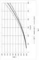
- Detailed mathematical analysis of droplet evaporation, including convective heat and mass transfer, radiative heat transfer and sulfuric acid thermodynamics show that the time for complete droplet evaporation depends on the temperature and the square of the initial droplet diameter.
- the time for complete evaporation can be as low as 0.2 seconds for a droplet with an initial diameter of 200 ⁇ m and as high as 2 seconds for a droplet with an initial diameter of 700 ⁇ m.
- the droplet size distribution from the sulfuric acid injection nozzle(s) is important.
- So-called pneumatic nozzles also known as air assisted or two-fluid nozzles
- These nozzles use kinetic energy to atomize the sulfuric acid into sufficiently small droplets and thus compressed air is mixed with the liquid at the nozzle tip.
- Low pressure steam, oxygen, N 2 and other gaseous fluids can be used instead of the air.
- Hydraulic atomization nozzles use the pressure of the liquid (i.e. sulfuric acid) to provide the energy for atomizing the liquid and by proper choice of pressure and nozzle design, these nozzles will also be able to produce small droplets. Generally, the droplet size decrease with increasing pressure, decreasing flow and increasing atomization angle. The benefit of the hydraulic nozzle is a lower operating cost as there is no consumption of compressed air. However, the capacity and turn-down ratio for these nozzles are not as good as for the air assisted nozzles.
- the characteristics of atomizing nozzles are usually measured with water as the liquid and air as the atomizing media (for air assisted nozzles only).
- the droplet size distribution is measured and characterized by one-dimensional parameters, such as VMD, SMD, DV 0.9 etc. The relevance of the characteristics depends on the application.
- the D 0.9 and D max values are the most relevant size characteristic parameters for the nozzle.
- the nozzles After some time in operation, the nozzles will eventually become worn, due to erosion by the acid and/or air (with particles) and due to corrosion by the sulfuric acid. Worn nozzles will produce less uniform spray patterns and the size distribution will shift towards larger droplets and therefore it is important to ensure that the nozzles are in good conditions, e.g. by visual inspections or by monitoring of liquid and, in the case of pneumatic nozzles, gas pressure drops over the nozzles. With proper design of the acid injection system, it will be furthermore be possible to isolate the acid injection lances and withdraw them from the reaction furnace while keeping the Claus plant in operation.
- One design choice is to provide a large reaction furnace chamber, such that the residence time of the process gas is high, but this may be costly.
- the turbulence in the reaction furnace chamber may be increased, by hindering or redirecting the flow, e.g. by using choke rings, vector walls, tangential inlets etc. which will provide a more narrow residence time distribution for the droplets, reducing the likelihood of a droplet experiencing a much lower than average residence time.
- a means of impaction such as an impaction wall, a checker wall or a packed volume or compartment of inert material
- a means of impaction can reduce the amount of large droplets, which, due to their high inertia, will not be able to follow the stream lines of the gas which is diverted close to the obstruction. Instead the large droplets willcontinue onwards and collide with the obstruction and evaporate from the obstruction surface.
- Such a means of impaction is typically quite robust and is not a supporting structure, to avoid stability problems due to the wear of the material of construction.
- a material catalytically active in conversion of SO 3 to SO 2 comprising e.g. one or more compounds of V, Mn, Fe, Co, Cu, Zn, Ni, Mo, W, Sb, Ti and Bi supported on one or more compounds of Al, Ti, Si, diatomaceous earth, Zr, Mg, and cordierite may also be positioned downstream the Claus reaction furnace.
- Such a material may be in the form of catalyst pellets or structured catalysts such as monoliths.
- H 2 SO 4 is an excellent O 2 carrier and has the (theoretical) potential to reduce the Claus tail gas volume flow by 67% compared to atmospheric air.
- the integrated process according to the present disclosure may also benefit from the use of oxygen enriched air or substantially pure oxygen in the Claus reaction furnace.
- oxygen enriched air has the benefit of reducing the amount of inert nitrogen in the process gas, and thus reducing the process gas volume and thus reduce plant size.
- the absence of dilution by nitrogen also has the effect of increasing the combustion temperature, which may be beneficial if impurities are present which need complete conversion, especially since the amount of oxygen in the Claus reaction furnace is sub-stoichiometic.
- the Claus catalyst is sensitive to presence of impurities, such as light hydrocarbons it may often be beneficial to operate the Claus reaction furnace with oxygen enriched air to achieve an elevated temperature for complete oxidation of impurities. This also has the further benefit of enabling an initial homogeneous non-catalytic Claus conversion, which may take place at temperatures above 900°C.
- the high combustion temperature may however be limited by the choices of construction materials in the Claus reaction furnace and downstream waste heat boiler.
- oxygen enrichment may increase the process gas temperature above the design temperatures for the materials.
- a combination of H 2 SO 4 recycle (which cools the process gas by evaporation and acid decomposition) will however make use of enriched O 2 in such a layout possible.
- the Claus tail gas combustor will typically be operated with atmospheric air, and in addition it may also be beneficial to direct gases with a low concentration of sulfur species to the Claus tail gas combustor as complete combustion of the sulfur species release considerably more energy than the partial oxidation taking place in the Claus reaction furnace.
- feedstock gases comprising high concentrations (e.g. more than 50vol%) of H 2 S to the Claus plant, while by-passing the less concentrated feedstock gases as well as feedstock gases comprising NH 3 to the Claus tail gas combustor.
- This support fuel may either be H 2 S, SWS gas or a hydrocarbon feed, but preferably an amount of an existing feedstock gas to the integrated Claus and sulfuric acid plant is used.
- the integration between the Claus process and the sulfuric acid process allows for integration benefits. These include the possibility to reduce the volumetric flow in the Claus process, by providing oxidant in the form of sulfuric acid, which can replace atmospheric air.
- the use of feedstock gas may be optimized such that feedstock gases comprising fuels contributing highly to sulfur production may be directed to the Claus process, whereas feedstock gases contributing with thermal energy and non-reacting products such as CO 2 may be directed to the sulfuric acid process.
- additional fuel may be required for providing the heat required for evaporation and dissociation of sulfuric acid.
- the integration of the two processes also enable a process where the operation of the Claus process is carried out with a low conversion such as 90% or 95% - since it may be cheaper to carry out the additional conversion in a sulfuric acid process compared to the addition of an extra Claus converter stage.
- an intermediate sulfuric acid storage tank may beneficially be located between the sulfuric acid outlet in the sulfuric acid plant and the sulfuric acid inlet to the Claus reaction furnace.
- Such a tank will allow for a more robust and safe control of the acid injection into the Claus reaction furnace, such that off-set periods can be operated without acid injection. For instance, during start-up and shut-down of the integrated process, it will be advantageous to operate without sulfuric acid injection. Also if the acid injection lances require service, the integrated process can be operated without shutting down the sulfuric acid process.
- the tank will also enable withdrawing sulfuric acid product, should this become a desired product and also allow import of sulfuric acid from other sources.
- the tank may also act as a buffer, decoupling operation of the Claus process from operation of the sulfuric acid process, which provides stability of the overall system
- a tank capacity for 1-4 days of sulfuric acid production is a good compromise between tank cost and flexibility of the integrated Claus process and sulfuric acid process.
- trip system for detecting and handling unexpected shut-downs (“trips") is common.
- trips For an integrated Claus process and sulfuric acid process, a trip may occur in either of the two processes, and it is important that the process is robust against such trips, such that the consequences are minimized.
- the sulfuric acid atomization lances and nozzles are cooled by the flow of atomization air and especially by the flow of the sulfuric acid.
- the majority of the cooling disappears and the temperature of the lance will increase.
- the lance material will be able to withstand the operating temperature of the reaction furnace, but any acid trapped in the lance will become hot. Corrosion rates will increase significantly and boiling of the sulfuric acid may take place too.
- the acid lines may be flushed with a gaseous flushing media to remove liquid acid from the lances, such that acid corrosion will be minimized while the lance will be provided with some extra cooling and ingress of Claus reaction furnace process gas into the lance is avoided.
- the flushing will continue as long as the acid flow is stopped.
- the flushing media will typically be a stream of N 2 which is already available and used in Claus plants and is an inert gas that will not interfere with the chemistry in the reaction furnace.
- air can be used as flushing media, but then also O 2 will be added to the Claus reaction furnace and there is a risk of interfering with the combustion air control if the flushing stream is not equipped with a flow instrument. Stop of sulfuric acid injection will also result in a temperature increase in the reaction furnace, but the temperature increase will in most circumstances not be problematic as the refractory walls will be able to withstand the higher temperature and a higher temperature will not have a bad impact of the Claus reaction furnace chemistry.
- the atomization media of pneumatic nozzles will continue flowing, such that the lance is cooled and process gas ingress to the lance is avoided.
- stagnant acid will remain in the acid line in the lance and without the cooling provided by the flow of acid, the acid temperature will increase and thus the corrosion rate of the acid will increase too.
- the acid line is flushed with N 2 or air to clean the line from acid. This flushing will be carried out for both pneumatic and hydraulic nozzles and will continue as long as desired to avoid ingress of process gas into the nozzles.
- sulfuric acid can also be produced in other sulfur abatement processes, and this sulfuric acid may also be directed to a Claus reaction furnace by similar principles, especially if the sulfuric acid produced is at least 90%.
- a standard Claus plant layout requires > 50 vol% H 2 S in the feed gas to be thermally self-sustainable in the Claus reaction furnace. With lower H 2 S concentrations, feed gas preheating and so-called split flow configuration is required. Claus plants treating feed gases with ⁇ 10-20 vol% H 2 S are rarely seen. Sulfuric acid processes, on the other hand, very efficiently treat these so-called lean H 2 S gases, producing concentrated sulfuric acid. The sulfuric acid product will be highly concentrated in sulfur and oxygen.
- a combination of a sulfuric acid plant to treat a lean H 2 S (and/or other sulfur compounds) gas in combination with a Claus plant treating a rich H 2 S gas and accepting the acid from the sulfuric acid plant will be a beneficial setup as the feed streams to both the Claus plant and sulfuric acid plant are optimal with regard to conversion efficiency, thermal efficiency and plant size/cost.
- the coupling between the Claus process and a sulfuric acid process may also be used to optimize the treating of feeds.
- Sulfuric acid processes and in particular the wet sulfuric acid process has the benefit of being well suited for contaminated feeds, including SWS gases comprising ammonia as discussed above, "dirty sulfur" comprising organic impurities and moderate amounts of inorganic impurities, dilute streams of H 2 S, SO 2 and other sulfur compounds, including flue gases from burners and FCC gas.
- rich H 2 S gases which must be diluted before being treated in a wet sulfuric acid plant, may instead be directed immediately for the Claus process.
- FIG. 1 a process for production of sulfur and sulfuric acid according to the prior art is shown.
- a feedstock gas 2 rich in H 2 S is directed to a Claus process, from which the tail gas 26 is directed to a sulfuric acid process.
- the feedstock gas 2 rich in H 2 S is directed to a Claus reaction furnace 66 converting an amount of the of H 2 S to SO 2 , to form a Claus converter feed gas 4 having a ratio between H 2 S and SO 2 close to 2:1.
- the Claus converter feed gas 4 is directed to a converter 8 containing a material catalytically active in the Claus reaction 12, providing a Claus process product 14.
- the Claus process product 14 is directed to a sulfur condensation unit 16, providing condensed sulfur 18 and a Claus tail gas 20.
- the wet Claus tail gas 20 is typically further reacted in the presence of additional material catalytically active in the Claus reaction followed by further condensation of sulfur, in one to four further Claus stages (not shown here), to provide a final wet Claus tail gas.
- An aqueous phase 24 may optionally be separated from the wet Claus tail gas 20 in a separator 22, providing a dried Claus tail gas 26, which is directed to a Claus tail gas combustor 32, providing a SO 2 converter feed gas 34.
- the SO 2 converter feed gas 34 is cooled and directed to an SO 2 converter 40, containing one or more beds(layers) of catalytically active material 42, 44, 46 optionally with interbed cooling, from which an SO 3 rich gas 48 is withdrawn.
- H 2 SO 4 is condensed as concentrated sulfuric acid 52 in a sulfuric acid condenser 50. From the sulfuric acid condenser 50 a substantially pure gas 62 may be withdrawn and directed to stack 64.
- fuel gas may be directed to the Claus tail gas combustor 32.
- Oxygen is also supplied, typically via air and preferably hot air from the sulfuric acid condenser (50), in order to supply oxygen for both the combustion reactions in Claus tail gas combustor 32 but also the oxygen required for the oxidation of SO 2 in the SO 2 converter.
- the oxygen for SO 2 oxidation can be added between the Claus tail gas combustor 32 outlet and the SO 2 converter 40 inlet.
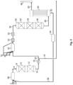
- FIG 2 an integrated Claus/sulfuric acid process with injection of sulfuric acid in the Claus reaction furnace 66 according to the present disclosure is shown.
- a feedstock gas 2 rich in H 2 S, sulfuric acid 56 and a gas rich in oxygen 72, as well as optionally a gas comprising a fuel and optionally, a second feedstock gas e.g. comprising a lower concentration of H 2 S and possibly NH 3 are directed to a Claus reaction furnace 66 and the combustion product is directed as an O 2 free Claus converter feed gas 4 to a converter 8.
- a waste heat boiler and optionally a sulfur condensation unit are typically installed to reduce the temperature to the optimal working temperature for the Claus catalyst, optionally also withdrawing elemental sulfur formed in the Claus reaction furnace 66.
- the O 2 free Claus converter feed gas 4 is directed to contact an optional material catalytically active in conversion of SO 3 to SO 2 10 (comprising e.g. one or more compounds of V, Mn, Fe, Co, Cu, Zn, Ni, Mo, W, Sb, Ti and Bi supported on one or more compounds of Al, Ti, Si, diatomaceous earth, Zr, Mg, and cordierite) and a material catalytically active in the Claus reaction 12, comprising e.g.
- the Claus process product 14 is directed to a sulfur condensation unit 16, providing condensed sulfur 18 and a Claus tail gas 20.
- the Claus tail gas 20 may optionally be further reacted in the presence of additional material catalytically active in the Claus process followed by further condensation of sulfur, in one to four further Claus stages (not shown here), to provide a final Claus tail gas.
- the final Claus tail gas comprising H 2 S 20 is directed to a Claus tail gas combustor 32, providing an SO 2 converter feed gas 34.
- an O 2 rich gas 72 is directed to the Claus tail gas combustor 32.
- the SO 2 converter feed gas 34 is typically cooled in a waste heat boiler (not shown) to provide optimal temperature for the first catalyst layer 42 in the SO 2 converter 40.
- the SO 2 converter feed gas 34 is directed to an SO 2 converter 40, containing one or more beds/layers of catalytically active material 42, 44, 46 optionally with interbed cooling, from which an SO 3 rich gas 48 is withdrawn.
- the SO 3 rich gas contains water, the SO 3 may hydrate to form H 2 SO 4 .
- H 2 SO 4 is condensed as concentrated sulfuric acid 52 in a sulfuric acid condenser 50. If the amount of water is insufficient for full hydration of SO 3 , addition of steam in a position upstream the sulfuric acid condenser 50 may be preferred.
- a substantially pure gas 62 may be withdrawn and directed to stack 64.
- all sulfuric acid 56 is recycled to the Claus reaction furnace 66, but optionally an amount of sulfuric acid may be withdrawn for other process purposes.
- an intermediate sulfuric acid tank (54) can be located between the sulfuric acid outlet of the sulfuric acid condenser 50 and the Claus reaction furnace 66, which may act as a buffer, decoupling operation of the Claus process from operation of the sulfuric acid process, which provides stability of the overall system.
- An optional catalytic reactor 35 for oxidation of remaining impurities such as hydrocarbons, CO, COS, CS 2 , S, H 2 and H 2 S is also shown in Fig.2 .
- the entire amount of second feedstock containing NH 3 and H 2 S 70 is directed to the Claus tail gas combustor 32, eliminating the risk of NH 3 -salt formation in the Claus condensers 16.
- a system for reduction of NOx 33 located between the Claus tail gas combustor 32 outlet and the inlet of the SO 2 converter 40 will be installed.
- a so-called SCR (Selective Catalytic Reaction) catalytic reactor will be used, requiring addition of NH 3 for the SCR reaction to proceed.
- the NH 3 addition can be from an external source or could be a small stream of the second feedstock containing NH 3 and H 2 S 70, which is then bypassed the Claus tail gas combustor.
- the conversion and condensation of sulfuric acid may be made in two stages, where remaining SO 2 from the first stage is further oxidized, hydrated and condensed, with the associated benefit of providing increased sulfur removal.
- additional SO 2 conversion can be achieved by installing a tail gas cleaning plant downstream the sulfuric acid process.
- a tail gas cleaning plant downstream the sulfuric acid process.
- alkaline scrubbers optionally combined with mist filters are the most common type.
- Scrubbers using H 2 O 2 or NH 3 are preferred as the effluent from these scrubbers is H 2 SO 4 and (NH 4 ) 2 SO 4 respectively, both of which can be recycled to the Claus reaction furnace for thermal destruction, i.e. eliminating a waste stream.
- the SO 2 converter feed gas 34 may be dried, such that the SO 3 rich gas 48 will contain little or no water.
- the condenser 50 may be replaced with an absorber, in which SO 3 may be absorbed in sulfuric acid, to provide concentrated sulfuric acid, by a dry sulfuric acid process.
- an amount of elemental sulfur may also be transferred to the Claus tail gas combustor 32, which will have the effect of providing SO 2 to the sulfuric acid process without introduction of water, which may be beneficial if it is desired to increase the SO 3 concentration, which may be beneficial in a dry sulfuric acid process.
- an amount of fuel gas 68 is directed to the Claus tail gas combustor 32 to ensure sufficiently high temperature for complete oxidation of all reduced compounds in the Claus tail gas 20.
- an amount of the feedstock gas 2 rich in H 2 S may also be split in an amount directed for the combustor of the Claus process 66 and an amount directed to the Claus tail gas combustor 32. This will reduce the need for fuel gas addition to the Claus tail gas combustor 32.
- a part of the Claus tail gas 20 is bypassed the Claus tail gas combustor 32 and combined with the hot off gas 34 from the Claus tail gas combustor in a gas mixing point just downstream the Claus tail gas combustor.
- the combined Claus tail gas combustor off gas and bypassed Claus tail gas must have a mixed gas temperature in excess of 400 °C to ensure homogeneous (i.e. gas phase) oxidation of H 2 S.
- an optional oxidation catalyst 35 can be installed between the gas mixing point and inlet to the SO 2 converter 40.
- a waste heat boiler or any other heat exchanger can be installed between the gas mixing point and inlet to the oxidation catalyst.
- the oxidation catalyst typically comprises a noble metal such as Pt or Pd.
- the gas comprising oxygen 72 may be pure oxygen or atmospheric air enriched in oxygen, such that it comprises less than 50%, 20%, 10% or even 1% N 2 +Ar.
- the atomization nozzle is assumed to be of the air assisted type, the initial droplet velocity is around 50 m/sec and the process gas flow velocity is around 10 m/sec.
- the initial droplet size is of relevance for the safe and long term operation of the Claus plant, especially if the residence time in the reaction furnace must be fixed at a value of 1-2 seconds. For 1 second residence time, droplets with initial diameters above 500 ⁇ m will not evaporate completely at 1,000 °C. As seen, there is a temperature effect too, however the influence of the initial droplet diameter is much stronger.
- the atomization of the sulfuric acid requires careful choice of nozzle type and operation of the nozzle. Numerous nozzles with their own characteristics regarding liquid capacity, pressure, type etc. exist in the market, ranging from very fine sprays with low capacity to coarse sprays with very large capacity, depending on the application.
- a small droplet size distribution is desired and for that purpose pneumatic nozzles (air-assisted, two phase) and hydraulic (pressure) nozzles are preferred, the former producing smaller droplets but with the "cost" of consumption of an atomization fluid, which is usually compressed air.
- the D 0.9 value has been calculated and is shown in table 1.
- the D 0.9 defines the diameter, where 90% of the total mass (or volume) of the droplets have smaller diameters.
- the data are based on water as the liquid and air, in the case of pneumatic nozzles, at room temperature.
- the pneumatic nozzle produces the smallest droplets.
- the hydraulic nozzle also produces fine droplets, but with sizes up to 500 ⁇ m.
- Nozzle #2 and #3 only differ by the pressure of the liquid and it is seen that higher liquid pressure leads to smaller droplets.
- the hydraulic nozzles may be an inferior choice if only 1 second residence time in the reaction furnace is allowed, but for 2 second residence time, the nozzles will work fine. See figure 3 for evaporation time of sulfuric acid droplets.
- Table 1 D 0.9 diameters (mass/volume based) for pneumatic and hydraulic nozzles. Data taken from table 18-18 and 18-19 in Perry's chemical engineers handbook, 4 th edition. Nozzle #1 Nozzle #2 Nozzle #3 Nozzle type Pneumatic Hydraulic Hydraulic Pressure of liquid/air 0.3 barg 6.9 barg 13.8 barg D 0.9 (mass/volume based) 55 ⁇ m 550 ⁇ m 420 ⁇ m
- Feed stock gas rich in H 2 S (stream 2 in figure 1 and 2 ): Total gas flow : 8190 Nm 3 /h H 2 S concentration : 94 vol% H 2 O concentration : 6 vol%
- the rich H 2 S gas is typical for refineries, and will also contain varying amounts of light hydrocarbons.
- Feed stock gas rich in H 2 S and NH 3 (stream 70 in figure 1 and 2 ): Total gas flow : 3669 Nm 3 /h H 2 S concentration : 28 vol% NH 3 concentration : 45 vol% H 2 O concentration : 27 vol%
- These streams comprising H 2 S and NH 3 are typically waste gases from so-called sour water strippers and recognized as SWS-gases. They may also contain varying amounts of light hydrocarbons.
- the fuel gas is a light hydrocarbon mixture (primarily CH 4 ), with a lower heating value of 12,200 kcal/Nm3.
- Feed streams, combustion air and Claus tail gas are preheated to the extent possible by utilizing heat evolved in the combined Claus+ sulfuric acid process.
- the Claus process operates with 94-95 % recovery of sulfur from the feed, i.e. can be a well operated Claus plant with only 2 catalytic stages.
- all feed streams are treated in the Claus process, providing a stream of 11.7 t/h elemental sulfur and a Claus tail gas comprising ⁇ 5% of the S in the feed gases.
- the sulfur species present in the Claus tail gas are oxidized and fuel gas is provided to maintain a combustor temperature of 1,000 °C, such that all reduced species, such as CO, COS, H 2 , H 2 S, Sx and CS 2 , are fully oxidized to CO 2 , H 2 O and SO 2 .
- concentration sulfuric acid is 2.4 t/h, calculated as 100 %w/w H 2 SO 4 .
- the total sulfur and sulfuric acid recovery is >99.9 % of the S in the feed, in compliance with even strict environmental legislation.
- H 2 SO 4 is not desired as a product and the entire acid production from the sulfuric acid process is recycled to the Claus reaction furnace.
- the amount of H 2 SO 4 recycle corresponds to ⁇ 6 % of the total S in the feed streams.
- the total elemental sulfur product flow is now equal to the S in the feed streams, corresponding to 107 % of the base case as described in example 3.
- the temperature in the Claus reaction furnace decreases by ⁇ 200 °C due to the evaporation and decomposition of the H 2 SO 4 , but the temperature is still well above the minimum for complete burnout of hydrocarbons and NH 3 . No fuel gas is needed in the Claus reaction furnace.
- fuel gas consumption in the Claus tail gas combustor has been minimized by bypassing a fraction of the SWS gas to the Claus tail gas combustor.
- the SWS gas has a high heating value and can easily act as a fuel gas.
- the concentrated H 2 S feed gas could also have been used, but since the SWS gas can be problematic in the Claus process and is unproblematic in the wet sulfuric acid process, the bypassing of SWS gas has greater benefits than bypassing the H 2 S gas.
- Process gas wise there will also be a reduction in gas volume as the NH3 in the SWS gas will increase the process gas volume in the Claus process due to the oxygen (air) requirements for combustion of NH 3 to N 2 and H 2 O.
- the amount of SWS gas recycled is adjusted such that 1,000 °C is achieved in the Claus tail gas combustor, ensuring complete burnout of reduced species from the Claus tail gas, such as H 2 S, COS, CO, H 2 , Sx and CS 2 .
- the process gas volume is reduced to 65 % of the base case, still with 107% elemental sulfur production.
- This process gas volume reduction can be either used for capacity boosting of an existing plant or significant cost reduction of a new plant.
- This example focus on the complete elimination of the SWS gas to the Claus plant, ensuring that ammonia salt formation in the sulfur condensers is impossible and thus decreases the risk of failure of the Claus plant.
- the process gas flow out of the Claus reaction furnace is 69 % of the base case, but a little higher compared to example 5 where only a fraction of the SWS gas is bypassed.
- the increase in process gas flow is due to requirement of fuel gas addition to the Claus reaction furnace to maintain the high operating temperature.
- the H 2 SO 4 production in the wet sulfuric acid plant has now increased to 17% of the S in the feed gases, recycling of the entire production now quenches the Claus reaction furnace temperature to an extent where fuel gas is required.
- the process gas from the Claus tail gas combustor has increased to 107 % of the base case, due to the increased sulfur feed to the sulfuric acid plant.
- this example seems less optimal than example 5, i.e. there is an optimum of H 2 SO 4 recycle ratio which depends on the actual feed gas flows and compositions. Bypassing even more feed stock gas will result in an increased sulfuric acid production, which will quench the Claus reaction furnace even more which again will require more fuel gas and therefore the Claus tail gas flow will increase.
- the optimal feed stock gas bypass is close to the point where the Claus reaction furnace operates at the minimum allowable temperature, i.e. the feed stock can be bypassed to produce more sulfuric acid until the Claus reaction furnace temperature reaches the limit for thermal destruction of hydrocarbons and sulfuric acid.
- Increasing the feed stock bypass ratio will reduce the fuel gas need in the Claus tail gas combustor, but will increase the fuel gas consumption in the Claus reaction furnace by a much larger ratio as the fuel gas in the Claus reaction furnace need to evaporate and decompose the sulfuric acid and heat up the process gas, whereas in the Claus tail gas combustor only heating up of process gas is required.
- the optimal H 2 SO 4 recycle flow is ⁇ 7 % of the S feed in the feed stream.
- the acid gas bypass to the Claus tail gas combustor is only 2 % as the relatively low H 2 S concentration result in a low temperature in the Claus reaction furnace and thus the sulfuric acid will quickly reduce the temperature and require fuel gas addition in the Claus reaction furnace.
- Using O 2 enriched air in the Claus reaction furnace will allow for a higher H 2 SO 4 recycle flow.
- an enriched air with 80 vol% O 2 is used as in the Claus process, whereas atmospheric air is used in the sulfuric acid process.
- the effect of the enriched air is a significantly reduced process gas flow out of the Claus reaction furnace, mainly due to the reduced amount of N 2 associated with the O 2 flow. Also the lower process gas flow enables operation of the Claus reaction furnace without fuel addition, as less inert gas has to be heated.
- the Claus tail gas feed to the Claus tail gas combustor is also significantly decreased.
- the process gas out of the Claus tail gas combustor is only 56% of the base case, it is relatively higher than the Claus plant flow due to the large amount of SWS gas bypass to the wet sulfuric acid plant.
Landscapes
- Chemical & Material Sciences (AREA)
- Organic Chemistry (AREA)
- Engineering & Computer Science (AREA)
- Chemical Kinetics & Catalysis (AREA)
- Inorganic Chemistry (AREA)
- Environmental & Geological Engineering (AREA)
- Oil, Petroleum & Natural Gas (AREA)
- General Chemical & Material Sciences (AREA)
- Analytical Chemistry (AREA)
- Biomedical Technology (AREA)
- Health & Medical Sciences (AREA)
- General Engineering & Computer Science (AREA)
- Mechanical Engineering (AREA)
- Automation & Control Theory (AREA)
- Combustion & Propulsion (AREA)
- Exhaust Gas Treatment By Means Of Catalyst (AREA)
- Treating Waste Gases (AREA)
- Catalysts (AREA)
- Organic Low-Molecular-Weight Compounds And Preparation Thereof (AREA)
- Solid-Sorbent Or Filter-Aiding Compositions (AREA)
Claims (12)
- Verfahren zur Herstellung von Schwefel aus einem Einsatzmaterial-Gas umfassend 15 %, 20 %, 30 Vol.-%, 40 Vol.-% oder 50 % bis 99 Vol.-% oder 100 Vol.-% H2S und einem Strom von Schwefelsäure, umfassend die Schrittea. Bereitstellen eines Einsatzstroms für einen Claus-Reaktionsofen, der das Einsatzmaterial-Gas, eine Menge an Schwefelsäure, eine Menge an Sauerstoff und gegebenenfalls eine Menge an Brennstoff umfasst, wobei die Menge an Sauerstoff unterstöchiometrisch ist,b. Leiten des Einsatzstroms für den Claus-Reaktionsofen zu einem Claus-Reaktionsofen, der bei erhöhter Temperatur, wie über 900°C, arbeitet, wobei ein Einsatzgas für einen Claus-Konverter bereitgestellt wird,c. Kühlen des Einsatzgases für den Claus-Konverter, um ein gekühltes Einsatzgas für den Claus-Konverter bereitzustellen, und gegebenenfalls Abziehen von elementarem Schwefel aus dem Gas,d. Leiten des gekühlten Einsatzgases für den Claus-Konverter nach optionaler Wiederaufheizung zur Kontaktierung mit einem in der Claus-Reaktion katalytisch aktiven Material,e. Abziehen eines Claus-Endgases und von elementarem Schwefel, gegebenenfalls durch Kühlen des Abstroms aus dem in der Claus-Reaktion katalytisch aktiven Material,f. Leiten eines Stroms umfassend das Claus-Endgas zu einer Behandlung des Claus-Endgases,gekennzeichnet, dadurch dass die Schwefelsäure, die zu dem Claus-Reaktionsofen geleitet wird, in Form von Tröpfchen mit einer Tröpfchengrößenverteilung vorliegt, die durch gekennzeichnet ist, dadurch dass 90 % der Masse der Tröpfchen einen Durchmesser unter 500 µm, 200 µm oder 100 µm haben.
- Verfahren nach Anspruch 1, wobei mindestens eine Menge an der Schwefelsäure über mindestens eine pneumatische Düse, die Schwefelsäure und ein Zerstäubungsmedium aufnimmt, in den Claus-Reaktionsofen geleitet wird.
- Verfahren nach Anspruch 2, bei dem das Zerstäubungsmedium komprimierte Luft ist und der Durchfluss 25 Nm3 Luft/Tonne Säure oder 50 Nm3 Luft/Tonne Säure bis 200 Nm3 Luft/Tonne Säure oder 500 Nm3 Luft/Tonne Säure beträgt.
- Verfahren nach Anspruch 1, wobei mindestens eine Menge an der Schwefelsäure über mindestens eine hydraulische Düse in den Claus-Reaktionsofen geleitet wird.
- Verfahren nach Anspruch 1, 2, 3 oder 4, wobei die durchschnittliche Verweilzeit des Prozessgases im Claus-Reaktionsofen weniger als 5 Sekunden, vorzugsweise weniger als 2 Sekunden, beträgt.
- Verfahren nach Anspruch 1, 2, 3, 4 oder 5, wobei der Claus-Reaktionsofen einen Turbulenzverstärker umfasst.
- Verfahren nach Anspruch 1, 2, 3, 4, 5 oder 6, wobei der Claus-Reaktionsofen ein Mittel zur Impaktion umfasst.
- Verfahren nach Anspruch 1, 2, 3, 4, 5, 6 oder 7, wobei die Behandlung des Claus-Endgases die Schritte umfasstg. Leiten eines Stroms umfassend das Claus-Endgas, Sauerstoff und einen Brennstoff als Einsatzmaterial-Gas zu einem Verbrenner für Claus-Endgas, der bei einer Temperatur von über 900 °C arbeitet, oder zu einem katalytischen Mittel zur Oxidation, wobei ein Einsatzgas für einen SO2-Konverter bereitgestellt wird,h. Leiten des Einsatzgases für den SO2-Konverter- zur Kontaktierung mit einem Material, das bei der Oxidation von SO2 zu SO3 katalytisch aktiv ist, wobei ein SOs-reiches Gas bereitgestellt wird,i. Umwandeln des SOs-reichen Gases in konzentrierte Schwefelsäure, entweder durch Absorption von SO3 in Schwefelsäure oder durch Hydratation von SO3, Kühlung und Kondensation von Schwefelsäure,j. Rückführen mindestens eines Teils der erzeugten Schwefelsäure in den Claus-Reaktionsofen.
- Verfahren nach Anspruch 1, 2, 3, 4, 5, 6, 7 oder 8, bei dem eine Menge an Schwefelsäure aus einer anderen Quelle als einer Behandlung von Claus-Endgas stammt
- Verfahren nach Anspruch 1, 2, 3, 4, 5, 6, 7, 8 oder 9, bei dem die Menge an Schwefel in dem Schwefelsäurestrom mehr als 1 %, 3 % oder 5 % und weniger als 17 %, 21 % oder 25 % der Gesamtmenge des aus dem Verfahren abgezogenen elementaren Schwefels beträgt.
- Prozessanlage umfassend einen Claus-Reaktionsofen, einen Claus-Abhitzekessel, einen Claus-Konvertierungs-Abschnitt, einen Verbrenner für Claus-Endgas und einen Schwefelsäureabschnitt, wobei der Claus-Reaktionsofen einen Ofen-Einlass, einen Düseneinlass für Säure und einen Auslass aufweist, der Claus-Abhitzekessel einen Gaseinlass, einen Gasauslass und einen Auslass für elementaren Schwefel aufweist, der Claus-Konvertierungs-Abschnitt einen Gaseinlass, einen Gasauslass und einen Auslass für elementaren Schwefel aufweist, der Verbrenner für Claus-Endgas einen Einlass und einen Auslass aufweist und der Schwefelsäureabschnitt einen Gaseinlass, einen Gasauslass und einen Auslass für Schwefelsäure aufweist, und wobei der Einlass des Claus-Reaktionsofens für die Aufnahme eines Einsatzmaterial-Gases und eines Oxidationsmittels konfiguriert ist, und der Auslass des Claus-Reaktionsofens so konfiguriert ist, dass er in fluider Verbindung mit dem Einlass des Claus-Abhitzekessels steht, wobei der Auslass des Claus-Abhitzekessels so konfiguriert ist, dass er in fluider Verbindung mit dem Einlass des Claus-Kovertierungs-Abschnitts steht, und wobei der Einlass des Verbrenners für Claus-Endgas so konfiguriert ist, dass er in fluider Verbindung mit dem Auslass des Gasauslasses des Claus-Konvertierungs-Abschnitts steht, der Auslass des Verbrenners für Claus-Endgas so konfiguriert ist, dass er in fluider Verbindung mit dem Einlass des Schwefelsäureabschnitts steht, ferner gekennzeichnet dadurch, dass der Auslass für Schwefelsäure des Schwefelsäureabschnitts in fluider Verbindung mit dem Düseneinlass für Säure des Claus-Reaktionsofens steht.
- Prozessanlage nach Anspruch 11, ferner umfassend einen Schwefelspeichertank mit einem Volumen, das der Menge an Schwefelsäure entspricht, die aus dem Auslass für Schwefelsäure des Schwefelsäureabschnitts in 1 Tag bis 4 Tagen abgezogen wird.
Applications Claiming Priority (5)
| Application Number | Priority Date | Filing Date | Title |
|---|---|---|---|
| DKPA201900543 | 2019-05-03 | ||
| DKPA201900655 | 2019-05-28 | ||
| DKPA201900681 | 2019-06-04 | ||
| DKPA201900687 | 2019-06-05 | ||
| PCT/EP2020/061934 WO2020225060A1 (en) | 2019-05-03 | 2020-04-30 | Method for production of sulfur and sulfuric acid |
Publications (2)
| Publication Number | Publication Date |
|---|---|
| EP3962857A1 EP3962857A1 (de) | 2022-03-09 |
| EP3962857B1 true EP3962857B1 (de) | 2023-06-07 |
Family
ID=70482641
Family Applications (4)
| Application Number | Title | Priority Date | Filing Date |
|---|---|---|---|
| EP20723345.3A Active EP3962858B1 (de) | 2019-05-03 | 2020-04-29 | Verfahren zur herstellung von elementarem schwefel durch teilweise oder vollständig katalytische oxidation von claus-restgas |
| EP20723346.1A Active EP3962859B1 (de) | 2019-05-03 | 2020-04-29 | Nachrüstung einer claus-anlage mit einem schwefelsäureplan |
| EP20723821.3A Active EP3963260B1 (de) | 2019-05-03 | 2020-04-29 | Verfahren zur herstellung von elementarem schwefel und schwefelsäure |
| EP20720326.6A Active EP3962857B1 (de) | 2019-05-03 | 2020-04-30 | Verfahren zur herstellung von schwefel und schwefelsäure |
Family Applications Before (3)
| Application Number | Title | Priority Date | Filing Date |
|---|---|---|---|
| EP20723345.3A Active EP3962858B1 (de) | 2019-05-03 | 2020-04-29 | Verfahren zur herstellung von elementarem schwefel durch teilweise oder vollständig katalytische oxidation von claus-restgas |
| EP20723346.1A Active EP3962859B1 (de) | 2019-05-03 | 2020-04-29 | Nachrüstung einer claus-anlage mit einem schwefelsäureplan |
| EP20723821.3A Active EP3963260B1 (de) | 2019-05-03 | 2020-04-29 | Verfahren zur herstellung von elementarem schwefel und schwefelsäure |
Country Status (8)
| Country | Link |
|---|---|
| US (4) | US12545580B2 (de) |
| EP (4) | EP3962858B1 (de) |
| CN (6) | CN113795710B (de) |
| ES (4) | ES2952273T3 (de) |
| MY (2) | MY205766A (de) |
| PL (4) | PL3963260T3 (de) |
| TW (1) | TW202108229A (de) |
| WO (4) | WO2020225061A1 (de) |
Families Citing this family (19)
| Publication number | Priority date | Publication date | Assignee | Title |
|---|---|---|---|---|
| EP3962858B1 (de) * | 2019-05-03 | 2023-06-07 | Topsoe A/S | Verfahren zur herstellung von elementarem schwefel durch teilweise oder vollständig katalytische oxidation von claus-restgas |
| EP4000716A1 (de) * | 2020-11-20 | 2022-05-25 | Haldor Topsøe A/S | Verfahren zur entschwefelung eines prozessgases |
| CN112648599A (zh) * | 2020-11-27 | 2021-04-13 | 山西焦化股份有限公司 | 一种延长制硫炉废锅内部结构使用周期的方法 |
| KR102820067B1 (ko) * | 2021-03-26 | 2025-06-12 | 에스케이이노베이션 주식회사 | 피트 베이퍼 배관을 갖는 클라우스 버너 |
| US11548784B1 (en) | 2021-10-26 | 2023-01-10 | Saudi Arabian Oil Company | Treating sulfur dioxide containing stream by acid aqueous absorption |
| US12116326B2 (en) | 2021-11-22 | 2024-10-15 | Saudi Arabian Oil Company | Conversion of hydrogen sulfide and carbon dioxide into hydrocarbons using non-thermal plasma and a catalyst |
| CN114042366B (zh) * | 2021-11-25 | 2024-10-29 | 中冶南方都市环保工程技术股份有限公司 | 一种焦化脱硫废盐制备硫酸的尾气处理系统及处理方法 |
| US11926799B2 (en) | 2021-12-14 | 2024-03-12 | Saudi Arabian Oil Company | 2-iso-alkyl-2-(4-hydroxyphenyl)propane derivatives used as emulsion breakers for crude oil |
| US12179129B2 (en) | 2021-12-14 | 2024-12-31 | Saudi Arabian Oil Company | Synergetic solvent for crude oil emulsion breakers |
| US20230339753A1 (en) * | 2022-04-21 | 2023-10-26 | Mahin Rameshni | Integrated sulfur recovery and hydrogen production process |
| US12264066B2 (en) | 2022-04-25 | 2025-04-01 | Messer Industries Usa, Inc. | Process and apparatus for acid regeneration |
| US20240109772A1 (en) | 2022-09-16 | 2024-04-04 | Saudi Arabian Oil Company | Hydrogen Production by Sulfur Steam Reforming |
| JP2025529522A (ja) | 2022-09-16 | 2025-09-04 | サウジ アラビアン オイル カンパニー | 硫黄の部分酸化による水素と硫酸との同時製造 |
| US12415725B2 (en) | 2022-10-26 | 2025-09-16 | Saudi Arabian Oil Company | Adaptive control of BTX removal in sulfur recovery units |
| US12577103B2 (en) | 2023-04-20 | 2026-03-17 | Messer Industries Usa, Inc. | Process and redox furnace for acid regeneration |
| US20240351877A1 (en) * | 2023-04-20 | 2024-10-24 | Messer Industries Usa, Inc. | Process and Apparatus for Oxygen Injection in a Sulfur Furnace |
| US20240391771A1 (en) * | 2023-05-22 | 2024-11-28 | Saudi Arabian Oil Company | Sulfur Recovery Unit to Convert Hydrogen Sulfide to Elemental Sulfur |
| KR20260033094A (ko) * | 2023-08-29 | 2026-03-10 | 벡텔 에너지 테크놀로지스 앤 솔루션스, 아이엔씨. | 이슬점 이하 황 회수를 위한 시스템 및 방법 |
| WO2025140974A1 (en) * | 2023-12-28 | 2025-07-03 | Metso Metals Oy | Process and plant for producing sulfuric acid |
Family Cites Families (40)
| Publication number | Priority date | Publication date | Assignee | Title |
|---|---|---|---|---|
| US3617221A (en) * | 1969-11-12 | 1971-11-02 | Pan American Petroleum Corp | Procedure for cooling down sulfur plant for inspection |
| DE2430909A1 (de) | 1974-06-27 | 1976-01-08 | Adsorptionstech Lab | Verfahren zur reinigung von clausofen-abgasen |
| US4171347A (en) | 1975-08-18 | 1979-10-16 | Union Oil Company Of California | Catalytic incineration of hydrogen sulfide from gas streams |
| US4070424A (en) | 1976-09-21 | 1978-01-24 | Uop Inc. | Method and apparatus for conditioning flue gas with a mist of H2 SO4 |
| US4208192A (en) | 1978-10-27 | 1980-06-17 | Uop Inc. | Sonic spray of H2 SD4 in a swirling heated air stream |
| GB8318098D0 (en) | 1983-07-04 | 1983-08-03 | Shell Int Research | Oxidation of hydrogen sulphide to elemental sulphur |
| US4826670A (en) * | 1985-03-20 | 1989-05-02 | Air Products And Chemicals, Inc. | Oxygen enriched claus system with sulfuric acid injection |
| FR2658433B1 (fr) | 1990-02-19 | 1994-05-13 | Rhone Poulenc Chimie | Catalyseurs pour le traitement des effluents gazeux contenant des composes du soufre et procede de traitement de ces effluents. |
| GB9205877D0 (en) * | 1992-03-18 | 1992-04-29 | Boc Group Plc | Treatment of waste or other material |
| EP0633219A1 (de) * | 1993-07-06 | 1995-01-11 | Shell Internationale Researchmaatschappij B.V. | Verfahren zur Entfernung von Schwefelverbindungen aus einem Gasstrom |
| FR2734809B1 (fr) | 1995-05-30 | 1997-07-18 | Elf Aquitaine | Procede de desulfuration catalytique d'un gaz renfermant les composes h2s et so2 et eventuellement cos et/ou cs2, avec recuperation desdits composes sous la forme de soufre et catalyseur pour la mise en oeuvre dudit procede |
| ATE312797T1 (de) * | 1999-10-22 | 2005-12-15 | Mecs Inc | Verfahren zur gewinung von schwefel |
| CN100588608C (zh) * | 2007-04-30 | 2010-02-10 | 中国石油集团工程设计有限责任公司 | 改良低温克劳斯硫磺回收方法 |
| US7695701B2 (en) | 2008-03-07 | 2010-04-13 | Du Pont | Process for treating acid gas in staged furnaces with inter-stage heat recovery |
| CN101879451B (zh) * | 2009-05-07 | 2013-06-12 | 中国石油化工股份有限公司 | 低温克劳斯尾气加氢催化剂及其制备方法 |
| CN101618863A (zh) * | 2009-06-05 | 2010-01-06 | 中国石化集团南京设计院 | 含硫化氢的废气制硫酸的方法 |
| DE102010013279B3 (de) * | 2010-03-29 | 2011-07-28 | Uhde GmbH, 44141 | Verfahren und Vorrichtung zur Verarbeitung eines kohlendioxidreichen Sauergases in einem Claus-Prozess |
| CN102371108A (zh) * | 2010-08-20 | 2012-03-14 | 中国石油化工集团公司 | 含硫化氢酸性气富氧空气焚烧生产硫酸的方法 |
| WO2012089776A1 (en) | 2010-12-31 | 2012-07-05 | Shell Internationale Research Maatschappij B.V. | Process for removing sulphur-containing contaminants from a gas stream |
| CN102198365B (zh) | 2011-05-11 | 2013-07-24 | 北京丰汉工程咨询有限公司 | 一种酸性气的处理方法 |
| CN102320577A (zh) * | 2011-06-22 | 2012-01-18 | 西南石油大学 | 一种加氢直接氧化硫磺回收工艺 |
| CN103566730B (zh) * | 2012-08-06 | 2015-12-02 | 中国石油化工股份有限公司 | 处理硫磺回收装置停工过程中产生的除硫吹扫尾气的方法 |
| CN103626136A (zh) * | 2012-08-23 | 2014-03-12 | 中国石油化工股份有限公司 | 一种含硫化氢废气湿法制硫酸的方法 |
| CN102910593B (zh) * | 2012-10-30 | 2014-09-17 | 美景(北京)环保科技有限公司 | 酸性气废气处理系统及处理方法 |
| EP2878358A1 (de) | 2013-12-02 | 2015-06-03 | Haldor Topsoe A/S | Katalytische Oxidation eines Schwefelwasserstoff enthaltenden Gases |
| EP2878367A1 (de) | 2013-12-02 | 2015-06-03 | Haldor Topsøe A/S | Katalysator zur Oxidation von Schwefelverbindungen |
| CN103894047B (zh) * | 2014-03-14 | 2016-04-06 | 成都华西堂投资有限公司 | 烟气污染物控制一体化净化回收工艺 |
| EP2942323A1 (de) * | 2014-05-09 | 2015-11-11 | Haldor Topsøe A/S | Herstellung von Schwefelsäure aus Koksofengasentschwefelungsprodukt |
| WO2016198369A1 (en) | 2015-06-12 | 2016-12-15 | Haldor Topsøe A/S | Hydrogen sulfide abatement via removal of sulfur trioxide |
| US9624106B2 (en) | 2015-08-14 | 2017-04-18 | Mahin Rameshni | Supersulf-a process with internal cooling and heating reactors in subdewpoint sulfur recovery and tail gas treating systems |
| CN105692563B (zh) | 2016-01-27 | 2018-11-13 | 山东三维石化工程股份有限公司 | Swsr-7硫回收工艺及装置 |
| ITUA20164554A1 (it) * | 2016-06-21 | 2017-12-21 | Saipem Spa | Processo integrato per la produzione di acido solforico e zolfo |
| CN106219499B (zh) | 2016-07-15 | 2019-03-15 | 碧海舟(北京)节能环保装备有限公司 | 脱硫及硫回收工艺 |
| WO2018096178A1 (en) * | 2016-11-28 | 2018-05-31 | Haldor Topsøe A/S | Method for production of sulfur and sulfuric acid |
| US10106411B2 (en) | 2017-03-13 | 2018-10-23 | Saudi Arabian Oil Company | Enhancement of claus tail gas treatment by sulfur dioxide-selective membrane technology and sulfur dioxide-selective absorption technology |
| CN207468199U (zh) | 2017-06-20 | 2018-06-08 | 中国石油集团东北炼化工程有限公司葫芦岛设计院 | 用于硫磺回收与烷基化废酸联合处理清洁生产的装置 |
| CN107311117B (zh) | 2017-06-20 | 2024-01-12 | 中国石油集团东北炼化工程有限公司葫芦岛设计院 | 硫磺回收与烷基化废酸联合处理清洁生产工艺及装置 |
| CN108298505B (zh) * | 2018-01-29 | 2021-07-06 | 华陆工程科技有限责任公司 | 处理含h2s酸性气同时制取硫酸和硫磺的联合工艺 |
| CN108786441B (zh) * | 2018-05-31 | 2021-03-19 | 武汉钢铁有限公司 | 焦炉烟气电迁移脱硫制硫磺工艺 |
| EP3962858B1 (de) * | 2019-05-03 | 2023-06-07 | Topsoe A/S | Verfahren zur herstellung von elementarem schwefel durch teilweise oder vollständig katalytische oxidation von claus-restgas |
-
2020
- 2020-04-29 EP EP20723345.3A patent/EP3962858B1/de active Active
- 2020-04-29 ES ES20723345T patent/ES2952273T3/es active Active
- 2020-04-29 CN CN202080033308.XA patent/CN113795710B/zh active Active
- 2020-04-29 MY MYPI2021006342A patent/MY205766A/en unknown
- 2020-04-29 EP EP20723346.1A patent/EP3962859B1/de active Active
- 2020-04-29 US US17/606,642 patent/US12545580B2/en active Active
- 2020-04-29 PL PL20723821.3T patent/PL3963260T3/pl unknown
- 2020-04-29 CN CN202080032998.7A patent/CN113784914B/zh active Active
- 2020-04-29 WO PCT/EP2020/061937 patent/WO2020225061A1/en not_active Ceased
- 2020-04-29 PL PL20723346.1T patent/PL3962859T3/pl unknown
- 2020-04-29 MY MYPI2021006310A patent/MY208837A/en unknown
- 2020-04-29 US US17/606,607 patent/US11807527B2/en active Active
- 2020-04-29 US US17/606,557 patent/US11618677B2/en active Active
- 2020-04-29 PL PL20723345.3T patent/PL3962858T3/pl unknown
- 2020-04-29 WO PCT/EP2020/061939 patent/WO2020225062A1/en not_active Ceased
- 2020-04-29 ES ES20723821T patent/ES2949937T3/es active Active
- 2020-04-29 EP EP20723821.3A patent/EP3963260B1/de active Active
- 2020-04-29 ES ES20723346T patent/ES2951295T3/es active Active
- 2020-04-29 WO PCT/EP2020/061940 patent/WO2020225063A1/en not_active Ceased
- 2020-04-30 EP EP20720326.6A patent/EP3962857B1/de active Active
- 2020-04-30 ES ES20720326T patent/ES2952225T3/es active Active
- 2020-04-30 US US17/594,680 patent/US11691877B2/en active Active
- 2020-04-30 TW TW109114602A patent/TW202108229A/zh unknown
- 2020-04-30 PL PL20720326.6T patent/PL3962857T3/pl unknown
- 2020-04-30 WO PCT/EP2020/061934 patent/WO2020225060A1/en not_active Ceased
- 2020-05-06 CN CN202010372644.9A patent/CN111874872B/zh active Active
- 2020-05-06 CN CN202020721352.7U patent/CN212832845U/zh active Active
- 2020-05-06 CN CN202010372289.5A patent/CN111874871B/zh active Active
- 2020-05-06 CN CN202020721325.XU patent/CN213834549U/zh not_active Withdrawn - After Issue
Also Published As
Similar Documents
| Publication | Publication Date | Title |
|---|---|---|
| EP3962857B1 (de) | Verfahren zur herstellung von schwefel und schwefelsäure | |
| CA3083560C (en) | Method for production of sulfur involving recycle of sulfuric acid | |
| RU2822142C2 (ru) | Способ получения серы и серной кислоты | |
| TWI918602B (zh) | 製造硫和硫酸的方法 | |
| RU2827769C2 (ru) | Модернизация установки клауса сернокислотной установкой | |
| RU2824360C2 (ru) | Способ получения элементарной серы и серной кислоты | |
| DK201800928A1 (en) | Method for production of sulfur and sulfuric acid | |
| EA039970B1 (ru) | Способ получения серы и серной кислоты |
Legal Events
| Date | Code | Title | Description |
|---|---|---|---|
| STAA | Information on the status of an ep patent application or granted ep patent |
Free format text: STATUS: UNKNOWN |
|
| STAA | Information on the status of an ep patent application or granted ep patent |
Free format text: STATUS: THE INTERNATIONAL PUBLICATION HAS BEEN MADE |
|
| PUAI | Public reference made under article 153(3) epc to a published international application that has entered the european phase |
Free format text: ORIGINAL CODE: 0009012 |
|
| STAA | Information on the status of an ep patent application or granted ep patent |
Free format text: STATUS: REQUEST FOR EXAMINATION WAS MADE |
|
| 17P | Request for examination filed |
Effective date: 20211111 |
|
| AK | Designated contracting states |
Kind code of ref document: A1 Designated state(s): AL AT BE BG CH CY CZ DE DK EE ES FI FR GB GR HR HU IE IS IT LI LT LU LV MC MK MT NL NO PL PT RO RS SE SI SK SM TR |
|
| DAV | Request for validation of the european patent (deleted) | ||
| DAX | Request for extension of the european patent (deleted) | ||
| RAP3 | Party data changed (applicant data changed or rights of an application transferred) |
Owner name: TOPSOE A/S |
|
| GRAP | Despatch of communication of intention to grant a patent |
Free format text: ORIGINAL CODE: EPIDOSNIGR1 |
|
| STAA | Information on the status of an ep patent application or granted ep patent |
Free format text: STATUS: GRANT OF PATENT IS INTENDED |
|
| RIC1 | Information provided on ipc code assigned before grant |
Ipc: F23C 6/04 20060101ALI20221017BHEP Ipc: B01D 53/86 20060101ALI20221017BHEP Ipc: F23C 6/00 20060101ALI20221017BHEP Ipc: B01D 53/52 20060101ALI20221017BHEP Ipc: C01B 17/76 20060101ALI20221017BHEP Ipc: C01B 17/04 20060101AFI20221017BHEP |
|
| INTG | Intention to grant announced |
Effective date: 20221104 |
|
| GRAS | Grant fee paid |
Free format text: ORIGINAL CODE: EPIDOSNIGR3 |
|
| GRAA | (expected) grant |
Free format text: ORIGINAL CODE: 0009210 |
|
| STAA | Information on the status of an ep patent application or granted ep patent |
Free format text: STATUS: THE PATENT HAS BEEN GRANTED |
|
| AK | Designated contracting states |
Kind code of ref document: B1 Designated state(s): AL AT BE BG CH CY CZ DE DK EE ES FI FR GB GR HR HU IE IS IT LI LT LU LV MC MK MT NL NO PL PT RO RS SE SI SK SM TR |
|
| REG | Reference to a national code |
Ref country code: GB Ref legal event code: FG4D |
|
| REG | Reference to a national code |
Ref country code: CH Ref legal event code: EP Ref country code: AT Ref legal event code: REF Ref document number: 1574562 Country of ref document: AT Kind code of ref document: T Effective date: 20230615 Ref country code: DE Ref legal event code: R096 Ref document number: 602020012034 Country of ref document: DE |
|
| P01 | Opt-out of the competence of the unified patent court (upc) registered |
Effective date: 20230701 |
|
| REG | Reference to a national code |
Ref country code: LT Ref legal event code: MG9D |
|
| REG | Reference to a national code |
Ref country code: NL Ref legal event code: MP Effective date: 20230607 |
|
| REG | Reference to a national code |
Ref country code: ES Ref legal event code: FG2A Ref document number: 2952225 Country of ref document: ES Kind code of ref document: T3 Effective date: 20231030 |
|
| PG25 | Lapsed in a contracting state [announced via postgrant information from national office to epo] |
Ref country code: SE Free format text: LAPSE BECAUSE OF FAILURE TO SUBMIT A TRANSLATION OF THE DESCRIPTION OR TO PAY THE FEE WITHIN THE PRESCRIBED TIME-LIMIT Effective date: 20230607 Ref country code: NO Free format text: LAPSE BECAUSE OF FAILURE TO SUBMIT A TRANSLATION OF THE DESCRIPTION OR TO PAY THE FEE WITHIN THE PRESCRIBED TIME-LIMIT Effective date: 20230907 |
|
| REG | Reference to a national code |
Ref country code: AT Ref legal event code: MK05 Ref document number: 1574562 Country of ref document: AT Kind code of ref document: T Effective date: 20230607 |
|
| PG25 | Lapsed in a contracting state [announced via postgrant information from national office to epo] |
Ref country code: RS Free format text: LAPSE BECAUSE OF FAILURE TO SUBMIT A TRANSLATION OF THE DESCRIPTION OR TO PAY THE FEE WITHIN THE PRESCRIBED TIME-LIMIT Effective date: 20230607 Ref country code: NL Free format text: LAPSE BECAUSE OF FAILURE TO SUBMIT A TRANSLATION OF THE DESCRIPTION OR TO PAY THE FEE WITHIN THE PRESCRIBED TIME-LIMIT Effective date: 20230607 Ref country code: LV Free format text: LAPSE BECAUSE OF FAILURE TO SUBMIT A TRANSLATION OF THE DESCRIPTION OR TO PAY THE FEE WITHIN THE PRESCRIBED TIME-LIMIT Effective date: 20230607 Ref country code: LT Free format text: LAPSE BECAUSE OF FAILURE TO SUBMIT A TRANSLATION OF THE DESCRIPTION OR TO PAY THE FEE WITHIN THE PRESCRIBED TIME-LIMIT Effective date: 20230607 Ref country code: HR Free format text: LAPSE BECAUSE OF FAILURE TO SUBMIT A TRANSLATION OF THE DESCRIPTION OR TO PAY THE FEE WITHIN THE PRESCRIBED TIME-LIMIT Effective date: 20230607 Ref country code: GR Free format text: LAPSE BECAUSE OF FAILURE TO SUBMIT A TRANSLATION OF THE DESCRIPTION OR TO PAY THE FEE WITHIN THE PRESCRIBED TIME-LIMIT Effective date: 20230908 |
|
| PG25 | Lapsed in a contracting state [announced via postgrant information from national office to epo] |
Ref country code: FI Free format text: LAPSE BECAUSE OF FAILURE TO SUBMIT A TRANSLATION OF THE DESCRIPTION OR TO PAY THE FEE WITHIN THE PRESCRIBED TIME-LIMIT Effective date: 20230607 |
|
| PG25 | Lapsed in a contracting state [announced via postgrant information from national office to epo] |
Ref country code: SK Free format text: LAPSE BECAUSE OF FAILURE TO SUBMIT A TRANSLATION OF THE DESCRIPTION OR TO PAY THE FEE WITHIN THE PRESCRIBED TIME-LIMIT Effective date: 20230607 |
|
| PG25 | Lapsed in a contracting state [announced via postgrant information from national office to epo] |
Ref country code: IS Free format text: LAPSE BECAUSE OF FAILURE TO SUBMIT A TRANSLATION OF THE DESCRIPTION OR TO PAY THE FEE WITHIN THE PRESCRIBED TIME-LIMIT Effective date: 20231007 |
|
| PG25 | Lapsed in a contracting state [announced via postgrant information from national office to epo] |
Ref country code: SM Free format text: LAPSE BECAUSE OF FAILURE TO SUBMIT A TRANSLATION OF THE DESCRIPTION OR TO PAY THE FEE WITHIN THE PRESCRIBED TIME-LIMIT Effective date: 20230607 Ref country code: SK Free format text: LAPSE BECAUSE OF FAILURE TO SUBMIT A TRANSLATION OF THE DESCRIPTION OR TO PAY THE FEE WITHIN THE PRESCRIBED TIME-LIMIT Effective date: 20230607 Ref country code: RO Free format text: LAPSE BECAUSE OF FAILURE TO SUBMIT A TRANSLATION OF THE DESCRIPTION OR TO PAY THE FEE WITHIN THE PRESCRIBED TIME-LIMIT Effective date: 20230607 Ref country code: PT Free format text: LAPSE BECAUSE OF FAILURE TO SUBMIT A TRANSLATION OF THE DESCRIPTION OR TO PAY THE FEE WITHIN THE PRESCRIBED TIME-LIMIT Effective date: 20231009 Ref country code: IS Free format text: LAPSE BECAUSE OF FAILURE TO SUBMIT A TRANSLATION OF THE DESCRIPTION OR TO PAY THE FEE WITHIN THE PRESCRIBED TIME-LIMIT Effective date: 20231007 Ref country code: EE Free format text: LAPSE BECAUSE OF FAILURE TO SUBMIT A TRANSLATION OF THE DESCRIPTION OR TO PAY THE FEE WITHIN THE PRESCRIBED TIME-LIMIT Effective date: 20230607 Ref country code: CZ Free format text: LAPSE BECAUSE OF FAILURE TO SUBMIT A TRANSLATION OF THE DESCRIPTION OR TO PAY THE FEE WITHIN THE PRESCRIBED TIME-LIMIT Effective date: 20230607 Ref country code: AT Free format text: LAPSE BECAUSE OF FAILURE TO SUBMIT A TRANSLATION OF THE DESCRIPTION OR TO PAY THE FEE WITHIN THE PRESCRIBED TIME-LIMIT Effective date: 20230607 |
|
| REG | Reference to a national code |
Ref country code: DE Ref legal event code: R097 Ref document number: 602020012034 Country of ref document: DE |
|
| PLBE | No opposition filed within time limit |
Free format text: ORIGINAL CODE: 0009261 |
|
| STAA | Information on the status of an ep patent application or granted ep patent |
Free format text: STATUS: NO OPPOSITION FILED WITHIN TIME LIMIT |
|
| PG25 | Lapsed in a contracting state [announced via postgrant information from national office to epo] |
Ref country code: DK Free format text: LAPSE BECAUSE OF FAILURE TO SUBMIT A TRANSLATION OF THE DESCRIPTION OR TO PAY THE FEE WITHIN THE PRESCRIBED TIME-LIMIT Effective date: 20230607 |
|
| PG25 | Lapsed in a contracting state [announced via postgrant information from national office to epo] |
Ref country code: SI Free format text: LAPSE BECAUSE OF FAILURE TO SUBMIT A TRANSLATION OF THE DESCRIPTION OR TO PAY THE FEE WITHIN THE PRESCRIBED TIME-LIMIT Effective date: 20230607 |
|
| 26N | No opposition filed |
Effective date: 20240308 |
|
| PG25 | Lapsed in a contracting state [announced via postgrant information from national office to epo] |
Ref country code: SI Free format text: LAPSE BECAUSE OF FAILURE TO SUBMIT A TRANSLATION OF THE DESCRIPTION OR TO PAY THE FEE WITHIN THE PRESCRIBED TIME-LIMIT Effective date: 20230607 |
|
| PG25 | Lapsed in a contracting state [announced via postgrant information from national office to epo] |
Ref country code: BG Free format text: LAPSE BECAUSE OF FAILURE TO SUBMIT A TRANSLATION OF THE DESCRIPTION OR TO PAY THE FEE WITHIN THE PRESCRIBED TIME-LIMIT Effective date: 20230607 |
|
| PG25 | Lapsed in a contracting state [announced via postgrant information from national office to epo] |
Ref country code: MC Free format text: LAPSE BECAUSE OF FAILURE TO SUBMIT A TRANSLATION OF THE DESCRIPTION OR TO PAY THE FEE WITHIN THE PRESCRIBED TIME-LIMIT Effective date: 20230607 |
|
| PG25 | Lapsed in a contracting state [announced via postgrant information from national office to epo] |
Ref country code: MC Free format text: LAPSE BECAUSE OF FAILURE TO SUBMIT A TRANSLATION OF THE DESCRIPTION OR TO PAY THE FEE WITHIN THE PRESCRIBED TIME-LIMIT Effective date: 20230607 Ref country code: BG Free format text: LAPSE BECAUSE OF FAILURE TO SUBMIT A TRANSLATION OF THE DESCRIPTION OR TO PAY THE FEE WITHIN THE PRESCRIBED TIME-LIMIT Effective date: 20230607 |
|
| REG | Reference to a national code |
Ref country code: CH Ref legal event code: PL |
|
| PG25 | Lapsed in a contracting state [announced via postgrant information from national office to epo] |
Ref country code: LU Free format text: LAPSE BECAUSE OF NON-PAYMENT OF DUE FEES Effective date: 20240430 |
|
| GBPC | Gb: european patent ceased through non-payment of renewal fee |
Effective date: 20240430 |
|
| REG | Reference to a national code |
Ref country code: BE Ref legal event code: MM Effective date: 20240430 |
|
| PG25 | Lapsed in a contracting state [announced via postgrant information from national office to epo] |
Ref country code: LU Free format text: LAPSE BECAUSE OF NON-PAYMENT OF DUE FEES Effective date: 20240430 |
|
| PG25 | Lapsed in a contracting state [announced via postgrant information from national office to epo] |
Ref country code: BE Free format text: LAPSE BECAUSE OF NON-PAYMENT OF DUE FEES Effective date: 20240430 |
|
| PG25 | Lapsed in a contracting state [announced via postgrant information from national office to epo] |
Ref country code: GB Free format text: LAPSE BECAUSE OF NON-PAYMENT OF DUE FEES Effective date: 20240430 |
|
| PG25 | Lapsed in a contracting state [announced via postgrant information from national office to epo] |
Ref country code: GB Free format text: LAPSE BECAUSE OF NON-PAYMENT OF DUE FEES Effective date: 20240430 Ref country code: BE Free format text: LAPSE BECAUSE OF NON-PAYMENT OF DUE FEES Effective date: 20240430 Ref country code: CH Free format text: LAPSE BECAUSE OF NON-PAYMENT OF DUE FEES Effective date: 20240430 |
|
| PG25 | Lapsed in a contracting state [announced via postgrant information from national office to epo] |
Ref country code: IE Free format text: LAPSE BECAUSE OF NON-PAYMENT OF DUE FEES Effective date: 20240430 |
|
| PGFP | Annual fee paid to national office [announced via postgrant information from national office to epo] |
Ref country code: DE Payment date: 20250428 Year of fee payment: 6 Ref country code: PL Payment date: 20250418 Year of fee payment: 6 |
|
| PGFP | Annual fee paid to national office [announced via postgrant information from national office to epo] |
Ref country code: ES Payment date: 20250513 Year of fee payment: 6 |
|
| PGFP | Annual fee paid to national office [announced via postgrant information from national office to epo] |
Ref country code: IT Payment date: 20250422 Year of fee payment: 6 |
|
| PGFP | Annual fee paid to national office [announced via postgrant information from national office to epo] |
Ref country code: FR Payment date: 20250424 Year of fee payment: 6 |
|
| PGFP | Annual fee paid to national office [announced via postgrant information from national office to epo] |
Ref country code: TR Payment date: 20250418 Year of fee payment: 6 |
|
| PG25 | Lapsed in a contracting state [announced via postgrant information from national office to epo] |
Ref country code: CY Free format text: LAPSE BECAUSE OF FAILURE TO SUBMIT A TRANSLATION OF THE DESCRIPTION OR TO PAY THE FEE WITHIN THE PRESCRIBED TIME-LIMIT; INVALID AB INITIO Effective date: 20200430 |
|
| PG25 | Lapsed in a contracting state [announced via postgrant information from national office to epo] |
Ref country code: HU Free format text: LAPSE BECAUSE OF FAILURE TO SUBMIT A TRANSLATION OF THE DESCRIPTION OR TO PAY THE FEE WITHIN THE PRESCRIBED TIME-LIMIT; INVALID AB INITIO Effective date: 20200430 |