EP3961201B1 - Sensor - Google Patents
Sensor Download PDFInfo
- Publication number
- EP3961201B1 EP3961201B1 EP19926223.9A EP19926223A EP3961201B1 EP 3961201 B1 EP3961201 B1 EP 3961201B1 EP 19926223 A EP19926223 A EP 19926223A EP 3961201 B1 EP3961201 B1 EP 3961201B1
- Authority
- EP
- European Patent Office
- Prior art keywords
- electrode
- detecting
- sensor
- electrodes
- unit
- Prior art date
- Legal status (The legal status is an assumption and is not a legal conclusion. Google has not performed a legal analysis and makes no representation as to the accuracy of the status listed.)
- Active
Links
Images


Classifications
-
- G—PHYSICS
- G01—MEASURING; TESTING
- G01N—INVESTIGATING OR ANALYSING MATERIALS BY DETERMINING THEIR CHEMICAL OR PHYSICAL PROPERTIES
- G01N15/00—Investigating characteristics of particles; Investigating permeability, pore-volume or surface-area of porous materials
- G01N15/06—Investigating concentration of particle suspensions
- G01N15/0606—Investigating concentration of particle suspensions by collecting particles on a support
-
- G—PHYSICS
- G01—MEASURING; TESTING
- G01N—INVESTIGATING OR ANALYSING MATERIALS BY DETERMINING THEIR CHEMICAL OR PHYSICAL PROPERTIES
- G01N27/00—Investigating or analysing materials by the use of electric, electrochemical, or magnetic means
- G01N27/02—Investigating or analysing materials by the use of electric, electrochemical, or magnetic means by investigating impedance
- G01N27/04—Investigating or analysing materials by the use of electric, electrochemical, or magnetic means by investigating impedance by investigating resistance
- G01N27/06—Investigating or analysing materials by the use of electric, electrochemical, or magnetic means by investigating impedance by investigating resistance of a liquid
- G01N27/07—Construction of measuring vessels; Electrodes therefor
-
- G—PHYSICS
- G01—MEASURING; TESTING
- G01N—INVESTIGATING OR ANALYSING MATERIALS BY DETERMINING THEIR CHEMICAL OR PHYSICAL PROPERTIES
- G01N27/00—Investigating or analysing materials by the use of electric, electrochemical, or magnetic means
- G01N27/02—Investigating or analysing materials by the use of electric, electrochemical, or magnetic means by investigating impedance
- G01N27/04—Investigating or analysing materials by the use of electric, electrochemical, or magnetic means by investigating impedance by investigating resistance
-
- G—PHYSICS
- G01—MEASURING; TESTING
- G01D—MEASURING NOT SPECIALLY ADAPTED FOR A SPECIFIC VARIABLE; ARRANGEMENTS FOR MEASURING TWO OR MORE VARIABLES NOT COVERED IN A SINGLE OTHER SUBCLASS; TARIFF METERING APPARATUS; MEASURING OR TESTING NOT OTHERWISE PROVIDED FOR
- G01D5/00—Mechanical means for transferring the output of a sensing member; Means for converting the output of a sensing member to another variable where the form or nature of the sensing member does not constrain the means for converting; Transducers not specially adapted for a specific variable
- G01D5/12—Mechanical means for transferring the output of a sensing member; Means for converting the output of a sensing member to another variable where the form or nature of the sensing member does not constrain the means for converting; Transducers not specially adapted for a specific variable using electric or magnetic means
- G01D5/14—Mechanical means for transferring the output of a sensing member; Means for converting the output of a sensing member to another variable where the form or nature of the sensing member does not constrain the means for converting; Transducers not specially adapted for a specific variable using electric or magnetic means influencing the magnitude of a current or voltage
- G01D5/16—Mechanical means for transferring the output of a sensing member; Means for converting the output of a sensing member to another variable where the form or nature of the sensing member does not constrain the means for converting; Transducers not specially adapted for a specific variable using electric or magnetic means influencing the magnitude of a current or voltage by varying resistance
-
- G—PHYSICS
- G01—MEASURING; TESTING
- G01N—INVESTIGATING OR ANALYSING MATERIALS BY DETERMINING THEIR CHEMICAL OR PHYSICAL PROPERTIES
- G01N15/00—Investigating characteristics of particles; Investigating permeability, pore-volume or surface-area of porous materials
- G01N15/06—Investigating concentration of particle suspensions
- G01N15/0656—Investigating concentration of particle suspensions using electric, e.g. electrostatic methods or magnetic methods
-
- G—PHYSICS
- G01—MEASURING; TESTING
- G01N—INVESTIGATING OR ANALYSING MATERIALS BY DETERMINING THEIR CHEMICAL OR PHYSICAL PROPERTIES
- G01N27/00—Investigating or analysing materials by the use of electric, electrochemical, or magnetic means
- G01N27/02—Investigating or analysing materials by the use of electric, electrochemical, or magnetic means by investigating impedance
- G01N27/04—Investigating or analysing materials by the use of electric, electrochemical, or magnetic means by investigating impedance by investigating resistance
- G01N27/12—Investigating or analysing materials by the use of electric, electrochemical, or magnetic means by investigating impedance by investigating resistance of a solid body in dependence upon absorption of a fluid; of a solid body in dependence upon reaction with a fluid, for detecting components in the fluid
-
- G—PHYSICS
- G01—MEASURING; TESTING
- G01N—INVESTIGATING OR ANALYSING MATERIALS BY DETERMINING THEIR CHEMICAL OR PHYSICAL PROPERTIES
- G01N33/00—Investigating or analysing materials by specific methods not covered by groups G01N1/00 - G01N31/00
- G01N33/26—Oils; Viscous liquids; Paints; Inks
- G01N33/28—Oils, i.e. hydrocarbon liquids
- G01N33/2835—Specific substances contained in the oils or fuels
-
- G—PHYSICS
- G01—MEASURING; TESTING
- G01N—INVESTIGATING OR ANALYSING MATERIALS BY DETERMINING THEIR CHEMICAL OR PHYSICAL PROPERTIES
- G01N33/00—Investigating or analysing materials by specific methods not covered by groups G01N1/00 - G01N31/00
- G01N33/26—Oils; Viscous liquids; Paints; Inks
- G01N33/28—Oils, i.e. hydrocarbon liquids
- G01N33/2835—Specific substances contained in the oils or fuels
- G01N33/2858—Metal particles
-
- G—PHYSICS
- G01—MEASURING; TESTING
- G01N—INVESTIGATING OR ANALYSING MATERIALS BY DETERMINING THEIR CHEMICAL OR PHYSICAL PROPERTIES
- G01N15/00—Investigating characteristics of particles; Investigating permeability, pore-volume or surface-area of porous materials
- G01N2015/0042—Investigating dispersion of solids
- G01N2015/0053—Investigating dispersion of solids in liquids, e.g. trouble
Definitions
- the present invention relates to a sensor.
- a mechanical device such as a speed reducer is housed in a housing filled with a lubricant oil in order to prevent the mechanical parts such as gears from being damaged. If the mechanical parts are worn out during operation of the mechanical device, abrasion powder is mixed into the lubricant oil.
- the abrasion powder is, for example, a conductive substance such as iron powder.
- a failure rate curve a bathtub curve
- an increased amount of abrasion powder is mixed into the lubricant oil. For this reason, a sensor for sensing the amount of the abrasion powder in the lubricant oil allows for accurate preventive maintenance of the mechanical parts.
- Patent Literature 1 discloses an oil check sensor, which can be used for the above purposes.
- the disclosed oil check sensor is mounted to, for example, a transmission of an automobile and configured to check, for example, deterioration of an oil in an oil container and the degree of wear of mechanical parts lubricated with the oil.
- This sensor includes a pair of electrodes and a magnet for attracting iron powder or the like contained in the oil. Based on the resistance between the electrodes, which depends on the conductive substance attracted, the sensor senses the amount of the conductive substance in the oil.
- Patent Literature 1 Japanese Patent Application Publication No. 2002-286697
- JP 2017 190813 A and JP 2018 163 133 A each describe a sensor, wherein the presence of conducting particles accumulated between dedicated electrodes is detected.
- foreign matter having a large particle diameter may be generated by cutting or the like, and may adhere to constituent components of the mechanical device and be mixed into a lubricant oil. If such foreign matter having a large particle size adheres to the sensor, a short circuit occurs between the paired electrodes even with little abrasion powder produced.
- the sensor for sensing the amount of abrasion powder may operate unexpectedly even when a small amount of abrasion powder is produced.
- One object of the present invention is to provide a sensor capable of inhibiting an unexpected operation caused by admixture of foreign matter.
- Other objects of the present invention will be made apparent through the entire description of the specification.
- a sensor capable of avoiding unexpectedly operating in response to contamination by foreign matter.
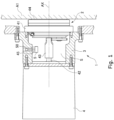
- Fig. 1 is a sectional view showing one example of a mechanism 1 including a sensor 5 relating to one embodiment of the present invention.
- the mechanism 1 is, for example, a moving part such as a robot arm.
- the mechanism 1 includes a speed reducer 2, a flange 3 provided on the input side, a servomotor 4, and a device A1 provided on the output side.
- the speed reducer 2 includes a casing 41 mounted to the flange 3, an input shaft 43 connected to an output shaft 42 of the servomotor 4, and an output shaft 24 connected to the output-side device A1.
- the input shaft 43 and the output shaft 44 are supported such that they are rotatable about an axis AX relative to the casing 41.
- the output from the servomotor 4 is input to the speed reducer 2 via the input shaft 43, reduced by the speed reducer 2, and then transmitted to the output-side device A1 via the output shaft 44.
- the output-side device A1 and the flange 3 are capable of rotating relative to each other.
- the flange 3 is a tubular member and houses at least part of the speed reducer 2.
- the servomotor 4 is mounted to the flange 3.
- An opening in one end of the flange 3 in a direction along the axis AX is closed by the speed reducer 2, and an opening in the other end is closed by the servomotor 4.
- the flange 3 has a tightly closed hollow portion (a space S) formed therein.
- the space S contains therein a lubricant oil, so that the flange 3 also serves as an oil bath.
- the casing 41 of the speed reducer 2 houses therein a gear mechanism, for example.
- the space within the casing 41 communicates with the space S within the flange 3.
- the gear mechanism in the casing 41 rotates, which subsequently causes the lubricant oil to circulate between the space in the casing 41 and the space S in the flange 10.
- a conductive substance such as abrasion powder generated in the speed reducer 2 is discharged into the space S in the flange 3.
- a sensor 5 is installed for sensing the amount of the conductive substance contained in the lubricant oil.
- the sensor 5 is fixedly attached onto the flange 3 via, for example, a support member 45.
- the sensor 5 includes a magnet for attracting the conductive substance contained in the lubricant oil, so that the conductive substance accumulates between electrodes.
- the sensor 5 senses the amount of the conductive substance in the lubricant oil based on a change in electrical resistance between the electrodes.
- the sensor 5 may be alternatively positioned, for example, inside the casing 41 but can be at any position in the mechanism 1 as long as it is positioned within the space containing therein the lubricant oil.
- Fig. 2 illustrates the structure of the sensor 5 according to one embodiment of the invention.
- Fig. 2 shows a top view of the sensor 5 and a sectional view thereof along the A-A line in the top view.
- the senor 5 has a substantially columnar outer shape and includes a plurality of detecting units and a sensing unit 50 (see Fig. 1 ) configured to output a signal when the detecting units experience a change in electrical resistance.
- the detecting units each includes a pair of electrodes and a detecting area for causing a change in electrical resistance between the paired electrodes as a conductive particle accumulates.
- the sensor 5 includes a first electrode (center electrode) 6 positioned in the vicinity of the center, a second electrode (outer electrode) 7 positioned on the outer side, a third electrode (outer electrode) 8, a fourth electrode (center electrode) 9 positioned in the vicinity of the center, a fifth electrode (outer electrode) 10 positioned on the outer side, a sixth electrode (outer electrode) 11, a magnet 40, a fastening member 12, and a resin member 13.
- the center electrodes 6 and 9 are positioned on the inner side relative to the outer electrodes 7, 8, 10 and 11 and spaced away from the outer electrodes 7, 8, 10 and 11. In this way, a plurality of detecting areas are formed in the resin member 13 in the upper portion thereof between (i) the center electrodes 6 and 9 and (ii) the outer electrodes 7, 8, 10 and 11.
- the sensor 5 includes four detecting units, and four detecting areas are formed in the upper portion of the resin member 13: a first detecting area GA1, a second detecting area GA2, a third detecting area GA3, and a fourth detecting area GA4.
- a first detecting unit is constituted by the first electrode 6, the second electrode 7, and the first detecting area GA1 formed between the first and second electrodes 6 and 7.
- a second detecting unit is constituted by the first electrode 6, the third electrode 8, and the second detecting area GA2 formed between the first and third electrodes 6 and 8.
- a third detecting unit is constituted by the fourth electrode 9, the fifth electrode 10, and the third detecting area GA3 formed between the fourth and fifth electrodes 9 and 10.
- a fourth detecting unit is constituted by the fourth electrode 9, the sixth electrode 11, and the fourth detecting area GA4 formed between the fourth and sixth electrodes 9 and 11. It should be noted that the magnet 40 may not be used, in which case the center electrode 6 may be configured to serve not only as the electrode and but also as the magnet 40.
- the electrodes are magnetic members formed of an electrically conductive magnetic material such as iron, ferrite, or silicon steel. Between the electrodes, there is disposed the resin material 13, which is a non-magnetic material (an insulator). The electrodes and magnet 40 are buried at least partly in the central region of the resin member.
- the shape of the electrodes and magnet 40 is not limited to the illustrated example, and the electrodes and magnet 40 can be shaped variously.
- the center electrodes 6 and 9 and the outer electrodes 7, 8, 10 and 11 are each connected to an output line (not shown).
- the magnet 40 may or may not be attached to, for example, the bottom of the center electrodes 6 and 9.
- the magnet 40 is formed of a magnet or electromagnet, and the magnet may be covered with a nonmagnetic material such as copper and a signal line (not shown) may be connected to the covering layer.
- the magnet 40 forms lines of magnetic flux around the detecting areas GA1, GA2, GA3 and GA4.
- the conductive substance contained in the lubricant oil is gathered to the vicinity of the detecting areas GA1, GA2, GA3 and GA4.
- the sensor 5 is connected to the sensing unit 50 including a sensor drive circuit (not shown) that monitors the resistance of the sensor 5 to predict a failure of the mechanical parts based on a change in the resistance caused by the accumulation of the conductive substance between the electrodes.
- a sensor drive circuit (not shown) that monitors the resistance of the sensor 5 to predict a failure of the mechanical parts based on a change in the resistance caused by the accumulation of the conductive substance between the electrodes.
- the sensor drive circuit in the sensing unit 50 detects the change in the electrical resistance to predict a failure of the mechanical parts.
- the drop in electrical resistance may be indicated by an ON/OFF signal determined by whether electrical connection is established or not, so that the drop in electrical resistance may be sensed between the two states of electrical disconnection and electrical connection (hereinafter referred to as "digital sensing").
- the sensor drive circuit is connected to a higher-level control device such as a manipulator in a wired or wireless manner.
- a circuit board 43 shown in Fig. 1 may transmit the output on the output line (the output from the sensor [[40A]] 5) to the higher-level control device either constantly or intermittently (at predetermined time intervals) for saving electricity.
- the higher-level control device may be configured to issue a warning via a predetermined notification unit (a display or voice output device) for demanding maintenance of, for example, the speed reducer 2.
- a predetermined notification unit a display or voice output device
- the fifth electrode (outer electrode) 10 positioned on the outer side is connected to a detector circuit 17 via a connection line 15, and the second electrode (outer electrode) 7 positioned on the outer side is connected to the detector circuit 17 via a connection line 16.
- the third electrode (outer electrode) 8 and the sixth electrode (outer electrode) 11 are connected to each other via a connection line 14.
- the sensor 5 can be configured such that a logical AND can be obtained between four circuits in the order of the fifth electrode (outer electrode) 10, fourth electrode (center electrode) 9 in the vicinity of the center, sixth electrode (outer electrode ) 11, third electrode (outer electrode) 8, the first electrode (center electrode) 6 in the vicinity of the center, and second electrode (outer electrode) 7.
- a logical AND can be obtained between four circuits in the order of the fifth electrode (outer electrode) 10, fourth electrode (center electrode) 9 in the vicinity of the center, sixth electrode (outer electrode ) 11, third electrode (outer electrode) 8, the first electrode (center electrode) 6 in the vicinity of the center, and second electrode (outer electrode) 7.
- Such a configuration can be achieved with a reduced number of lead wires, or requires only two lead wires.
- the first and fourth electrodes (center electrodes) 6 and 9 in the vicinity of the center are integrally formed, five lead wires are required to take care of the respective outer electrodes 7, 8 , 10 and 11. With the above-described configuration,
- the first detecting area GA1 between the first electrode (center electrode) 6 in the vicinity of the center and the second electrode (outer electrode) 7, the second detecting area GA2 between the first electrode (center electrode) 6 in the vicinity of the center and the third electrode (outer electrode) 8, the third detecting area GA3 between the fourth electrode (center electrode) 9 in the vicinity of the center and the fifth electrode (outer electrode) 10, and the fourth detecting area GA4 between the fourth electrode (center electrode ) 9 in the vicinity of the center and the sixth electrode (outer electrode) 11 are connected in series to constitute a circuit.
- the present embodiment can prevent a foreign substance from causing the sensor 5 to unexpectedly operating. Specifically, cutting chips or the like may possibly remain in the lubricant oil, but the detector circuit can avoid transmitting an erroneous signal unless the cutting chips adhere to all of the detecting areas.
- an array of sensors (a group of sensors) constituted by a plurality of sensors with reference to Fig. 4 .
- a plurality of sensors 5 are provided at different detecting positions.
- an array of sensors (a group of sensors ) includes two sensors 5 and is configured such that the sensors 5 can respectively detect the amount of conductive substance at two detecting positions.
- the numbers of detecting positions and sensors 5 are not limited to such and may be changed as the case may be. For example, in a case where the lubricant oil is contained in a space S (see Fig. 1 ) having a sufficiently large volume, a single sensor 5 may encounter difficulties in successful sensing. If a plurality of detecting positions are defined and one or more sensors are provided at each detecting position, the sensing can be accurately performed.
- the two sensors 5 are connected in series to constitute a circuit as illustrated. Since the two sensors 5 are arranged in series, the conductive substance adhering to the sensor 5 in only one of the detecting areas is not enough to cause current to flow through the circuit, and current flows through the circuit only if the conductive substance adheres also to the sensor 5 in the other detecting area. In this manner, the array of sensors relating to one embodiment of the present invention can reliably avoid making an output relating to failure prediction when one of the sensors 5 erroneously predict failure.
- connection lines 24, 25 and 26 are connected to the sixth electrode 11 in series using a connection line 28.
- the electrodes 7, 8, 10 and 11 are connected to a detector circuit 29 including a voltage source.
- one of the four outer electrodes i.e., the second, third, fifth and sixth electrodes 7,.8, 10 and 11
- the remaining three outer electrodes can be used as a signal.
- Electrical connection is established between the first and fourth electrodes 6 and 9 as conductive particles accumulate.
- the centrally arranged circular electrode connects together the two sections of the sensor 5 in series, one of which includes the three elements connected in parallel. With such configuration, the voltage can be approximately halved and improved robustness can be resultantly achieved against disconnection.
- the sensor 5 shown in Fig. 6 has the same configuration as the sensor shown in Fig. 3 , but is connected to a detector circuit in a different manner than in Fig. 3 .
- the second, third, fifth and sixth electrodes 7, 8, 10 and 11 are connected in parallel using connection lines 18, 19, 20 and 21, and these electrodes are connected to a detector circuit 23 including a voltage source.
- the voltage can be approximately quartered when compared with the case where the four outer electrodes are connected in series with each other.
- improved robustness can be achieved against disconnection since the Gnd line is multiplexed
- Fig. 7 shows a top view of a sensor 5 according to another embodiment of the invention and a sectional view taken along the line A-A.
- the senor 5 includes a first electrode (center electrode) 6 in the vicinity of the center, a second electrode (outer electrode) 7 positioned on the outer side, a third electrode (outer electrode) 8, a fourth electrode (center electrode) 9 in the vicinity of the center, a fifth electrode (outer electrode) 10 positioned on the outer side, a sixth electrode (outer electrode) 11, a magnet 40, a fastening member 12 and a resin member 13.
- resistors 30 are provided on the resin member 13 such that they are respectively positioned between the first electrode (center electrode) 6 and the second electrode (outer electrode) 7, between the first electrode (center electrode) 6 and the third electrode (outer electrode) 8, between the fourth electrode (center electrode) 9 and the fifth electrode (outer electrode) 10, and between the fourth electrode (center electrode) 9 and the sixth electrode (outer electrode) 11.
- a plurality of detecting units included in the sensor 5 each further include the resistor 30 for allowing a small current to flow between the electrodes constituting the detecting unit.
- Fig. 7 shows only an example of how the resistors 40 can be arranged.
- the shape, structure, location and arrangement of the resistors 30 are not limited in any particular manner and can be changed as the case may be.
- detecting areas GA1, GA2, GA3 and GA4 of the sensor 5 each has the resistor 30 exhibiting high resistance connected thereto.
- a small current can flow between the electrodes via the resistor 30 if only a small amount of conductive substance accumulates.
- the small current stops flowing if the copper lines (the connection lines and the like) are broken. Accordingly, disconnection of the circuit can be detected.
- the resistance R of the resistor 30 is sufficiently higher than the resistance ⁇ exhibited by the gap portion when a failure is detected. If the speed reducer fails, the conductive substance gathers resultantly, the resistance of the detecting areas then drops, and a large current is allowed to flow.
- a threshold value may be set for the current, so that the failure can be predicted.
- the conductive substance adheres to the sensor to such an extent that the current exceeds the threshold the sensor may be resultantly turned on. This causes the current to flow constantly and may possibly waste the energy. In addition, this may affect the lifetime of a photo coupler (PC) and cause problems such as breakage of the circuit since the lifetime of the photo coupler (PC) correlatively depends on the duration of the current flow.
- PC photo coupler
- Fig. 8 is used to illustrate the configuration of a signal processing circuit provided to overcome such problems.
- the sensor 5 is connected via a connection line to a power application controller unit 31 including a power source 32 and then to a voltage detector unit 33, a storage unit 34 and an output unit 35.
- the storage unit 34 is connected to the power application controller unit 31 via a connection line.
- the power application controller unit 31 shown includes the power source 32 configured to apply voltage between the electrodes of the sensor 5, and is configured to stop the application of the voltage by the power source 32.
- the voltage detector unit 33 is configured to detect whether the power source 32 applies voltage and outputs a sensing signal in response to detecting the application.
- the storage unit 34 stores the output sensing signal if the voltagae detector unit 33outputs the sensing signal.
- the storage unit 34 shown indicates an RS flip-flop storing a state, but may be alternatively an integrated device including, for example, a memory of a microcomputer or configured in any other manners. Once the storage unit 34 stores thereon the sensing signal, the output unit 35 outputs indication indicating that the sensing signal has been output and generates a trigger for a warning indicating predicted failure.
- the output unit 33 If the amount of the conductive substance adhering to the sensor 5 relating to one embodiment of the present invention exceeds a threshold, current flows between the sensor 5 and the power source 32 (the ON state). Once detecting the ON state, the detector unit 33 outputs a sensing signal to the storage unit 34, and the storage unit 34 stores the sensing signal. Once storing the sensing signal, the storage unit 34 enters the Hi state. As a result, the power application controller unit 31 also enters the Hi state, which stops the application of the voltage and turns off a PC1. This turns off the power fed to the sensor 5. Accordingly, the output from the detector unit 33 to the storage unit 34 changes, but the circuit of the storage unit 34 is configured such that the output from the storage unit 34 remains unchanged. Therefore, the output unit keeps generating a trigger for a warning indicating predicted failure.
- the present embodiment can prevent current from continuously flowing through the circuit and thus achieve an extended lifetime for the photocouplers (PC), thereby avoiding breakage of the circuit.
- Fig. 9 is used to illustrate a different configuration of the signal processing circuit.
- the sensor 5 is connected via a connection line to a power application controller unit 31 including a power source 32 and then to a voltage detector unit 33, a storage unit 34 and an output unit 35.
- the storage unit 34 is connected to the power application controller unit 31 via a connection line.
- a timer circuit 36 is connected between the storage unit 34 and the power application controller unit 31.
- the power application controller unit 31 shown includes the power source 32 configured to apply voltage between the electrodes of the sensor 5, and is configured to stop the application of the voltage by the power source 32.
- the voltage detector unit 33 is configured to detect whether the power source 32 applies voltage and outputs a sensing signal in response to detecting the application.
- the storage unit 34 stores the output sensing signal if the voltage detector unit 33 outputs the sensing signal.
- the storage unit 34 shown indicates an RS flip-flop storing a state, but may be alternatively an integrated device including, for example, a memory of a microcomputer or configured in any other manners. Once the storage unit 34 stores thereon the sensing signal, the output unit 35 outputs indication indicating that the sensing signal has been output and generates a trigger for a warning indicating predicted failure.
- the amount of the conductive substance adhering to the sensor 5 relating to one embodiment of the present invention exceeds a threshold, current flows between the sensor 5 and the power source 32 (the ON state). Once detecting the ON state, the detector unit 33 outputs a sensing signal to the storage unit 34, and the storage unit 34 stores the sensing signal. Since the conductive substance typically tends to increase gradually, it is not necessarily required to keep applying voltage constantly to the sensor 5 to keep monitoring the sensor 5. Intermittent monitoring is effectively used to predict a failure.
- the signal processing circuit shown in Fig. 9 additionally includes the timer circuit 36, so that the voltage is applied at predetermined time intervals or at every predetermined time. In this manner, the present embodiment can prevent current from continuously flowing through the circuit, thereby reducing energy consumption.
Landscapes
- Chemical & Material Sciences (AREA)
- Life Sciences & Earth Sciences (AREA)
- Health & Medical Sciences (AREA)
- Physics & Mathematics (AREA)
- General Physics & Mathematics (AREA)
- Pathology (AREA)
- Immunology (AREA)
- Analytical Chemistry (AREA)
- Biochemistry (AREA)
- General Health & Medical Sciences (AREA)
- Chemical Kinetics & Catalysis (AREA)
- Engineering & Computer Science (AREA)
- Electrochemistry (AREA)
- Oil, Petroleum & Natural Gas (AREA)
- Medicinal Chemistry (AREA)
- Food Science & Technology (AREA)
- General Chemical & Material Sciences (AREA)
- Dispersion Chemistry (AREA)
- Investigating Or Analyzing Materials By The Use Of Electric Means (AREA)
Claims (8)
- Sensor (5), der umfasst:eine Vielzahl von Erfassungs-Einheiten, die jeweils ein Paar Elektroden und einen Erfassungsbereich (GA1, GA2, GA3, GA4) enthalten, der zwischen den Elektroden vorhanden ist, wobei der Erfassungsbereich so ausgeführt ist, dass er eine Änderung von elektrischem Widerstand zwischen den Elektroden bewirkt, wenn sich leitende Teilchen zwischen den Elektroden akkumulieren;eine Mess-Einheit, mit der ein Mess-Signal ausgegeben wird, wenn an wenigstens zwei oder mehr der Erfassungs-Einheiten eine Änderung von elektrischem Widerstand auftritt;eine Stromquelle (32) zum Anlegen von Spannung an die Vielzahl von Erfassungs-Einheiten; sowieeine Signalerfassungs-Einheit (33), mit der erfasst wird, ob das Mess-Signal ausgegeben wird;gekennzeichnet durcheine Steuerungs-Einheit (31) für Anlegen von Spannung, die die Stromquelle (32) einschließt; undeine Speicherungs-Einheit (34), die, wenn das Mess-Signal ausgegeben wird, einen Hinweis darauf speichert, dass das Mess-Signal ausgegeben wird,wobei die Steuerungs-Einheit (31) für Anlegen von Spannung das Anlegen der Spannung durch die Stromquelle (32) unterbricht, wenn die Speicherungs-Einheit (34) den Hinweis darauf speichert, dass das Mess-Signal ausgegeben wird.
- Sensor (5) nach Anspruch 1,wobei die Vielzahl von Erfassungs-Einheiten eine erste Erfassungs-Einheit und eine zweite Erfassungs-Einheit einschließt,die erste Erfassungs-Einheit durch eine erste Elektrode (6), eine zweite Elektrode (7) sowie einen ersten Erfassungs-Bereich (GA1) gebildet wird, der zwischen der ersten Elektrode (6) und der zweiten Elektrode (7) ausgebildet ist, undwobei die zweite Erfassungs-Einheit durch die erste Elektrode (6), eine dritte Elektrode (8) sowie einen zweiten Erfassungs-Bereich (GA2) gebildet wird, der zwischen der ersten Elektrode (6) und der dritten Elektrode (8) ausgebildet ist.
- Sensor (5) nach Anspruch 2,wobei die Vielzahl von Erfassungs-Einheiten eine dritte Erfassungs-Einheit und eine vierte Erfassungs-Einheit einschließt,wobei die dritte Erfassungs-Einheit durch eine vierte Elektrode (9), eine fünfte Elektrode (10) sowie einen dritten Erfassungs-Bereich (GA3) gebildet wird, der zwischen der vierten Elektrode (9) und der fünften Elektrode (10) ausgebildet ist, undwobei die vierte Erfassungs-Einheit durch die vierte Elektrode (9), eine sechste Elektrode (11) sowie einen vierten Erfassungs-Bereich (GA4) gebildet wird, der zwischen der vierten Elektrode (9) und der sechsten Elektrode (11) ausgebildet ist.
- Sensor (5) nach einem der Ansprüche 1 bis 3, wobei die Vielzahl von Erfassungs-Einheiten in Reihe miteinander verbunden sind.
- Sensor (5) nach einem der Ansprüche 1 bis 3, wobei die Vielzahl von Erfassungs-Einheiten parallel miteinander verbunden sind.
- Sensor (5) nach einem der Ansprüche 1 bis 5, wobei die Vielzahl von Erfassungs-Einheiten jeweils einen Widerstand (30) enthalten, der geringen Stromfluss zwischen den Elektroden zulässt.
- Sensor (5) nach Anspruch 3,wobei die zweite Elektrode (7) radial außerhalb der ersten Elektrode (6) angeordnet ist und die dritte Elektrode (8) radial außerhalb der ersten Elektrode (6) angeordnet ist,die vierte Elektrode (9) in Umfangsrichtung von der ersten Elektrode (6) entfernt angeordnet ist,die fünfte Elektrode (10) radial außerhalb der vierten Elektrode (9) angeordnet ist,die sechste Elektrode (11) radial außerhalb der vierten Elektrode (9) und in Umfangsrichtung von der fünften Elektrode (10) entfernt angeordnet ist,der erste Erfassungs-Bereich (GA1), der zweite Erfassungs-Bereich (GA2), der dritte Erfassungs-Bereich (GA3) und der vierte Erfassungs-Bereich (GA4) in Reihe verbunden sind, undwobei die Stromquelle (31) die Spannung zwischen der zweiten Elektrode (7) und der fünften Elektrode (10) anlegt.
- Sensor-Anordnung, die eine Vielzahl von Sensoren umfasst, wobei jeder Sensor der Sensor nach einem der Ansprüche 1 bis 7 ist und die Vielzahl von Sensoren an unterschiedlichen Erfassungspositionen vorhanden sind.
Applications Claiming Priority (1)
| Application Number | Priority Date | Filing Date | Title |
|---|---|---|---|
| PCT/JP2019/018107 WO2020217508A1 (ja) | 2019-04-26 | 2019-04-26 | センサ |
Publications (3)
| Publication Number | Publication Date |
|---|---|
| EP3961201A1 EP3961201A1 (de) | 2022-03-02 |
| EP3961201A4 EP3961201A4 (de) | 2022-11-09 |
| EP3961201B1 true EP3961201B1 (de) | 2025-02-26 |
Family
ID=72941326
Family Applications (1)
| Application Number | Title | Priority Date | Filing Date |
|---|---|---|---|
| EP19926223.9A Active EP3961201B1 (de) | 2019-04-26 | 2019-04-26 | Sensor |
Country Status (5)
| Country | Link |
|---|---|
| US (1) | US12270775B2 (de) |
| EP (1) | EP3961201B1 (de) |
| KR (1) | KR20220005467A (de) |
| CN (1) | CN113728225B (de) |
| WO (1) | WO2020217508A1 (de) |
Families Citing this family (2)
| Publication number | Priority date | Publication date | Assignee | Title |
|---|---|---|---|---|
| EP3961201B1 (de) * | 2019-04-26 | 2025-02-26 | Nabtesco Corporation | Sensor |
| CN111855755B (zh) * | 2019-04-26 | 2024-12-17 | 纳博特斯克有限公司 | 传感器 |
Family Cites Families (58)
| Publication number | Priority date | Publication date | Assignee | Title |
|---|---|---|---|---|
| JPH01235107A (ja) | 1988-03-15 | 1989-09-20 | Mitsubishi Electric Corp | 断線監視装置 |
| US5179346A (en) * | 1991-05-24 | 1993-01-12 | Caterpillar, Inc. | Conductive particle sensor using a magnet |
| JPH06148109A (ja) * | 1992-11-10 | 1994-05-27 | Taisee:Kk | ガスセンサ温度制御装置 |
| JPH06148019A (ja) * | 1992-11-10 | 1994-05-27 | Shimadzu Corp | 動釣合試験機 |
| US5402113A (en) * | 1993-08-30 | 1995-03-28 | Amot Controls Corporation | Metal particle detector apparatus for non-conducting fluid systems |
| US5527446A (en) * | 1995-04-13 | 1996-06-18 | United States Of America As Represented By The Secretary Of The Air Force | Gas sensor |
| GB9803158D0 (en) * | 1998-02-13 | 1998-04-08 | City Tech | Gas or vapour sensor |
| JP3961226B2 (ja) | 2001-03-22 | 2007-08-22 | Ntn株式会社 | オイルチェックセンサ |
| JP4557456B2 (ja) * | 2001-04-06 | 2010-10-06 | 株式会社小松製作所 | 導電体検出装置 |
| JP4260053B2 (ja) * | 2004-03-26 | 2009-04-30 | Ntn株式会社 | オイルチェックセンサ |
| JP2005331324A (ja) * | 2004-05-19 | 2005-12-02 | Ntn Corp | オイルチェックセンサ |
| JP2005337981A (ja) * | 2004-05-28 | 2005-12-08 | Ntn Corp | オイルチェックセンサ |
| JP2005337945A (ja) * | 2004-05-28 | 2005-12-08 | Ntn Corp | オイルチェックセンサ |
| JP2005337938A (ja) * | 2004-05-28 | 2005-12-08 | Ntn Corp | オイルチェックセンサ |
| JP2006052989A (ja) * | 2004-08-10 | 2006-02-23 | Ntn Corp | Rfid用タグを内蔵したオイルチェックセンサ |
| JP4643243B2 (ja) * | 2004-12-13 | 2011-03-02 | Ntn株式会社 | オイルチェックセンサ |
| JP4711723B2 (ja) * | 2005-04-18 | 2011-06-29 | Ntn株式会社 | オイルチェックセンサ |
| JP2006300608A (ja) * | 2005-04-18 | 2006-11-02 | Ntn Corp | オイルチェックセンサ |
| FR2927401B1 (fr) * | 2008-02-13 | 2010-05-28 | Turbomeca | Bouchon magnetique a pre-signalisation. |
| JP2010014518A (ja) * | 2008-07-03 | 2010-01-21 | Hitachi Constr Mach Co Ltd | 金属粒子検出装置 |
| JP2010014519A (ja) * | 2008-07-03 | 2010-01-21 | Hitachi Constr Mach Co Ltd | 金属粒子検出装置 |
| JP2011007610A (ja) * | 2009-06-25 | 2011-01-13 | Ntn Corp | オイルチェックセンサ |
| JP2011203093A (ja) * | 2010-03-25 | 2011-10-13 | Denso Corp | ガスセンサとガスセンサの断線検出方法 |
| JP5327152B2 (ja) * | 2010-07-05 | 2013-10-30 | 株式会社デンソー | 粒子状物質検出センサ素子及び粒子状物質検出センサ |
| JP5201193B2 (ja) * | 2010-10-28 | 2013-06-05 | 株式会社デンソー | 粒子状物質検出センサ |
| DE102013212696A1 (de) * | 2013-06-28 | 2014-12-31 | Robert Bosch Gmbh | Vorrichtung zum Erfassen von metallischen ferromagnetischen Partikeln in einem Fluid |
| EP3049900B1 (de) * | 2013-09-27 | 2020-11-18 | Sensel, Inc. | Berührungssensor-detektorsysteme und verfahren |
| KR20160116738A (ko) * | 2015-03-31 | 2016-10-10 | 제주대학교 산학협력단 | 정전용량 측정에 기반한 차량 엔진 오일 감시 센서 |
| CN107923569B (zh) * | 2015-08-05 | 2020-10-27 | Ntn株式会社 | 滚动轴承的异常检测装置 |
| DK4027137T3 (da) * | 2015-12-18 | 2025-03-31 | Radiometer Medical Aps | Blandet ionofor ion-selektiv elektrode til forbedret detektion af urea i blod |
| JP6707389B2 (ja) * | 2016-04-12 | 2020-06-10 | Ntn株式会社 | 転がり軸受ユニット |
| CN107315033B (zh) * | 2016-04-26 | 2021-08-06 | 新唐科技日本株式会社 | 气体检测装置以及氢检测方法 |
| DE102016107888A1 (de) * | 2016-04-28 | 2017-11-02 | Heraeus Sensor Technology Gmbh | Sensor zur Detektion elektrisch leitfähiger und/oder polarisierbarer Partikel, Sensorsystem, Verfahren zum Betreiben eines Sensors und Verwendung eines derartigen Sensors |
| US10317354B2 (en) * | 2016-08-01 | 2019-06-11 | Pratt & Whitney Canada Corp. | Systems and methods for detecting chips in fluid of aircraft engine |
| US10705039B2 (en) * | 2017-03-27 | 2020-07-07 | Nabtesco Corporation | Sensor for detecting magnetic powders in a lubricant |
| JP7094081B2 (ja) * | 2017-03-27 | 2022-07-01 | ナブテスコ株式会社 | センサ |
| DE102017110088A1 (de) * | 2017-05-10 | 2018-05-24 | Schaeffler Technologies AG & Co. KG | Sensor, Sensormodul und Sensorbaukasten mit diesem Sensor |
| WO2018216561A1 (ja) | 2017-05-26 | 2018-11-29 | 株式会社デンソー | 粒子状物質検出システム |
| JP6859971B2 (ja) * | 2017-05-26 | 2021-04-14 | 株式会社デンソー | 粒子状物質検出システム |
| DE102017213765A1 (de) * | 2017-08-08 | 2019-02-14 | Robert Bosch Gmbh | Sensorelement zur Detektion von Teilchen |
| JP7086578B2 (ja) * | 2017-11-22 | 2022-06-20 | ナブテスコ株式会社 | センサ |
| JP7101486B2 (ja) * | 2018-01-26 | 2022-07-15 | ナブテスコ株式会社 | センサ |
| KR102733959B1 (ko) * | 2018-04-20 | 2024-11-22 | 가부시키가이샤 아타고 | 오일열화 검출장치, 오일열화 검출장치의 센서 커버, 및 오일열화도 측정 방법 |
| CN116189963A (zh) * | 2018-06-25 | 2023-05-30 | 积水化学工业株式会社 | 导电性粒子、导电材料以及连接结构体 |
| US20200057044A1 (en) * | 2018-08-20 | 2020-02-20 | Nabtesco Corporation | Industrial device including sensor |
| DE102018219625A1 (de) * | 2018-11-16 | 2020-05-20 | Robert Bosch Gmbh | Verfahren zum Bewerten der Funktionsfähigkeit eines Sensors zur Detektion von Ruß |
| CN120464337A (zh) * | 2019-03-13 | 2025-08-12 | 株式会社力森诺科 | 电路连接用黏合剂膜及电路连接结构体的制造方法 |
| EP3961201B1 (de) * | 2019-04-26 | 2025-02-26 | Nabtesco Corporation | Sensor |
| CN111855755B (zh) * | 2019-04-26 | 2024-12-17 | 纳博特斯克有限公司 | 传感器 |
| JP7452980B2 (ja) * | 2019-04-26 | 2024-03-19 | ナブテスコ株式会社 | センサ |
| JP7463069B2 (ja) * | 2019-09-30 | 2024-04-08 | 積水化学工業株式会社 | 導電性粒子、導電材料、接続構造体及び接続構造体の製造方法 |
| JP7536439B2 (ja) * | 2019-11-05 | 2024-08-20 | ナブテスコ株式会社 | センサ |
| JP7366731B2 (ja) * | 2019-12-17 | 2023-10-23 | ナブテスコ株式会社 | センサ |
| US11549933B2 (en) * | 2020-02-24 | 2023-01-10 | Pratt & Whitney Canada Corp. | Magnetic chip detector and method of use |
| DE102020205944A1 (de) * | 2020-05-12 | 2021-11-18 | Robert Bosch Gesellschaft mit beschränkter Haftung | Sensor zur Erfassung mindestens einer Eigenschaft eines Messgases |
| JP7604276B2 (ja) * | 2021-03-12 | 2024-12-23 | ナブテスコ株式会社 | 導電性粒体検出装置、及び、減速機 |
| JP7620455B2 (ja) * | 2021-03-12 | 2025-01-23 | ナブテスコ株式会社 | 導電性粒体検出装置、及び、機械動作装置 |
| DE102021117863A1 (de) * | 2021-07-09 | 2023-01-12 | Chian-Yeu Chien | Elektrisches messgerät für die messung von metallverunreinigungen in einem kraftstofftank |
-
2019
- 2019-04-26 EP EP19926223.9A patent/EP3961201B1/de active Active
- 2019-04-26 CN CN201980095788.XA patent/CN113728225B/zh active Active
- 2019-04-26 US US17/598,708 patent/US12270775B2/en active Active
- 2019-04-26 WO PCT/JP2019/018107 patent/WO2020217508A1/ja not_active Ceased
- 2019-04-26 KR KR1020217034531A patent/KR20220005467A/ko not_active Withdrawn
Also Published As
| Publication number | Publication date |
|---|---|
| WO2020217508A1 (ja) | 2020-10-29 |
| CN113728225B (zh) | 2024-08-06 |
| US12270775B2 (en) | 2025-04-08 |
| US20220178857A1 (en) | 2022-06-09 |
| CN113728225A (zh) | 2021-11-30 |
| EP3961201A1 (de) | 2022-03-02 |
| EP3961201A4 (de) | 2022-11-09 |
| KR20220005467A (ko) | 2022-01-13 |
Similar Documents
| Publication | Publication Date | Title |
|---|---|---|
| JP7101486B2 (ja) | センサ | |
| JP7723723B2 (ja) | センサ | |
| US6788212B2 (en) | Conductor detecting device | |
| EP3839504B1 (de) | Sensor | |
| EP3623803B1 (de) | Industrielle vorrichtung umfassend einen sensor zur erfassung einer leitfähigen substanz in einem schmiermittel | |
| TWI802614B (zh) | 感測器及機構 | |
| US12038400B2 (en) | Sensor | |
| EP3961201B1 (de) | Sensor | |
| US11346871B2 (en) | Sensor | |
| JP7319131B2 (ja) | センサを備えた産業装置 | |
| TWI811352B (zh) | 感測器及感測器排列 |
Legal Events
| Date | Code | Title | Description |
|---|---|---|---|
| STAA | Information on the status of an ep patent application or granted ep patent |
Free format text: STATUS: THE INTERNATIONAL PUBLICATION HAS BEEN MADE |
|
| PUAI | Public reference made under article 153(3) epc to a published international application that has entered the european phase |
Free format text: ORIGINAL CODE: 0009012 |
|
| STAA | Information on the status of an ep patent application or granted ep patent |
Free format text: STATUS: REQUEST FOR EXAMINATION WAS MADE |
|
| 17P | Request for examination filed |
Effective date: 20211029 |
|
| AK | Designated contracting states |
Kind code of ref document: A1 Designated state(s): AL AT BE BG CH CY CZ DE DK EE ES FI FR GB GR HR HU IE IS IT LI LT LU LV MC MK MT NL NO PL PT RO RS SE SI SK SM TR |
|
| DAV | Request for validation of the european patent (deleted) | ||
| DAX | Request for extension of the european patent (deleted) | ||
| REG | Reference to a national code |
Ref legal event code: R079 Ipc: G01N0027120000 Ref country code: DE Ref legal event code: R079 Ref document number: 602019066682 Country of ref document: DE Free format text: PREVIOUS MAIN CLASS: G01N0027060000 Ipc: G01N0027120000 |
|
| A4 | Supplementary search report drawn up and despatched |
Effective date: 20221010 |
|
| RIC1 | Information provided on ipc code assigned before grant |
Ipc: G01N 15/06 20060101ALI20221004BHEP Ipc: G01N 33/28 20060101ALI20221004BHEP Ipc: G01N 27/12 20060101AFI20221004BHEP |
|
| P01 | Opt-out of the competence of the unified patent court (upc) registered |
Effective date: 20230523 |
|
| GRAP | Despatch of communication of intention to grant a patent |
Free format text: ORIGINAL CODE: EPIDOSNIGR1 |
|
| STAA | Information on the status of an ep patent application or granted ep patent |
Free format text: STATUS: GRANT OF PATENT IS INTENDED |
|
| INTG | Intention to grant announced |
Effective date: 20241105 |
|
| GRAS | Grant fee paid |
Free format text: ORIGINAL CODE: EPIDOSNIGR3 |
|
| GRAA | (expected) grant |
Free format text: ORIGINAL CODE: 0009210 |
|
| STAA | Information on the status of an ep patent application or granted ep patent |
Free format text: STATUS: THE PATENT HAS BEEN GRANTED |
|
| AK | Designated contracting states |
Kind code of ref document: B1 Designated state(s): AL AT BE BG CH CY CZ DE DK EE ES FI FR GB GR HR HU IE IS IT LI LT LU LV MC MK MT NL NO PL PT RO RS SE SI SK SM TR |
|
| REG | Reference to a national code |
Ref country code: GB Ref legal event code: FG4D |
|
| REG | Reference to a national code |
Ref country code: CH Ref legal event code: EP |
|
| REG | Reference to a national code |
Ref country code: DE Ref legal event code: R096 Ref document number: 602019066682 Country of ref document: DE |
|
| REG | Reference to a national code |
Ref country code: IE Ref legal event code: FG4D |
|
| REG | Reference to a national code |
Ref country code: NL Ref legal event code: MP Effective date: 20250226 |
|
| PG25 | Lapsed in a contracting state [announced via postgrant information from national office to epo] |
Ref country code: RS Free format text: LAPSE BECAUSE OF FAILURE TO SUBMIT A TRANSLATION OF THE DESCRIPTION OR TO PAY THE FEE WITHIN THE PRESCRIBED TIME-LIMIT Effective date: 20250526 |
|
| PG25 | Lapsed in a contracting state [announced via postgrant information from national office to epo] |
Ref country code: FI Free format text: LAPSE BECAUSE OF FAILURE TO SUBMIT A TRANSLATION OF THE DESCRIPTION OR TO PAY THE FEE WITHIN THE PRESCRIBED TIME-LIMIT Effective date: 20250226 |
|
| PG25 | Lapsed in a contracting state [announced via postgrant information from national office to epo] |
Ref country code: PL Free format text: LAPSE BECAUSE OF FAILURE TO SUBMIT A TRANSLATION OF THE DESCRIPTION OR TO PAY THE FEE WITHIN THE PRESCRIBED TIME-LIMIT Effective date: 20250226 |
|
| PGFP | Annual fee paid to national office [announced via postgrant information from national office to epo] |
Ref country code: DE Payment date: 20250425 Year of fee payment: 7 |
|
| PG25 | Lapsed in a contracting state [announced via postgrant information from national office to epo] |
Ref country code: ES Free format text: LAPSE BECAUSE OF FAILURE TO SUBMIT A TRANSLATION OF THE DESCRIPTION OR TO PAY THE FEE WITHIN THE PRESCRIBED TIME-LIMIT Effective date: 20250226 |
|
| REG | Reference to a national code |
Ref country code: LT Ref legal event code: MG9D |
|
| PG25 | Lapsed in a contracting state [announced via postgrant information from national office to epo] |
Ref country code: NO Free format text: LAPSE BECAUSE OF FAILURE TO SUBMIT A TRANSLATION OF THE DESCRIPTION OR TO PAY THE FEE WITHIN THE PRESCRIBED TIME-LIMIT Effective date: 20250526 Ref country code: IS Free format text: LAPSE BECAUSE OF FAILURE TO SUBMIT A TRANSLATION OF THE DESCRIPTION OR TO PAY THE FEE WITHIN THE PRESCRIBED TIME-LIMIT Effective date: 20250626 |
|
| PG25 | Lapsed in a contracting state [announced via postgrant information from national office to epo] |
Ref country code: NL Free format text: LAPSE BECAUSE OF FAILURE TO SUBMIT A TRANSLATION OF THE DESCRIPTION OR TO PAY THE FEE WITHIN THE PRESCRIBED TIME-LIMIT Effective date: 20250226 |
|
| PG25 | Lapsed in a contracting state [announced via postgrant information from national office to epo] |
Ref country code: HR Free format text: LAPSE BECAUSE OF FAILURE TO SUBMIT A TRANSLATION OF THE DESCRIPTION OR TO PAY THE FEE WITHIN THE PRESCRIBED TIME-LIMIT Effective date: 20250226 |
|
| PG25 | Lapsed in a contracting state [announced via postgrant information from national office to epo] |
Ref country code: PT Free format text: LAPSE BECAUSE OF FAILURE TO SUBMIT A TRANSLATION OF THE DESCRIPTION OR TO PAY THE FEE WITHIN THE PRESCRIBED TIME-LIMIT Effective date: 20250626 Ref country code: LV Free format text: LAPSE BECAUSE OF FAILURE TO SUBMIT A TRANSLATION OF THE DESCRIPTION OR TO PAY THE FEE WITHIN THE PRESCRIBED TIME-LIMIT Effective date: 20250226 |
|
| PG25 | Lapsed in a contracting state [announced via postgrant information from national office to epo] |
Ref country code: BG Free format text: LAPSE BECAUSE OF FAILURE TO SUBMIT A TRANSLATION OF THE DESCRIPTION OR TO PAY THE FEE WITHIN THE PRESCRIBED TIME-LIMIT Effective date: 20250226 Ref country code: GR Free format text: LAPSE BECAUSE OF FAILURE TO SUBMIT A TRANSLATION OF THE DESCRIPTION OR TO PAY THE FEE WITHIN THE PRESCRIBED TIME-LIMIT Effective date: 20250527 |
|
| REG | Reference to a national code |
Ref country code: AT Ref legal event code: MK05 Ref document number: 1771083 Country of ref document: AT Kind code of ref document: T Effective date: 20250226 |
|
| PG25 | Lapsed in a contracting state [announced via postgrant information from national office to epo] |
Ref country code: SE Free format text: LAPSE BECAUSE OF FAILURE TO SUBMIT A TRANSLATION OF THE DESCRIPTION OR TO PAY THE FEE WITHIN THE PRESCRIBED TIME-LIMIT Effective date: 20250226 |
|
| PG25 | Lapsed in a contracting state [announced via postgrant information from national office to epo] |
Ref country code: SM Free format text: LAPSE BECAUSE OF FAILURE TO SUBMIT A TRANSLATION OF THE DESCRIPTION OR TO PAY THE FEE WITHIN THE PRESCRIBED TIME-LIMIT Effective date: 20250226 |
|
| PG25 | Lapsed in a contracting state [announced via postgrant information from national office to epo] |
Ref country code: DK Free format text: LAPSE BECAUSE OF FAILURE TO SUBMIT A TRANSLATION OF THE DESCRIPTION OR TO PAY THE FEE WITHIN THE PRESCRIBED TIME-LIMIT Effective date: 20250226 |
|
| PG25 | Lapsed in a contracting state [announced via postgrant information from national office to epo] |
Ref country code: IT Free format text: LAPSE BECAUSE OF FAILURE TO SUBMIT A TRANSLATION OF THE DESCRIPTION OR TO PAY THE FEE WITHIN THE PRESCRIBED TIME-LIMIT Effective date: 20250226 |
|
| PG25 | Lapsed in a contracting state [announced via postgrant information from national office to epo] |
Ref country code: AT Free format text: LAPSE BECAUSE OF FAILURE TO SUBMIT A TRANSLATION OF THE DESCRIPTION OR TO PAY THE FEE WITHIN THE PRESCRIBED TIME-LIMIT Effective date: 20250226 |
|
| PG25 | Lapsed in a contracting state [announced via postgrant information from national office to epo] |
Ref country code: CZ Free format text: LAPSE BECAUSE OF FAILURE TO SUBMIT A TRANSLATION OF THE DESCRIPTION OR TO PAY THE FEE WITHIN THE PRESCRIBED TIME-LIMIT Effective date: 20250226 Ref country code: EE Free format text: LAPSE BECAUSE OF FAILURE TO SUBMIT A TRANSLATION OF THE DESCRIPTION OR TO PAY THE FEE WITHIN THE PRESCRIBED TIME-LIMIT Effective date: 20250226 |
|
| PG25 | Lapsed in a contracting state [announced via postgrant information from national office to epo] |
Ref country code: RO Free format text: LAPSE BECAUSE OF FAILURE TO SUBMIT A TRANSLATION OF THE DESCRIPTION OR TO PAY THE FEE WITHIN THE PRESCRIBED TIME-LIMIT Effective date: 20250226 |
|
| PG25 | Lapsed in a contracting state [announced via postgrant information from national office to epo] |
Ref country code: SK Free format text: LAPSE BECAUSE OF FAILURE TO SUBMIT A TRANSLATION OF THE DESCRIPTION OR TO PAY THE FEE WITHIN THE PRESCRIBED TIME-LIMIT Effective date: 20250226 |
|
| REG | Reference to a national code |
Ref country code: CH Ref legal event code: H13 Free format text: ST27 STATUS EVENT CODE: U-0-0-H10-H13 (AS PROVIDED BY THE NATIONAL OFFICE) Effective date: 20251125 |
|
| REG | Reference to a national code |
Ref country code: DE Ref legal event code: R097 Ref document number: 602019066682 Country of ref document: DE |
|
| PG25 | Lapsed in a contracting state [announced via postgrant information from national office to epo] |
Ref country code: LU Free format text: LAPSE BECAUSE OF NON-PAYMENT OF DUE FEES Effective date: 20250426 |
|
| PG25 | Lapsed in a contracting state [announced via postgrant information from national office to epo] |
Ref country code: MC Free format text: LAPSE BECAUSE OF FAILURE TO SUBMIT A TRANSLATION OF THE DESCRIPTION OR TO PAY THE FEE WITHIN THE PRESCRIBED TIME-LIMIT Effective date: 20250226 |
|
| REG | Reference to a national code |
Ref country code: BE Ref legal event code: MM Effective date: 20250430 |
|
| PLBE | No opposition filed within time limit |
Free format text: ORIGINAL CODE: 0009261 |
|
| STAA | Information on the status of an ep patent application or granted ep patent |
Free format text: STATUS: NO OPPOSITION FILED WITHIN TIME LIMIT |
|
| PG25 | Lapsed in a contracting state [announced via postgrant information from national office to epo] |
Ref country code: FR Free format text: LAPSE BECAUSE OF NON-PAYMENT OF DUE FEES Effective date: 20250426 |
|
| PG25 | Lapsed in a contracting state [announced via postgrant information from national office to epo] |
Ref country code: BE Free format text: LAPSE BECAUSE OF NON-PAYMENT OF DUE FEES Effective date: 20250430 |
|
| PG25 | Lapsed in a contracting state [announced via postgrant information from national office to epo] |
Ref country code: CH Free format text: LAPSE BECAUSE OF NON-PAYMENT OF DUE FEES Effective date: 20250430 |
|
| GBPC | Gb: european patent ceased through non-payment of renewal fee |
Effective date: 20250526 |
|
| 26N | No opposition filed |
Effective date: 20251127 |
|
| PG25 | Lapsed in a contracting state [announced via postgrant information from national office to epo] |
Ref country code: GB Free format text: LAPSE BECAUSE OF NON-PAYMENT OF DUE FEES Effective date: 20250526 |
|
| PG25 | Lapsed in a contracting state [announced via postgrant information from national office to epo] |
Ref country code: IE Free format text: LAPSE BECAUSE OF NON-PAYMENT OF DUE FEES Effective date: 20250426 |