EP3960328A1 - Procédé de forgeage de précision, dispositif de forgeage de précision et produit de forgeage de précision - Google Patents
Procédé de forgeage de précision, dispositif de forgeage de précision et produit de forgeage de précision Download PDFInfo
- Publication number
- EP3960328A1 EP3960328A1 EP20796108.7A EP20796108A EP3960328A1 EP 3960328 A1 EP3960328 A1 EP 3960328A1 EP 20796108 A EP20796108 A EP 20796108A EP 3960328 A1 EP3960328 A1 EP 3960328A1
- Authority
- EP
- European Patent Office
- Prior art keywords
- punch
- wall
- working
- metal material
- precision forging
- Prior art date
- Legal status (The legal status is an assumption and is not a legal conclusion. Google has not performed a legal analysis and makes no representation as to the accuracy of the status listed.)
- Pending
Links
- 238000005242 forging Methods 0.000 title claims abstract description 207
- 238000000034 method Methods 0.000 title claims abstract description 50
- 239000007769 metal material Substances 0.000 claims abstract description 134
- 238000005520 cutting process Methods 0.000 claims abstract description 121
- 229910052751 metal Inorganic materials 0.000 claims description 25
- 239000002184 metal Substances 0.000 claims description 25
- 239000000463 material Substances 0.000 description 36
- 238000004088 simulation Methods 0.000 description 18
- 238000010586 diagram Methods 0.000 description 15
- 238000010008 shearing Methods 0.000 description 13
- 229910000831 Steel Inorganic materials 0.000 description 6
- 238000010409 ironing Methods 0.000 description 6
- 230000002265 prevention Effects 0.000 description 6
- 239000010959 steel Substances 0.000 description 6
- 238000007493 shaping process Methods 0.000 description 5
- 230000012447 hatching Effects 0.000 description 4
- 238000004519 manufacturing process Methods 0.000 description 4
- 235000003889 Paeonia suffruticosa Nutrition 0.000 description 3
- 240000005001 Paeonia suffruticosa Species 0.000 description 3
- 239000012141 concentrate Substances 0.000 description 3
- 238000005336 cracking Methods 0.000 description 3
- VYZAMTAEIAYCRO-UHFFFAOYSA-N Chromium Chemical compound [Cr] VYZAMTAEIAYCRO-UHFFFAOYSA-N 0.000 description 2
- ZOKXTWBITQBERF-UHFFFAOYSA-N Molybdenum Chemical compound [Mo] ZOKXTWBITQBERF-UHFFFAOYSA-N 0.000 description 2
- PXHVJJICTQNCMI-UHFFFAOYSA-N Nickel Chemical compound [Ni] PXHVJJICTQNCMI-UHFFFAOYSA-N 0.000 description 2
- 230000001154 acute effect Effects 0.000 description 2
- 238000010273 cold forging Methods 0.000 description 2
- 238000009795 derivation Methods 0.000 description 2
- 238000001125 extrusion Methods 0.000 description 2
- 229910052750 molybdenum Inorganic materials 0.000 description 2
- 239000011733 molybdenum Substances 0.000 description 2
- 229910000838 Al alloy Inorganic materials 0.000 description 1
- 229910000851 Alloy steel Inorganic materials 0.000 description 1
- 229910000669 Chrome steel Inorganic materials 0.000 description 1
- 208000033897 Systemic primary carnitine deficiency Diseases 0.000 description 1
- 229910001315 Tool steel Inorganic materials 0.000 description 1
- 238000007545 Vickers hardness test Methods 0.000 description 1
- 230000015572 biosynthetic process Effects 0.000 description 1
- 239000011248 coating agent Substances 0.000 description 1
- 238000000576 coating method Methods 0.000 description 1
- 239000010960 cold rolled steel Substances 0.000 description 1
- 238000000354 decomposition reaction Methods 0.000 description 1
- 230000007423 decrease Effects 0.000 description 1
- 230000000694 effects Effects 0.000 description 1
- 238000005516 engineering process Methods 0.000 description 1
- 238000010438 heat treatment Methods 0.000 description 1
- 239000000314 lubricant Substances 0.000 description 1
- 238000005461 lubrication Methods 0.000 description 1
- 229910052759 nickel Inorganic materials 0.000 description 1
- 230000002093 peripheral effect Effects 0.000 description 1
- 238000007747 plating Methods 0.000 description 1
- 238000003825 pressing Methods 0.000 description 1
- 238000000611 regression analysis Methods 0.000 description 1
- 238000009751 slip forming Methods 0.000 description 1
- 229910001220 stainless steel Inorganic materials 0.000 description 1
- 238000005482 strain hardening Methods 0.000 description 1
- 208000016505 systemic primary carnitine deficiency disease Diseases 0.000 description 1
Images


Classifications
-
- B—PERFORMING OPERATIONS; TRANSPORTING
- B21—MECHANICAL METAL-WORKING WITHOUT ESSENTIALLY REMOVING MATERIAL; PUNCHING METAL
- B21K—MAKING FORGED OR PRESSED METAL PRODUCTS, e.g. HORSE-SHOES, RIVETS, BOLTS OR WHEELS
- B21K21/00—Making hollow articles not covered by a single preceding sub-group
- B21K21/08—Shaping hollow articles with different cross-section in longitudinal direction, e.g. nozzles, spark-plugs
-
- B—PERFORMING OPERATIONS; TRANSPORTING
- B21—MECHANICAL METAL-WORKING WITHOUT ESSENTIALLY REMOVING MATERIAL; PUNCHING METAL
- B21J—FORGING; HAMMERING; PRESSING METAL; RIVETING; FORGE FURNACES
- B21J13/00—Details of machines for forging, pressing, or hammering
- B21J13/02—Dies or mountings therefor
-
- B—PERFORMING OPERATIONS; TRANSPORTING
- B21—MECHANICAL METAL-WORKING WITHOUT ESSENTIALLY REMOVING MATERIAL; PUNCHING METAL
- B21J—FORGING; HAMMERING; PRESSING METAL; RIVETING; FORGE FURNACES
- B21J5/00—Methods for forging, hammering, or pressing; Special equipment or accessories therefor
- B21J5/02—Die forging; Trimming by making use of special dies ; Punching during forging
-
- B—PERFORMING OPERATIONS; TRANSPORTING
- B21—MECHANICAL METAL-WORKING WITHOUT ESSENTIALLY REMOVING MATERIAL; PUNCHING METAL
- B21J—FORGING; HAMMERING; PRESSING METAL; RIVETING; FORGE FURNACES
- B21J5/00—Methods for forging, hammering, or pressing; Special equipment or accessories therefor
- B21J5/06—Methods for forging, hammering, or pressing; Special equipment or accessories therefor for performing particular operations
-
- B—PERFORMING OPERATIONS; TRANSPORTING
- B21—MECHANICAL METAL-WORKING WITHOUT ESSENTIALLY REMOVING MATERIAL; PUNCHING METAL
- B21K—MAKING FORGED OR PRESSED METAL PRODUCTS, e.g. HORSE-SHOES, RIVETS, BOLTS OR WHEELS
- B21K1/00—Making machine elements
- B21K1/28—Making machine elements wheels; discs
- B21K1/30—Making machine elements wheels; discs with gear-teeth
-
- B—PERFORMING OPERATIONS; TRANSPORTING
- B21—MECHANICAL METAL-WORKING WITHOUT ESSENTIALLY REMOVING MATERIAL; PUNCHING METAL
- B21K—MAKING FORGED OR PRESSED METAL PRODUCTS, e.g. HORSE-SHOES, RIVETS, BOLTS OR WHEELS
- B21K21/00—Making hollow articles not covered by a single preceding sub-group
- B21K21/02—Producing blanks in the shape of discs or cups as semifinished articles for making hollow articles, e.g. to be deep-drawn or extruded
Definitions
- the present disclosure relates to a precision forging method, a precision forging device, and a precision forging product.
- Precision forging which is cold forging, allows high precision components to be manufactured at low costs and is thus widely used to manufacture small precision components for automobiles and electric/electronic devices (refer to patent document 1 and patent document 2).
- Precision forging combines the basic working processes of upsetting and extrusion to perform shaping. In a final stage of the shaping process, an enormous amount of tool pressure is required to force the workpiece into a non-filled portion of a die.
- Fig. 6 of Non-Patent Document 1 shows the shaping of an outwardly directed flange of a drawn cup.
- the outer side of a circumferential wall of the drawn cup is shaved with a punch so that the shaved metal portion becomes the outwardly directed flange.
- the outwardly directed flange is, however, deformed to extend in the radial direction about the axis of the cup during shaping into free space without any constraint.
- the material may crack at the portion of the circumferential wall opposed toward the blade end of the punch.
- Fig. 23 shows a cut cross section of a portion connecting the outwardly directed flange and the circumferential wall of the cup when the shaved drawn cup is cut in the axial direction.
- Fig. 24 shows the enlarged cross section of the portion inside the square frame in Fig. 23 . As shown in the two drawings, the material is cracked in the portion connecting the outwardly directed flange and the circumferential wall.
- One object of the present disclosure is to provide a precision forging method, a precision forging device, and a precision forging product that avoid cracking and do not require a massive tool pressure during precision forging.
- a precision forging method in accordance with the present disclosure includes arranging a metal material including a wall portion, which extends in a moving direction of a punch, and a pre-working projecting wall, which extends from the wall in a direction intersecting the moving direction, in a die cavity of a die, and moving the punch to forge the metal material.
- the precision forging method includes a first step of arranging the punch, which includes a working end surface and a cutting blade formed at an edge of the working end surface, in the die cavity so that the punch is opposed toward part of the wall portion thickness-wise and the pre-working projecting wall of the metal material.
- the precision forging method includes a second step of moving the punch within a range of a height of the wall portion in a state in which the metal material is held in the moving direction of the punch and a length of the pre-working projecting wall in the intersecting direction is maintained so that the cutting blade cuts the part of the wall portion thickness-wise located in a moving path of the punch and causes shear deformation in the cut part to move the cut part toward the pre-working projecting wall.
- the method may further include arranging the metal material, which includes a fit region where at least part of the wall portion comes into plane contact with a wall surface of the die cavity and the pre-working projecting wall located at a side opposite to the fit region, in the die cavity, and arranging the cutting blade of the punch spaced apart from the wall surface of the die cavity by a distance smaller than a thickness of the wall portion.
- the second step may include cutting the metal material with the cutting blade so that the fit region remains in the wall portion.
- the first step may include arranging the metal material in the die cavity so that the wall portion is spaced apart from a wall surface of the die cavity and at least part of the pre-working projecting wall comes into plane contact with the wall surface of the die cavity.
- the cutting blade is formed inward from a side of the plane contact.
- the punch is a first punch
- the first step may include arranging a second punch at a side of the pre-working projecting wall opposite to the first punch.
- the second step may include moving the second punch so as to follow movement of the first punch in the moving direction.
- a length of the punch in the intersecting direction is greater by 2to mm than an inner diameter of the circumferential wall.
- the pre-working projecting wall may have a thickness t c0 that satisfies 0.1 mm ⁇ t c0 ⁇ 20 mm.
- the joint line located at a side of the pre-working projecting wall opposite to the punch has a radius of curvature expressed by r cp that satisfies r cp /t c0 ⁇ 2.0.
- the metal material may be worked so that t 0 /t c0 satisfies inequation (1), which is as follows: t 0 / t c 0 ⁇ 0.52 r cp / t c0 + 0.23
- a length of the punch in the intersecting direction is greater by 2to mm than an inner diameter of the circumferential wall.
- the pre-working projecting wall may have a thickness t c0 that satisfies 0.1 mm ⁇ t c0 ⁇ 20 mm.
- the joint line located at a side of the pre-working projecting wall opposite to the punch has a radius of curvature expressed by r cp that satisfies r cp /t c0 ⁇ 2.0.
- the metal material may be worked so that t 0 /t c0 satisfies inequation (2), which is as follows: t 0 / t c 0 ⁇ 3.0 r cp / t c0 ⁇ 5.7
- the second step may include having the stopper come into contact with a distal end surface of the wall portion to hold the metal material in the moving direction of the punch.
- a precision forging device in accordance with the present disclosure is for forging a metal material.
- the precision forging device includes a die, including a die cavity configured to allow for arrangement of the metal material, and a punch configured to move in the die cavity to forge the metal material.
- the metal material includes a wall portion, which extends in a moving direction of the punch, and a pre-working projecting wall, which extends from the wall portion in a direction intersecting the moving direction.
- the punch is opposed toward part of the wall portion thickness-wise and the pre-working projecting wall when the metal material is arranged in the die cavity.
- the punch includes a working end surface and a cutting blade, which is formed on an edge of the working edge surface. When the punch is moved within a range of a height of the wall portion, the cutting blade is configured to cut part of the wall portion thickness-wise in a moving path of the punch and cause shear deformation in the cut part.
- the precision forging device may include a stopper configured to come into contact with a distal end surface of the wall portion when the punch moves, thereby holding the metal material in the moving direction of the punch.
- the wall portion may be a circumferential wall extending circumferentially
- the post-working projecting may be an inwardly directed flange or a bottom portion formed on an inner surface of the circumferential wall or an outwardly directed flange formed on an outer surface of the circumferential wall.
- the wall portion may have the form of a flat plate or be curved or bent as viewed in a transverse cross section that is orthogonal to the first direction.
- One object of the present disclosure is to provide a precision forging method, a precision forging device, and a precision forging product that avoid cracking and do not require a massive tool pressure during precision forging.
- a precision forging method, a precision forging device, and a precision forging product in accordance with a first embodiment will now be described with reference to Fig. 1 and 2 .
- a metal material 10 used in the present embodiment will now be described.
- the metal material 10 is not limited and may be any material that can be used for plastic working.
- thin metal sheets used for plastic working include cold-roll high tensile steel plates (SPFC, SPFCY, SPFH, SPFHY), cold roll steel plates (SPCC, SPCCT, SPCD, SOCE, SPCEN), SPP, and the like.
- stainless steels used for plastic working include SUS201, SUS304, SUS316, SUS321, SUS440, SUS450, and the like.
- Aluminum alloy expanded materials used for plating working include A3003, A3004, A5005, A2014, A2017, A2024, and the like.
- Metal materials used for plastic working also include alloy steel such as SCr (chrome steel), SCM (chrome molybdenum steel), SNCM (nickel chrome molybdenum steel), and the like.
- the metal material 10 used in a first step is shaped to include a circumferential wall 14, which serves as a wall portion and extends circumferentially, and a bottom portion 12A, which is integrally coupled to the circumferential wall 14 at one end of the circumferential wall 14.
- the circumferential wall 14 extends in a first direction that is an axial direction.
- the bottom portion 12A extends from the circumferential wall 14 in a direction intersecting (more specifically, direction orthogonal to) the axial direction, that is, in the radial direction and has the form of a flat plate.
- the bottom portion is denoted by reference character "12A" prior to precision forging, or prior to working, and denoted by reference character “12B” during and subsequent to precision forging.
- the bottom portion 12A corresponds to a pre-working projecting wall.
- the bottom portion 12B corresponds to a post-working projecting wall.
- the circumferential wall 14 surrounds an open space 16 and is shaped to have a horizontal cross section in the form of a circle, an ellipsis, a gear, a quadrangle, or the like. However, there is no limitation to the shape.
- the precision forging device 50 includes a die 20, a punch 30, a stopper 24, and a counter punch 40.
- Figs. 1A to 1C , 2A , and 4A to 4F show the punch 30, the counter punch 40, the stopper 24, and the die 20 reversed so as to be upside down.
- the punch 30 is moved during forging from the lower side toward the upper side as viewed in the drawings. More specifically, in the actual precision forging device 50, the punch 30 is located at the upper side.
- the counter punch 40 is located at the lower side, and is moved during forging to allow the punch 30 to move from the upper side toward the lower side.
- An air cylinder or the like applies back pressure to the counter punch 40.
- the punch 30, the counter punch 40, the die 20, and the like are shown in the drawings reversed upside down. Thus, the punch 30 is moved during forging from the lower side toward the upper side as viewed in the drawings.
- the die 20 includes a die cavity 22.
- the die cavity 22 is shaped to have a horizontal cross section in the form of circle in the present embodiment.
- the stopper 24 is fixed horizontally to the wall surface of the die cavity 22.
- the outer circumference of the stopper 24 has the same shape as the horizontal cross section of the die cavity 22 so that it conforms to the horizontal cross section of the die cavity 22. Accordingly, in the present embodiment, the outer circumference of the stopper 24 is shaped as a circular ring in correspondence with the outer shape of the metal material 10.
- the stopper 24 is shaped as a non-circular ring in conformance with the shape of the horizontal cross section of the die cavity 22.
- the horizontal cross section of the die cavity 22 may have the form of a polygon, such as a triangle, a quadrangle, or a pentagon, or the form of an ellipsis, and the contour of the stopper 24 may have a conforming shape.
- the stopper 24 may have the same thickness in the radial direction as the circumferential wall 14 to contact the entire end surface of the circumferential wall 14 of the metal material 10.
- the stopper 24 may be an engagement step formed integrally with the die 20.
- the punch 30 includes a working end surface 31 that is flat.
- a cutting blade 32 that is circular in a plan view is formed along the entire circumference of the working end surface.
- the cutting blade 32 is opposed toward and spaced apart from the wall surface of the die cavity 22 in the radial direction. More specifically, the cutting blade 32 is arranged so as to be spaced apart by a gap S from the wall surface of the die cavity 22.
- the cutting blade 32 is formed to move continuous chips, which are produced when the bottom portion 12A (12B) of the metal material 10 is cut, toward the central portion (axis) of the punch 30.
- the punch 30 has a diameter that is smaller than the inner diameter of the die cavity 22 and is arranged coaxially with the die cavity 22.
- the punch 30 is moved in the die cavity 22 so that the circumference of the bottom portion 12A (12B) of the metal material 10, that is, the portion located radially outward from the cutting blade 32, remains in the gap S between the punch 30 and the wall surface of the die cavity 22.
- precision forging may also be referred to as cut forging.
- the metal material 10 which includes the bottom portion 12A and the circumferential wall 14 is arranged in the die cavity 22 of the die 20 of the precision forging device 50 so that the distal end surface of the circumferential wall 14 comes into contact with the stopper 24.
- the circumferential wall 14 extends in the direction in which the punch 30 is moved in the die cavity 22, and the bottom portion 12A extends in a direction intersecting the moving direction.
- the moving direction of the punch 30 coincides with the axial direction of the circumferential wall 14.
- the outer circumferential surface of the circumferential wall 14 is in a state in plane contact with the wall surface of the die cavity 22.
- the plane contact region of the outer circumferential surface of the circumferential wall 14 corresponds to a fit region.
- the entire outer circumferential surface of the circumferential wall 14 is referred to as the fit region that is in plane contact with the wall surface of the die cavity 22.
- the fit region does not have to be the entire outer circumferential surface of the circumferential wall 14.
- Part of the outer circumferential surface of the circumferential wall 14 in the axial direction may be in plane contact with the wall surface of the die cavity 22, and this part may be referred to as the fit region.
- the bottom portion 12A extends from the circumferential wall 14 away from the fit region of the circumferential wall 14.
- the radial direction of the circumferential wall 14 coincides with a thickness-wise direction of the circumferential wall 14.
- the punch 30 is arranged in the die cavity 22 and opposed in the axial direction of the circumferential wall 14 toward the bottom portion 12A and part of the circumferential wall 14 thickness-wise.
- the part of the circumferential wall 14 thickness-wise opposed toward the punch 30 is a region of the circumferential wall 14 located inward from the outer edge of the cutting blade 32.
- the punch 30 is opposed toward part of the circumferential wall 14 thickness-wise.
- the punch 30 may be opposed to the entire circumferential wall 14 thickness-wise.
- the punch 30 is moved toward and pushed against the bottom portion 12A as the cutting blade 32 cuts the bottom portion 12A (refer to Figs. 1B, 1C , and 4A to 4F ).
- the metal material 10 is held by the stopper 24 in the moving direction of the punch 30.
- the movement amount of the punch 30 from where the punch 30 initially comes into contact with the bottom portion 12A is in a range that is greater than or equal to the thickness of the bottom portion 12A and less than the height h of the circumferential wall 14 (refer to Fig. 1A ).
- a joint line A is formed in the bottom portion 12A (12B) that comes into contact with the cutting blade 32, as shown in Fig. 2A .
- the joint line A is continuously formed at where the remaining part of the circumferential wall 14 that was not cut by the cutting blade 32 joins the bottom portion 12A (12B).
- the joint line A is formed to extend in the circumferential direction of the circumferential wall 14. The cutting blade 32 causes shear deformation between the joint line A and the inner surface edge of the bottom portion 12A (12B).
- the inner surface edge of the bottom portion 12A (12B) defines a joint line B between the bottom portion 12B and the circumferential wall 14.
- the joint line B in the present embodiment is formed continuously in the circumferential direction in the corner located at the side of the bottom portion 12A (12B) opposite to the punch 30.
- the sheared material (chips) cut out by the cutting blade 32 enters the bottom portion 12A (12B) between the punch 30 and the counter punch 40 (i.e., node) and forms a metal flow W between the joint line A and the joint line B, which are shown in Fig. 2A .
- the part of the bottom portion 12B subsequent to cut forging that corresponds to the joint line A is referred to as the edge A.
- the inner surface of the bottom portion 12B at the side where the joint line B is located, or the inner bottom surface corresponds to a second surface
- the surface of the bottom portion 12B at the side opposite to the inner bottom surface, or the outer bottom surface corresponds to a first surface.
- the metal flow W extends from the joint line A of the first surface (outer bottom surface) to the second surface (inner bottom surface).
- the bottom portion 12A, 12B is constrained by the die 20 so that the dimensions do not change in a direction intersecting the moving direction of the punch 30, as shown in Figs. 1A to 1C .
- the material (chips) is compressed and moved toward the node to increase the thickness of the node.
- the back pressure F b applied to the counter punch 40 is much smaller than the pushing force F of the punch 30, that is, F b ⁇ F is satisfied.
- the counter punch 40 is moved backward against the urging force (back pressure) applied by the air cylinder or the like (not shown).
- the portion of the circumferential wall 14 located radially outward from the cutting blade 32 namely, the fit region that is in plane contact with the wall surface of the die cavity 22 remains in a non-worked state as if to partially fill the gap S between the die 20 and the punch 30.
- the fit region of the circumferential wall 14 is tubular. This obtains a precision forging product including a circumferential wall on both sides of the bottom portion 12B, that is, a precision forging product having an H-shaped vertical cross section.
- the pushing force p per unit area of the punch 30 required for working is estimated from the energy U required for working as shown below.
- f( ⁇ ) is expressed by the equation shown below.
- f ⁇ tan ⁇ + 0 .5cos ⁇ 2 ⁇ / 1 ⁇ ⁇ tan ⁇
- t 0 is the difference between the radius of the inner surface of the circumferential wall 14 and the radius of the punch 30. This is the amount of the circumferential wall 14 cut by the punch 30 in the radial direction.
- V is the speed of the punch 30.
- F represents the pressing force of the punch 30.
- the energy E s required during shearing at the shear region can be estimated from the equation shown below.
- E s ⁇ ⁇ d t 0 2 + t c 2 1 / 2 V s ⁇ k
- k represents the shearing resistance (deformation resistance) of the metal material
- d represents the diameter of the punch 30.
- the energy E c required for compressing the chips in the radial direction may be calculated as shown below.
- E c 2 ⁇ ⁇ d ⁇ t c ⁇ k ⁇ V c
- the energy E f dissipated by friction between the chips and the punch 30 is calculated from the equation shown below.
- t c /d is in the range from 0.01 to 0.1.
- p/2k is less than 1 and much smaller than conventional cold forging.
- the flow of the metal material 10 that occurs during the cut forging of the second step was simulated and checked.
- the simulation software that was used is commercial finite element code DEFORM2D.
- the simulation conditions are as shown in table 1.
- Fig. 3A is a cross-sectional view of the metal material 10 prior to cut forging. As shown in the drawing, points a1 to a3 are marked on the upper surface (inner surface) of the bottom portion 12A, points a4 to a6 are marked on the inner surface of the circumferential wall 14, points b1 to b4 are marked on the lower surface (outer surface) of the bottom portion 12A, and points c1 to c4 are marked in the moving path of the cutting blade 32 of the punch 30.
- Fig. 3B is a cross-sectional view obtained through the simulation of the metal material 10 subsequent to completion of the cut forging performed by the punch 30. As shown in the drawing, points a1 to a3 and b1 to b4 on the bottom portion 12B are moved toward the central part of the bottom portion 12B in the radial direction. Further, the points a4 to a6 on the inner surface of the circumferential wall 14 are moved to the upper surface of the bottom portion 12B.
- points c1 to c4 in the moving path of the cutting blade 32 shown in Fig. 3A are all moved to the lower surface of the bottom portion 12B. It is considered that working hardening occurring during cut forging improves the product strength such as pressure resistance at the bottom portion 12B.
- Fig. 5 is a characteristics diagram of p(pressure)/C with respect to the stroke of the punch 30 in one example of the simulation.
- FIG. 5 points Q1 to Q3 respectively correspond to the stages shown in Figs. 4B, 4D, and 4F.
- Fig. 4A is a cross-sectional view showing the vicinity of a punch corner in an initial stage of cut forging
- Fig. 4B is an enlarged cross-sectional view of Fig. 4A
- Fig. 4C is a cross-sectional view showing the vicinity of the punch corner in a stage subsequent to Fig. 4A
- Fig. 4D is an enlarged cross-sectional view of Fig. 4C
- Fig. 4E is a cross-sectional view showing the vicinity of the punch corner in a stage subsequent to Fig. 4C
- Fig. 4F is an enlarged cross-sectional view of Fig.
- Figs. 4B, 4D, and 4F the region between the bottom portion 12A (12B) and the circumferential wall 14 connecting the edges A and B in the upper and lower surfaces of the bottom portion 12B is a region where shearing stress concentrates during cut forging.
- the region where stress concentrates is indicated by hatching lines extending in a direction that differs from the hatching lines of the other part of the bottom portion 12A (12B) and the circumferential wall 14.
- Figs. 6B to 6D which will be referred to later, also indicate the region where stress concentrates using hatching lines extending in a direction that differs from the hatching lines of other parts.
- the punch 30 comes into contact with the bottom portion 12A and then moves over a distance that is greater than or equal to the thickness of the bottom portion 12A.
- the movement of the punch 30 and the shear deformation between the punch 30 and the counter punch 40 resulting from the movement moves the bottom portion 12B in the same direction as the punch 30.
- the bottom portion 12B is kept substantially flat and local bulges do not form under the simulation condition.
- a recess slightly recessed and including a gradually recessed surface, is formed in the upper surface (inner surface) of the bottom portion 12B near the corner of the counter punch 40. More specifically, the thickness of the bottom portion 12B slightly decreases near the corner of the counter punch 40.
- the recess including the gradually recessed surface formed in the upper surface of the bottom portion 12B is enlarged toward the center of the bottom portion 12B in the radial direction as the stroke of the punch 30 increases.
- the boundary region when the recess including the gradually recessed surface is formed and the boundary region when the sink is formed were searched for in the simulations.
- Combinations of the cutting amount to and the thickness t c0 of the bottom portion 12A were simulated, and simulations results H1 to H5, J1 to J9, and L1 to L5 were obtained (refer to Fig. 7 ).
- t c0 is the thickness t c0 of the bottom portion 12A of the metal material 10 prior to cut forging.
- the simulation results are shown in the characteristics diagram of Fig. 7 .
- the vertical axis is t 0 /t c0
- the horizontal axis is r cp /t c0 .
- a regression analysis was conducted on simulation (r cp , t 0 /t c0 ) results H1 to H5, J1 to J9, and L1 to L6 to obtain the line of t 0 /t c0 parting cases where a sink was formed from cases where a recess N including a gradually recessed surface was formed.
- the right-hand side of inequations (1), (2), and (13) to (16) are inequations representing the line.
- the diameter of the punch 30 was 2to mm greater than the inner diameter of the circumferential wall 14.
- the present embodiment has the advantages described below.
- the precision forging method of the present embodiment arranges a metal material including the wall portion 14, which extends in a punch moving direction, and the bottom portion 12A (pre-working projecting wall), which extends from the wall portion 14 in a direction intersecting the moving direction, in the die cavity 22 of the die 20 and moves the punch 30 to forge the metal material 10.
- the punch 30 including the working end surface 31 and the cutting blade 32 formed at the edge of the working end surface 31 is arranged in the die cavity 22 so that the punch 30 is opposed toward the metal material 10, that is, opposed toward part of the wall portion 14 thickness-wise and the bottom portion 12A (pre-working projecting wall).
- the punch 30 is moved within the range of the height of the wall 14 so that its blade cuts the part of the wall portion 14 thickness-wise in the moving path of the punch 30 and causes shear deformation in the cut part to move the cut part toward the bottom portion 12A (pre-working projecting wall).
- the punch 30 cuts the entire circumferential wall 14 thickness-wise in the moving path with the blade and causes shear deformation in the cut part to move the cut part toward the bottom portion 12A (pre-working projecting wall).
- the present embodiment differs from the prior art in that precision forging can be performed with a low tool pressure. That is, massive tool pressure is not required during precision forging. Further, a chip formation mechanism is implemented during cutting. Thus, chips do not have to be separated from the metal material and can be used as part of the product. Further, since massive tool pressure is not required, the precision forging can be applied to hollow components formed from high-strength material having large dimensions and complicated cross-sectional shapes.
- the bottom portion 12A (pre-working projecting wall) is held to maintain the dimension in the intersecting direction.
- the precision forging of the present embodiment may be referred to as cut forging that is a novel concept and provides a third basic working process in addition to the two basic working processes of upsetting and extrusion.
- the metal material 10 which includes a fit region where at least part of the wall portion 14 comes into plane contact with the wall surface of the die cavity 22 and the bottom portion 12A (pre-working projecting wall) located at the side opposite to the fit region, is arranged in the die cavity 22, and the cutting blade 32 of the punch 30 is arranged spaced apart from the wall surface of the die cavity 22 by a distance smaller than the thickness of the wall portion 14.
- the metal material 10 is cut by the cutting blade 32 so that the fit region remains in the wall portion 14.
- the remaining fit region allows the part of the remaining circumferential wall 14 to be tubular.
- the counter punch 40 that corresponds to the second punch is located at the side of the bottom portion 12A opposite to the punch 30.
- the counter punch 40 is moved so as to follow the movement of the punch 30 in the moving direction.
- the counter punch to which a constant back pressure is applied, moves the sheared and discharged chips toward the node (bottom portion) and compresses the chips so that the bottom portion forms a hardened part.
- the radial length of the punch 30 is greater by 2t 0 mm than the inner diameter of the circumferential wall 14.
- the shoulder radius r cp and the thickness t c0 of the bottom portion 12A (pre-working projecting wall) satisfy r cp /t c0 ⁇ 2.0, the metal material 10 is worked so that t 0 /t c0 satisfies inequation (1), which is shown below.
- the stopper 24 comes into contact with the circumferential wall 14 to hold the metal material 10 (specifically, wall, or circumferential wall 14) in the moving direction of the punch 30. As a result, in the second step, cutting is efficiently performed.
- the precision forging device includes the die 20 and the punch 30.
- the metal material 10 including the circumferential wall 14, which extends in the moving direction of the punch 30, and the bottom portion 12A, which extends from the circumferential wall 14 in a direction intersecting the moving direction, is arranged in the die cavity 22.
- the movement of the punch 30 forges the metal material 10.
- the punch 30 is arranged opposed toward part of the circumferential wall 14 thickness-wise and the bottom portion 12A.
- the punch 30 includes the working end surface and the cutting blade 32, which is formed on the edge of the working edge surface.
- the cutting blade 32 cuts part of the circumferential wall 14 thickness-wise in the moving path of the punch 30 and causes shear deformation in the cut part.
- forging can be performed with a tool pressure that is less than that of the prior art, that is, a precision forging device that does not require a massive tool pressure during precision forging can be obtained.
- the mechanism that forms chips during cutting is applied to precision forging.
- chips do not have to be separated from the metal material and can be used as part of the product.
- the present precision forging device does not require a massive tool pressure and can be applied to hollow components formed from high-strength material having large dimensions and complicated cross-sectional shapes.
- the precision forging device of the present embodiment includes the stopper 24 that comes into contact with the distal end surface of the circumferential wall 14 when the punch 30 is moved within the range of the height of the circumferential wall 14, thereby holding the metal material 10 in the moving direction of the punch 30. This obtains a precision forging device that performs cutting efficiently.
- the precision forging product in accordance with the present embodiment includes the circumferential wall 14, which extends in the first direction that is the axial direction, and the bottom portion 12B, which extends from the circumferential wall 14 in a second direction that is the radial direction intersecting the first direction.
- the bottom portion 12B includes the first surface, which is at the side where the joint line A between the circumferential wall 14 and the bottom portion 12B is located, and the second surface, which is at the side opposite to the first surface.
- the precision forging product includes the metal flow W extending from the joint line A to the joint line B in the second surface.
- the precision forging product in accordance with the present embodiment can be obtained with a small tool pressure. More specifically, the precision forging product of the present embodiment does not require a massive tool pressure during precision forging. Further, chips do not have to be separated during cutting and can be used as part of the precision forging product. Since a massive tool pressure is not required, the precision forging product can be a hollow component formed from high-strength material having large dimensions and a complicated cross-sectional shape.
- the precision forging product in accordance with the present embodiment includes the circumferential wall 14, which serves as a wall portion and extends circumferentially, and the bottom portion 12B, which is formed on the inner surface of the circumferential wall 14.
- the precision forging product including the circumferential wall and the bottom portion has advantage (8).
- the initial flow stress of the metal material 10 was 193MPa, and the plasticity coefficient of the metal material 10 was 501MPa.
- the metal material 10 was obtained by cutting a circular plate having a diameter of 100 mm from a sheet of cold-rolled steel having a thickness of 1.93 mm.
- the used lubricant was G-3764 (manufactured by Nihon Kohsakuyu Co., Ltd, viscosity at 40°: 550 ⁇ 10 -6 m 2 /s).
- Forging was performed with a 1100 kN servo press machine.
- the load on the punch 30 during forging was measured with a strain gauge arranged on the back gate of the punch 30. Back pressure was applied to the counter punch 40 by an air cylinder.
- the precision forging device 50 (refer to Fig. 1A and the like) was used to perform cut forging by setting the cutting amount to of the forging material cup to 1.0 mm and 2.0 mm and the speed V of the punch 30 to 5.8 mm/s.
- the die 20 used for cut forging was the same as the die used for ironing.
- the punch 30 that was used had a diameter of 62 mm and the die 20 that was used had a diameter of 63.66 mm.
- the counter punch 40 that was used had a diameter of 60 mm.
- the back pressure of the counter punch 40 was 0.05.
- the punch 30 had a thickness greater than or equal to that of the bottom portion 12 and was moved within a range less than or equal to the height of the circumferential wall 14.
- the punch In the shearing work (blanking work) of the prior art, the punch is moved from where it comes into contact with a plate material by an amount greater than or equal to the thickness of the plate material. However, this will break the bottom portion pushed by the punch.
- the present example differs from the prior art in that the bottom portion is not broken and moved within the range of the height of the circumferential wall together with the punch.
- the punch is moved from where it comes into contact with a plate material by a moving amount that does not exceed the thickness of the plate.
- the present example differs from the prior art in that the bottom portion is moved within the range of the height of the circumferential wall together with the punch.
- the cut forging set the radius of curvature of the inner surface and outer surface at the edge of the bottom portion 12 to 0.1 mm.
- the cut forging allowed the material forming the bottom portion 12 to be freely moved without any problem.
- the load on the punch 30 measured with a strain gauge, and the pushing force p/C of the punch 30 required for working was approximately 0.3 times the plasticity coefficient of the metal material 10.
- Figs. 9A and 9B are photographs showing the cross section of the bottom portion 12 and the circumferential wall 14 taken by cutting the precision forging product formed as described above in the height-wise direction.
- a line indicating the metal flow W appeared in the portion subject to shear deformation because of the cut forging as shown in Fig. 9A .
- the metal flow W is unique to the present cut forging. To eliminate the metal flow W, the precision forging product will have to undergo heat treatment, which will greatly increase the cost.
- Figs. 23 and 24 of the prior art example with Figs. 9A and 9B of the present example, there is no metal flow W in the prior art example.
- a precision forging device and a precision forging product in accordance with a second embodiment will now be described with reference to Figs. 11A to 11D , 12A, and 12B .
- same reference numerals are given to those components that are the same as the corresponding components of the first embodiment.
- the metal material 10 of the present embodiment prior to working includes the circumferential wall 14, which has the form of cylindrical tube in the same manner as the first embodiment, and the bottom portion 12A, which is coupled integrally with the lower part of the circumferential wall 14.
- the bottom portion 12 of the first embodiment is flat and extends in a direction intersecting the axial direction, namely, the radial direction, whereas the bottom portion 12A of the present embodiment includes an outer surface that is a concave surface, which is part of a spherical surface, and an inner surface that is a convex surface, which is part of a spherical surface.
- the bottom portion 12A may include an outer surface that is a convex surface, which is part of a spherical surface, and an inner surface that is a concave surface, which is part of a spherical surface.
- the inner and outer surfaces of the bottom portion 12A may both be a concave surface, which is part of a spherical surface, or a convex surface, which is part of a spherical surface. That is, there is no limit to the plan view shape and cross-sectional shape of the bottom portion 12A.
- the precision forging device 50 used in the present embodiment will now be described.
- the precision forging device 50 includes the die 20, which has the die cavity 22, the punch 30, the stopper 24, and the counter punch 40.
- the working end surface 31 of the punch 30 is flat.
- the working end surface 31 of the punch 30 has a convex surface conforming to the bottom portion 12A of the metal material 10. That is, as shown in Fig. 12A , the working end surface 31 is a convex surface, which is part of a spherical surface, to conform to the convex outer surface of the bottom portion 12A.
- the cutting blade 32 is formed along the entire circumference of the edge of the working end surface 31 of the punch 30.
- the cutting blade 32 is formed to move continuous chips, which are produced when the bottom portion 12A (12B) of the metal material 10 is cut, toward the central portion (axis) of the punch 30. Otherwise, the structure is the same as the first embodiment.
- the precision forging method according to the second embodiment is the same as the first embodiment and thus will not be described in detail.
- the first step is shown in Fig. 12A
- the second step is shown in Fig. 12B .
- Fig. 11C is a perspective view of the precision forging product subsequent to working
- Fig. 11D is a vertical, cross-sectional view of the precision forging product subsequent to working.
- the bottom portion 12B shown by the double-dashed lines In Fig. 11D is the bottom portion 12B of the precision forging product obtained by working the pre-working metal material 10 that includes the bottom portion 12A shown by the double-dashed lines in Fig. 11B .
- the working end surface 31 of the punch 30 is concave to conform to the outer surface of the bottom portion 12A of the metal material 10.
- the present embodiment has advantages (1) to (8) of the first embodiment.
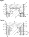
- a precision forging device and a precision forging product in accordance with a third embodiment will now be described with reference to Figs. 13A to 13D , 14A , and 14B.
- the metal material 10 of the present embodiment prior to working includes the circumferential wall 14, which has the form of a cylindrical wall in the same manner as the first embodiment, a top wall 15, which closes the opening at one end of the circumferential wall 14, and an outwardly directed flange 17A, which is coupled integrally with the outer circumferential of the other end of the circumferential wall 14 and extended outward in the radial direction.
- the circumferential wall 14 extends in the first direction that is an axial direction.
- the flange 17A is flat and extends in a direction intersecting the axial direction, that is, in the radial direction.
- the top wall 15 is flat and extends in a direction intersecting the axial direction, that is, in the radial direction, but does not have to be flat.
- the top wall 15 may include an outer surface that is a concave surface, which is part of a spherical surface, and an inner surface that is a convex surface, which is part of a spherical surface.
- the top wall 15 may include an outer surface that is a convex surface, which is part of a spherical surface, and an inner surface that is a concave surface, which is part of a spherical surface.
- the inner and outer surfaces of the top wall 15 may both be a concave surface, which is part of a spherical surface, or a convex surface, which is part of a spherical surface. That is, there is no limit to the plan view shape and cross-sectional shape of the top wall 15.
- the precision forging device 50 used in the present embodiment will now be described.
- the precision forging device 50 includes the die 20, which has the die cavity 22, the punch 30, the stopper 24, a knockout 25, and the counter punch 40.
- the cross-sectional shape of the die cavity 22 is circular but not limited and may have other shapes.
- the cross-sectional shape of the die cavity 22 may be in conformance but does not have to be in conformance with the contour shape of the flange 17A.
- the flange 17A does not conform to the wall surface of the die cavity 22, it may be shaped so that at least a part comes into plane contact.
- the flange 17A is shaped in conformance to entirely come into plane contact with the wall surface of the die cavity 22.
- the punch 30 has the form of a cylindrical tube.
- the outer diameter of the punch 30 is equal to the inner diameter of the die cavity 22, and the cutting blade 32 is formed on the inner circumferential edge of the punch 30.
- the cutting blade 32 is formed to move continuous chips, which are produced when the circumferential wall 14 of the metal material 10 is cut, toward the radially outer side.
- the cutting blade 32 of the punch 30, which has an inner diameter that is larger than the inner diameter of the circumferential wall 14 and smaller than the outer diameter of the circumferential wall 14, is arranged coaxially with the die cavity 22. That is, the cutting blade 32 is formed inward from the side (outer circumferential surface) of the flange 17A that comes into plane contact with the wall surface of the die cavity 22.
- the punch 30 is arranged opposed toward part of the circumferential wall 14 thickness-wise and the flange 17A.
- the cutting blade 32 is arranged so as to allow shear deformation to occur in part of the circumferential wall 14 thickness-wise, that is, the outer circumferential region of the circumferential wall 14 located radially outward from the inner circumferential edge of the cutting blade 32.
- the stopper 24, which is arranged coaxially with the die cavity 22, has a transverse cross section that is circular to conform to the contour shape of the top wall 15 of the metal material 10, as shown in Fig. 14A .
- the stopper 24 is arranged to contact the outer surface of the top wall 15 when shear deformation occurs in the outer circumferential region of the circumferential wall 14 located radially outward from the cutting blade 32.
- the stopper 24 only has to hold the metal material 10 when the metal material 10 is cut.
- the stopper 24 does not have to conform to the other shape of the top wall 15 and may be shorter in length in the radial direction than the top wall 15 or have a non-circular shape.
- the knockout 25 includes a main body portion 25a having a circular cross section and a fitting portion 25b having a circular cross section with a smaller diameter than the main body portion 25a.
- the fitting portion 25b has the same diameter as the diameter of the inner hollow of the circumferential wall 14 and can be freely fitted into and removed from the circumferential wall 14.
- the fitting portion 25b may have a cross-sectional shape conforming to the cross-sectional shape of the inner surface of the circumferential wall 14.
- An engagement step 25c is formed between the main body portion 25a and the fitting portion 25b.
- the engagement step 25c is engaged with the end surface of the circumferential wall 14 when the fitting portion 25b is fitted into the circumferential wall 14.
- the main body portion 25a has an outer diameter set to be proximate to the cutting blade 32.
- the counter punch 40 opposed toward the punch 30 has the form of a cylindrical tube and is arranged to contact the flange 17A when entering the open space surrounded by the circumferential wall 14 of the metal material 10 and the wall surface of the die cavity 22. Further, an air cylinder or the like (not shown) applies back pressure to the counter punch 40 so that the counter punch 40 constantly presses the flange 17A.
- the punch 30 corresponds to the first punch, and the counter punch 40 corresponds to the second punch.
- the counter punch 40 is not an essential element and may be omitted.
- the metal material 10 which includes the flange 17A and the circumferential wall 14 is arranged in the die cavity 22 of the die 20 of the precision forging device 50 so that the outer surface of the top wall 15 comes into contact with the stopper 24.
- the circumferential wall 14 is arranged in the die cavity 22 so as to extend in the punch moving direction
- the flange 17A is arranged so as to extend in a direction intersecting the punch moving direction.
- the punch moving direction coincides with the axial direction of the circumferential wall 14.
- the outer circumferential surface of the flange 17A is in plane contact with the wall surface of the die cavity 22.
- the punch 30 is moved toward the flange 17A to press and cut the circumferential wall 14 with the cutting blade 32.
- the metal material 10 remains held by the stopper 24 in the moving direction of the punch 30.
- the moving amount of the punch 30 from when the punch 30 initially contacts the flange 17A is in a range from greater than or equal to the thickness of the flange 17A and less than the height h of the circumferential wall 14 (refer to Fig. 14A ).
- Fig. 14B is a diagram illustrating a state when cutting has ended where the flange 17B becomes flush with the outer surface of the top wall 15.
- the metal flow W extends from the portion denoted by reference character "B” to the portion demoted by reference character "A.”
- the portion denoted by reference character “B” is where the joint line B was located until just before the flange 17B became flush with the outer surface of the top wall 15. Even when the flange 17B becomes flush with the outer surface of the top wall 15, the joint line B will be left as a trace.
- the surface of the flange 17B at the side where the joint line A is located corresponds to a first surface
- the surface of the flange 17B at the side opposite to the first surface corresponds to a second surface.
- the flange 17A, 17B is constrained by the die 20 so that the dimensions do not change in the direction intersecting the moving direction of the punch 30, as viewed in Figs. 14A and 14B .
- the material (chips) is compressed and moved toward the node to increase the thickness of the node.
- the back pressure Fb applied to the counter punch 40 is much smaller than the pushing force F of the punch 30, that is, Fb ⁇ F is satisfied.
- the counter punch 40 is moved backward against the urging force (back pressure) applied by the air cylinder or the like (not shown).
- the stopper 24 and the counter punch 40 are separated from the die 20. Then, the knockout 25 is moved toward the stopper 24 to remove the metal material 10 from the die 20.
- the pre-working flange 17A which is located at one end of the circumferential wall 14, is moved to the other end of the circumferential wall 14 and becomes the flange 17B.
- the thickness of the post-working flange 17B is greater than the thickness of the pre-working flange 17A, and the circumferential wall 14 has a post-working thickness K 1 that is less than the pre-working thickness Ko.
- the precision forging product in accordance with the present embodiment can be obtained with a small tool pressure. More specifically, the precision forging product of the present embodiment does not require a massive tool pressure during precision forging. Further, chips do not have to be separated during cutting and can be used as part of the precision forging product. Since a massive tool pressure is not required, the precision forging product can be a hollow component formed from high-strength material having large dimensions and a complicated cross-sectional shape.
- the precision forging in accordance with the present embodiment includes the circumferential wall 14, which serves as a wall portion and extends circumferentially, and the outwardly directed flange 17B, which is formed on the outer surface of the circumferential wall 14.
- the precision forging product flange has advantage (10).
- the metal material 10 of the present embodiment prior to working includes an inner tube 60 and an outer tube 62 that are arranged coaxially so as to form a duplex tube.
- One end of the inner tube 60 and one end of the outer tube 62 are coupled integrally by a bottom portion 64A.
- a ring-shaped groove 63 extends between the inner tube 60 and the outer tube 62.
- the inner tube 60 which corresponds to a circumferential wall and a wall portion, has the form of a cylindrical tube and extends in a first direction that is an axial direction.
- the outer tube 62 which has the form of a cylindrical tube, has an outer diameter that is equal to an inner diameter of the die cavity 22 of the die 20 of the precision forging device.
- the bottom portion 64A is flat and extends in a direction intersecting the axial direction, that is, in the radial direction, but does not have to be flat.
- the inner tube 60 and the outer tube 62 have circular cross sections but do not have to be circular and may be shaped differently.
- the precision forging device 50 includes the die 20, which has the die cavity 22, the punch 30, the stopper 24, and the counter punch 40.
- the die cavity 22 has a circular cross section but is not limited to such a shape and only needs to conform to part of the contour shape of the outer tube 62.
- the stopper 24 is arranged coaxially with the die cavity 22 and fixed by a fixing member (not shown). As shown in Fig. 16A , the stopper 24 includes a distal end that is fitted to the inner tube 60 of the metal material 10 and a step 24a that comes into contact with the end surface of the inner tube 60.
- the counter punch 40 which is opposed toward the punch 30, has the form of a cylindrical tube.
- the counter punch 40 is fitted in the groove 63 between the inner tube 60 and the outer tube 62 of the metal material 10 and arranged to contact the bottom portion 64A.
- An air cylinder or the like (not shown) applies back pressure to the counter punch 40 so that the bottom portion 64A is constantly pressed.
- the punch 30 corresponds to the first punch, and the counter punch 40 corresponds to the second punch.
- the counter punch 40 may be omitted.
- the metal material 10 is arranged in the die cavity 22 of the die 20 of the precision forging device 50, and the stopper 24 is fitted in the inner tube 60 so that the step 24a comes into contact with the inner tube 60.
- the inner tube 60 is arranged in the die cavity 22 so as to extend in the punch moving direction
- the bottom portion 64A is arranged so as to extend in a direction intersecting the punch moving direction.
- the punch moving direction coincides with the axial direction of the inner tube 60.
- the outer circumferential surface of the bottom portion 64A that is, the outer circumferential surface of the outer tube 62, is in a state in plane contact with the wall surface of the die cavity 22.
- the punch 30 is arranged in the die cavity 22 so as to be opposed toward the bottom portion 64A and part of the inner tube 60 thickness-wise.
- the part of the inner tube 60 thickness-wise that is opposed toward the punch 30 is an outer circumferential region of the inner tube 60 located radially outward from the inner circumferential edge of the cutting blade 32.
- the punch 30 is moved toward the bottom portion 64A to press and cut the inner tube 60 with the cutting blade 32.
- the metal material 10 remains held by the stopper 24 in the moving direction of the punch 30.
- the movement amount of the punch 30 from where the punch 30 initially comes into contact with the bottom portion 64A is in a range that is greater than or equal to the thickness of the bottom portion 64A and less than the height of the inner tube 60.
- the reference character 64A denotes the bottom portion prior to working, and the reference character 64B denotes the bottom portion during and subsequent to working.
- the bottom portion 64A corresponds to a pre-working projecting wall.
- the bottom portion 64B corresponds to a post-working projecting wall.
- the sheared material (chips) cut out by the cutting blade 32 enters the bottom portion 64A between the punch 30 and the counter punch 40 (i.e., node) and forms a metal flow W between the joint line A and the joint line B, which are shown in Fig. 16A .
- Fig. 16B is a diagram illustrating a state when cutting has ended. As shown in Fig. 16B , the metal flow W extends from the portion in the first surface denoted by reference character "B" to the portion in the second surface denoted by reference character "A.”
- the bottom portion 64A, 64B is constrained by the die 20 so that the dimensions do not change in a direction intersecting the moving direction of the punch 30, as shown in Figs. 16A and 16B .
- the material (chips) is compressed and moved toward the node to increase the thickness of the node.
- the back pressure Fb applied to the counter punch 40 is much smaller than the pushing force F of the punch 30, that is, Fb ⁇ F is satisfied.
- the counter punch 40 moves backward against the urging force (back pressure) applied by the air cylinder or the like (not shown).
- the pre-working bottom portion 64A which is located at one end of the inner tube 60, is moved toward the other end of the inner tube 60 and becomes the bottom portion 64B.
- the thickness of the post-working bottom portion 64B is greater than the thickness of the pre-working bottom portion 64A, and the inner tube 60 has a post-working thickness K 1 that is less than the pre-working thickness Ko.
- the fourth embodiment has the same advantages as the third embodiment.
- the metal material 10 of the present embodiment prior to working includes the circumferential wall 14, which has the form of a cylindrical tube in the same manner as the first embodiment, and the bottom portion 12A, which is coupled integrally with the lower part of the circumferential wall 14.
- the precision forging device 50 used in the present embodiment differs from the precision forging device 50 described in the first embodiment in the shape of the cutting blade 32.
- the working end surface 31 of the punch 30 is flat, and the cutting blade 32, which is circular, is formed along the entire circumference of the working end surface 31 in a plan view of the punch 30.
- the working end surface 31 of the punch 30 is flat, and the cutting blade 32 formed along the entire circumference of the working end surface 31 includes recesses and projections that are arranged alternately in the circumferential direction.
- the structure is the same as the first embodiment.
- the cutting blade 32 does not have to be shaped to include the recesses and projections that are alternately arranged in the circumferential direction and may have any shape.
- the precision forging method according to the fifth embodiment is the same as the first embodiment and thus will not be described in detail.
- the first step is shown in Fig. 1A
- the second step is shown in Figs. 1B and 1C .
- Fig. 17C is a perspective view of the precision forging product subsequent to working
- Fig. 17D is a vertical, cross-sectional view of the precision forging product subsequent to working.
- the worked side of the inner circumferential surface in the circumferential wall 14 of the metal material 10 includes projections 14a and recesses 14b that are alternately arranged in the circumferential direction because of the cutting blade 32 of the punch 30.
- the thickness of the post-working bottom portion 12B is greater than the thickness of the pre-working bottom portion 12A, and the portion of the circumferential wall 14 subject to cutting has a post-working thickness K 1 that is less than the pre-working thickness Ko.
- the metal material 10 of the present embodiment prior to working includes the circumferential wall 14, which has the form of a cylindrical tube in the same manner as the first embodiment, and the bottom portion 12A, which is coupled integrally with the lower part of the circumferential wall 14.
- the bottom portion 12A is entirely flat.
- the central region of the bottom portion 12A is projected in the direction in which the circumferential wall 14 extends and defines a projected portion 19 that is a tubular body including a top wall as viewed in Fig. 18B .
- the projected portion 19 has a circular cross section and is arranged coaxially with the circumferential wall 14.
- a circular ring-shaped groove 19a extends between the projected portion 19 and the circumferential wall 14.
- the precision forging device 50 used in the present embodiment is similar to the precision forging device 50 described in the first embodiment and thus will not be described below.
- Fig. 18C is a perspective view of the precision forging product subsequent to working
- Fig. 18D is a vertical, cross-sectional view of the precision forging product subsequent to working.
- the bottom portion 12A which is located at one end of the circumferential wall 14 is moved toward the other end of the circumferential wall 14 and becomes the bottom portion 12B.
- the thickness of the post-working bottom portion 12B is greater than the thickness of the pre-working bottom portion 12A, and the portion of the circumferential wall 14 subject to cutting has a post-working thickness K 1 that is less than the pre-working thickness Ko.
- the sixth embodiment has the same advantages as the first embodiment.
- a precision forging device and a precision forging product in accordance with a seventh embodiment will now be described with reference to Figs. 19A to 19B, 20A, and 20B .
- the metal material 10 has an L-shaped cross section and includes a wall portion 114, which has the form of a quadrangular plate, and a pre-working projecting wall 112A, which has the form of a quadrangular plate and is coupled integrally to the lower part of the wall portion 114.
- the pre-working projecting wall 112A extends from the wall portion 114 in an orthogonal direction that is a direction intersecting the height-wise direction of the wall portion 114.
- the wall portion 114 corresponds to a flat wall portion.
- the height-wise direction corresponds to the first direction.
- the orthogonal direction which is a direction intersecting the height-wise direction, corresponds to the second direction.
- the reference character "112A" denotes the projecting wall prior to working
- the reference character “112B" denotes the projecting wall during and subsequent to working.
- the precision forging device 50 used in the present embodiment will now be described.
- the precision forging device 50 includes the die 20, which has the die cavity 22, the punch 30, the stopper 24, and the counter punch 40.
- the die cavity 22 has a transverse cross section having rectangular shape, that is, a quadrangular shape, to allow for fitting of the pre-working projecting wall 112A.
- the die cavity 22 includes two wall surfaces 22a and 22b that are opposed toward each other and correspond to the long sides of the rectangular transverse cross section.
- the first wall surface 22a is in contact with one side of the punch 32 and one side of the counter punch 40, and the second wall surface 22b is spaced apart from the other side of the punch 32 and the other side of the counter punch 40.
- the stopper 24 has the form of a polygonal pillar and is fixed to the die 20 in contact with the wall portion 114.
- the stopper 24 may be an engagement step formed integrally with the die 20.
- the punch 30 has the form of a plate.
- the working end surface of the punch 30 is flat, and the cutting blade 32 is formed on the edge of the working end surface opposed toward the second wall surface 22b of the die cavity 22.
- the cutting blade 32 extends in a direction perpendicular to the plane of the drawing.
- the cutting blade 32 is spaced apart by the gap S from the second wall surface 22b of the die cavity 22.
- the cutting blade 32 is formed to move continuous chips, which are produced when the wall portion 114 of the metal material 10 is cut, toward the wall surface 22a.
- the counter punch 40 which is opposed toward the punch 30, is arranged in the open space surrounded by the wall portion 114 of the metal material 10, the pre-working projecting wall 112A, the first wall surface 22a, and the like.
- An air cylinder or the like applies back pressure to the counter punch 40 so that the counter punch 40 constantly presses the projecting wall 112A.
- the counter punch 40 may be omitted.
- the metal material 10 which includes the pre-working projecting wall 112A and the wall portion 114, is arranged in the die cavity 22 of the die 20 so that the wall portion 114 comes into contact with the stopper 24.
- the wall portion 114 is arranged in the die cavity 22 so as to extend in the punch moving direction
- the pre-working projecting wall 112A is arranged so as to extend in a direction intersecting the punch moving direction.
- the punch moving direction coincides with the height-wise direction of the wall portion 114.
- the end surface of the pre-working projecting wall 112A is in plane contact with the first wall surface 22a of the die cavity 22.
- the punch 30 is arranged in the die cavity 22 so as to be opposed toward the pre-working projecting wall 112A and part of the wall portion 114 thickness-wise.
- the punch 30 is moved toward the pre-working projecting wall 112A to press and cut the wall portion 114 with the cutting blade 32.
- the metal material 10 remains held by the stopper 24 in the moving direction of the punch 30.
- the movement amount of the punch 30 from where the punch 30 initially comes into contact with the pre-working projecting wall 112A is in a range that is less than the height of the wall portion 114.
- the punch 30 presses the pre-working projecting wall 112A (112B) and cuts part of the wall portion 114 thickness-wise with the cutting blade 32
- shear deformation caused by the cutting blade 32 occurs between the joint line A of the projecting wall 112A (112B), which comes into contact with the cutting blade 32 of the punch 30, and the joint line B, which is located between the projecting wall 112A (112B) and the wall portion 114.
- the cutting blade 32 extends in a direction perpendicular to the plane of the drawing.
- the joint lines A and B of the present embodiment are straight lines.
- the sheared material (chips) cut out by the cutting blade 32 enters the projecting wall 112A (112B) (i.e., node) between the punch 30 and the counter punch 40 and forms a metal flow W between the joint line A and the joint line B, as shown in Fig. 20B .
- the surface of the projecting wall 112A (112B) where the joint line B is located corresponds to a first surface
- the surface of the projecting wall 112A (112B) at the side opposite to the first surface corresponds to a second surface.
- the metal flow W extends from the portion in the first surface denoted by reference character "B" to the portion of second surface denoted by reference character "A.”
- the pre-working projecting wall 112A (post-working projecting wall 112B) is constrained by the die 20 so that the dimensions do not change in a direction intersecting the moving direction of the punch 30, as shown in Figs. 20A and 20B .
- the material (chips) is compressed and moved toward the node to increase the thickness of the node.
- the back pressure Fb applied to the counter punch 40 is much smaller than the pushing force F of the punch 30, that is, Fb ⁇ F is satisfied.
- the counter punch 40 is moved backward against the urging force (back pressure) applied by the air cylinder or the like (not shown).
- the pre-working projecting wall 112A which is located at one end of the wall portion 114, is moved toward the other end of the wall portion 114, and becomes the projecting wall 112B.
- the thickness of the post-working projecting wall 112B is less than the thickness of the pre-working projecting wall 112A.
- the wall portion 114 has the form of a flat plate but may be bent in a transverse cross section that is orthogonal to the first direction.
- the cutting blade 32 of the punch 30 is shaped in conformance with the bend in the wall portion 114.
- a precision forging device and a precision forging product in accordance with an eighth embodiment will now be described with reference to Figs. 21A, 21B , 22A, and 22B .
- the metal material 10 of the present embodiment prior to working includes a semicircular wall portion 114 and a semicircular flange 120A extending radially and coupled integrally to the outer circumferential surface of the basal end of the wall portion 114.
- the flange 120A extends in the radial direction from the wall portion 114 in a direction intersecting the height-wise direction of the wall portion 114.
- the flange 120A corresponds to an outwardly directed flange.
- the wall portion 114 corresponds to a curved wall portion.
- the wall portion 114 is semicircular in a transverse cross section but does not have to be semicircular and may be shaped to have a different arcuate shape, such as the shape of the alphabet C, or have a shape defined by a radius of curvature varied in the circumferential direction.
- the height-wise direction of the wall portion 114 corresponds to the first direction.
- the radial direction corresponds to the second direction.
- the precision forging device 50 used in the present embodiment will now be described.
- the precision forging device 50 includes the die 20, which has the die cavity 22, the punch 30, the stopper 24, and the counter punch 40.
- the die cavity 22 includes the first wall surface 22a, which is a flat surface, and the second wall surface 22b, which is a concave surface, and is shaped to be semicircular in a transverse cross section so as to allow for fitting of the flange 120A.
- the punch 30 and the cutting blade 32 are semicircular, have a radius of curvature at the outer side that is the same as that of the second wall surface 22b, and are in plane contact with and slidable on the second wall surface 22b.
- the working end surface of the punch 30 has a length in the radial direction that is greater than the extending amount of the flange 120A from the wall portion 114 and less than the total of the extending amount of the flange 120A and the thickness of the wall portion 114 in the radial direction.
- the cutting blade 32 is formed along the entire inner edge of the working end surface of the punch 30.
- the counter punch 40 is semicircular, has a radius of curvature at the outer side that is the same as the second wall surface 22b, and is in plane contact with and slidable on the second wall surface 22b.
- the inner side of the counter punch 40 has the same radius of curvature as the outer surface of the wall portion 114 and is in plane contact with and slidable on the outer surface.
- the end surface of the counter punch 40 opposed toward the punch 30 is flat and contacts the flange 120A.
- the width of the counter punch 40 in the radial direction is equal to the extending length of the flange 120A from the wall portion 114.
- the engagement step 24f comes into contact with the wall portion 114.
- the side surface 24e of the main body portion 24h of the stopper 24 is in plane contact with and slidable relative to the counter punch 40. Further, the side surface 24e of the distal end portion 24g of the stopper 24 is in plane contact with the inner surface of the wall portion 114.
- the side surface 24d of the stopper 24 is entirely in plane contact with the first wall surface 22a.
- the precision forging method in accordance with the present embodiment and its advantages will not be described since they are similar to the precision forming method in accordance with the seventh embodiment and can be understood by interchanging "the pre-working projecting wall 112A" to "the flange 120A", “the projecting wall 112B subsequent to working” to “the flange 120B", “ Fig. 20” to “Fig. 22 “, “ Fig. 19” to “Fig. 21 “, “112A” to "120A”, and “112B” to “120B”.
- the flange 120A corresponds to the pre-working projecting wall.
- the cutting blade 32 of the punch 30 in the present embodiment is semicircular.
- the joint lines A and B are semicircular.
- the post-working flange 120B is located closer to the basal end than the central part of the wall portion 114 in the height-wise direction of the wall portion 114 but may be located at the upper end with respect to the height-wise direction of the wall portion 114, as shown in Fig. 21C .
- metal material 12A and 12B) bottom portion, 14) circumferential wall, 16) open space, 20) die, 22) die cavity, 24) stopper, 30) punch, 32) cutting blade, 40) counter punch, 50) precision forging device, A and B) joint line, W) metal flow
Landscapes
- Engineering & Computer Science (AREA)
- Mechanical Engineering (AREA)
- Forging (AREA)
Applications Claiming Priority (2)
| Application Number | Priority Date | Filing Date | Title |
|---|---|---|---|
| JP2019082093 | 2019-04-23 | ||
| PCT/JP2020/017392 WO2020218377A1 (fr) | 2019-04-23 | 2020-04-22 | Procédé de forgeage de précision, dispositif de forgeage de précision et produit de forgeage de précision |
Publications (2)
| Publication Number | Publication Date |
|---|---|
| EP3960328A1 true EP3960328A1 (fr) | 2022-03-02 |
| EP3960328A4 EP3960328A4 (fr) | 2023-01-18 |
Family
ID=72942559
Family Applications (1)
| Application Number | Title | Priority Date | Filing Date |
|---|---|---|---|
| EP20796108.7A Pending EP3960328A4 (fr) | 2019-04-23 | 2020-04-22 | Procédé de forgeage de précision, dispositif de forgeage de précision et produit de forgeage de précision |
Country Status (5)
| Country | Link |
|---|---|
| US (1) | US11925972B2 (fr) |
| EP (1) | EP3960328A4 (fr) |
| JP (1) | JP7062321B2 (fr) |
| CN (1) | CN113784808B (fr) |
| WO (1) | WO2020218377A1 (fr) |
Family Cites Families (28)
| Publication number | Priority date | Publication date | Assignee | Title |
|---|---|---|---|---|
| JPS56141935A (en) * | 1980-04-02 | 1981-11-05 | Toyota Motor Corp | Press die for manufacturing gear made of sheet metal |
| JPS61255740A (ja) * | 1985-05-10 | 1986-11-13 | Honda Motor Co Ltd | 歯車の精密鍛造方法 |
| JP2723344B2 (ja) * | 1990-06-26 | 1998-03-09 | 株式会社神戸製鋼所 | 精密鍛造法 |
| JP2534940B2 (ja) * | 1991-06-27 | 1996-09-18 | アイダエンジニアリング株式会社 | 環状溝の塑性加工方法 |
| JPH0538546A (ja) * | 1991-07-31 | 1993-02-19 | Musashi Seimitsu Ind Co Ltd | ボールジヨイント用ハウジング粗材の鍛造成形方法 |
| JPH07251235A (ja) * | 1992-04-02 | 1995-10-03 | San Shin Uu Chin Kon Chan Guu Fuun Yuu Shen Kon Shii | 押抜き鍛造法 |
| JPH07256385A (ja) * | 1994-03-17 | 1995-10-09 | Musashi Seimitsu Ind Co Ltd | ボールジョイント用ハウジングの鍛造成形方法 |
| JP3339363B2 (ja) * | 1996-11-25 | 2002-10-28 | トヨタ車体株式会社 | 半抜き成形方法およびこれに使用する冷間鍛造型 |
| JP3835941B2 (ja) * | 1998-11-12 | 2006-10-18 | アイシン機工株式会社 | 歯車粗材の製造方法 |
| JP2001047173A (ja) * | 1999-06-04 | 2001-02-20 | Toto Ltd | 型鍛造方法 |
| JP3990947B2 (ja) * | 2002-06-28 | 2007-10-17 | 小島プレス工業株式会社 | プレス加工による凹溝の形成方法及び装置 |
| JP2008036679A (ja) * | 2006-08-08 | 2008-02-21 | Nsk Ltd | 突出部付筒状部材の製造方法 |
| EP1894646B1 (fr) * | 2006-09-01 | 2012-10-17 | Feintool Intellectual Property AG | Procédé et dispositif de fabrication d'une denture sur un corps tridimensionnel déformé et estampé de haute précision |
| JP4840102B2 (ja) * | 2006-11-22 | 2011-12-21 | 日本精工株式会社 | 軌道輪部材の製造方法 |
| JP4984910B2 (ja) * | 2007-01-22 | 2012-07-25 | 日本精工株式会社 | 軌道輪部材の製造方法 |
| JP4900713B2 (ja) * | 2007-09-25 | 2012-03-21 | コンドーセイコー株式会社 | 冷間鍛造による平歯車の製造方法 |
| JP5412600B2 (ja) * | 2011-11-04 | 2014-02-12 | 三菱伸銅株式会社 | 銅合金熱間鍛造品 |
| JP5771231B2 (ja) * | 2013-03-11 | 2015-08-26 | 本田技研工業株式会社 | 鍛造加工方法及びその装置 |
| WO2014148357A1 (fr) * | 2013-03-18 | 2014-09-25 | シロキ工業株式会社 | Cliquet de mécanisme d'inclinaison, procédé pour fabriquer un cliquet de mécanisme d'inclinaison, et appareil pour fabriquer un cliquet de mécanisme d'inclinaison |
| JP6255205B2 (ja) * | 2013-10-10 | 2017-12-27 | 川重商事株式会社 | 鍛造成形装置 |
| DE102014116988A1 (de) * | 2013-11-28 | 2015-05-28 | Richard Bergner Verbindungstechnik Gmbh & Co. Kg | Verfahren zur Herstellung einer Montageeinheit |
| JP5833261B1 (ja) * | 2015-01-07 | 2015-12-16 | 株式会社関プレス | 金属端部断面外周の加工方法及び該加工方法によって得られる金属部品と他部材との接合方法 |
| US10857583B2 (en) | 2015-04-28 | 2020-12-08 | Nippon Steel Corporation | Press-working apparatus, press-working method, and press-molded product |
| WO2017006830A1 (fr) * | 2015-07-07 | 2017-01-12 | 日新製鋼株式会社 | Dispositif de moulage de saillie, procédé de moulage de saillie et article moulé |
| KR20170052919A (ko) * | 2015-11-05 | 2017-05-15 | 한호산업(주) | 플랜지를 구비한 치형단조품의 열간단조장치 |
| KR20170108486A (ko) * | 2016-03-18 | 2017-09-27 | 장준수 | 차량용 자동 변속기의 이너레이스, 오버드라이브 클러치 허브 및 그 제조방법 |
| CN106984755A (zh) * | 2017-03-27 | 2017-07-28 | 湖北三环锻造有限公司 | 轮毂单元挤冲孔锻造模具 |
| JP7173300B2 (ja) | 2019-04-03 | 2022-11-16 | 日本製鉄株式会社 | プレス成形品の製造方法 |
-
2020
- 2020-04-22 CN CN202080005041.3A patent/CN113784808B/zh active Active
- 2020-04-22 US US17/273,670 patent/US11925972B2/en active Active
- 2020-04-22 EP EP20796108.7A patent/EP3960328A4/fr active Pending
- 2020-04-22 JP JP2021516177A patent/JP7062321B2/ja active Active
- 2020-04-22 WO PCT/JP2020/017392 patent/WO2020218377A1/fr unknown
Also Published As
| Publication number | Publication date |
|---|---|
| JPWO2020218377A1 (ja) | 2021-11-04 |
| WO2020218377A1 (fr) | 2020-10-29 |
| CN113784808A (zh) | 2021-12-10 |
| US11925972B2 (en) | 2024-03-12 |
| EP3960328A4 (fr) | 2023-01-18 |
| US20210339306A1 (en) | 2021-11-04 |
| CN113784808B (zh) | 2024-03-01 |
| JP7062321B2 (ja) | 2022-05-06 |
Similar Documents
| Publication | Publication Date | Title |
|---|---|---|
| Choi et al. | Precision forging of spur gears with inside relief | |
| KR102000859B1 (ko) | 전단 가공 방법 | |
| US11614156B2 (en) | Metal sleeve and method for producing it | |
| CN113365752B (zh) | 冲压部件的制造方法以及坯料的制造方法 | |
| JP4869968B2 (ja) | 閉塞鍛造金型及び鍛造方法 | |
| EP3960328A1 (fr) | Procédé de forgeage de précision, dispositif de forgeage de précision et produit de forgeage de précision | |
| JP6253488B2 (ja) | 前方押出加工方法、中空部材の製造方法及び前方押出加工装置 | |
| Hassan et al. | Deep drawing of asymmetric cups through conical die without blank holder | |
| JP7188457B2 (ja) | 金属板のせん断加工方法及びプレス部品の製造方法 | |
| Tomov et al. | Modelling and description of the near-net-shape forging of cylindrical spur gears | |
| JP2006255778A (ja) | 座金とボルトの同時圧造方法 | |
| KR101473948B1 (ko) | 플랜지 구조체의 제조 방법 | |
| JP5157716B2 (ja) | 自在継手用ヨークの製造方法 | |
| US10239113B2 (en) | Net shaped forging for fluid ends and other work pieces | |
| JP2000140976A (ja) | 部品の製造方法 | |
| Killmann et al. | Local prestressing of cold forging tools by reinforcements with adapted interference | |
| JP2018158342A (ja) | 長円かしめカラーの製造方法 | |
| JP2005205498A (ja) | 円筒状部品の製造方法 | |
| Saffar et al. | On the effects of eccentricity in precision forging process | |
| JP3422941B2 (ja) | リング状部品の製造方法 | |
| JP3128208B2 (ja) | リング状部品の製造方法 | |
| Jasim et al. | An investigation of the shearing forces using blanked carbon steel sheets | |
| JPH0516931B2 (fr) | ||
| Schreiber et al. | Optimum blanking clearance choice method by an approach coupling experimental trials and simulations | |
| Do et al. | The Double-Sided Upsetting of the End Thickenings on Rod Blanks |
Legal Events
| Date | Code | Title | Description |
|---|---|---|---|
| STAA | Information on the status of an ep patent application or granted ep patent |
Free format text: STATUS: THE INTERNATIONAL PUBLICATION HAS BEEN MADE |
|
| STAA | Information on the status of an ep patent application or granted ep patent |
Free format text: STATUS: THE INTERNATIONAL PUBLICATION HAS BEEN MADE |
|
| PUAI | Public reference made under article 153(3) epc to a published international application that has entered the european phase |
Free format text: ORIGINAL CODE: 0009012 |
|
| STAA | Information on the status of an ep patent application or granted ep patent |
Free format text: STATUS: REQUEST FOR EXAMINATION WAS MADE |
|
| 17P | Request for examination filed |
Effective date: 20210309 |
|
| AK | Designated contracting states |
Kind code of ref document: A1 Designated state(s): AL AT BE BG CH CY CZ DE DK EE ES FI FR GB GR HR HU IE IS IT LI LT LU LV MC MK MT NL NO PL PT RO RS SE SI SK SM TR |
|
| DAV | Request for validation of the european patent (deleted) | ||
| DAX | Request for extension of the european patent (deleted) | ||
| A4 | Supplementary search report drawn up and despatched |
Effective date: 20221221 |
|
| RIC1 | Information provided on ipc code assigned before grant |
Ipc: B21J 5/02 20060101ALI20221215BHEP Ipc: B21K 21/08 20060101ALI20221215BHEP Ipc: B21J 13/02 20060101ALI20221215BHEP Ipc: B21J 5/06 20060101AFI20221215BHEP |
|
| STAA | Information on the status of an ep patent application or granted ep patent |
Free format text: STATUS: EXAMINATION IS IN PROGRESS |
|
| 17Q | First examination report despatched |
Effective date: 20230904 |