EP3956177B1 - Lastenträger - Google Patents
Lastenträger Download PDFInfo
- Publication number
- EP3956177B1 EP3956177B1 EP20712839.8A EP20712839A EP3956177B1 EP 3956177 B1 EP3956177 B1 EP 3956177B1 EP 20712839 A EP20712839 A EP 20712839A EP 3956177 B1 EP3956177 B1 EP 3956177B1
- Authority
- EP
- European Patent Office
- Prior art keywords
- support
- support arms
- plug
- load carrier
- load
- Prior art date
- Legal status (The legal status is an assumption and is not a legal conclusion. Google has not performed a legal analysis and makes no representation as to the accuracy of the status listed.)
- Active
Links
Images


Classifications
-
- B—PERFORMING OPERATIONS; TRANSPORTING
- B60—VEHICLES IN GENERAL
- B60R—VEHICLES, VEHICLE FITTINGS, OR VEHICLE PARTS, NOT OTHERWISE PROVIDED FOR
- B60R9/00—Supplementary fittings on vehicle exterior for carrying loads, e.g. luggage, sports gear or the like
- B60R9/08—Supplementary fittings on vehicle exterior for carrying loads, e.g. luggage, sports gear or the like specially adapted for sports gear
- B60R9/10—Supplementary fittings on vehicle exterior for carrying loads, e.g. luggage, sports gear or the like specially adapted for sports gear for cycles
-
- B—PERFORMING OPERATIONS; TRANSPORTING
- B60—VEHICLES IN GENERAL
- B60R—VEHICLES, VEHICLE FITTINGS, OR VEHICLE PARTS, NOT OTHERWISE PROVIDED FOR
- B60R9/00—Supplementary fittings on vehicle exterior for carrying loads, e.g. luggage, sports gear or the like
- B60R9/06—Supplementary fittings on vehicle exterior for carrying loads, e.g. luggage, sports gear or the like at vehicle front or rear
Definitions
- a load carrier which comprises two movable support arms arranged on the vehicle as a basic element for receiving a bicycle rack.
- the support arms can be moved and rotated in the direction of travel and are mounted on a cross member using swivel brackets and four-bar linkages.
- One of the support arms is also height-adjustable using a rotary-push joint or another four-bar linkage on the cross member.
- the cross member is arranged with the support arms lying openly behind a bumper and is mounted on the vehicle in a height-adjustable manner on an upright link guide that is fixed to the vehicle and is curved at the lower end. The cross member and the support arms thereby carry out a curved travel movement between the stowed position and a tilted position of use.
- the EP 1 972 501 A2 teaches a rear carrier that can be detachably inserted from below into a vehicle-mounted receiving sleeve using a single central pin and rotated through 180° into a hidden non-use position in the rear of the vehicle and thereby be moved axially in the receiving sleeve.
- the central receiving sleeve can accommodate a ball coupling neck in exchange for the rear carrier.
- the EP 2 033 845 B1 shows another load carrier. It has a frame-like support structure, the height of which can be pivotally adjusted about a horizontal axis by means of a spindle nut, the support arrangement being on the spindle nut is mounted so that it can move longitudinally in the axial direction of the vehicle and can therefore be pulled out from under the vehicle floor to take up the operating position.
- the support structure has at its free end two support arms that can be pivoted about a horizontal axis and into which the holding pins of a bicycle rack can be inserted at the front.
- the EP 2 657 051 A1 deals with a coupling arrangement for a rear carrier, which comprises two independently pivotable and displaceable coupling arms or the arrangement of two coupling arms on a common bearing part for their simultaneous actuation.
- the coupling arms are each arranged in an open position between the rear of the body and the rear bumper.
- the WO 03/039913 A1 shows another load carrier with swing-out support arms without height adjustment.
- the invention solves this problem with the features in the main claim.
- the claimed design of the load carrier with a common base part and the height-adjustable and pivotable mounting of the support arms as well as a housing and a lifting and pivoting device and pivot arms arranged therein has various advantages.
- the support arms can assume a raised position in the swung-in non-use position. They can be hidden on the vehicle. In particular, they can be located above an adjacent edge of the vehicle, for example the lower edge of the rear of the vehicle. condition. To assume the position of use, the support arms can be lowered and then swung out. During the lowering movement, the support arms can be lowered into a position below the edge of the vehicle and then swung out under the edge of the vehicle. In the swung-out position of use, the support arms protrude beyond the edge of the vehicle and enable the attachment and releasable attachment of a support part.
- the design of the base part with the housing and the lifting and pivoting device arranged therein has significant advantages in terms of the compact and space-saving design, the low construction and control costs and an encapsulated storage option for the support arms in the non-use position within the housing.
- the support arms can be supported on the housing in the swung-out position of use.
- the loaded load carrier offers a high load capacity, which can accommodate, for example, several heavier e-bikes, range extender batteries, gas bottles or other heavy loads. Further advantages include a favorable center of gravity, improved ground clearance, more comfort and ergonomics and better and safer attachment of the load. The construction and tax costs are reduced.
- the kinematics are improved, with the movements and axes of movement of the support arms being well defined and can be precisely controlled. The support arms can be moved back and forth more easily between the hidden non-use position on the vehicle and between the swung-out use position.
- a straight shape of the support arms is particularly advantageous for this.
- a possibly inclined position of the base part is favorable.
- the support arms can be extended In the operating position, protrude upwards at an angle and support the weight of a load carried on the load carrier.
- the inclined position also has a positive effect on ergonomics and ground clearance, especially in motorhomes or similar with a larger rear overhang.
- a normal alignment of the base part with horizontally aligned support arms is possible.
- Horizontal support arms enable a special docking technique.
- the two or more support arms are arranged together on the base part fixed to the vehicle.
- the several support arms are mounted together on the base part in a height-adjustable manner, in particular in a height-displaceable manner.
- the support arms are each pivoted about their own upright pivot axis.
- the support arms can be arranged at a mutual lateral distance, i.e. transversely to the longitudinal direction of the vehicle. They can be located in particular on the side edges or corner areas of the base part.
- An installation location of the base part with a short distance in front of the rear wall or the rear bumper of the vehicle is particularly favorable.
- the support arm or arms can thereby be moved into the position of use without hindrance on, in particular under, the rear of the vehicle. They can protrude sufficiently far back over the rear of the vehicle while maintaining a high level of stability.
- the preferably displaceable, in particular linear, height adjustment of the support arms can take place together via the base part.
- the support arms can be arranged accordingly on the base part.
- the support arms preferably carry out the pivoting movement individually. A movement and pivoting sequence can also be specified here.
- the support arms can each have their own pivot bearing and their own pivot drive.
- the support arms can each be pivoted about an upright axis and their height relative to the ground can be adjusted along the same or a parallel axis.
- the upright axes are preferably straight. When installed, they can have an inclination away from the adjacent edge of the vehicle. The support arms can thereby assume the aforementioned inclined position in the position of use. Alternatively, the upright axes can be oriented vertically.
- the common height adjustment on the base part can be done, for example, via a lifting bridge there.
- the lifting bridge can be moved up and down in a preferably linear manner using its own drive, in particular a lifting drive. Thanks to the straight shape of the support arms, only a small height or lifting distance is required. In the lower lifting position, the support arms can be swung out into the use position without any disruptive contours under the vehicle edge or the vehicle floor.
- the support arms can always be arranged at the same height vertically on the base part. In the swung-in non-use position, they can lie one behind the other and possibly against each other at the same height in the axial direction of the vehicle and can also be at the same height in the swung-out use position. This can be achieved in different ways.
- the upright pivot axes can, for example, have an offset in the axial direction of the vehicle.
- the support arms can have a conical shape in plan view and taper towards the free end of the arm, whereby they execute different swivel angles about their respective upright swivel axis.
- the support arms of the loaded load carrier can be protected from unfavorable environmental influences in the non-use position, in particular splash water, snow, falling rocks and the like can be reliably protected.
- the construction effort as well as the space requirement and the movement kinematics are particularly favorable with straight support arms.
- the upright pivot axis for the support arms and the support arm shape aligned transversely to this pivot axis also save space.
- the preferably linear lifting movement and the pivoting movement of the support arms can take place along and around said axis.
- the load carrier has the base part, which can be permanently mounted on a vehicle using a mounting fitting.
- the base part fixed to the vehicle is rigid and arranged in a fixed position on the vehicle.
- a trailer hitch can also be mounted on the base part and/or the mounting fitting. This can be done using a cross member to be attached to the vehicle.
- the base part can also be mounted on this.
- the load carrier can have a carrier part on which a load can be accommodated.
- the load carrier can also be sold with the base part without the carrier part.
- the carrier part is itself an independent product. It can be mounted on an existing base part and also changed. Furthermore, any number of different carrier parts can be present, which can be detachably connected to the base part.
- the loose support part can be releasably attached to the support arm or arms, in particular attached or attached.
- the support part connects and stabilizes the support arms in their position of use.
- the support part can be a, preferably bridge-like, support part that can be connected to the swung-out support arms, in particular a so-called support bridge, and a Have load-carrying devices.
- the supporting part can alternatively be designed differently. Below it is referred to as a supporting bridge, whereby the design features can also be transferred to other supporting part shapes.
- An auxiliary support for another load-carrying device can be mounted on the support bridge.
- the support bridge and, if applicable, the auxiliary support can be permanently or detachably connected to the load-carrying device.
- a fastener enables the exact positioning and fixation of the load-carrying device on the support bridge or on the auxiliary beam.
- connection between the swung out support arms and the support bridge can be done in any way. It can be a plug-in connection, a mere support or another connection.
- the support bridge can be attached to the base part in any suitable manner.
- the support bridge can be placed or plugged onto the support arms loosely from above and/or from the front with a cuff-like support part, for example, and fastened to the central region of the support arms.
- This can be done using a lock.
- This can ensure a secure fixation and coupling connection between the support bridge and the support arms of the base part.
- the locking can act in three or more spatial axes.
- the loose support part can be designed for and can carry heavy loads of, for example, 150 kg and more.
- These one or more loads that can be accommodated or accommodated on a carrier part can be designed differently, for example as a bicycle rack, container or the like.
- Particularly heavy loads can be carried by a range extender battery for an electric vehicle Gas bottles, for example for a mobile home, or a fuel tank can be formed.
- Such loads can also be formed by other objects or bulk materials, fluids or the like.
- the range extender battery, gas bottles, fuel tank or the like can be a mobile media storage, in particular energy storage, the medium of which can be used to supply a consumer in the vehicle, in particular a motor vehicle or trailer.
- a suitable and preferably detachable media connection can be present for this purpose. This can be detachably coupled, for example, to an adapted media connection on the base part or elsewhere, for example directly on the vehicle.
- a medium, for example electrical energy, gas, liquid fuel or the like, can be transmitted to the said consumer in the vehicle via the media connection.
- the consumer can be, for example, a vehicle's own energy storage device, such as a battery, fuel tank or the like, or a drive, in particular a motor, or a heater, a cooling system or the like.
- the media connection can be used to resupply the mobile media storage, e.g. recharging the range extender battery at a stationary charging station.
- the loose carrier part with the media storage enables the vehicle to be replenished quickly and easily by changing the media storage at a supply station.
- a plurality of media storage devices in particular energy storage devices, can be stored at the supply station. They can be reloaded or refilled here.
- the supply station can be set up at the vehicle owner's home, at a gas station, in a car dealership or the like.
- the loose support part can be particularly adapted to heavy loads. It can have an attached or attachable support means for support when removed and removed from the base part and the support arms.
- the suspension means can be adjustable. It can be disabled for driving.
- the support means can be formed, for example, by fold-out and/or possibly height-adjustable support feet. These can, for example, be movable on the surface by means of rollers or in another way.
- the height adjustment can be designed and carried out differently, for example manually or by a motor or fluid drive.
- the height adjustment of the suspension means allows adjustment to different and vehicle-specific support arm heights.
- the base part with swung out and horizontally directed support arms enables the support part to be easily docked and undocked, e.g. by a horizontal driving or sliding movement. This is particularly advantageous for the heavy loads mentioned. It is also advantageous to have a height-adjustable suspension element, which can hold the carrier part at the appropriate docking height relative to the swung-out support arms and, if necessary, also lower it for placement on the support arms. This also makes undocking easier. When docking and undocking, the support arms and the support parts on the carrier part can be brought into and out of engagement.
- the load carrier in question with the base part and the support arms that can be raised and lowered as well as the detachable carrier part is particularly suitable for the loads in question, in particular a media storage device, preferably a range extender battery.
- the load carrier for such heavy loads can have a base part with pivoting support arms without their height adjustment include and have a carrier part in the training mentioned.
- the load carrier can have a power supply and a plug connection for transmitting energy and/or signals between the support arm and the carrier part.
- the plug connection can be present individually and only assigned to a single support arm. Alternatively, several plug connections are possible, which can also be arranged on several support arms.
- the plug connection can be located in the area of the mechanical connection or fastening point between the relevant support arm and the support part.
- energy and preferably also signals can be transmitted to one or more consumers on the carrier part.
- These can be, for example, electrical energy and flashing signals or brake signals or other signals.
- the transmission can take place to rear lights on the carrier part, e.g. taillights, brake lights, turn signals, reversing lights or the like.
- Other consumers such as closures that can be operated electrically or with other energy, other lights or the like, can also be supplied on the carrier part.
- the plug connection has its own inventive significance. It can also be used with other load carriers for a vehicle, especially a motor vehicle.
- a load carrier can have a movable, in particular pivotable, support arm that can be arranged or arranged on the vehicle and a support part that can be detachably attached or is attached to the support arm, the load carrier preferably having a power supply and a has an individual plug connection for transmitting energy and/or signals between the support arm and the carrier part.
- the said transmission of energy and/or signals between a movable support arm and the carrier part has advantages for the safety and accessibility of the plug connection.
- the ease of use when attaching and detaching the carrier part to and from the one or more pivot arms can be improved.
- the connection, in particular cross-connection, of the support arms through the support part preferably takes place in the area of the free ends of the support arms.
- the plug connection can be arranged outside, in particular behind, the vehicle's outer contour. It can be distanced from the rear of the vehicle and brought closer to the operator. This makes it better and easier to access and see than with a plug connection that is stationary at the rear of the vehicle.
- the mechanical connection or attachment point between the support arm in question and the support part is also more accessible and visible.
- the support arms can protrude beyond the adjacent edge of the vehicle, in particular the rear of the vehicle, in the extended, in particular swung out, position of use. This has advantages for the convenient and safe attachment of the load carrier to the support arm or arms and also for closing the plug connection. To remove the carrier part, the plug connection can also be released again in a simple and easily accessible manner.
- the carrier part can have a support part for releasable attachment to the support arm. If there are several support arms, there can be several support parts. A design of the support part that allows a positive, preferably pluggable, attachment to the support arm is particularly favorable.
- the support part can, for example, have an elongated arm holder.
- the elongated arm receptacle can be designed like a sleeve or a peg, with the associated support arm having a corresponding peg-like or sleeve-like counter contour.
- the plug connection is preferably used to transmit electrical energy and electrical signals. However, it can also be used for other energy and/or signal transmission, e.g. inductive, optical, etc.
- the plug-in connection has two or more plug-in parts that can be detachably connected to one another, with a plug-in part being arranged on the support arm and a plug-in part on the carrier part, in particular on the associated support part.
- the plug-in parts can each be arranged on the front side of the support arm and the support part. They can also be aligned in the direction of insertion. This is particularly favorable for a support part with an elongated arm holder.
- the plug-in parts can each be arranged laterally on the support arm and on the support part, in particular on the associated support part. You can also have a frontal distance from the respective front end of the support arm and support part or support part.
- the plug-in connection can advantageously generally be designed to be used when attaching the carrier part to the support arm by a relative movement between the carrier part, in particular support part and support arm to be closed.
- This can be a guided relative movement that facilitates and secures the meeting of the plug-in parts when the plug-in connection is closed.
- the relative movement can be a translational and/or rotational movement.
- a translational, in particular linear, plug-in movement is particularly favorable. Arranging the plug-in parts at the front is also advantageous for this.
- the plug connection can be closed at the same time. This simplifies and facilitates the assembly and disassembly of a carrier part and also simplifies operation.
- the plug connection can be closed/opened automatically when fastening/loosening the carrier part. This means the operator cannot forget to close the plug connection for transmitting energy and/or signals.
- the plug-in parts of the plug-in connection can be designed and arranged in such a way that when the carrier part is mounted or fastened to the support arm, they are connected to one another and brought into mutual engagement by said relative movement between the carrier part, in particular the support part, and the support arm.
- the mutual engagement can be positive.
- One plug-in part can be designed, for example, as a plug with pins and the other plug-in part as a socket with hollow receptacles for the pins.
- the plug-in parts are preferably multi-pole.
- a plug-in part can be arranged in a resilient manner on a receptacle with a spring. Such an arrangement can be provided for one of the preferably two plug-in parts of the plug-in connection or for several, in particular both, plug-in parts.
- the springy evasion ability has advantages for securing the plug connection and the energy and signal transmission while driving and for compensating for carrier component movements.
- the plug connection is relieved by the resilient evasive ability and can, for example, follow swinging movements.
- the load carrier can have a movement-tolerant, in particular pivot-tolerant, line that is guided along the support arm and is connected to the power supply and a plug-in part of the plug-in connection.
- This line can be taken along during the movement, in particular the pivoting movement, of the support arm in question.
- the cable can be guided closely along the support arm. This secures and protects the line. It also prevents excessive cable slack and the risk of getting caught on obstacles while driving. In the non-use position, the cable can be hidden on the base part together with the relevant support arm.
- a line can also be laid on the carrier part from the plug-in part there to the one or more consumers, in particular a lamp carrier.
- the defined plug connection enables tight and secure cable routing on the support arm and on the support part.
- the energy supply of the load carrier can be connectable or connected to an energy source and/or a signal transmitter of the motor vehicle.
- the load carrier can alternatively or additionally have its own energy source, for example an electric battery and a solar cell.
- the transmission of signals from the motor vehicle to the carrier part can be wired or wireless, for example via radio, Bluetooth, infrared, etc.
- the transmission of energy and signals to the carrier part can take place jointly via the energy supply and the said lines or separately and in different ways.
- the energy supply to the load carrier can have one or more supply lines to one or more other consumers.
- This can be, for example, a socket holder or a socket of an additional trailer coupling, which is additionally and centrally arranged on the load carrier, e.g. on the cross member or on the base part.
- the support arm provided with a plug-in part can be adapted in an interference-proof manner. It can have an arm housing and an electrically insulating insert arranged therein with a plug-in part mounted on the front.
- the plug-in part is preferably designed as a socket, which is advantageous for protection against damage.
- the arm housing can be made of a mechanically resilient and environmentally resistant material, e.g. metal.
- the support arm preferably has a peg-like shape.
- the support part can have an elongated and sleeve-shaped arm receptacle in which a plug-in part is arranged recessed at the rear end. It is protected and hidden in the inner cavity of the arm holder. It can be designed as a plug.
- the arm holder surrounds and guides the pin-like support arm when inserted. It also facilitates and secures the engagement of the plug-in parts and the closing of the plug-in connection.
- the arm holder can be made of an electrically insulating material.
- the invention relates to a load carrier (1). It is used to hold a load or load (28,28').
- the load carrier (1) is intended for a vehicle (25), in particular a road vehicle, and can be attached here.
- the vehicle (25) can be designed, for example, as a motor vehicle, in particular a car, van or mobile home, or as a trailer.
- the vehicle (25) has a longitudinal axis or direction of travel (34).
- the load carrier (1) can in particular be a rear carrier.
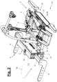
- the mounting situation at the rear of a vehicle (25) is indicated by dashed lines.
- the load carrier (1) has at least one base part (2) which can be arranged and fastened to the vehicle (25). In the installed position, the base part (2) is aligned transversely to the longitudinal axis (34) and is located at the rear of the vehicle (25). It is, for example, arranged on or in front of the rear wall and preferably largely hidden.
- the load carrier (1) can have a mounting fitting (6) for preferably stationary mounting of the base part (2) on the vehicle (25).
- the mounting fitting (6) can, for example, be available in the variants of Figures 1 to 9 have stub-like support arms (6') directed transversely to the vehicle's longitudinal axis (34). These can be attached to the base part (2) on both sides. They can each have a mounting flange (6") or the like at the free ends for attachment to a chassis or to the body of the vehicle (25).
- the mounting fitting (6) has a cross member (36) that extends across the width of the vehicle and on which the base part (2) can be mounted in a suitable manner, for example hanging. At the ends of the cross member (36). Mounting flanges (6") or the like can be arranged for fastening on the vehicle.
- a trailer hitch (35) and a socket holder (35') or a socket can also be mounted centrally on the cross member (36).
- the trailer coupling (35) can be designed to be removable or movable, in particular pivotable.
- the receiving part of a removable, in particular pluggable, trailer coupling (35) can be attached to the cross member (36).
- the removable or movable trailer coupling (35) does not interfere with the handling and load operation of the load carrier (1).
- the mounting fitting (6) in particular the cross member (36), can alternatively already be present on the vehicle (25).
- the load carrier (1) can also have a carrier part (3,3'). This can be detachably connected to the base part (2). It can be removed and changed if necessary.
- the carrier part (3,3') can be designed differently. It is used to hold a load or load (28,28').
- the carrier part (3.3') has one or more load-carrying devices (5.5'). These can be adapted to a load or load (28,28').
- the carrier part (3) shown is designed to hold a single load (28), for example one or more bicycles.
- Another load (28') can be, for example, an open or closed container or box.
- Support part (3') shown can accommodate several, for example two, identical or different loads (28, 28'). These can be, for example, bicycles and an open or closed container or box.
- the loads (28, 28') can be arranged one behind the other in the direction of travel (34).
- other training variants are possible.
- the load carrier (1) can be designed as an ensemble consisting of a base part (2) and one or more identical or different carrier parts (3, 3').
- the respective carrier part (3,3') is adapted to the base part (2).
- the carrier part (3,3') can be an independent product and a separate subject of the invention. It can be manufactured and sold separately from the base support (2).
- the support part (3) can have, for example, a bridge-like support part (4) and a load-carrying device (5).
- the supporting part (4) is described below as a supporting bridge. Alternatively, it can be designed differently.
- the support part (3') for several loads (28, 28') can also have the support bridge (4) with the load-carrying means (5) and also a frame-like auxiliary support (37) with another load-carrying means (5') for the additional load (28 ') exhibit.
- the auxiliary support (37) can be mounted firmly or releasably on the support part (3'), in particular on the support bridge (4).
- the auxiliary carrier (37) and its load-carrying device (5') increase the loading capacity of the load carrier (1) and can be assembled or dismantled if necessary.
- a load-carrying device (5) can be designed, for example, as a single or multiple bicycle holder.
- Another load-carrying device (5) can be designed, for example, as a container holder.
- the load-carrying means (5.5') can have a raised bracket that can be used to attach loads, for example for bicycle frames, and possibly as a handle for easier handling. This is also in Figures 19 to 21 shown.
- the supporting part in particular the supporting bridge (4), and the load-carrying device (5) can each be in one piece or in several parts.
- the support bridge (4) and the load-carrying device (5) can be designed separately and connected to one another in a fixed or detachable manner. They can also be designed as an integral structural unit.
- the auxiliary carrier (37) and its load-carrying means (5') can be designed accordingly.
- a detachable load-carrying device (5.5') can be positioned on the support bridge (4) or on the auxiliary support (37) using a fastening device (38) and can preferably be tensioned and fixed in a form-fitting manner.
- the manually operated fastening means (38) can interact with a pivoting bracket or handle, which can be folded from the upright position shown into a lying position. By rotating, clamping claws or the like can be operated for fastening and loosening. The folded position also allows for space-saving storage.
- the load carrier (1) preferably has several, in particular two, movable support arms (12, 13) which are intended for receiving and releasably connecting, in particular fastening, a carrier part (3, 3') to the base part (2).
- the carrier part (3,3') is supported in the mounted position by the support arms (12,13). It can rest loosely or guided on the support arms (12, 13) and can be releasably attached to the base part (2) in any way.
- the support part (3,3') can be releasably attached to the support arms (12,13) or elsewhere on the base part (2).
- the support arms (12, 13) are arranged together on the base part (2). They can be part of the base part (2).
- the support arms (12, 13) are mounted on the base part (2) in a height-adjustable manner and are also each its own upright axle (15) is pivotably mounted.
- the height-adjustable arrangement can be height-adjustable.
- the support arms (12, 13) can be adjusted together in height, in particular moved. They can be arranged accordingly on the base part (2).
- the support arms (12, 13) are arranged to be height-adjustable, preferably linearly height-displaceable, along the straight, upright axis (15).
- the upright axle (15) can be arranged obliquely in the installed position on the vehicle (25). You can do this from the adjacent edge of the vehicle, for example from the one in Figure 3 shown rear of the vehicle, away and inclined towards the front of the vehicle. Alternatively, one is in Figure 14 , 15 and 20 Vertical axis alignment shown is possible.
- the support arms (12, 13) are aligned transversely to the upright axis (15).
- the support arms (12, 13) can have parallel upright axes (15).
- the support arms (12, 13) and the upright axes (15) are arranged at a lateral distance on the base part (2). They are each located on a side edge area or corner area of the base part (2).
- the base part (2) extends transversely to the vehicle's longitudinal axis (34) and along the rear of the vehicle.
- the upright axes (15) and the support arms (12, 13) are spaced apart from each other in this direction.
- the support arms (12, 13) can always be arranged at the same vertical height.
- the upright axes (15) can be arranged at the same height as seen in the longitudinal direction (34) of the vehicle (25) or can have an axial offset (not shown). In the event of an axial offset, the support arms (12, 13) at the same height can be one behind the other in the longitudinal direction (34) in the swung-in position lie next to each other. When the support arms (12, 13) are pivoted in and out about their respective upright axis (15), a predetermined movement and pivoting sequence can exist.
- FIGs 22 to 25 show a variant of the support arm design, which also allows the support arms (12, 13) to rest against one another in the swung-in position.
- Figure 22 shows a front view of the base part (2) and Figure 23 a section in plan view according to section line XXIII - XXIII of Figure 22 .
- Figure 24 are a front view and in Figure 25 an associated sectional top view is shown.
- Figure 26 shows an aborted section along section line XXVI - XXVI of Figure 24 .
- Figure 27 is a detailed representation Figure 24 , which shows a section of a housing corner and a swung out and supported support arm (13).
- the upright axles (15) are arranged at the same height as seen in the longitudinal direction (34) of the vehicle (25).
- the support arms (12, 13) have a conical shape that tapers towards the free end of the arm, whereby they perform pivot angles ( ⁇ , ⁇ ) of different sizes about their respective upright axis (15) or pivot axis.
- the one support arm (12) lying at the rear in the swiveling position swivels, for example, through an angle ( ⁇ ) of less than 90°, for example approx. 87°.
- the other support arm (13) located at the front in the swivel-in position swivels for example, through an angle ( ⁇ ) of more than 90°, for example approx. 95°.
- the support arms (12) are between one in the Figures 1 to 8 as well as 24 and 25 shown use position (27) and one in Figure 9 , 22 and 23 shown non-use position (26) movable.
- the support arms (12, 13) are pivoted in and arranged hidden on the underside of the vehicle (25).
- the slot arms (12, 13) are swung out and protrude over the adjacent edge of the vehicle. This is for example in Figure 3 and 20 the rear of the vehicle.
- the pivoting movement into the use position (27) takes place according to Figure 3 and 20 below the edge of the vehicle, in particular below a rear bumper of the vehicle (25).
- the non-use position (26) the pivoted support arms (12, 13) are raised and can be hidden above the edge of the vehicle to increase the ground clearance.
- the lifting and lowering path along the upright axes (15) is dimensioned accordingly.
- the support arms (12, 13) can also be directed horizontally or obliquely upwards in a swung-out operating position (27).
- Figure 3 , 12 , 15 and 20 illustrate these alignments in the side view.
- the upright axis (15) has an inclined position when the support arm is aligned obliquely.
- the support arms (12, 13) have a straight orientation. Their shape can be designed to be load-friendly.
- the support arms (12, 13) can in particular according to Figure 8 have a conical shape in their longitudinal extent and in plan view, which tapers towards the free end of the arm.
- the support arms (12, 13) can be any suitable Have cross-sectional shape. They can, for example, be designed as U-profiles that are open at the bottom or as box profiles that are closed on the circumference.
- the base part (2) has a lifting and pivoting device (7) for the support arms (12, 13). With this, the support arms (12, 13) can carry out the kinematics described above.
- the base part (2) has a lockable housing (8).
- the lifting and pivoting device (7) is arranged in the housing (8).
- the support arms (12, 13) can be hidden in the housing (8) in the non-use position (26). In the use position (27), the support arms (12, 13) protrude outwards from the then opened housing (8).
- the lifting and swiveling device (7) contains several motor drives (11,16,17) for the height and swiveling adjustment of the support arms (12,13).
- the motor drives (11, 16, 17) can include, for example, electric motors, in particular geared motors.
- an energy supply (18) is arranged on the housing (8), which is connected to a suitable energy source, for example to the power supply of the vehicle (25), in particular its battery.
- a suitable energy source for example to the power supply of the vehicle (25), in particular its battery.
- the Figures 1 to 9 and 19 to 22 show this arrangement.
- the load carrier (1) also contains a plug connection (40) for transmitting energy and/or signals between the support arm (12, 13) and the carrier part (3, 3').
- the lifting and pivoting device (7) points according to Figure 8 a height-adjustable and driven lifting bridge (9), on which the support arms (12, 13) are arranged together and pivotally mounted by means of pivot bearings (14).
- the drives (16, 17), in particular swivel drives, of the support arms (12, 13) are also on the lifting bridge (9). arranged.
- the lifting bridge (9) extends horizontally, in particular horizontally, within the housing (8). It is raised and lowered by a motorized lifting drive (11). It is mounted so that it can move in parallel along the aforementioned axes (15) by means of a guide (10).
- the guide (10) can be formed by roller guides on the side housing walls. Alternatively or additionally, it can be formed, for example, by an upright rail guide running parallel to the axes (15) on a housing wall, for example on the front wall at the front in the direction of travel (34).
- Figure 8 , 23 and 25 shows this arrangement.
- a movable base part (8') of the housing (8) is arranged on the lifting bridge (9) and is spaced and held by means of holding rods (10'). It is moved when the height of the lifting bridge (9) and the support arms (12, 13) are adjusted.
- the lifting bridge (9) is lowered, the housing (8) is opened on the underside, with a free space being formed between the lowered base part (8') and the lower edge of the housing through which the support arms (12, 13) can be pulled out of the housing ( 8) can swing out into the use position (27).
- the Figures 3 to 8 and 12 to 18 illustrate this lowered position and the position of use (27). In the lifting position, the base part (8') tightly closes the open underside of the housing (8).
- the base part (8 ') rigidly on the housing (8) and to provide it with a slot-like opening through which the pivoted support arms (12, 13) are lowered out of the housing and then in the lowered position can be swung out into the use position (27) without hindrance.
- the pivoted support arms (12, 13) In the raised position, the pivoted support arms (12, 13) can be inserted into the correspondingly adapted opening in the Immerse the base part (8') and close it.
- the base part (2) has a support device (49) which serves to support the support arms (12, 13) in the swiveled out position of use (27).
- the support arms (12, 13) can be supported on the housing (8) and on the vehicle (25) via the mounting bracket (6).
- the support device (49) can support forces and moments introduced via the support arms (12, 13). The supporting effect can be released again when the pivoted non-use position (26) is assumed.
- the support device (49) can be designed differently.
- Figures 22 to 26 illustrate an example of an advantageous embodiment.
- the support device (49) has, for example, vertically acting support means (50, 51) and horizontally acting support means (52, 53) on the support arms (12, 13) and on the housing (8).
- the vertically acting support means (50,51) are arranged, for example, in the interior of the housing (8).
- the horizontally acting support means (52, 53) can be arranged on the outside.
- Figure 26 shows the support and engagement position of the support means (50,51,52,53).
- the one vertically acting support means (50) can, for example, be formed by a horizontal stop, in particular a fold, on the lower edge of the housing, which interacts with a support means (51) on the respective support arm (12, 13), which, for example, is a projecting and in Support position resting on the stop support nose is formed.
- the base part (8') can have a recess for tightly receiving the support means (50) in the closed position.
- the one horizontally acting support means (52) can be arranged on the outside of the housing wall, in particular in the corner area. It can, for example, be designed as a stiffening plate and placed on the housing wall.
- the other horizontally acting support means (53) can be designed, for example, as a raised stop lug on the top of the respective support arm (12, 13).
- the supporting means (52,53) act in the longitudinal direction (34). They can be brought into engagement and stop position when the support arms (12, 13) are swiveled out.
- the intervention can be form-fitting and, for example, also have a vertical effect. This can be achieved, for example, by a stepped shape of the stop surfaces of the support means (52, 53).
- the housing (8) is connected to the mounting fitting (6) in a suitable manner.
- the support arms (6') are attached to the side of the housing (8).
- the housing (8) is connected to the cross member (36) via retaining fittings. It can be done according to Figures 14 to 17 be arranged on the long side of the cross member (36) facing the front of the vehicle.
- the trailer coupling (35), if present, is mounted on the cross member (36) in the middle and in the longitudinal direction (34) behind the housing (8).
- Embodiments of the load carrier (1) shown can have the same design of the base part (2) with lifting and pivoting device (7), housing (8) and upright axes (15).
- the load carrier (1) has the aforementioned carrier part (3,3') for receiving a load or load (28,28'), which can be detachably connected to the base part (2). It can be supported on the support arms (12, 13). become. In the embodiments shown, it can also be releasably connected to the support arms (12, 13) and fixed to the support arms (12, 13) in the use position (27).
- the different support parts (3, 3') each have the mentioned support bridge (4) and a load-carrying device (5) for a load or load (28).
- This in Figures 10 to 18 The carrier part (3') shown additionally has an auxiliary carrier (37) and a further load-carrying device (5') for a load (28').
- the individual load-carrying device (5) is designed as a bicycle holder and the load (28) is designed as an arrangement of one or more, for example two, bicycles.
- the load-carrying device (5) can be designed differently.
- Figures 19 to 21 show a single load-carrying device (5) that is multifunctional and can either hold a container (28') or another load, such as bicycles.
- the further load-carrying device (5') shown is designed, for example, as a bicycle holder and the load (28') as an arrangement of one or more, for example two, bicycles.
- the load-carrying device (5) can also be designed either as a bicycle holder or as a container holder for a load (28) consisting of bicycles or a container.
- a load consisting of bicycles or a container.
- FIGs 10 to 13 For clarity, both design options for the load-carrying means (5) and the load (28) are shown in a common arrangement. In practice, only one load-carrying device (5) is usually used for the box or for the bicycles or for another load.
- a load-carrying device (5) e.g. the bicycle holder
- a second load-carrying device (5) e.g. a box holder
- the bicycle holder remains connected to the support bridge (4).
- the support bridge (4) present in both variants of the carrier part (3,3') is designed to be connected to the base part (2). It can be supported and attached to the base part (2).
- the support bridge (4) can be connected to the swung-out support arms (12, 13). It can rest on the support arms (12, 13) and in particular can be plugged on.
- the support bridge (4) connects the swung-out support arms (12, 13), which are preferably parallel in the use position (26), transversely to the longitudinal axis (34) and supports them mutually.
- Figures 1 to 5 and in Figures 10 to 18 Various embodiments of the support bridge (4) are shown.
- the support bridge (4) has two elongated support parts (19) on the edge, each of which can be detachably connected to a support arm (12, 13).
- the support parts (19) each have a straight orientation along the axis (34).
- the support part (19) can rest flat, preferably flat, on the respective support arm (12, 13) over a large part of its length. It can also encompass its support arm (12, 13) on one or more other sides.
- the support part (19) can, for example, be designed like a sleeve and can be placed on the respective support arm (12, 13) from above or pushed from the free front end onto the respective support arm (12, 13) in its longitudinal direction.
- the support part (19) has a guide means (20). This can ensure multi-axis upright and lateral guidance and support of the support part (19) on the associated support arm (12, 13).
- Figure 6 shows this arrangement in front view.
- the guide means (20) can engage in the U-shaped support arm (12, 13) from below. It can be designed to be low-friction and as a sliding aid for attaching to the front end of the support arm.
- the guide means (20) can be mounted on the side wall and on a bent edge or flange of the support part (19). In the other embodiments of Figures 10 to 18 A guide means (20) may be omitted or designed differently.
- the support bridge (4) also has a stiffener (21) which connects the support parts (19) to one another in the transverse direction and provides stiffening support.
- the stiffener (21) can, for example, according to Figures 1 to 5 be crosswise or in an X shape. In the other embodiments, the stiffener (21) is formed by several cross struts.
- the carrier part (3,3'), in particular the support bridge (4), has a releasable lock (22) for the fixing connection and coupling of the carrier part (3,3') to the base part (2).
- the releasable lock (22) serves for the fixing connection and Coupling the support part (3,3') with the support arms (12,13).
- the support means (19) can be used to loosely support and support the carrier part (3, 3'), in particular the support bridge (4), on the support arms.
- the lock (22) can be designed differently. In the exemplary embodiments shown, the lock engages the central region of the support arms (12, 13). Alternatively, an attack elsewhere is possible. A lock (22) can also exist, for example, between the housing (8) and the support bridge (4). In the various variants, the lock (22) preferably acts three-dimensionally. It offers a corresponding three-dimensional fixation.
- the lock (22) is arranged between the support bridge (4), in particular the stiffener (21), and the support arms (12, 13).
- the lock (22) has an operating part (29) arranged on the support bridge (4) or at another suitable location, which acts on one or more movable bolts (23) which are connected to one or more bolt receptacles (24) on the support arms ( 12,13) work together.
- the latch receptacles (24) can be arranged, for example, in the middle area of the support arms (12, 13).
- the latches (23) are moved by the operating element (29) and, in the latching position, engage positively in the respective latching receptacle (24).
- the latches (23) can be spring-loaded. They move transversely or obliquely to the longitudinal axis (34) and in opposite directions.
- the bolt receptacle (24) can be designed as a through opening or bore which approximately corresponds to the bolt dimensions and into which the bolt (23) is inserted in a form-fitting manner.
- the latch receptacle (24) has a fixing element (30) which is resiliently deformable and is located in a surrounding holder (32).
- the fixing element (30) deforms when acted upon by the associated latch (23) and thereby becomes clamped in the surrounding holder (32). This is formed in the respective support arm (12, 13).
- Figure 17 and 18 illustrate this training.
- the fixing element (30) can, for example, consist of a compressible shaped piece made of rubber, PU or another suitable material, in particular a polymer. It can, for example, have an opening (31), in particular a blind hole, aligned along the bolt (23).
- the bolt (23), which is advanced when the lock (22) is closed, can dip into this with its conical tip. It can compress and deform the fixing element (30) in all three translational spatial axes.
- the latch (23) reaches through a corresponding opening in the support part (19).
- the latch (23) and the fixing element (30) are mutually fixed in three dimensions and the fixing element (30) clamped in the holder (32) is fixed in three dimensions relative to the respective support arm (12, 13) and is guided in a form-fitting manner.
- the support part (3,3') can have a light support (33) at the rear end.
- a license plate holder can also be attached to this.
- the light support (33) can be arranged in a fixed or detachable manner at the rear end of the support bridge (4).
- the light holder (33) can also be designed to be foldable.
- the auxiliary support (37) with the load (28') can protrude backwards beyond the lamp support (33) in the axial direction (34).
- the load carrier (1) and its base part (2) as well as its connected carrier part (3,3') can be powered via the power supply (18).
- a line (39) can be laid from the housing (8) along a support arm (12, 13) to a socket (42), into which a plug (41) can be inserted when a support part (3, 3') is installed. This can be done automatically if necessary.
- the socket (42) can be arranged on the front side of a support arm (12, 13) and the plug part (41) on a support means (19). The arrangement can also be reversed.
- the aforementioned plug connection (40) is in Figures 26 to 36 shown in different embodiments.
- the plug connection (40) serves the aforementioned transmission of energy and/or signals between at least one support arm (12, 13) and the support part (3, 3'), in particular its support part (19).
- the plug connection (40) is located in the area of the mechanical connection point between the relevant support arm (12, 13) and the support part (19). In the exemplary embodiments shown, only one plug connection (40) is present and assigned to a support arm (13).
- the plug connection (40) is arranged outside the vehicle contour in the use position (27) of the extended or swung-out support arms (12, 13). It is preferably located at a distance behind the outer contour of the vehicle, in particular the rear of the vehicle.
- the support part (19) is designed for a positive and preferably pluggable attachment to the respective support arm (12, 13).
- the support part (19) has in the embodiment of Figures 28 to 36 each has an elongated arm holder (19").
- the arm holder (19") has a straight sleeve or tube shape and is attached to the peg-shaped support arm (12, 13).
- the arrangement can also be reversed, with the support arm (12, 13) having a tubular or sleeve shape and the arm receptacle (19") being designed like a peg.
- the plug connection (40) is preferably designed electrically. Alternatively, another connection and transmission option for energy and/or signals is possible.
- the plug connection (40) has two or more plug parts (41, 42) that can be detachably connected to one another. When connecting the plug-in parts (41, 42), energy and/or signals are transmitted electrically and conductively.
- the plug-in parts (41, 42) can interlock positively during the connection.
- a plug-in part (41) is arranged on the support arm (12, 13) and another plug-in part (42) to be connected is arranged on the support part (3, 3'), in particular on the support part (19).
- the plug-in parts (41, 42) are each designed to have multiple poles.
- one plug-in part (41) is designed as a plug and the other plug-in part (42) is designed as a socket.
- the plug (41) is sleeve-shaped Arm receptacle (19") is arranged.
- the socket (42) is located on the relevant support arm (12,13).
- the plug-in parts (41,42) are in the embodiments of Figures 28 to 36 each arranged on the front side of the arm holder (19") and on the support arm (12, 13) and aligned in the plug-in direction or arm direction.
- the plug connection (40) is designed to be resilient. At least on one of the plug-in parts (41, 42) to be connected is a receptacle (43) with a spring (44) for resilient evasive ability.
- the plug-in part (41), in particular the plug is arranged in a resiliently deflectable manner on the arm receptacle (19").
- the arm receptacle (19") is open at its end facing the base part (2) and has a transverse wall at its rear end locked.
- the plug-in part (41) has a widened base plate and, with its plug contacts protruding transversely from the base plate, protrudes through an opening in the transverse wall of the arm receptacle (19").
- the base plate remains outside the arm receptacle (19") and is one of two Guide pins formed receptacle (43).
- a spring (44) is mounted on the outside of each guide pin between the base plate and a widened pin end.
- the receptacle (43) or the guide pins are mounted on the transverse wall of the arm receptacle (19").
- the plug-in part (41) can slide with its base plate on the guide pins against spring force.
- the receptacle (43) can be used as a guide bushing or in another way be trained.
- the plug-in part (41) protruding into the hollow interior of the arm receptacle (19") can be connected there to the other plug-in part (42), in particular a socket, in particular plugged together in a form-fitting manner.
- the plug-in part (42) is located at the front end of the support arm (12 ,13).
- the support arm (12, 13) has an arm housing (45) and an insert (46) arranged therein, at the front end of which the plug-in part (42) is mounted.
- the insert (46) can consist of an electrically insulating material, for example plastic.
- the plug-in part (42) is attached to the front end of the insert (46).
- the attachment can be rigid or have axial movement in the direction of the arm.
- the front end of the insert (46) can be hollow.
- the insert (46) can have the above-described latch receptacle (24). There can be a suitable through opening on the inside of the arm housing (45).
- the support part (19), in particular the arm holder (19"), can also have a passage opening for the latch (23) on the latch side.
- the arm receptacle (19") can also consist of an electrically insulating material, in particular plastic. It can be designed in several parts and can, for example, according to Figure 36 a pipe part, preferably made of plastic, and an angled one Have fastening part.
- the support part (19) can also have, for example, a rail-like support means (19'), at the end of which the arm receptacle (19") facing the base part (2) is arranged and preferably guided in a form-fitting manner.
- the fastening part and the support means (19') can, for example made of metal and can surround the inserted pipe part on the circumference and back.
- the plug-in part (42) on the support arm (12, 13) is connected to the power supply (18) by a line (39), for example an electrical cable.
- a line (39) for example an electrical cable.
- the line (39) is guided along the support arm (12, 13). It is designed to be movement-tolerant, particularly pivot-tolerant. In the version shown, the line (39) is flexible.
- the plug-in part (41) on the support part (19) can also be connected to one or more consumers on the support part (3, 3'), in particular on the lamp support (33), via a line, not shown. This line can be firmly connected to the plug-in part (41).
- the plug-in part (41) as an adapter and to attach at least one plug to the line of the carrier part (3,3'), which is detachably connected to the adapter if necessary.
- the plug-in means (41) it is possible to include not only consumers on the lamp holder (33), but also any consumers on a load holder (5.5'), for example lights, electrically or otherwise operable closures or the like To supply energy and, if necessary, signals.
- Various lights, tail lights, brake lights, license plate lights, indicators, reversing lights or the like can be attached to the light adapter (33).
- Figure 37 and 38 show other variants of the design of a support arm (12, 13) of a support part (3, 3 ') and a plug connection (40).
- the support arm (13) shown is designed as a curved ball neck. It can be present individually or multiple times and can be movably arranged on said cross member (36) or base part (2). It can, for example, be moved, in particular pivoted, with a corresponding, possibly motor-driven, mechanism between a hidden non-use position and the extended use position (27) shown.
- the curved ball neck has a ball at the free end. This can correspond to a conventional coupling ball of a ball head coupling.
- the support part (19) of the carrier part (3,3') has a round socket (48) for connection to the ball.
- This can have the shape of a ball socket like a conventional trailer hitch.
- Figure 37 and 38 each show a plug connection (40) with two plug parts (41, 42) that can preferably be connected in a form-fitting manner. These are arranged laterally on the support arm (13) and on the support part (19). You can be at a distance from the front end of the support arm (13) and the support part (19).
- the line (29) is laid along the support arm (39) and is movement-tolerant, in particular pivot-tolerant. It is connected at the end to a power supply (18).
- the plug connection (40) can be closed automatically when the loose support part (3,3') is mechanically connected and fastened to the one or more plug arms (12,13).
- the side plug-in parts (41, 42) are aligned and arranged with respect to one another in such a way that they are automatically plugged together when the support part (19) is plugged vertically onto the support arm (13). and be connected.
- the plug-in parts (41,42) are aligned obliquely to the plug-in direction. They can be connected by a pivoting movement of the attached support part (19), marked with an arrow, this relative movement being guided via the contact between the ball and socket (48).
- a receptacle (43) and a suspension (44) can also be present for a resilient evasive ability of at least one plug-in part (41, 42).
- FIG 39 shows a further variant of the load carrier (1), which is designed for particularly heavy loads (28").
- a load (28") can, for example, be an in Figure 39 be the energy storage shown.
- this is designed as an electric range extender battery for an electric vehicle (25), which has an electric motor and a system battery or a system battery. These are referred to as consumers (56).
- the base part (2) can be designed in the manner described above and has two or more support arms (12, 13) which can be swung out into the position of use (27) about an upright axis (15).
- the pivot arms (12, 13) are arranged on the base part (2) so that they can be raised and lowered in the manner described above.
- the base part (2) can be designed in a different way, for example without or with a different lifting and lowering function.
- the carrier part (3") takes the load (28"). It can be designed in the manner described above and have a support bridge (4) with a stiffener (21) and with support parts (19). The support part (3") can be pushed onto the front of the swung-out support arms (12, 13) or attached from above.
- One Electrical plug connection (40) of the type described above can also be present.
- the load carrier (1) has a media connection (54) between the range extender battery (28") and at least one consumer (56).
- the media connection (54) is formed by a suitable electrical line. This can preferably be detached using a Media connection (55) can be connected to a line in the vehicle (25) leading to the consumer.
- the media connection can be formed from plug-in parts, one of which is on the media connection (54) and the other on the vehicle (25), in particular on the base part (2).
- the vehicle-side plug part can be arranged, for example, on the mounting fitting (6), in particular on the cross member (36).
- the range extender battery (28") can be permanently connected to the carrier part (3"). It can be arranged in a surrounding housing.
- Another media storage, in particular energy storage, can also be designed and arranged in a similar manner. This can be, for example, a gas tank, a fuel tank or the like.
- the media connection (54) and the media connection (55) are adapted accordingly.
- the support part (3") can have an attached or attachable support element (57).
- the support element (57) can be arranged on the underside of the support part (3"). It can be designed to be adjustable, in particular height-adjustable.
- the suspension element (57) can be removed or deactivated for driving operations.
- the support means (57) is formed by, for example, pluggable or pivotable support feet, which can have rollers on the underside for transporting the support part (3").
- a height adjustment can be realized, for example, by changing the foot length by means of a mechanical spindle or rack drive or the like with manual operation by a crank or by means of a drive, for example an electric motor or the like
- the support element (57) serves to support the carrier part (3") and the load (28") when removed and removed from the support arms (12, 13).
- the suspension element (57) relieves an operator and makes it easier to handle the carrier part (3") and the load (28"). It also enables easy docking and undocking of the carrier part (3") on and from the support arms (12, 13) by a relative travel movement between the vehicle (25) and the carrier part (3") positioned at a suitable height.
- the range extender battery (28) can be recharged in the removed position at a stationary charging station, for example. In the case of an electric vehicle (25), accelerated recharging can take place by changing the range extender battery.
- Figure 40 shows a support part (3") for another heavy load (28"), which is formed, for example, by one or more gas bottles or a gas tank. This media storage can also be changed quickly.
Landscapes
- Engineering & Computer Science (AREA)
- Mechanical Engineering (AREA)
- Fittings On The Vehicle Exterior For Carrying Loads, And Devices For Holding Or Mounting Articles (AREA)
Description
- Die Erfindung betrifft einen Lastenträger Aus der
DE 10 2014 016 195 A1 ist ein Lastenträger bekannt, der zwei am Fahrzeug angeordnete bewegliche Stützarme als Grundelement für die Aufnahme eines Fahrradträgers umfasst. Die Stützarme sind in Fahrtrichtung verschieblich und drehbar mittels Schwenkbügeln und Viergelenken an einem Querträger gelagert. Einer der Stützarme ist zusätzlich durch ein Dreh-Schub-Gelenk oder ein weiteres Viergelenk am Querträger höhenverstellbar. Der Querträger ist mit den Stützarmen hinter einem Stoßfänger offen liegend angeordnet und ist an einer fahrzeugfesten aufrechten und am unteren Ende gebogenen Kulissenführung höhenverstellbar am Fahrzeug gelagert. Der Querträger und die Stützarme führen dadurch eine gekrümmte Fahrbewegung zwischen der Verstaustellung und einer gekippten Gebrauchsstellung aus. - Die
EP 1 972 501 A2 lehrt einen Heckträger, der mittels eines einzelnen zentralen Zapfens von unten lösbar in eine fahrzeugfeste Aufnahmehülse gesteckt und um 180° in eine verborgene Nichtgebrauchslage im Fahrzeugheck gedreht und dabei axial in der Aufnahmehülse verschoben werden kann. Die zentrale Aufnahmehülse kann einen Kugelkupplungshals im Austausch gegen den Heckträger aufnehmen. - Die
EP 2 033 845 B1 zeigt einen anderen Lastenträger. Er weist eine rahmenartige Tragstruktur auf, die mittels einer Spindelmutter in der Höhe um eine horizontale Achse schwenkverstellt werden kann, wobei die Traganordnung an der Spindelmutter in Axialrichtung des Fahrzeugs längs verschieblich gelagert ist und dadurch für die Einnahme der Betriebsstellung unter dem Fahrzeugboden herausgezogen werden kann. Die Tragstruktur weist an ihrem freien Ende zwei um eine horizontale Achse schwenkbare Stützarme auf, in die Haltezapfen eines Fahrradträgers jeweils stirnseitig eingesteckt werden können. - Die
EP 2 657 051 A1 befasst sich mit einer Kupplungsanordnung für einen Heckträger, die zwei jeweils eigenständig schwenkbar und verschieblich gelagerten Kupplungsarme oder die Anordnung zweier Kupplungsarme an einem gemeinsamen Lagerteil für deren simultane Betätigung umfasst. Die Kupplungsarme sind dabei jeweils in offener Lage zwischen dem Karosserieheck und dem hinteren Stoßfänger angeordnet. - Die
WO 03/039913 A1 - Es ist Aufgabe der vorliegenden Erfindung, einen verbesserten Lastenträger aufzuzeigen.
- Die Erfindung löst diese Aufgabe mit den Merkmalen im Hauptanspruch.
- Die beanspruchte Ausbildung der Lastenträger mit einem gemeinsamen Basisteil und der dortigen höhenverstellbaren und schwenkbaren Lagerung der Stützarme sowie einem Gehäuse und einer darin angeordneten Hub- und Schwenkeinrichtung und Schwenkarmen hat verschiedene Vorteile.
- Die Stützarme können in der eingeschwenkten Nichtgebrauchsstellung eine angehobene Lage einnehmen. Sie können dabei verborgen am Fahrzeug angeordnet sein. Sie können sich insbesondere oberhalb eines benachbarten Fahrzeugrands, z.B. der Unterkante des Fahrzeughecks, befinden. Für die Einnahme der Gebrauchsstellung können die Stützarme abgesenkt und dann ausgeschwenkt werden. Bei der Senkbewegung können die Stützarme in eine Lage unterhalb des besagten Fahrzeugrands abgesenkt und dann unter dem Fahrzeugrand ausgeschwenkt werden. In der ausgeschwenkten Gebrauchsstellung ragen die Stützarme über den besagten Fahrzeugrand hinaus und ermöglichen den Anbau und die lösbare Befestigung eines Trägerteils.
- Die Ausbildung des Basisteils mit dem Gehäuse und der darin angeordneten Hub- und Schwenkeinrichtung hat wesentliche Vorteile hinsichtlich der kompakten und platzsparenden Bauform, des geringen Bau- und Steueraufwands sowie einer abgekapselten Unterbringungsmöglichkeit der Stützarme in der Nichtgebrauchsstellung innerhalb des Gehäuses. Die Stützarme können in der ausgeschwenkten Gebrauchsstellung am Gehäuse abgestützt werden.
- Der beanspruchte Lastenträger bietet eine hohe Traglast, wobei z.B. mehrere höhergewichtige E-Bikes, Range-Extender-Batterien, Gasflaschen oder andere schwere Lasten aufgenommen werden können. Weitere Vorteile betreffen eine günstige Schwerpunktlage, eine verbesserte Bodenfreiheit, mehr Komfort sowie Ergonomie und eine bessere und sicherere Befestigung der Last. Der Bau- und Steueraufwand wird verringert. Die Kinematik wird verbessert, wobei die Bewegungen und die Bewegungsachsen der Stützarme günstig definiert sind und exakt gesteuert werden können. Die Stützarme können besser zwischen der verborgenen Nichtgebrauchsstellung am Fahrzeug und zwischen der ausgeschwenkten Gebrauchsstellung hin und her bewegt werden.
- Hierfür ist eine gerade Form der Stützarme von besonderem Vorteil. Außerdem ist eine evtl. Schräglage des Basisteils günstig. Die Stützarme können in der ausgefahrenen Gebrauchsstellung schräg nach oben ragen und das Gewicht einer am Lastenträger aufgenommenen Ladung abstützen. Die Schräglage wirkt sich auch günstig für die Ergonomie und für die Bodenfreiheit aus, insbesondere bei Wohnmobilen oder dgl. mit einem größeren Hecküberhang. Alternativ ist eine normale Ausrichtung des Basisteils mit horizontal ausgerichteten Stützarmen möglich. Horizontale Stützarme ermöglichen eine besondere Andocktechnik.
- Die zwei oder mehr Stützarme sind gemeinsam an dem fahrzeugfesten Basisteil angeordnet. Dabei sind die mehreren Stützarme gemeinsam am Basisteil höhenverstellbar, insbesondere höhenverschieblich, gelagert. Die Stützarme sind um jeweils eine eigene aufrechte Schwenkachse schwenkbar gelagert. Die Stützarme können in einem gegenseitigen seitlichen Abstand, d.h. quer zur Längsrichtung des Fahrzeugs, angeordnet sein. Sie können sich insbesondere an den Seitenrändern bzw. Eckbereichen des Basisteils befinden.
- Eine Einbaustelle des Basisteils mit geringem Abstand vor der Heckwand oder dem hinteren Stoßfänger des Fahrzeugs ist besonders günstig. Der oder die Stützarme können dadurch ungehindert an, insbesondere unter, dem Fahrzeugheck in die Gebrauchsstellung bewegt werden. Sie können unter Wahrung einer hohen Stabilität genügend weit nach hinten über das Fahrzeugheck vorragen.
- Die bevorzugt verschiebliche, insbesondere lineare, Höhenverstellung der Stützarme kann gemeinsam über das Basisteil erfolgen. Die Stützarme können entsprechend am Basisteil angeordnet werden. Die Schwenkbewegung führen die Stützarme bevorzugt individuell durch. Hierbei kann auch eine Bewegungs- und Schwenkfolge vorgegeben sein. Die Stützarme können jeweils ein eigenes Schwenklager und einen eigenen Schwenkantrieb haben.
- Die Stützarme können jeweils um eine aufrechte Achse geschwenkt und entlang der gleichen oder einer parallelen Achse in ihrer Höhenlage gegenüber dem Untergrund verstellt werden. Die aufrechten Achsen sind vorzugsweise gerade. Sie können eine in Einbaustellung vom benachbarten Fahrzeugrand weg gerichtete Neigung haben. Die Stützarme können hierdurch in Gebrauchsstellung die vorgenannte abstützgünstige Schräglage einnehmen. Die aufrechten Achsen können alternativ vertikal ausgerichtet sein.
- Die gemeinsame Höhenverstellung am Basisteil kann z.B. über eine dortige Hubbrücke erfolgen. Die Hubbrücke kann mit einem eigenen Antrieb, insbesondere Hubantrieb, in bevorzugt linearer Weise auf und ab bewegt werden. Dank der geraden Form der Stützarme ist nur ein geringer Höhenweg bzw. Hubweg erforderlich. In der unteren Hubstellung können die Stützarme ohne Störkontur unter der Fahrzeugkante bzw. dem Fahrzeugboden in die Gebrauchsstellung ausgeschwenkt werden.
- Die Stützarme können am Basisteil in der Vertikalen stets auf gleicher Höhe angeordnet sein. Sie können in der eingeschwenkten Nichtgebrauchsstellung höhengleich in Axialrichtung des Fahrzeugs hintereinander und ggf. aneinander liegen und können auch in der ausgeschwenkten Gebrauchsstellung höhengleich sein. Dies kann auf unterschiedliche Weise erreicht werden. Die aufrechten Schwenkachsen können z.B. in Axialrichtung des Fahrzeugs einen Versatz aufweisen. Andererseits können die Stützarme in der Draufsicht eine konische und zum freien Armende verjüngte Form haben, wobei sie unterschiedlich große Schwenkwinkel um ihre jeweilige aufrechte Schwenkachse ausführen.
- Im Gegensatz zum Stand der Technik können die Stützarme des beanspruchten Lastenträgers in der Nichtgebrauchsstellung vor ungünstigen Umwelteinflüssen, insbesondere Spritzwasser, Schnee, Steinschlag und dgl. zuverlässig geschützt werden. Der Bauaufwand sowie Platzbedarf und die Bewegungskinematik sind bei geraden Stützarmen besonders günstig. Platzsparend wirkt sich auch die aufrechte Schwenkachse für die Stützarme sowie die quer zu dieser Schwenkachse ausgerichtete Stützarmform aus. Die bevorzugt lineare Hubbewegung und die Schwenkbewegung der Stützarme kann entlang und um die besagte Achse erfolgen.
- Der Lastenträger weist das Basisteil auf, welches an einem Fahrzeug mittels eines Anbaubeschlags fest montiert werden kann. Das fahrzeugfeste Basisteil ist starr und in einer festen Position am Fahrzeug angeordnet. An dem Basisteil und/oder dem Anbaubeschlag kann auch eine Anhängekupplung montiert werden. Dies kann mittels eines am Fahrzeug zu befestigenden Querträgers erfolgen. An diesem kann auch das Basisteil montiert werden.
- Der Lastenträger kann außer dem Basisteil ein Trägerteil aufweisen, an dem eine Ladung aufgenommen werden kann. Der Lastenträger kann mit dem Basisteil auch ohne Trägerteil verkauft werden. Das Trägerteil ist seinerseits ein eigenständiges Produkt. Es kann an einem vorhandenen Basisteil montiert und auch gewechselt werden. Ferner können unterschiedliche Trägerteile in beliebiger Zahl vorhanden sein, die mit dem Basisteil lösbar verbunden werden können.
- Das lose Trägerteil kann an dem oder den Stützarmen lösbar befestigt, insbesondere angesteckt oder aufgesteckt, werden. Das Trägerteil verbindet und stabiliert dabei die Stützarme in ihrer Gebrauchsstellung.
- Das Trägerteil kann ein mit den ausgeschwenkten Stützarmen verbindbares, bevorzugt brückenartiges Tragteil, insbesondere eine sog. Tragbrücke, und ein Lastaufnahmemittel aufweisen. Das Tragteil kann alternativ anders ausgebildet sein. Nachfolgend wird es als Tragbrücke bezeichnet, wobei die Gestaltungsmerkmale auch auf andere Tragteilformen übertragbar sind.
- An der Tragbrücke kann ein Hilfsträger für ein weiteres Lastaufnahmemittel montiert werden. Die Tragbrücke und ggf. der Hilfsträger können mit dem Lastaufnahmemittel fest oder lösbar verbunden sein. Ein Befestigungsmittel ermöglicht die jeweilige exakte Positionierung und Fixierung des Lastaufnahmemittels an der Tragbrücke oder am Hilfsträger.
- Die Verbindung zwischen den ausgeschwenkten Stützarmen und der Tragbrücke kann in beliebiger Weise erfolgen. Es kann sich um eine Steckverbindung, eine bloße Auflagerung oder um eine andere Verbindung handeln. Die Tragbrücke kann am Basisteil in beliebig geeigneter Weise befestigt werden.
- Bei einer vorteilhaften Ausgestaltung der Verbindung kann die Tragbrücke mit einem z.B. manschettenartigen Stützteil auf die Stützarme lose von oben und/oder von vorn aufgesetzt oder aufgesteckt werden und am mittleren Bereich der Stützarme befestigt werden. Dies kann mittels einer Verriegelung erfolgen. Diese kann für eine sichere Fixierung und Kuppelverbindung zwischen der Trägerbrücke und den Stützarmen des Basisteils sorgen. Die Verriegelung kann in drei oder mehr Raumachsen wirken.
- Das lose Trägerteil kann durch die hohe Stabilität des Basisteils und der Stützarme für schwere Lasten von z.B. 150 kg und mehr ausgelegt sein und kann diese tragen. Diese ein oder mehreren an einem Trägerteil aufnehmbaren oder aufgenommenen Lasten können unterschiedlich ausgebildet sein, z.B. als Fahrradträger, Behälter oder dgl. Besonders schwere Lasten können durch eine Range-Extender-Batterie für ein Elektrofahrzeug, durch Gasflaschen, z.B. für ein Wohnmobil, oder einen Treibstofftank gebildet werden. Solche Lasten können auch durch andere Gegenstände oder auch Schüttgüter, Fluide oder dgl. gebildet werden.
- Die Range-Extender-Batterie, Gasflaschen, Treibstofftank oder dgl. können ein mobiler Medienspeicher, insbesondere Energiespeicher, sein, dessen Medium zur Versorgung eines Verbrauchers im Fahrzeug, insbesondere Kraftfahrzeug oder auch Anhänger, dienen kann. Hierfür kann eine geeignete und bevorzugt lösbare Medienverbindung vorhanden sein. Diese kann z.B. an einem adaptierten Medienanschluss am Basisteil oder an anderer Stelle, z.B. direkt am Fahrzeug, lösbar angekuppelt werden. Über die Medienverbindung kann ein Medium, z.B. elektrische Energie, Gas, flüssiger Treibstoff oder dgl. an den besagten Verbraucher im Fahrzeug übertragen werden. Der Verbraucher kann z.B. ein fahrzeugeigener Energiespeicher, z.B. Batterie bzw. Akku, Treibstofftank oder dgl., oder ein Antrieb, insbesondere Motor, oder eine Heizung, eine Kühlung oder dgl. sein. Andererseits kann die Medienverbindung zur Nachversorgung des mobilen Medienspeichers, z.B. Nachladen der Range-Extender-Batterie an einer stationären Ladestation, dienen.
- Das lose Trägerteil mit dem Medienspeicher, insbesondere Energiespeicher, ermöglicht eine schnelle und unkomplizierte Nachversorgung des Fahrzeugs durch Wechsel des Medienspeichers an einer Versorgungsstation. An der Versorgungsstation können eine Mehrzahl von Medienspeichern, insbesondere Energiespeichern, bevorratet werden. Sie können hier nachgeladen oder nachgefüllt werden. Die Versorgungsstation kann beim Fahrzeughalter zuhause, an einer Tankstelle, in einem Autohaus oder dgl. eingerichtet sein.
- Das lose Trägerteil kann an schwere Lasten besonders adaptiert sein. Es kann ein angebautes oder anbaubares Tragmittel zur Abstützung im abgenommenen und vom Basisteil und den Stützarmen entfernten Zustand aufweisen. Das Tragmittel kann verstellbar sein. Es kann für den Fahrbetrieb außer Funktion gesetzt werden. Das Tragmittel kann z.B. von ausklappbaren und/oder ggf. höhenverstellbaren Tragfüßen gebildet werden. Diese können z.B. mittels Rollen oder auf andere Weise am Untergrund beweglich sein. Die Höhenverstellung kann unterschiedlich ausgebildet sein und erfolgen, z.B. manuell oder durch einen motorischen oder fluidischen Antrieb. Die Höhenverstellung des Tragmittels ermöglicht eine Anpassung an unterschiedliche und fahrzeugspezifische Stützarmhöhen.
- Das Basisteil mit ausgeschwenkten und horizontal gerichteten Stützarmen ermöglicht ein leichtes An- und Abdocken des Trägerteils, z.B. durch eine horizontale Fahr- oder Schiebebewegung. Dies ist besonders für die besagten schweren Lasten von Vorteil. Günstig ist außerdem ein höhenverstellbares Tragmittel, welches das Trägerteil in der geeigneten Andockhöhe gegenüber den ausgeschwenkten Stützarmen halten und ggf. auch zum Aufsetzen auf die Stützarme absenken kann. Auch das Abdocken wird hierdurch erleichtert. Beim An- und Abdocken können die Stützarme und die Stützteile am Trägerteil in und außer Eingriff gebracht werden.
- Der beanspruchte Lastenträger mit dem Basisteil und den heb- und senkbaren Stützarmen sowie dem lösbaren Trägerteil ist für die besagten Lasten, insbesondere einen Medienspeicher, bevorzugt eine Range-Extender-Batterie, besonders geeignet.
- In einem eigenständigen Erfindungsaspekt kann der Lastenträger für solche schweren Lasten ein Basisteil mit schwenkbaren Stützarmen ohne deren Höhenverstellung umfassen und ein Trägerteil in der genannten Ausbildung aufweisen. Ein loses Trägerteil in der genannten Ausbildung mit einem Medienspeicher, insbesondere einer einer Range-Extender-Batterie, einem Gastank bzw. Gasflaschen, einem Treibstofftank, stellt ebenfalls eine eigenständige Erfindung dar.
- Der Lastenträger kann eine Energieversorgung und eine Steckverbindung zur Übertragung von Energie und/oder Signalen zwischen dem Stützarm und dem Trägerteil aufweisen. Die Steckverbindung kann einzeln vorhanden und nur einem einzelnen Stützarm zugeordnet sein. Alternativ sind mehrere Steckverbindungen möglich, die auch an mehreren Stützarmen angeordnet sein können. Die Steckverbindung kann sich im Bereich der mechanischen Verbindungs- oder Befestigungsstelle zwischen dem betreffenden Stützarm und dem Trägerteil befinden.
- Mit der Steckverbindung können Energie und bevorzugt auch Signale zu ein oder mehreren Verbrauchern am Trägerteil übertragen werden. Dies können z.B. elektrische Energie und Blinksignale oder Bremssignale oder andere Signale sein. Die Übertragung kann zu rückwärtigen Leuchten am Trägerteil, z.B. Rücklichtern, Bremslichtern, Blinkern, Rückfahrscheinwerfer oder dgl. erfolgen. Am Trägerteil können auch andere Verbraucher, wie z.B. elektrisch oder mit anderer Energie betätigbare Verschlüsse, weitere Leuchten oder dgl., versorgt werden.
- Die Steckverbindung hat eigenständige erfinderische Bedeutung. Sie lässt sich auch bei anderen Lastenträgern für ein Fahrzeug, insbesondere ein Kraftfahrzeug, einsetzen. Ein solcher Lastenträger kann einen am Fahrzeug anordenbaren oder angeordneten beweglichen, insbesondere schwenkbaren, Stützarm und ein Trägerteil aufweisen, das lösbar am Stützarm befestigbar oder befestigt ist, wobei der Lastenträger eine Energieversorgung und eine bevorzugt einzelne Steckverbindung zur Übertragung von Energie und/oder Signalen zwischen Stützarm und Trägerteil aufweist.
- Die besagte Übertragung von Energie und/oder Signalen zwischen einem beweglichen Stützarm und dem Trägerteil hat Vorteile für die Sicherheit und Zugänglichkeit der Steckverbindung. Außerdem kann der Bedienkomfort beim Befestigen und Lösen des Trägerteils an und von den ein oder mehreren Schwenkarmen verbessert werden. Besondere Vorteile ergeben sich bei ein oder mehreren Stützarmen, die zwischen einer bevorzugt verborgenen Nichtgebrauchsstellung am Fahrzeug und einer ausgefahrenen Gebrauchsstellung beweglich, bevorzugt schwenkbar, sind. Die Verbindung, insbesondere Querverbindung, der Stützarme durch das Trägerteil erfolgt vorzugsweise im Bereich der freien Enden der Stützarme.
- In der Gebrauchsstellung kann die Steckverbindung außerhalb, insbesondere hinter, der Fahrzeugaußenkontour angeordnet sein. Sie kann vom Kraftfahrzeug rückseitig distanziert und näher zum Bediener gebracht werden. Sie ist dadurch besser und einfacher zugänglich und sichtbar als bei einer stationär am Fahrzeugheck angeordneten Steckverbindung. Die mechanische Verbindungs- oder Befestigungsstelle zwischen dem betreffenden Stützarm und dem Trägerteil ist ebenfalls besser zugänglich und sichtbar.
- Die Stützarme können in der ausgefahrenen, insbesondere ausgeschwenkten, Gebrauchsstellung über den benachbarten Fahrzeugrand, insbesondere das Fahrzeugheck, hinausragen. Dies hat Vorteile für den bequemen und sicheren Anbau des Lastenträgers an dem oder den Stützarmen und auch für das Schließen der Steckverbindung. Zur Abnahme des Trägerteils kann die Steckverbindung auch auf einfache und gut zugängliche Weise wieder gelöst werden.
- Das Trägerteil kann ein Stützteil für eine lösbare Befestigung am Stützarm aufweisen. Bei mehreren Stützarmen können mehrere Stützteile vorhanden sein. Besonders günstig ist eine Ausbildung des Stützteils, die eine formschlüssige, bevorzugt steckbare, Befestigung am Stützarm erlaubt. Hierfür kann das Stützteil z.B. eine längliche Armaufnahme aufweisen. Die längliche Armaufnahme kann hülsenartig oder zapfenartig ausgebildet sein, wobei der zugeordnete Stützarm eine entsprechende zapfenartige oder hülsenartige Gegenkontur aufweist.
- Die Steckverbindung dient bevorzugt zur Übertragung von elektrischer Energie und elektrischen Signalen. Sie kann aber auch für eine andere Energie- und/oder Signalübertragung, z.B. induktiv, optisch etc., genutzt werden. Die Steckverbindung weist zwei oder mehr lösbar miteinander verbindbare Steckteile auf, wobei ein Steckteil am Stützarm und ein Steckteil am Trägerteil, insbesondere am zugeordneten Stützteil, angeordnet ist.
- Für die Anordnung der Steckteile und die Verbindungskinematik gibt es unterschiedliche Möglichkeiten. In einer Variante können die Steckteile am Stützarm und am Stützteil jeweils stirnseitig angeordnet sein. Sie können zudem in Steckrichtung ausgerichtet sein. Dies ist besonders günstig für ein Stützteil mit einer länglichen Armaufnahme. Bei einer anderen Ausführungsform können die Steckteile jeweils seitlich am Stützarm und am Trägerteil, insbesondere am zugeordneten Stützteil, angeordnet sein. Sie können dabei auch einen stirnseitigen Abstand vom jeweiligen Stirnende von Stützarm und Trägerteil bzw. Stützteil haben.
- Die Steckverbindung kann in vorteilhafter Weise generell dazu ausgebildet sein, beim Befestigen des Trägerteils am Stützarm durch eine Relativbewegung zwischen Trägerteil, insbesondere Stützteil, und Stützarm geschlossen zu werden. Dies kann eine geführte Relativbewegung sein, die das Zusammentreffen der Steckteile beim Schließen der Steckverbindung erleichtert und sichert. Die Relativbewegung kann eine translatorische und/oder rotatorische Bewegung sein. Bei dem Basisteil mit ausschwenkbaren geraden Stützarmen ist eine translatorische, insbesondere lineare, Steckbewegung besonders günstig. Hierfür ist auch eine stirnseitige Anordnung der Steckteile von Vorteil.
- Bei einer Befestigung des losen Trägerteils an den ein oder mehreren Stützarmen kann zugleich die Steckverbindung geschlossen werden. Dies vereinfacht und erleichtert die Montage und Demontage eines Trägerteils und vereinfacht auch die Bedienung. Das Schließen/Öffnen der Steckverbindung beim Befestigen/Lösen des Trägerteils kann automatisch erfolgen. Der Bediener kann dadurch das Schließen der Steckverbindung zur Übertragung von Energie und/oder Signalen nicht vergessen.
- Die Steckteile der Steckverbindung können derart ausgebildet und angeordnet sein, dass sie beim Anbauen bzw. Befestigen des Trägerteils am Stützarm durch eine besagte Relativbewegung zwischen Trägerteil, insbesondere Stützteil, und Stützarm miteinander verbunden und in gegenseitigen Eingriff gebracht werden. Der gegenseitige Eingriff kann formschlüssig sein. Ein Steckteil kann z.B. als Stecker mit Stiften und das andere Steckteil als Steckdose mit hohlen Aufnahmen für die Stifte ausgebildet sein. Vorzugsweise sind die Steckteile mehrpolig.
- Ein Steckteil kann an einer Aufnahme mit einer Federung federnd ausweichfähig angeordnet sein. Eine solche Anordnung kann für eines der bevorzugt zwei Steckteile der Steckverbindung oder für mehrere, insbesondere beide, Steckteile vorgesehen sein. Die federnde Ausweichfähigkeit hat Vorteile für die Sicherung der Steckverbindung und der Energie- und Signalübertragung während der Fahrt und zur Kompensation durch Trägerteilbewegungen. Die Steckverbindung wird durch die federnde Ausweichfähigkeit entlastet und kann z.B. Schwingbewegungen folgen.
- Der Lastenträger kann eine am Stützarm entlang geführte bewegungstolerante, insbesondere schwenktolerante, Leitung aufweisen, die mit der Energieversorgung sowie einem Steckteil der Steckverbindung verbunden ist. Diese Leitung kann bei der Bewegung, insbesondere Schwenkbewegung des betreffenden Stützarms mitgenommen werden. Die Leitung kann eng am Stützarm entlanggeführt werden. Dies sichert und schützt die Leitung. Außerdem werden übermäßige Leitungsdurchhänge und die Gefahr eines Hängenbleibens an Hindernissen während der Fahrt verhindert. In der Nichtgebrauchsstellung kann die Leitung zusammen mit dem betreffenden Stützarm verborgen am Basisteil aufgenommen werden. Am Trägerteil kann ebenfalls eine Leitung vom dortigen Steckteil zu den ein oder mehreren Verbrauchern, insbesondere einem Leuchtenträger, verlegt sein. Durch die definierte Steckverbindung sind enge und sichere Leitungsführungen am Stützarm und am Trägerteil möglich. Die Energieversorgung des Lastenträgers kann mit einer Energiequelle und/oder einem Signalgeber des Kraftfahrzeugs verbindbar oder verbunden sein. Der Lastenträger kann alternativ oder zusätzlich eine eigene Energiequelle, z.B. einen elektrischen Akku und eine Solarzelle, aufweisen. Die Übertragung von Signalen vom Kraftfahrzeug zum Trägerteil kann leitungsgebunden oder drahtlos, z.B. per Funk, Bluetooth, Infrarot etc., erfolgen. Die Übertragungung von Energie und Signalen zum Trägerteil kann gemeinsam über die Energieversorgung und die besagten Leitungen oder getrennt und auf unterschiedlichen Wegen erfolgen.
- Die Energieversorgung des Lastenträgers kann eine oder mehrere Zuleitungen zu einem oder mehreren weiteren Verbrauchern aufweisen. Dies kann z.B. ein Steckdosenhalter oder eine Steckdose einer zusätzlichen Anhängerkupplung sein, die am Lastenträger zusätzlich und zentral angeordnet ist, z.B. am Querträger oder am Basisteil.
- Zur Übertragung von bevorzugt elektrischer Energie und/oder bevorzugt elektrischen Signalen kann der mit einem Steckteil versehene Stützarm in störsicherer Weise adaptiert sein. Er kann ein Armgehäuse und einen darin angeordneten elektrisch isolierenden Einsatz mit einem stirnseitig montierten Steckteil aufweisen. Das Steckteil ist bevorzugt als Steckdose ausgebildet, was zum Schutz gegen Beschädigung vorteilhaft ist. Das Armgehäuse kann aus einem mechanisch belastbaren und umweltresistenten Material, z.B. Metall, bestehen. Der Stützarm hat bevorzugt eine zapfenartige Form.
- Das Stützteil kann eine längliche und hülsenförmige Armaufnahme aufweisen, in der zurückversetzt am rückwärtigen Ende ein Steckteil angeordnet ist. Es befindet sich geschützt und verborgen im inneren Hohlraum der Armaufnahme. Es kann als Stecker ausgebildet sein. Die Armaufnahme umgibt und führt den zapfenartigen Stützarm beim Einstecken. Sie erleichtert und sichert dabei auch den Eingriff der Steckteile und das Schließen der Steckverbindung. Die Armaufnahme kann aus einem elektrisch isolierenden Material ausgebildet sein.
- In den Unteransprüchen sind weitere vorteilhafte Ausgestaltungen der Erfindung angegeben.
- Die Erfindung ist in den Zeichnungen beispielhaft und schematisch dargestellt. Im Einzelnen zeigen:
- Figur 1:
- einen Lastenträger mit einer Ladung in perspektivischer Ansicht,
- Figur 2:
- eine andere perspektivische Ansicht des Lastenträgers von
Figur 1 ohne Ladung, - Figur 3:
- eine Seitenansicht des Lastenträgers von
Figur 1 und2 , - Figur 4:
- eine perspektivische Ansicht eines Basisteils und von einzelnen Komponenten eines Trägerteils des Lastenträgers,
- Figur 5:
- eine andere perspektivische Ansicht der Anordnung von
Figur 5 , - Figur 6:
- eine abgebrochene und vergrößerte Detailansicht vom Ende eines Stützarms,
- Figur 7:
- eine perspektivische Ansicht des Basisteils mit ausgeschwenkten Stützarmen,
- Figur 8:
- eine perspektivische und aufgebrochene Ansicht der Anordnung von
Figur 7 und - Figur 9:
- eine perspektivische Ansicht des Basisteils mit eingeschwenkten Stützarmen,
- Figur 10:
- eine Variante des Lastenträgers mit verschiedenen Ladungen in perspektivischer Ansicht,
- Figur 11:
- eine transparente Ansicht des Lastenträgers von
Figur 10 , - Figur 12 und 13:
- eine Seitenansicht und eine Unteransicht des Lastenträgers von
Figur 10 , - Figur 14 und 15:
- eine Abwandlung des Lastenträgers von
Figur 10 mit anderen Ladungen in verschiedenen Ansichten, - Figur 16:
- eine perspektivische Ansicht eines Basisteils und von einzelnen Komponenten eines Trägerteils des Lastenträgers von
Figur 10 , - Figur 17:
- eine Draufsicht auf die Anordnung von
Figur 16 , - Figur 18:
- eine vergrößerte Ansicht des Details XVIII von
Figur 17 , - Figur 19 bis 22:
- eine Variante des Lastenträgers von
Figur 1 mit und ohne eine Ladung in verschiedenen Ansichten, - Figur 23 bis 25:
- eine weitere Variante des Lastenträgers und seines Basisteils in verschiedenen Betriebsstellungen und zum Teil geschnittenen Ansichten,
- Figur 26 und 27:
- eine ausschnittsweise perspektivische und eine geschnittene Detailansichten zu
Figur 25 , - Figur 28:
- eine perspektivische Ansicht eines Basisteils eines Lastenträgers mit einer Steckverbindung und mit ausgeschwenkten Stützarmen und von einzelnen Komponenten eines Trägerteils des Lastenträgers,
- Figur 29:
- eine perspektivische und aufgebrochene Ansicht des Basisteils von
Figur 28 , - Figur 30:
- eine perspektivische Ansicht des Trägerteils mit einer Steckverbindung,
- Figur 31:
- einen Stützarm und ein Stützteil am Trägerteil von
Figur 30 mit einer elektrischen Steckverbindung in perspektivischer Ansicht, - Figur 32:
- eine rückwärtige Ansicht des Stützteils gemäß Pfeil XXXII von
Figur 31 , - Figur 33:
- eine teilweise aufgebrochene perspektivische Ansicht der Anordnung von
Figur 31 , - Figur 34 und 35:
- verschiedene perspektivische Ansichten von Steckteilen der Steckverbindung von
Figur 31 , - Figur 36:
- eine Explosionsdarstellung der Anordnung von
Figur 31 , - Figur 37 und 38:
- eine Variante des Lastenträgers mit einem Kugelhals und Abwandlungen der Steckverbindung und
- Figur 39 und 40:
- eine weitere Variante des Lastenträgers mit einem Trägerteil und einem Medienspeicher.
- Die Erfindung betrifft einen Lastenträger (1). Er dient zur Aufnahme einer Last oder Ladung (28,28'). Der Lastenträger (1) ist für ein Fahrzeug (25), insbesondere ein Straßenfahrzeug, vorgesehen und kann hier angebaut werden. Das Fahrzeug (25) kann z.B. als Kraftfahrzeug, insbesondere PKW, Kastenwagen oder Wohnmobil, oder als Anhänger, ausgebildet sein. Das Fahrzeug (25) hat eine Längsachse oder Fahrtrichtung (34).
- Der Lastenträger (1) kann insbesondere ein Heckträger sein. In
Figur 3 und20 ist die Anbausituation am Heck eines Fahrzeugs (25) gestrichelt angedeutet. - Der Lastenträger (1) weist zumindest ein Basisteil (2) auf, welches am Fahrzeug (25) angeordnet und befestigt werden kann. Das Basisteil (2) ist in Einbaustellung quer zur Längsachse (34) ausgerichtet und befindet sich am Heckbereich des Fahrzeugs (25). Es ist z.B. an oder vor der Heckwand und bevorzugt weitgehend verborgen angeordnet. Der Lastenträger (1) kann einen Anbaubeschlag (6) für eine bevorzugt stationäre Montage des Basisteils (2) am Fahrzeug (25) aufweisen.
- Der Anbaubeschlag (6) kann z.B. in den Varianten von
Figur 1 bis 9 quer zur Fahrzeuglängsachse (34) gerichtete stummelartige Tragarme (6') aufweisen. Diese können am Basisteil (2) beidseits befestigt sein. Sie können an den freien Enden jeweils einen Anbauflansch (6") oder dgl. zur Befestigung an einem Chassis oder an der Karosserie des Fahrzeugs (25) aufweisen. - In den Ausführungsformen von
Figur 10 bis 22 weist der Anbaubeschlag (6) einen über die Fahrzeugbreite durchgehenden Querträger (36) auf, an dem das Basisteil (2) in geeigneter Weise, z.B. hängend, montiert werden kann. An den Enden des Querträgers (36) können Anbauflansche (6") oder dgl. zur fahrzeugseitigen Befestigung angeordnet sein. - Bedarfsweise kann außerdem eine Anhängerkupplung (35) sowie ein Steckdosenhalter (35') oder eine Steckdose zentral am Querträger (36) montiert werden. Die Anhängerkupplung (35) kann abnehmbar oder beweglich, insbesondere schwenkbar, ausgebildet sein. Am Querträger (36) kann das Aufnahmeteil einer abnehmbaren, insbesondere steckbaren, Anhängerkupplung (35) befestigt sein. Die abnehmbare oder bewegliche Anhängerkupplung (35) stört nicht die Handhabung und den Lastenbetrieb des Lastenträgers (1).
- Der Anbaubeschlag (6), insbesondere der Querträger (36), kann alternativ am Fahrzeug (25) bereits vorhanden sein.
- Der Lastenträger (1) kann außerdem ein Trägerteil (3,3') aufweisen. Dieses kann mit dem Basisteil (2) lösbar verbunden werden. Es kann abgenommen und bedarfsweise auch gewechselt werden. Das Trägerteil (3,3') kann unterschiedlich ausgebildet sein. Es dient der Aufnahme einer Last oder Ladung (28,28'). Das Trägerteil (3,3') weist ein oder mehrere Lastaufnahmemittel (5,5') auf. Diese können an eine Last oder Ladung (28,28') adaptiert sein.
- Das in den
Figuren 1 bis 9 und19 bis 22 gezeigte Trägerteil (3) ist für die Aufnahme einer einzelnen Last (28), z.B. ein oder mehreren Fahrrädern, ausgebildet. Eine andere Last (28') kann z.B. ein offener oder geschlossener Behälter bzw. eine Box sein. - Das in
Figur 10 bis 18 gezeigte Trägerteil (3') kann mehrere, z.B. zwei, gleiche oder unterschiedliche Lasten (28,28') aufnehmen. Dies können z.B. Fahrräder und ein offener oder geschlossener Behälter bzw. eine Box sein. - Die Lasten (28,28') können in Fahrtrichtung (34) hintereinander angeordnet sein. Darüber hinaus sind weitere Ausbildungsvarianten möglich.
- Der Lastenträger (1) kann als Ensemble aus einem Basisteil (2) und ein oder mehreren gleichen oder unterschiedlichen Trägerteilen (3,3') ausgebildet sein. Das jeweilige Trägerteil (3,3') ist an das Basisteil (2) adaptiert. Das Trägerteil (3,3') kann ein eigenständiges Produkt und ein eigener Erfindungsgegenstand sein. Es kann getrennt vom Basisträger (2) hergestellt und verkauft werden.
- Das Trägerteil (3) kann ein z.B. brückenartiges Tragteil (4) und ein Lastaufnahmemittel (5) aufweisen. Das Tragteil (4) wird nachfolgend als Tragbrücke beschrieben. Es kann alternativ anders ausgebildet sein.
- Das Trägerteil (3') für mehrere Lasten (28,28') kann ebenfalls die Tragbrücke (4) mit dem Lastaufnahmemittel (5) und zudem einen rahmenartigen Hilfsträger (37) mit einem weiteren Lastaufnahmemittel (5') für die zusätzliche Last (28') aufweisen. Der Hilfsträger (37) kann am Trägerteil (3'), insbesondere an der Tragbrücke (4), fest oder lösbar montiert sein. Der Hilfsträger (37) und sein Lastaufnahmemittel (5') vergrößern die Ladekapazität des Lastenträger (1) und können bedarfsweise montiert oder demontiert werden.
- Ein Lastaufnahmemittel (5) kann z.B. als einzelne oder mehrfache Fahrradaufnahme ausgebildet sein. Ein anderes Lastaufnahmemittel (5) kann z.B. als Behälteraufnahme ausgebildet sein. Die Lastaufnahmemittel (5,5') können einen hochstehenden Bügel aufweisen, der zur Lastenbefestigung, z.B. für Fahrradrahmen, und ggf. als Griff zur leichteren Handhabung dienen kann. Dies ist auch in
Figur 19 bis 21 dargestellt. - Das Tragteil, insbesondere die Tragbrücke (4), und das Lastaufnahmemittel (5) können jeweils einteilig oder mehrteilig sein. Die Tragbrücke (4) und das Lastaufnahmemittel (5) können separat ausgebildet und fest oder lösbar miteinander verbunden sein. Sie können auch als integrale Baueinheit ausgebildet sein. Der Hilfsträger (37) und sein Lastaufnahmemittel (5') können entsprechend ausgebildet sein.
- Ein lösbares Lastaufnahmemittel (5,5') kann jeweils mit einem Befestigungsmittel (38) an der Tragbrücke (4) oder am Hilfsträger (37) positioniert und bevorzugt formschlüssig gespannt und fixiert werden. Das manuell bedienbare Befestigungsmittel (38) kann mit einem schwenkbaren Bügel oder Griff zusammenwirken, der aus der gezeigte aufrechten Lage in eine Liegestellung umgeklappt werden kann. Durch die Drehung können Spannklauen oder dgl. zum Befestigen und Lösen betätigt werden. Die abgeklappte Stellung ermöglicht außerdem ein platzsparendes Verstauen.
- Der Lastenträger (1) weist bevorzugt mehrere, insbesondere zwei, bewegliche Stützarme (12,13) auf, die für die Aufnahme und lösbare Verbindung, insbesondere Befestigung, eines Trägerteils (3,3') am Basisteil (2) vorgesehen sind. Das Trägerteil (3,3') wird in Anbaustellung von den Stützarmen (12,13) getragen. Es kann dabei auf den Stützarmen (12,13) lose oder geführt aufliegen und kann in beliebiger Weise am Basisteil (2) lösbar befestigt werden. Das Trägerteil (3,3') kann an den Stützarmen (12,13) oder an anderer Stelle des Basisteils (2) lösbar befestigt werden.
- Die Stützarme (12,13) sind an dem Basisteil (2) gemeinsam angeordnet. Sie können ein Bestandteil des Basisteils (2) sein. Die Stützarme (12,13) sind am Basisteil (2) höhenverstellbar gelagert und sind außerdem um jeweils eine eigene aufrechte Achse (15) schwenkbar gelagert. Die höhenverstellbare Anordnung kann höhenverschieblich sein. Insbesondere können die Stützarme (12,13) gemeinsam in der Höhe verstellt, insbesondere verschoben werden. Sie können entsprechend am Basisteil (2) angeordnet werden. In einer bevorzugten Ausführungsform sind die Stützarme (12,13) entlang der geraden aufrechten Achse (15) höhenverstellbar, vorzugsweise linear höhenverschieblich, angeordnet.
- Wie
Figur 3 verdeutlicht, kann die aufrechte Achse (15) in Einbaustellung am Fahrzeug (25) schräg angeordnet sein. Sie kann dabei vom benachbarten Fahrzeugrand, z.B. von dem inFigur 3 gezeigten Fahrzeugheck, weg und in Richtung zur Fahrzeugfront geneigt sein. Alternativ ist eine inFigur 14 ,15 und20 gezeigte vertikale Achsausrichtung möglich. - Die Stützarme (12,13) sind quer zur aufrechten Achse (15) ausgerichtet. Die Stützarme (12,13) können parallele aufrechte Achsen (15) aufweisen. Die Stützarme (12,13) und die aufrechten Achsen (15) sind mit seitlichem Abstand am Basisteil (2) angeordnet. Sie befinden sich jeweils an einem seitlichen Randbereich bzw. Eckbereich des Basisteils (2). In der gezeigten Heckanordnung am Fahrzeug (25) erstreckt sich das Basisteil (2) quer zur Fahrzeuglängsachse (34) und entlang des Fahrzeughecks. Die aufrechten Achsen (15) und die Stützarme (12,13) sind in dieser Richtung voneinander distanziert. Die Stützarme (12,13) können stets auf gleicher Höhe in der Vertikalen angeordnet sein.
- Die aufrechten Achsen (15) können dabei in Längsrichtung (34) des Fahrzeugs (25) gesehen auf gleicher Höhe angeordnet sein oder einen nicht dargestellten Axialversatz aufweisen. Bei einem Axialversatz können die höhengleichen Stützarme (12,13) in der eingeschwenkten Stellung in Längsrichtung (34) hintereinander und aneinander liegen. Beim Ein- und Ausschwenken der Stützarme (12,13) um ihre jeweilige aufrechte Achse (15) kann eine vorgegebene Bewegungs- und Schwenkfolge bestehen.
- Die
Figuren 22 bis 25 zeigen eine Variante der Stützarmausbildung, die ebenfalls ein Aneinanderliegen der Stützarme (12,13) in der eingeschwenkten Stellung ermöglicht.Figur 22 zeigt eine Frontansicht des Basisteils (2) undFigur 23 einen Schnitt in Draufsicht gemäß Schnittlinie XXIII - XXIII vonFigur 22 . InFigur 24 sind eine Frontansicht und inFigur 25 eine zugehörige geschnittene Draufsicht dargestellt.Figur 26 zeigt einen abgebrochenen Schnitt entlang Schnittlinie XXVI - XXVI vonFigur 24 .Figur 27 ist eine Detaildarstellung zuFigur 24 , die ausschnittsweise eine Gehäuseecke und einen ausgeschwenkten sowie abgestützten Stützarm (13) zeigt. - Die aufrechten Achsen (15) sind in Längsrichtung (34) des Fahrzeugs (25) gesehen auf gleicher Höhe angeordnet. Die Stützarme (12,13) haben in der Draufsicht eine konische und zum freien Armende verjüngte Form, wobei sie unterschiedlich große Schwenkwinkel (α,β) um ihre jeweilige aufrechte Achse (15) bzw. Schwenkachse ausführen. Der eine in Einschwenkstellung hinten liegende Stützarm (12) schwenkt z.B. um einen Winkel (α) von weniger als 90°, z.B. ca. 87°. Der andere in Einschwenkstellung vorn liegende Stützarm (13) schwenkt z.B. um einen Winkel (β) von mehr als 90°, z.B. ca. 95°.
- Die Stützarme (12) sind zwischen einer in den
Figuren 1 bis 8 sowie 24 und 25 gezeigten Gebrauchsstellung (27) und einer inFigur 9 ,22 und 23 dargestellten Nichtgebrauchsstellung (26) beweglich. - Bei einer Bewegung aus der Nichtgebrauchsstellung (26) in die Gebrauchsstellung (27) werden die Stützarme (12,13) entlang der aufrechten Achsen (15) abgesenkt und anschließend um ihre jeweilige aufrechte Achse (15) ausgeschwenkt. Für die Einnahme der Nichtgebrauchsstellung (26) ergibt sich eine umgekehrte Bewegungsreihenfolge.
- In der Nichtgebrauchsstellung (26) sind die Stützarme (12,13) eingeschwenkt und verborgen an der Unterseite des Fahrzeugs (25) angeordnet. In der Gebrauchsstellung (27) sind die Schlitzarme (12,13) ausgeschwenkt und ragen über den benachbarten Fahrzeugrand vor. Dies ist z.B. in
Figur 3 und20 das Fahrzeugheck. - Die Schwenkbewegung in die Gebrauchsstellung (27) erfolgt gemäß
Figur 3 und20 unterhalb des Fahrzeugrands, insbesondere unterhalb eines hinteren Stoßfängers des Fahrzeugs (25). In der Nichtgebrauchsstellung (26) sind die eingeschwenkten Stützarme (12,13) angehoben und können sich verborgen und die Bodenfreiheit vergrößernd oberhalb des Fahrzeugrands befinden. Der Hebe- und Senkweg entlang der aufrechten Achsen (15) ist entsprechend bemessen. - Die Stützarme (12,13) können außerdem in einer ausgeschwenkten Betriebsstellung (27) horizontal oder schräg nach oben gerichtet sein.
Figur 3 ,12 ,15 und20 verdeutlichen in der Seitenansicht diese Ausrichtungen. Die aufrechte Achse (15) hat bei schräger Stützarmausrichtung eine Schräglage. - Die Stützarme (12,13) haben in der bevorzugten Ausführungsform eine gerade Ausrichtung. Ihre Form kann belastungsgünstig ausgebildet sein. Die Stützarme (12,13) können insbesondere gemäß
Figur 8 in ihrer Längserstreckung und in Draufsicht eine konische Form haben, die sich zum freien Armende hin verjüngt. Die Stützarme (12,13) können eine beliebig geeignete Querschnittsform haben. Sie können z.B. als nach unten offene U-Profile oder als umfangseitig geschlossene Kastenprofile ausgebildet sein. - Das Basisteil (2) weist eine Hub- und Schwenkeinrichtung (7) für die Stützarme (12,13) auf. Mit dieser können die Stützarme (12,13) die vorbeschriebene Kinematik ausführen.
- Das Basisteil (2) weist ein verschließbares Gehäuse (8) auf. In dem Gehäuse (8) ist die Hub- und Schwenkeinrichtung (7) angeordnet. Außerdem können im Gehäuse (8) die Stützarme (12,13) in der Nichtgebrauchsstellung (26) verborgen aufgenommen werden. In der Gebrauchsstellung (27) ragen die Stützarme (12,13) aus dem dann geöffneten Gehäuse (8) nach außen.
- Die Hub- und Schwenkeinrichtung (7) beinhaltet mehrere motorische Antriebe (11,16,17) für die Höhen- und Schwenkverstellung der Stützarme (12,13). Die motorischen Antriebe (11,16,17) können z.B. Elektromotoren, insbesondere Getriebemotoren, umfassen.
- Ferner ist am Gehäuse (8) eine Energieversorgung (18) angeordnet, die mit einer geeigneten Energiequelle, z.B. mit der Stromversorgung des Fahrzeugs (25), insbesondere dessen Batterie, verbunden ist. Die
Figuren 1 bis 9 und19 bis 22 zeigen diese Anordnung. Der Lastenträger (1) beinhaltet ferner eine Steckverbindung (40) zur Übertragung von Energie und/oder Signalen zwischen dem Stützarm (12,13) und Trägerteil (3,3'). - Die Hub- und Schwenkeinrichtung (7) weist gemäß
Figur 8 eine höhenverstellbare und angetriebene Hubbrücke (9) auf, an der die Stützarme (12,13) gemeinsam angeordnet und mittels Schwenklagern (14) schwenkbar gelagert sind. An der Hubbrücke (9) sind auch die Antriebe (16,17), insbesondere Schwenkantriebe, der Stützarme (12,13) angeordnet. Die Hubbrücke (9) erstreckt sich liegend, insbesondere horizontal, innerhalb des Gehäuses (8). Sie wird von einem motorischen Hubantrieb (11) gehoben und gesenkt. Sie ist dabei mittels einer Führung (10) entlang der vorgenannten Achsen (15) parallel verfahrbar gelagert. Die Führung (10) kann von Rollenführungen an den seitlichen Gehäusewänden gebildet werden. Sie kann alternativ oder zusätzlich z.B. von einer aufrechten und parallel zu den Achsen (15) verlaufenden Schienenführung an einer Gehäusewand gebildet werden, z.B. an der in Fahrtrichtung (34) vorn liegenden Frontwand.Figur 8 ,23 und25 zeigt diese Anordnung. - An der Hubbrücke (9) ist z.B. ein bewegliches Bodenteil (8') des Gehäuses (8) angeordnet und mittels Haltestangen (10') distanziert sowie gehalten. Es wird bei der Höhenverstellung der Hubbrücke (9) und der Stützarme (12,13) mitbewegt. Bei der Senkbewegung der Hubbrücke (9) wird das Gehäuse (8) an der Unterseite geöffnet, wobei zwischen dem abgesenkten Bodenteil (8') und dem unteren Gehäuserand ein Freiraum gebildet wird, durch den die Stützarme (12,13) aus dem Gehäuse (8) in die Gebrauchsstellung (27) ausschwenken können. Die
Figuren 3 bis 8 sowie 12 bis 18 verdeutlichen diese Senkstellung und die Gebrauchsstellung (27). In der Hubstellung verschließt das Bodenteil (8') dicht die offene Unterseite des Gehäuses (8). - In einer anderen und nicht dargestellten Ausführungsform ist es möglich, das Bodenteil (8') starr am Gehäuse (8) anzuordnen und mit einer schlitzartigen Öffnung zu versehen, durch welche die eingeschwenkten Stützarme (12,13) aus dem Gehäuse heraus abgesenkt werden und dann in der Senkstellung ohne Behinderung in die Gebrauchsstellung (27) ausgeschwenkt werden können. In der angehobenen Stellung können die eingeschwenkten Stützarme (12,13) in die entsprechend angepasste Öffnung im Bodenteil (8') eintauchen und diese verschließen.
- Das Basisteil (2) weist eine Abstützeinrichtung (49) auf, die zur Abstützung der Stützarme (12,13) in der ausgeschwenkten Gebrauchsstellung (27) dient. Die Stützarme (12,13) können dabei am Gehäuse (8) und über den Anbaubeschlag (6) am Fahrzeug (25) abgestützt werden. Die Abstützeinrichtung (49) kann über die Stützarme (12,13) eingeleitete Kräfte und Momente abstützen. Die Abstützwirkung kann bei Einnahme der eingeschwenkten Nichtgebrauchsstellung (26) wieder gelöst werden. Die Abstützeinrichtung (49) kann unterschiedlich ausgebildet sein.
Figur 22 bis 26 verdeutlichen beispielhaft eine vorteilhafte Ausführungsform. - Die Abstützeinrichtung (49) weist z.B. vertikal wirkende Abstützmittel (50,51) sowie horizontal wirkende Abstützmittel (52,53) an den Stützarmen (12,13) und am Gehäuse (8) auf. Die vertikal wirkenden Abstützmittel (50,51) sind z.B. im Innenraum des Gehäuses (8) angeordnet. Die horizontal wirkenden Abstützmittel (52,53) können außenseitig angeordnet sein.
Figur 26 zeigt die Abstütz- und Eingriffstellung der Abstützmittel (50,51,52,53) . - Das eine vertikal wirkende Abstützmittel (50) kann z.B. jeweils von einem horizontalen Anschlag, insbesondere einer Abkantung, am unteren Gehäuserand, gebildet werden, die mit einem Abstützmittel (51) am jeweiligen Stützarm (12,13) zusammenwirkt, das z.B. als vorspringende und in Stützstellung am Anschlag aufliegende Stütznase ausgebildet ist. Das Bodenteil (8') kann eine Aussparung zur dichten Aufnahme des Abstützmittels (50) in Schließstellung aufweisen. Bei eingeschwenkten Stützarmen (12,13) können die vertikal wirkenden Abstützmittel (50,51) außer Eingriff treten.
- Das eine horizontal wirkende Abstützmittel (52) kann außenseitig an der Gehäusewand, insbesondere am Eckbereich, angeordnet sein. Es kann z.B. als Versteifungsplatte ausgebildet und auf die Gehäusewand aufgesetzt sein. Das andere horizontal wirkende Abstützmittel (53) kann z.B. als hochstehende Anschlagnase an der Oberseite des jeweiligen Stützarms (12,13) ausgebildet sein. Die Abstützmittel (52,53) wirken in Längsrichtung (34). Sie können beim Ausschwenken der Stützarme (12,13) in Eingriff und in Anschlagstellung gebracht werden. Der Eingriff kann formschlüssig sein und z.B. auch vertikal wirken. Dies kann z.B. über eine abgestufte Formgebung der Anschlagflächen der Abstützmittel (52,53) erreicht werden.
- Das Gehäuse (8) wird in geeigneter Weise mit dem Anbaubeschlag (6) verbunden. Bei den Ausführungsformen von
Figur 1 bis 10 werden die Tragarme (6') seitlich am Gehäuse (8) befestigt. Bei den Ausführungsformen vonFigur 10 bis 18 wird das Gehäuse (8) über Haltebeschläge mit dem Querträger (36) verbunden. Es kann dabei gemäßFigur 14 bis 17 an der zur Fahrzeugfront weisenden Längsseite des Querträgers (36) angeordnet sein. Mittig und in Längsrichtung (34) hinter dem Gehäuse (8) ist die ggf. vorhandene Anhängerkupplung (35) am Querträger (36) montiert. - Die in
Figur 10 bis 18 gezeigten Ausführungsformen des Lastenträgers (1) können die gleiche vorbeschriebene Ausbildung des Basisteils (2) mit Hub- und Schwenkeinrichtung (7), Gehäuse (8) und aufrechten Achsen (15) haben. - Der Lastenträger (1) weist das vorerwähnte Trägerteil (3,3') zur Aufnahme von einer Last oder Ladung (28,28') auf, welches mit dem Basisteil (2) lösbar verbunden werden kann. Es kann dabei auf den Stützarmen (12,13) abgestützt werden. In den gezeigten Ausführungsformen kann es auch mit den Stützarmen (12,13) lösbar verbunden und in der Gebrauchsstellung (27) an den Stützarmen (12,13) fixiert werden.
- Die unterschiedlichen Trägerteile (3,3') weisen jeweils die erwähnte Tragbrücke (4) und ein Lastaufnahmemittel (5) für eine Last oder Ladung (28) auf. Das in
Figur 10 bis 18 gezeigte Trägerteil (3') weist zusätzlich einen Hilfsträger (37) und ein weiteres Lastaufnahmemittel (5') für eine Last (28') auf. - In
Figur 1 bis 9 ist das einzelne Lastaufnahmemittel (5) als Fahrradaufnahme und die Last (28) als Anordnung von ein oder mehreren, z.B. zwei, Fahrrädern, ausgebildet. Alternativ kann das Lastaufnahmemittel (5) anders ausgebildet sein.Figur 19 bis 21 zeigen ein einzelnes Lastaufnahmemittel (5), das multifunktional ist und wahlweise einen Behälter (28') oder eine andere Last, z.B. Fahrräder, aufnehmen kann. - Das in
Figur 10 bis 18 gezeigte weitere Lastaufnahmemittel (5') ist z.B. als Fahrradaufnahme und die Last (28') als Anordnung von ein oder mehreren, z.B. zwei, Fahrrädern, ausgebildet. - Gemäß
Figur 10 bis 18 kann das Lastaufnahmemittel (5) ebenfalls wahlweise als Fahrradaufnahme oder als Behälteraufnahme für eine aus Fahrrädern oder einem Behälter bestehende Last (28) ausgebildet sein. InFigur 10 bis 13 sind dabei zur Verdeutlichung beide Ausführungsmöglichkeiten des Lastaufnahmittels (5) und der Last (28) in gemeinsamer Anordnung gezeigt. In der Praxis wird üblicherweise nur das eine Lastaufnahmemittel (5) für die Box oder für die Fahrräder oder für eine andere Last benutzt. - Es ist aber auch möglich, mehrere unterschiedliche Lastaufnahmemittel (5) übereinander anzuordnen und lösbar miteinander zu verbinden. Hierbei kann z.B. ein Lastaufnahmemittel (5), z.B. die Fahrradaufnahme, unten angeordnet und mit der Tragbrücke (4) verbunden sein. Auf diesem ersten Lastaufnahmemittel (5) kann ein zweites Lastaufnahmemittel (5), z.B. eine Boxaufnahme, lösbar angeordnet und befestigt werden. Die Fahrradaufnahme bleibt dabei mit der Tragbrücke (4) verbunden.
- Mit dem flexibel nutzbaren Trägerteil (3') können am Fahrzeug (25) wahlweise gemäß
Figur 10 bis 13 Fahrräder und eine Box oder gemäßFigur 14 und15 nur Fahrräder oder nur Boxen in größerer, insbesondere doppelter, Zahl transportiert werden. Bei Nichtbenutzung oder Abbau des Hilfsträger (37) können eine einzelne Box oder eine kleinere Zahl Fahrräder befördert werden. Ein Last kann alternativ auch anders ausgebildet sein, z.B. als Ski- oder Snowboardausrüstung, als Kleinkraftrad oder dgl.. - Die bei beiden Varianten des Trägerteils (3,3') vorhandene Tragbrücke (4) ist zur Verbindung mit dem Basisteil (2) ausgebildet. Sie kann am Basisteil (2) abgestützt und befestigt werden. Insbesondere kann die Tragbrücke (4) mit den ausgeschwenkten Stützarmen (12,13) verbunden werden. Sie kann auf den Stützarmen (12,13) aufliegen und insbesondere aufgesteckt werden. Die Tragbrücke (4) verbindet die ausgeschwenkten und in der Gebrauchsstellung (26) bevorzugt parallelen Stützarme (12,13) quer zur Längsachse (34) und stützt sie gegenseitig ab. In
Figur 1 bis 5 und inFigur 10 bis 18 sind verschiedene Ausführungsformen der Tragbrücke (4) dargestellt. - Die Tragbrücke (4) weist randseitig zwei längliche Stützteile (19) auf, die mit jeweils einem Stützarm (12,13) lösbar verbunden werden können. Die Stützteile (19) haben jeweils eine gerade Ausrichtung längs der Achse (34). Das Stützteil (19) kann auf dem jeweiligen Stützarm (12,13) über einen großen Teil von dessen Länge flächig, bevorzugt plan, aufliegen. Es kann seinen Stützarm (12,13) außerdem an ein oder mehreren weiteren Seiten umgreifen. Das Stützteil (19) kann z.B. manschettenartig ausgebildet sein und kann von oben auf den jeweiligen Stützarm (12,13) aufgesetzt oder vom freien Vorderende aus auf den jeweiligen Stützarm (12,13) in dessen Längsrichtung aufgeschoben werden.
- In den Ausführungsformen von
Figur 1 bis 9 hat das Stützteil (19) ein Führungsmittel (20). Dieses kann für eine mehrachsige aufrechte und seitliche Führung und Abstützung des Stützteils (19) am zugeordneten Stützarm (12,13) sorgen.Figur 6 zeigt diese Anordnung in Frontansicht. Das Führungsmittel (20) kann in den U-förmigen Stützarm (12,13) von unten her eingreifen. Es kann reibungsarm und als Gleithilfe zum fronseitigen Aufstecken auf das Stützarmende ausgebildet sein. Das Führungsmittel (20) kann an der Seitenwand und an einem umgebogenen Rand oder Flansch des Stützteils (19) montiert sein. Bei den anderen Ausführungsformen vonFigur 10 bis 18 kann ein Führungsmittel (20) ggf. entfallen oder anders ausgebildet sein. - Die Tragbrücke (4) weist ferner eine Versteifung (21) auf, welche die Stützteile (19) miteinander in Querrichtung verbindet und versteifend abstützt. Die Versteifung (21) kann z.B. gemäß
Figur 1 bis 5 kreuzweise bzw. in X-Form ausgebildet sein. Bei den anderen Ausführungsformen wird die Versteifung (21) von mehreren Querstreben gebildet. - Das Trägerteil (3,3'), insbesondere die Tragbrücke (4), weist eine lösbare Verriegelung (22) für die fixierende Verbindung und Kupplung des Trägerteils (3,3') mit dem Basisteil (2) auf. Insbesondere dient die lösbare Verriegelung (22) für die fixierende Verbindung und Kupplung des Trägerteils (3,3') mit den Stützarmen (12,13). Die Stützmittel (19) können zur losen Auflage und Abstützung des Trägerteils (3,3'), insbesondere der Tragbrücke (4), auf den Stützarmen dienen.
- Die Verriegelung (22) kann unterschiedlich ausgebildet sein. In den gezeigten Ausführungsbeispielen greift die Verriegelung am mittleren Bereich der Stützarme (12,13) an. Alternativ ist ein Angriff an anderer Stelle möglich. Eine Verriegelung (22) kann z.B. auch zwischen dem Gehäuse (8) und der Tragbrücke (4) bestehen. In den verschiedenen Varianten wirkt die Verriegelung (22) vorzugsweise dreidimensional. Sie bietet eine entsprechende dreidimensionale Fixierung.
- In den gezeigten Ausführungsbeispielen ist die Verriegelung (22) zwischen der Tragbrücke (4), insbesondere der Aussteifung (21), und den Stützarmen (12,13) angeordnet.
- Die Verriegelung (22) weist ein an der Tragbrücke (4) oder an anderer geeigneter Stelle angeordnetes Bedienteil (29) auf, welches auf einen oder mehrere bewegliche Riegel (23) einwirkt, die mit einer oder mehreren Riegelaufnahmen (24) an den Stützarmen (12,13) zusammenwirken. Vorzugsweise sind zwei Riegel (23) beidseits vorhanden, die mit jeweils einer Riegelaufnahme (24) an einem Stützarm (12,13) zusammenwirken. Die Riegelaufnahmen (24) können z.B. im mittleren Bereich des Stützarme (12,13) angeordnet sein.
- Die Riegel (23) werden durch das Bedienelement (29) bewegt und greifen in der Riegelstellung formschlüssig in die jeweilige Riegelaufnahme (24) ein. Die Riegel (23) können federbelastet sein. Sie bewegen sich quer oder schräg zur Längsachse (34) und in entgegen gesetzten Richtungen.
- Die Riegelaufnahme (24) kann in der einfachsten Ausführungsform als Durchgangsöffnung oder Bohrung ausgebildet sein, die in etwa den Riegelabmessungen entspricht und in die der Riegel (23) formschlüssig eintaucht.
- In den Ausführungsformen von
Figur 10 bis 18 weist die Riegelaufnahme (24) ein Fixierelement (30) auf, welches federelastisch verformbar ist und sich in einer umgebenden Halterung (32) befindet. Das Fixierelement (30) verformt sich bei einer Beaufschlagung durch den zugeordneten Riegel (23) und verspannt sich dadurch in der umgebenden Halterung (32). Diese ist im jeweiligen Stützarm (12,13) ausgebildet.Figur 17 und18 verdeutlichen diese Ausbildung. - Das Fixierelement (30) kann z.B. als komprimierbares Formstück aus Gummi, PU oder einem anderen geeigneten Material, insbesondere einem Polymer, bestehen. Es kann z.B. eine längs des Riegels (23) ausgerichtete Öffnung (31), insbesondere eine Sackbohrung, aufweisen. In diese kann der beim Schließen der Verriegelung (22) vorgeschobene Riegel (23) mit seiner konischen Spitze eintauchen. Er kann dabei das Fixierelement (30) in allen drei translatorischen Raumachsen komprimieren und verformen.
- Der Riegel (23) greift dabei jeweils durch eine entsprechende Öffnung im Stützteil (19). Der Riegel (23) und das Fixierelement (30) sind dabei gegenseitig dreidimensional fixiert und das in der Halterung (32) eingespannte Fixierelement (30) ist gegenüber dem jeweiligen Stützarm (12,13) dreidimensional fixiert und formschlüssig geführt.
- Das Trägerteil (3,3') kann am rückseitigen Ende einen Leuchtenträger (33) aufweisen. An diesem kann auch ein Kennzeichenhalter befestigt sein. Der Leuchtenträger (33) kann am rückwärtigen Ende der Tragbrücke (4) fest oder lösbar angeordnet sein. Der Leuchtenträger (33) kann auch einklappbar gestaltet sein. Bei einem mehrständigen Trägerteil (3') kann der Hilfsträger (37) mit der Last (28') in Axialrichtung (34) nach hinten über den Leuchtenträger (33) hinausragen.
- Die Stromversorgung des Lastenträgers (1) und seines Basisteils (2) sowie seines angebundenen Trägerteils (3,3') kann über die Energieversorgung (18) erfolgen. Aus den Gehäuse (8) kann eine Leitung (39) entlang eines Stützarms (12,13) zu einer Steckdose (42) verlegt sein, in die beim Einbau eines Trägerteils (3,3') ein Stecker (41) eingeführt werden kann. Dies kann ggf. automatisch erfolgen. Die Steckdose (42) kann hierbei an der Stirnseite eines Stützarms (12,13) und das Steckerteil (41) an einem Stützmittel (19) angeordnet sein. Die Anordnung kann auch umgekehrt sein.
- Die vorgenannte Steckverbindung (40) ist in
Figur 26 bis 36 in verschiedenen Ausführungsformen dargestellt. Die Steckverbindung (40) dient der erwähnten Übertragung von Energie und/oder Signalen zwischen zumindest einem Stützarm (12,13) und dem Trägerteil (3,3'), insbesondere dessen Stützteil (19). - Die Steckverbindung (40) befindet sich im Bereich der mechanischen Verbindungsstelle zwischen dem betreffenden Stützarm (12,13) und dem Stützteil (19). In den gezeigten Ausführungsbeispielen ist nur eine Steckverbindung (40) vorhanden und einem Stützarm (13) zugeordnet.
- Wie
Figur 28 bis 33 verdeutlichen, ist die Steckverbindung (40) in der Gebrauchsstellung (27) der ausgefahrenen bzw. ausgeschwenkten Stützarme (12,13) außerhalb der Fahrzeugkontur angeordnet. Sie befindet sich vorzugsweise mit Abstand hinter der Fahrzeugaußenkontur, insbesondere dem Fahrzeugheck. - Das Stützteil (19) ist für eine formschlüssige und bevorzugt steckbare Befestigung am jeweiligen Stützarm (12,13) ausgebildet. Das Stützteil (19) hat in der Ausführungsform von
Figur 28 bis 36 jeweils eine längliche Armaufnahme (19"). Die Armaufnahme (19") hat in den Ausführungsbeispielen eine gerade Hülsen- oder Rohrform und wird auf den zapfenförmigen Stützarm (12,13) aufgesteckt. Die Anordnung kann auch umgekehrt sein, wobei der Stützarm (12,13) eine Rohrform oder Hülsenform aufweist und die Armaufnahme (19") zapfenartig ausgebildet ist. - Die Steckverbindung (40) ist bevorzugt elektrisch ausgebildet. Alternativ ist eine andere Verbindungs- und Übertragungsmöglichkeit für Energie und/oder Signale möglich. Die Steckverbindung (40) weist zwei oder mehr lösbar miteinander verbindbare Steckteile (41,42) auf. Bei der Verbindung der Steckteile (41,42) werden Energie und/oder Signale elektrisch und konduktiv übertragen. Die Steckteile (41,42) können bei der Verbindung formschlüssig ineinander greifen. Ein Steckteil (41) ist am Stützarm (12,13) und ein zu verbindendes anderes Steckteil (42) ist am Trägerteil (3,3'), insbesondere am Stützteil (19), angeordnet.
- Die Steckteile (41,42) sind jeweils mehrpolig ausgebildet. Bei einer formschlüssigen Verbindung ist das eine Steckteil (41) als Stecker und das andere Steckteil (42) als Steckdose ausgebildet. Der Stecker (41) ist in der bevorzugten Ausführungsform in der hülsenförmigen Armaufnahme (19") angeordnet. Die Steckdose (42) befindet sich am betreffenden Stützarm (12,13). Die Steckteile (41,42) sind in den Ausführungsformen von
Figur 28 bis 36 jeweils stirnseitig an der Armaufnahme (19") und am Stützarm (12,13) angeordnet und in Steckrichtung bzw. Armrichtung ausgerichtet. - Beim Befestigen des Trägerteils (3,3'), insbesondere der Armaufnahme (19"), am Stützarm (12,13) wird eine lineare Steckbewegung ausgeführt, wobei die Armaufnahme (19") auf den Stützarm (12,13) aufgeschoben wird. Dies ist eine geführte Relativbewegung. Beim mechanischen Zusammenstecken wird auch die Steckverbindung (40) geschlossen, insbesondere der Stecker (41) mit seinen Kontaktstiften in die Aufnahmeöffnungen der Steckdose (42) eingeführt.
- Die Steckverbindung (40) ist federnd ausweichfähig ausgebildet. Zumindest an einem der zu verbindenden Steckteile (41,42) ist eine Aufnahme (43) mit einer Federung (44) für eine federnde Ausweichfähigkeit angeordnet.
- Wie
Figur 28 bis 36 verdeutlichen, ist z.B. das Steckteil (41), insbesondere der Stecker, an der Armaufnahme (19") federnd ausweichfähig angeordnet. Die Armaufnahme (19") ist an ihrem zum Basisteil (2) weisenden Stirnende offen und an ihrem rückwärtigen Stirnende mit einer Querwand verschlossen. - Gemäß
Figur 34 und 35 weist das Steckteil (41) eine verbreiterte Grundplatte auf und ragt mit seinen quer von der Grundplatte abstehenden Steckkontakten durch eine Öffnung in der Querwand der Armaufnahme (19"). Die Grundplatte bleibt dabei außerhalb der Armaufnahme (19") und ist mit einer von zwei Führungsstiften gebildeten Aufnahme (43) verbunden. Auf dem parallelen Führungsstiften ist jeweils eine Feder (44) außenseitig zwischen der Bodenplatte und einem verbreiterten Stiftende aufgezogen. Die Aufnahme (43) bzw. die Führungsstifte sind an der Querwand der Armaufnahme (19") montiert. Das Steckteil (41) kann mit seiner Grundplatte auf den Führungsstiften gegen Federkraft gleiten. Alternativ kann die Aufnahme (43) als Führungsbuchse oder in anderer Weise ausgebildet sein. - Das in den hohlen Innenraum der Armaufnahme (19") ragende Steckteil (41) kann dort mit dem anderen Steckteil (42), insbesondere einer Steckdose verbunden, insbesondere formschlüssig zusammengesteckt werden. Das Steckteil (42) befindet sich am stirnseitigen Ende des Stützarms (12,13).
- Der Stützarm (12,13) weist ein Armgehäuse (45) und einen darin angeordneten Einsatz (46) auf, an dessen stirnseitigem Ende das Steckteil (42) montiert ist. Der Einsatz (46) kann aus einem elektrisch isolierenden Material, z.B. Kunststoff, bestehen. Das Steckteil (42) ist am Stirnende des Einsatzes (46) befestigt. Die Befestigung kann starr sein oder ein axiales Bewegungsspiel in Armrichtung haben. Das vordere Ende des Einsatzes (46) kann hohl ausgebildet sein.
- Der Einsatz (46) kann die vorbeschriebene Riegelaufnahme (24) aufweisen. Am Armgehäuse (45) kann eine passende Durchgangsöffnung innenseitig vorhanden sein. Das Stützteil (19), insbesondere die Armaufnahme (19") kann an der Riegelseite ebenfalls eine Durchlassöffnung für den Riegel (23) aufweisen.
- Die Armaufnahme (19") kann ebenfalls aus einem elektrisch isolierenden Material, insbesondere aus Kunststoff, bestehen. Sie kann mehrteilig ausgebildet sein und kann z.B. gemäß
Figur 36 ein bevorzugt aus Kunststoff bestehendes Rohrteil sowie ein abgewinkeltes Befestigungsteil aufweisen. Das Stützteil (19) kann ferner ein z.B. schienenartiges Stützmittel (19') aufweisen, an dessen zum Basisteil (2) weisenden Ende die Armaufnahme (19") angeordnet und vorzugsweise formschlüssig geführt ist. Das Befestigungsteil und das Stützmittel (19') können z.B. aus Metall bestehen und können das eingesetzte Rohrteil umfangseitig und rückseitig umgeben. - Das Steckteil (42) am Stützarm (12,13) ist mit der Energieversorgung (18) durch eine Leitung (39), z.B. ein Elektrokabel, verbunden. Wie
Figur 28 und29 verdeutlichen, ist die Leitung (39) am Stützarm (12,13) entlang geführt. Sie ist bewegungstolerant, insbesondere schwenktolerant, ausgebildet. In der gezeigten Ausführung ist die Leitung (39) biegeelastisch. - Das Steckteil (41) am Stützteil (19) kann mit ein oder mehreren Verbrauchern am Trägerteil (3,3'), insbesondere am Leuchtenträger (33), ebenfalls über eine nicht dargestellte Leitung verbunden sein. Diese Leitung kann mit dem Steckteil (41) fest verbunden sein.
- Wie in den Zeichnungen angedeutet, ist es auch möglich, das Steckteil (41) als Adapter auszubilden und an der Leitung des Trägerteils (3,3') mindestens einen Stecker anzubringen, der mit dem Adapter bedarfsweise lösbar verbunden wird. Durch eine entsprechende Gestaltung des Steckmittels (41) ist es möglich, nicht nur Verbraucher am Leuchtenträger (33), sondern auch eventuelle Verbraucher an einer Lastaufnahme (5,5'), z.B. Leuchten, elektrisch oder auf andere Weise betätigbare Verschlüsse oder dgl. mit Energie und ggf. Signalen zu versorgen. Am Leuchtenadapter (33) können verschiedene Leuchten, Rückleuchten, Bremsleuchten, Kennzeichenbeleuchtung, Blinker, Rückfahrleuchte oder dgl. angebracht sein.
-
Figur 37 und38 zeigen andere Varianten der Ausbildung eines Stützarms (12,13) eines Trägerteils (3,3') und einer Steckverbindung (40). Der gezeigte Stützarm (13) ist als gebogener Kugelhals ausgebildet. Er kann einzeln oder mehrfach vorhanden und an einem besagten Querträger (36) oder Basisteil (2) beweglich angeordnet sein. Er kann z.B. mit einer entsprechenden, ggf. motorisch angetriebenen, Mechanik zwischen einer verborgenen Nichtgebrauchsstellung und der gezeigten ausgefahrenen Gebrauchsstellung (27) bewegt, insbesondere verschwenkt werden. Der gebogene Kugelhals weist am freien Ende eine Kugel auf. Diese kann einer konventionellen Kupplungskugel einer Kugelkopfkupplung entsprechen. - Das Stützteil (19) des Trägerteils (3,3') weist zur Verbindung mit der Kugel eine runde Pfanne (48) auf. Diese kann die Form einer Kugelpfanne wie bei einer üblichen Anhängerkupplung aufweisen.
-
Figur 37 und38 zeigen jeweils eine Steckverbindung (40) mit zwei bevorzugt formschlüssig verbindbaren Steckteilen (41,42). Diese sind seitlich am Stützarm (13) und am Stützteil (19) angeordnet. Sie können dabei einen Abstand zum stirnseitigen Ende des Stützarms (13) und des Stützteils (19) haben. Die Leitung (29) ist am Stützarm (39) entlang verlegt und ist bewegungstolerant, insbesondere schwenktolerant. Sie ist endseitig mit einer Energieversorgung (18) verbunden. - Bei allen gezeigten Varianten kann die Steckverbindung (40) bei der mechanischen Verbindung und Befestigung des losen Trägerteils (3,3') an den ein oder mehreren Steckarmen (12,13) automatisch geschlossen werden. Bei der Variante von
Figur 37 sind die seitlichen Steckteile (41,42) derart zueinander ausgerichtet und angeordnet, dass sie bei einem vertikalen Aufstecken des Stützteils (19) auf dem Stützarm (13) automatisch zusammengesteckt und verbunden werden. Bei der Variante vonFigur 38 sind die Steckteile (41,42) schräg zur Steckrichtung ausgerichtet. Sie können durch eine mit Pfeil markierte Schwenkbewegung des aufgesteckten Stützteils (19) verbunden werden, wobei diese Relativbewegung über den Kontakt zwischen Kugel und Pfanne (48) geführt ist. - Bei den Varianten von
Figur 37 und38 kann ebenfalls eine Aufnahme (43) und eine Federung (44) für eine federnde Ausweichfähigkeit von zumindest einem Steckteil (41,42) vorhanden sein. -
Figur 39 zeigt eine weitere Variante des Lastenträgers (1), der für besonders schwere Lasten (28") ausgebildet ist. Eine solche Last (28") kann zum Beispiel ein inFigur 39 gezeigter Energiespeicher sein. Diese ist in der gezeigten Ausführungsform als elektrische Range-Extender-Batterie für ein Elektrofahrzeug (25) ausgebildet, welches einen Elektromotor und eine Systembatterie bzw. einen Systemakku aufweist. Diese werden als Verbraucher (56) bezeichnet. - Das Basisteil (2) kann in der vorbeschriebenen Weise ausgebildet sein und weist zwei oder mehr in die Gebrauchsstellung (27) um jeweils eine aufrechte Achse (15) ausschwenkbare Stützarme (12,13) auf. Die Schwenkarme (12,13) sind in der vorbeschriebenen Weise heb- und senkbar am Basisteil (2) angeordnet. Alternativ kann das Basisteil (2) in anderer Weise ausgebildet sein, z.B. ohne oder mit einer anderen Hebe- und Senkfunktion.
- Das Trägerteil (3") nimmt die Last (28") auf. Es kann in der vorbeschriebenen Weise ausgebildet sein und eine Tragbrücke (4) mit einer Versteifung (21) sowie mit Stützteilen (19) aufweisen. Das Trägerteil (3") kann auf die ausgeschwenkten Stützarme (12,13) stirnseitig aufgeschoben oder von oben her aufgesteckt werden. Eine elektrische Steckverbindung (40) der vorbeschriebenen Art kann ebenfalls vorhanden sein.
- Der Lastenträger (1) weist eine Medienverbindung (54) zwischen der Range-Extender-Batterie (28") und zumindest einem Verbraucher (56) auf. Die Medienverbindung (54) wird von einer geeigneten elektrischen Leitung gebildet. Diese kann mittels eines bevorzugt lösbaren Medienanschlusses (55) mit einer zum Verbraucher führenden Leitung im Fahrzeug (25) verbunden werden. Der Medienanschluss kann aus Steckteilen gebildet werden, von denen eines an der Medienverbindung (54) und das andere am Fahrzeug (25), insbesondere am Basisteil (2), angeordnet ist. Das fahrzeugseitige Steckerteil kann zum Beispiel am Anbaubeschlag (6), insbesondere am Querträger (36), angeordnet sein.
- Die Range-Extender-Batterie (28") kann mit dem Trägerteil (3") dauerhaft verbunden sein. Sie kann in einem umgebenden Gehäuse angeordnet sein. In ähnlicher Weise kann auch ein anderer Medienspeicher, insbesondere Energiespeicher, ausgebildet und angeordnet werden. Dies kann zum Beispiel ein Gastank, ein Treibstofftank oder dgl. sein. Die Medienverbindung (54) und der Medienanschluss (55) sind hierfür entsprechend angepasst.
- Das Trägerteil (3") kann ein angebautes oder anbaubares Tragmittel (57) aufweisen. Das Tragmittel (57) kann an der Unterseite des Trägerteils (3") angeordnet sein. Es kann verstellbar, insbesondere höhenverstellbar, ausgebildet sein. Das Tragmittel (57) kann für den Fahrbetrieb entfernt oder deaktiviert werden.
- In der gezeigten Ausführungsform wird das Tragmittel (57) von z.B. steckbaren oder schwenkbaren Stützfüßen gebildet, die an der Unterseite Rollen für einen Transport des Trägerteils (3") aufweisen können. Eine Höhenverstellung kann z.B. durch eine Veränderung der Fußlänge mittels eines mechanischen Spindel- oder Zahnstangentriebs oder dgl. mit manueller Betätigung durch eine Kurbel oder mittels eines Antriebs, z.B. eines Elektromotors oder dgl., realisiert werden
- Das Tragmittel (57) dient zur Abstützung des Trägerteils (3") und der Last (28") im abgenommenen und von den Stützarmen (12,13) entfernten Zustand. Das Tragmittel (57) entlastet einen Bediener und erleichtert die Handhabung des Trägerteils (3") und der Last (28"). Es ermöglicht auch ein einfaches Andocken und Abdocken des Trägerteils (3") an und von den Stützarmen (12,13) durch eine relative Fahrbewegung zwischen dem Fahrzeug (25) und dem in geeigneter Höhe positionierten Trägerteil (3").
- Wie
Figur 39 verdeutlicht, kann die Range-Extender-Batterie (28") in der abgenommenen Stellung an einer zum Beispiel stationären Ladestation wieder aufgeladen werden. Bei einem Elektrofahrzeug (25) kann ein beschleunigtes Nachladen durch Wechsel der Range-Extender-Batterie erfolgen. -
Figur 40 zeigt ein Trägerteil (3") für eine andere schwere Last (28"), die z.B. von einer oder mehreren Gasflaschen oder einem Gastank gebildet wird. Dieser Medienspeicher kann ebenfalls schnell gewechselt werden. - Abwandlungen der gezeigten und beschriebenen Ausführungsformen sind in verschiedener Weise möglich. Insbesondere können die Merkmale der vorbeschriebenen Ausführungsbeispiele und der genannten Abwandlungen miteinander kombiniert und ggf. auch vertauscht werden.
-
- 1
- Lastenträger, Heckträger
- 2
- Basisteil
- 3
- Trägerteil, Fahrradträger
- 3'
- Trägerteil, Boxenträger
- 3"
- Trägerteil, Medienspeicherträger
- 4
- Tragbrücke
- 5
- Lastaufnahmemittel, Räderaufnahme
- 5'
- Lastaufnahmemittel, Boxaufnahme
- 6
- Anbaubeschlag
- 6'
- Tragarm
- 6"
- Anbauflansch
- 7
- Hub- und Schwenkeinrichtung
- 8
- Gehäuse
- 8'
- Bodenteil
- 9
- Hubbrücke
- 10
- Führung
- 10'
- Haltestange
- 11
- Antrieb, Hubantrieb
- 12
- Stützarm
- 13
- Stützarm
- 14
- Schwenklager
- 15
- Achse, Hochachse
- 16
- Antrieb, Schwenkantrieb
- 17
- Antrieb, Schwenkantrieb
- 18
- Energieversorgung
- 19
- Stützteil, Manschette
- 19'
- Stützmittel
- 19"
- Armaufnahme
- 20
- Führungselement
- 21
- Versteifung
- 22
- Verriegelung
- 23
- Riegel
- 24
- Riegelaufnahme
- 25
- Fahrzeug, Kraftfahrzeug
- 26
- Nichtgebrauchsstellung
- 27
- Gebrauchsstellung
- 28
- Ladung, Fahrrad
- 28'
- Ladung, Behälter, Box
- 28"
- Ladung, Medienspeicher
- 29
- Bedienelement
- 30
- Fixierelement
- 31
- Öffnung, Bohrung
- 32
- Halterung
- 33
- Leuchtenträger
- 34
- Längsachse, Fahrtrichtung
- 35
- Anhängerkupplung
- 35'
- Steckdosenhalter
- 36
- Querträger
- 37
- Hilfsträger
- 38
- Befestigungsmittel
- 39
- Leitung
- 40
- Steckverbindung
- 41
- Steckteil, Stecker
- 42
- Steckteil, Steckdose
- 43
- Aufnahme
- 44
- Federung
- 45
- Armgehäuse
- 46
- Einsatz
- 47
- Zuleitung
- 48
- Pfanne
- 49
- Abstützeinrichtung
- 50
- Abstützmittel vertikal, Gehäuserand
- 51
- Abstützmittel vertikal, Stütznase
- 52
- Abstützmittel horizontal, Versteifungsplatte
- 53
- Abstützmittel horizontal, Anschlagnase
- 54
- Medienverbindung
- 55
- Medienanschluss
- 56
- Verbraucher
- 57
- Tragmittel
Claims (14)
- Lastenträger für ein Fahrzeug (25), insbesondere Kraftfahrzeug, wobei der Lastenträger (1) mehrere, insbesondere zwei, bewegliche und seitlich beabstandete Stützarme (12,13) aufweist, die für die lösbare Befestigung eines Trägerteils (3,3',3") ausgebildet sind, wobei der Lastenträger (1) ein am Fahrzeug (25) fest anzuordnendes Basisteil (2) aufweist, an dem die mehreren Stützarme (12,13) gemeinsam angeordnet sind, wobei die mehreren Stützarme (12,13) gemeinsam am Basisteil (10) höhenverstellbar, insbesondere höhenverschieblich, und um jeweils eine eigene aufrechte Achse (15) schwenkbar gelagert sind, wobei
das Basisteil (2) eine Hub- und Schwenkeinrichtung (7) für die Stützarme (12,13) sowie ein verschließbares Gehäuse (8) aufweist, in dem die Hub- und Schwenkeinrichtung (7) und die Stützarme (12,13) aufgenommen sind. - Lastenträger nach Anspruch 1, dadurch gekennzeichnet, dass die Stützarme (12,13) eine gerade Ausrichtung aufweisen und quer zur aufrechten Achse (15) ausgerichtet sind.
- Lastenträger nach einem der vorhergehenden Ansprüche, dadurch gekennzeichnet, dass die Stützarme (12,13) zwischen einer Nichtgebrauchsstellung (26) und einer Gebrauchsstellung (27) beweglich sind, wobei sie aus der Nichtgebrauchsstellung (26) abgesenkt und anschließend in die Gebrauchsstellung (27) ausgeschwenkt werden, wobei die Stützarme (12,13) in der Nichtgebrauchsstellung (26) verborgen im Gehäuse (8) angeordnet sind und in der Gebrauchsstellung (26) aus dem geöffneten Gehäuse (8) ragen.
- Lastenträger nach Anspruch 3, dadurch gekennzeichnet, dass die bevorzugt konischen Stützarme (12,13) in der Gebrauchsstellung (27) und in der Nichtgebrauchsstellung (26) in der Vertikalen auf gleicher Höhe angeordnet sind und in der eingeschwenkten Nichtgebrauchsstellung in Axialrichtung (34) des Fahrzeugs hintereinander und ggf. aneinander liegen.
- Lastenträger nach einem der vorhergehenden Ansprüche, dadurch gekennzeichnet, dass die Hub- und Schwenkeinrichtung (7) eine höhenverstellbare, geführte und motorisch angetriebene, Hubbrücke (9) aufweist, an der die Stützarme (12,13) gemeinsam angeordnet und schwenkbar gelagert sind.
- Lastenträger nach einem der vorhergehenden Ansprüche, dadurch gekennzeichnet, dass an der Hubbrücke (9) ein Bodenteil (8') des Gehäuses (8) angeordnet ist und bei der Höhenverstellung mitbewegt wird.
- Lastenträger nach einem der vorhergehenden Ansprüche, dadurch gekennzeichnet, dass das Basisteil (2) eine Abstützeinrichtung (49) für die Abstützung der Stützarme (12,13), insbesondere in der ausgeschwenkten Gebrauchsstellung (27), aufweist, wobei die Abstützeinrichtung (49) zusammenwirkende Abstützmittel (50,51,52,53) am Gehäuse (8) und an den Stützarmen (12,13) aufweist.
- Lastenträger nach einem der vorhergehenden Ansprüche, dadurch gekennzeichnet, dass der Lastenträger (1) ein mit dem Basisteil (2) lösbar verbindbares Trägerteil (3,3',3") zur Aufnahme einer Last oder Ladung (28,28',28") aufweist, wobei das Trägerteil (3,3',3") ein bevorzugt brückenartiges Tragteil (4) und ein Lastaufnahmemittel (5) aufweist.
- Lastenträger nach einem der vorhergehenden Ansprüche, dadurch gekennzeichnet, dass das Tragteil (4) mit den ausgeschwenkten Stützarme (12,13) verbindbar, insbesondere steckbar, ausgebildet ist, wobei das Tragteil (4) die ausgeschwenkten, insbesondere parallelen, Stützarme (12,13) quer verbindet und abstützt sowie jeweils ein mit einem Stützarm (12,13) lösbar verbindbares Stützteil (19) aufweist.
- Lastenträger nach einem der vorhergehenden Ansprüche, dadurch gekennzeichnet, dass das Trägerteil (3,3',3"), insbesondere das Tragteil (4), eine lösbare Verriegelung (22) für die fixierende Verbindung des Trägerteils (3,3',3") mit dem Basisteil (2), insbesondere mit den Stützarmen (12,13), aufweist.
- Lastenträger nach einem der vorhergehenden Ansprüche, dadurch gekennzeichnet, dass der Lastenträger (1) am Gehäuse (8) eine Energieversorgung (18), insbesondere Stromversorgung, für sein Basisteil (2) sowie eines angebundenen Trägerteils (3,3',3") aufweist.
- Lastenträger nach Anspruch 11, dadurch gekennzeichnet, dass der Lastenträger (1) eine bevorzugt einzelne Steckverbindung (40) zur Übertragung von Energie und/oder Signalen zwischen Stützarm (12,13) und Trägerteil (3,3',3") aufweist.
- Lastenträger nach Anspruch 12, dadurch gekennzeichnet, dass die bevorzugt elektrische Steckverbindung (40) lösbar miteinander verbindbare Steckteile (41,42) aufweist, wobei ein Steckteil (41) am Stützarm (12,13) und ein Steckteil (42) am Trägerteil (3,3',3"), insbesondere am Stützteil (19), angeordnet ist und wobei die Steckverbindung (40) dazu ausgebildet ist, beim Befestigen des Trägerteils (3,3',3") am Stützarm (12,13) durch eine bevorzugt geführte Relativbewegung zwischen Trägerteil (3,3',3"), insbesondere Stützteil (19), und Stützarm (12,13) geschlossen zu werden.
- Lastenträger nach einem der Ansprüche 11 bis 13, dadurch gekennzeichnet, dass die Energieversorgung (18) des Lastenträgers (1) eine Zuleitung (47) zu einem Steckdosenhalter (35') oder einer Steckdose einer am Lastenträger zusätzlich angeordneten zentralen Anhängerkupplung (35) aufweist.
Applications Claiming Priority (3)
| Application Number | Priority Date | Filing Date | Title |
|---|---|---|---|
| DE202019102152.7U DE202019102152U1 (de) | 2019-04-15 | 2019-04-15 | Lastenträger |
| DE202019103944.2U DE202019103944U1 (de) | 2019-04-15 | 2019-07-17 | Lastenträger |
| PCT/EP2020/055436 WO2020212005A1 (de) | 2019-04-15 | 2020-03-02 | Lastenträger |
Publications (2)
| Publication Number | Publication Date |
|---|---|
| EP3956177A1 EP3956177A1 (de) | 2022-02-23 |
| EP3956177B1 true EP3956177B1 (de) | 2023-12-13 |
Family
ID=72139207
Family Applications (1)
| Application Number | Title | Priority Date | Filing Date |
|---|---|---|---|
| EP20712839.8A Active EP3956177B1 (de) | 2019-04-15 | 2020-03-02 | Lastenträger |
Country Status (6)
| Country | Link |
|---|---|
| US (1) | US11891021B2 (de) |
| EP (1) | EP3956177B1 (de) |
| CN (1) | CN113950431B (de) |
| DE (3) | DE202019102152U1 (de) |
| DK (1) | DK3956177T3 (de) |
| WO (1) | WO2020212005A1 (de) |
Families Citing this family (17)
| Publication number | Priority date | Publication date | Assignee | Title |
|---|---|---|---|---|
| DE202019102152U1 (de) * | 2019-04-15 | 2020-07-16 | Ga Actuation Systems Gmbh | Lastenträger |
| DE202021101835U1 (de) | 2021-04-07 | 2022-07-26 | Ga Actuation Systems Gmbh | Lastenträger |
| US12221074B2 (en) * | 2021-06-23 | 2025-02-11 | Byk-Rak, Division Of Hogan Mfg., Inc. | Bicycle rack and lighting assembly |
| PL4116150T3 (pl) * | 2021-07-06 | 2023-07-24 | Thule Sweden Ab | Bagażnik, taki jak bagażnik rowerowy |
| US11491921B1 (en) * | 2021-07-21 | 2022-11-08 | Yotta Innovation Co., Ltd. | Snowboard fixing frame |
| US20230150669A1 (en) * | 2021-11-12 | 2023-05-18 | CFD International | Motorcycle mount for an aircraft |
| US11772570B2 (en) * | 2022-01-31 | 2023-10-03 | Ningbo Eatripway Auto Products Co., Ltd. | Stable bicycle carrier at rear end of vehicle |
| DE202022100833U1 (de) | 2022-02-15 | 2023-02-07 | Ga Actuation Systems Gmbh | Hecklastenträger |
| US11878659B2 (en) * | 2022-02-24 | 2024-01-23 | Todd M. Sauer | Wheeled carrier for towing vehicle and method of use |
| US11518317B2 (en) * | 2022-04-06 | 2022-12-06 | Joseph Oshman | Cargo racks with a tilting mechanism |
| CN117246244A (zh) | 2022-06-10 | 2023-12-19 | 杭州嘉迈机械有限公司 | 后负载托架、夹紧装置和系统 |
| CN117246241A (zh) | 2022-06-10 | 2023-12-19 | 杭州嘉迈机械有限公司 | 行李箱 |
| CN117246242A (zh) * | 2022-06-10 | 2023-12-19 | 杭州嘉迈机械有限公司 | 车轮保持架、延伸模块和后负载托架 |
| CN117246243A (zh) | 2022-06-10 | 2023-12-19 | 杭州嘉迈机械有限公司 | 可折叠自行车托架 |
| DE102023000253A1 (de) | 2023-01-27 | 2024-08-01 | Mercedes-Benz Group AG | Lastenträger mit einer Solarstromanlage |
| US12589698B2 (en) | 2023-04-21 | 2026-03-31 | Carman Enterprise Co., Ltd | Triple sliding |
| DE102024132445A1 (de) * | 2024-11-07 | 2026-05-07 | Valeo Schalter Und Sensoren Gmbh | Klappautomatik am anhängerkupplungsfahrradträger |
Citations (1)
| Publication number | Priority date | Publication date | Assignee | Title |
|---|---|---|---|---|
| EP2033845B1 (de) * | 2007-09-07 | 2013-10-23 | WESTFALIA - Automotive GmbH | Lastenträger |
Family Cites Families (29)
| Publication number | Priority date | Publication date | Assignee | Title |
|---|---|---|---|---|
| US3207396A (en) * | 1964-04-21 | 1965-09-21 | Mid Eastern Entpr Inc | Readily attachable carrier structure and trailer hitch for vehicles |
| US3794227A (en) * | 1972-05-03 | 1974-02-26 | S Stearns | Bicycle carrier for vehicles |
| EP1083093A4 (de) * | 1998-06-05 | 2003-07-23 | Tadahiko Kato | Vorrichtung zum transportieren von fahrrädern für kraftfahrzeuge |
| DE10027573A1 (de) | 2000-06-02 | 2001-12-06 | Oris Fahrzeugteile Riehle H | Anhängevorrichtung |
| WO2003039913A1 (en) | 2001-11-05 | 2003-05-15 | Strinivasen Krishna Bangaar | Vehicle with integrated load carrier |
| US6857545B2 (en) * | 2002-01-11 | 2005-02-22 | Mclemore John D. | Bike carrier |
| DE10338723B8 (de) * | 2003-08-22 | 2018-07-12 | GM Global Technology Operations LLC (n. d. Ges. d. Staates Delaware) | Vorrichtung zum Transport von Gegenständen an einem Fahrzeugheck |
| ATE523384T1 (de) * | 2005-08-25 | 2011-09-15 | Westfalia Automotive Gmbh | Trägeranordnung für ein kraftfahrzeug |
| DE102005040182A1 (de) | 2005-08-25 | 2007-03-01 | Westfalia-Automotive Gmbh | Trägeranordnung für ein Kraftfahrzeug und Halteranordnung dafür |
| DE102005041540B4 (de) * | 2005-08-31 | 2007-06-06 | Magna Car Top Systems Gmbh | Ausziehbarer Lastenträger für Fahrzeuge, insbesondere Pkw |
| US7806308B2 (en) * | 2006-09-14 | 2010-10-05 | Midwest Bus Corporation | Releasable mounting of bicycle rack on vehicle bumper |
| DE102007014442A1 (de) * | 2007-03-22 | 2008-09-25 | Westfalia-Automotive Gmbh | Lastenträger für ein Kraftfahrzeug |
| DE102007043126A1 (de) * | 2007-09-10 | 2008-05-29 | Audi Ag | Heckträgeranordnung für ein Fahrzeug |
| DE202008009677U1 (de) * | 2008-07-18 | 2008-09-18 | Mft Transport Systeme Gmbh | Fahrzeugheckträger für Fahrräder mit integrierter Heckleuchtenanordnung |
| US7703834B1 (en) * | 2008-10-24 | 2010-04-27 | Omix-Ada, Inc. | Modular bumper system |
| DE102008057181A1 (de) * | 2008-11-13 | 2010-05-20 | Westfalia-Automotive Gmbh | Lastenträger und fahrzeugseitige Ankopplungsvorrichtung |
| KR100940797B1 (ko) * | 2009-12-22 | 2010-02-04 | (주)코랄디자인 | 차량용 자전거 캐리어 |
| DE202010017234U1 (de) * | 2010-11-30 | 2012-02-29 | Westfalia-Automotive Gmbh | Lastenträger mit einem angetriebenen Lastentragteil |
| US9254790B2 (en) * | 2010-07-01 | 2016-02-09 | Cequent Performance Products, Inc. | Bike rack |
| DE202011110640U1 (de) | 2011-02-11 | 2015-05-06 | Thule Sweden Ab | Kabelretraktor für einen Lastträger |
| US8475176B2 (en) | 2011-10-19 | 2013-07-02 | GM Global Technology Operations LLC | Integrated structural and electrical connector |
| DE102011121776A1 (de) * | 2011-12-21 | 2013-06-27 | Gm Global Technology Operations, Llc | Ausfahrbarer und verschwenkbarer Fahrradträger |
| DE102012008124A1 (de) | 2012-04-25 | 2013-10-31 | Westfalia-Automotive Gmbh | Kupplungsanordnung für einen Heckträger |
| DE102014016195B4 (de) * | 2014-10-31 | 2021-02-04 | Audi Ag | Lastenträger für ein Fahrzeug |
| DE102015014269B3 (de) * | 2015-11-05 | 2017-01-05 | Audi Ag | Lastenträger für ein Kraftfahrzeug |
| EP3266655B1 (de) * | 2016-07-04 | 2018-08-29 | Thule Sweden AB | Lastenträger für ein fahrzeug |
| DE102016010007B4 (de) * | 2016-08-13 | 2021-02-25 | Audi Ag | Heckträgersystem für ein Fahrzeug mit einer eine flexible Hecktasche aufnehmenden Tragstruktur sowie Fahrzeug mit einem solchen Heckträgersystem |
| DE202017105881U1 (de) * | 2017-09-27 | 2017-10-09 | campocito GmbH & Co. KG | Anbaubaugruppe für Kfz und Kraftfahrzeug |
| DE202019102152U1 (de) * | 2019-04-15 | 2020-07-16 | Ga Actuation Systems Gmbh | Lastenträger |
-
2019
- 2019-04-15 DE DE202019102152.7U patent/DE202019102152U1/de active Active
-
2020
- 2020-03-02 CN CN202080043202.8A patent/CN113950431B/zh active Active
- 2020-03-02 WO PCT/EP2020/055436 patent/WO2020212005A1/de not_active Ceased
- 2020-03-02 EP EP20712839.8A patent/EP3956177B1/de active Active
- 2020-03-02 US US17/603,752 patent/US11891021B2/en active Active
- 2020-03-02 DE DE112020000033.8T patent/DE112020000033B4/de active Active
- 2020-03-02 DK DK20712839.8T patent/DK3956177T3/da active
- 2020-07-01 DE DE102020117353.9A patent/DE102020117353A1/de active Pending
Patent Citations (1)
| Publication number | Priority date | Publication date | Assignee | Title |
|---|---|---|---|---|
| EP2033845B1 (de) * | 2007-09-07 | 2013-10-23 | WESTFALIA - Automotive GmbH | Lastenträger |
Also Published As
| Publication number | Publication date |
|---|---|
| CN113950431A (zh) | 2022-01-18 |
| US11891021B2 (en) | 2024-02-06 |
| US20220176886A1 (en) | 2022-06-09 |
| DE102020117353A1 (de) | 2021-01-21 |
| EP3956177A1 (de) | 2022-02-23 |
| DK3956177T3 (da) | 2024-03-18 |
| DE202019102152U1 (de) | 2020-07-16 |
| DE112020000033B4 (de) | 2024-09-26 |
| DE112020000033A5 (de) | 2020-12-17 |
| WO2020212005A1 (de) | 2020-10-22 |
| CN113950431B (zh) | 2024-08-13 |
Similar Documents
| Publication | Publication Date | Title |
|---|---|---|
| EP3956177B1 (de) | Lastenträger | |
| DE4438909C1 (de) | Transportvorrichtung für Kraftfahrzeuge, wie z. B. für Kombinationskraftwagen oder Großraum-Personenkraftwagen | |
| EP4103448A1 (de) | Transport- und verladeanordnung für ein kraftfahrzeug | |
| DE202019103944U1 (de) | Lastenträger | |
| DE202016105755U1 (de) | Trageinrichtung | |
| DE102005040182A1 (de) | Trägeranordnung für ein Kraftfahrzeug und Halteranordnung dafür | |
| DE102018004209B4 (de) | Fahrzeug mit Fahrmodul und Lastmodul | |
| DE102015001959B4 (de) | Fahrzeug mit Aufnahmebehältnissen | |
| EP1955894A2 (de) | Transportvorrichtung | |
| DE2758534A1 (de) | Einrichtung zur aufnahme eines auswechselbaren energiespeichers in einem kraftfahrzeug | |
| EP2444286B1 (de) | Lastenträger für ein Kraftfahrzeug | |
| EP4046873A1 (de) | Trägervorrichtung für ein kraftfahrzeug | |
| EP4227161B1 (de) | Hecklastenträger | |
| DE102019212501B4 (de) | Nutzfahrzeug mit einem Laderaum | |
| EP2527203A1 (de) | Heckträger mit Ladestation | |
| DE3020367A1 (de) | Kraftfahrzeug mit am fahrzeugaeusseren loesbar angebrachter vorrichtung zur aufnahme von transportgegenstaenden | |
| DE4004041C1 (de) | ||
| AT17844U1 (de) | Hecklastenträger | |
| WO2024032866A1 (de) | Fahrradträger | |
| DE102022107794A1 (de) | Lastenträger | |
| WO2022238266A1 (de) | Verladevorrichtung und transport- und verladeanordnung | |
| DE69500253T2 (de) | Vorrichtung zum Verhindern des Nickschwingens von Rad-Schiene-Sattelschleppern während des Schienentransportes | |
| DE102007014818B4 (de) | Anhängerkupplung mit Mitnahmehalterung | |
| DE102010012774A1 (de) | Modulares Hecktragesystem | |
| DE102020101377A1 (de) | Roller zum bedarfsweisen Mitführen von Rollgut |
Legal Events
| Date | Code | Title | Description |
|---|---|---|---|
| STAA | Information on the status of an ep patent application or granted ep patent |
Free format text: STATUS: UNKNOWN |
|
| STAA | Information on the status of an ep patent application or granted ep patent |
Free format text: STATUS: THE INTERNATIONAL PUBLICATION HAS BEEN MADE |
|
| PUAI | Public reference made under article 153(3) epc to a published international application that has entered the european phase |
Free format text: ORIGINAL CODE: 0009012 |
|
| STAA | Information on the status of an ep patent application or granted ep patent |
Free format text: STATUS: REQUEST FOR EXAMINATION WAS MADE |
|
| 17P | Request for examination filed |
Effective date: 20211111 |
|
| AK | Designated contracting states |
Kind code of ref document: A1 Designated state(s): AL AT BE BG CH CY CZ DE DK EE ES FI FR GB GR HR HU IE IS IT LI LT LU LV MC MK MT NL NO PL PT RO RS SE SI SK SM TR |
|
| DAV | Request for validation of the european patent (deleted) | ||
| DAX | Request for extension of the european patent (deleted) | ||
| GRAP | Despatch of communication of intention to grant a patent |
Free format text: ORIGINAL CODE: EPIDOSNIGR1 |
|
| STAA | Information on the status of an ep patent application or granted ep patent |
Free format text: STATUS: GRANT OF PATENT IS INTENDED |
|
| INTG | Intention to grant announced |
Effective date: 20230706 |
|
| GRAS | Grant fee paid |
Free format text: ORIGINAL CODE: EPIDOSNIGR3 |
|
| GRAA | (expected) grant |
Free format text: ORIGINAL CODE: 0009210 |
|
| STAA | Information on the status of an ep patent application or granted ep patent |
Free format text: STATUS: THE PATENT HAS BEEN GRANTED |
|
| AK | Designated contracting states |
Kind code of ref document: B1 Designated state(s): AL AT BE BG CH CY CZ DE DK EE ES FI FR GB GR HR HU IE IS IT LI LT LU LV MC MK MT NL NO PL PT RO RS SE SI SK SM TR |
|
| REG | Reference to a national code |
Ref country code: GB Ref legal event code: FG4D Free format text: NOT ENGLISH |
|
| REG | Reference to a national code |
Ref country code: CH Ref legal event code: EP |
|
| REG | Reference to a national code |
Ref country code: DE Ref legal event code: R096 Ref document number: 502020006382 Country of ref document: DE |
|
| REG | Reference to a national code |
Ref country code: IE Ref legal event code: FG4D Free format text: LANGUAGE OF EP DOCUMENT: GERMAN |
|
| REG | Reference to a national code |
Ref country code: DK Ref legal event code: T3 Effective date: 20240314 |
|
| RAP2 | Party data changed (patent owner data changed or rights of a patent transferred) |
Owner name: JOPINDO GMBH |
|
| REG | Reference to a national code |
Ref country code: NL Ref legal event code: FP |
|
| REG | Reference to a national code |
Ref country code: DE Ref legal event code: R081 Ref document number: 502020006382 Country of ref document: DE Owner name: JOPINDO GMBH, DE Free format text: FORMER OWNER: GA ACTUATION SYSTEMS GMBH, ZELLBERG, AT |
|
| PG25 | Lapsed in a contracting state [announced via postgrant information from national office to epo] |
Ref country code: GR Free format text: LAPSE BECAUSE OF FAILURE TO SUBMIT A TRANSLATION OF THE DESCRIPTION OR TO PAY THE FEE WITHIN THE PRESCRIBED TIME-LIMIT Effective date: 20240314 |
|
| REG | Reference to a national code |
Ref country code: LT Ref legal event code: MG9D |
|
| PG25 | Lapsed in a contracting state [announced via postgrant information from national office to epo] |
Ref country code: LT Free format text: LAPSE BECAUSE OF FAILURE TO SUBMIT A TRANSLATION OF THE DESCRIPTION OR TO PAY THE FEE WITHIN THE PRESCRIBED TIME-LIMIT Effective date: 20231213 |
|
| PG25 | Lapsed in a contracting state [announced via postgrant information from national office to epo] |
Ref country code: ES Free format text: LAPSE BECAUSE OF FAILURE TO SUBMIT A TRANSLATION OF THE DESCRIPTION OR TO PAY THE FEE WITHIN THE PRESCRIBED TIME-LIMIT Effective date: 20231213 |
|
| PG25 | Lapsed in a contracting state [announced via postgrant information from national office to epo] |
Ref country code: LT Free format text: LAPSE BECAUSE OF FAILURE TO SUBMIT A TRANSLATION OF THE DESCRIPTION OR TO PAY THE FEE WITHIN THE PRESCRIBED TIME-LIMIT Effective date: 20231213 Ref country code: GR Free format text: LAPSE BECAUSE OF FAILURE TO SUBMIT A TRANSLATION OF THE DESCRIPTION OR TO PAY THE FEE WITHIN THE PRESCRIBED TIME-LIMIT Effective date: 20240314 Ref country code: ES Free format text: LAPSE BECAUSE OF FAILURE TO SUBMIT A TRANSLATION OF THE DESCRIPTION OR TO PAY THE FEE WITHIN THE PRESCRIBED TIME-LIMIT Effective date: 20231213 Ref country code: BG Free format text: LAPSE BECAUSE OF FAILURE TO SUBMIT A TRANSLATION OF THE DESCRIPTION OR TO PAY THE FEE WITHIN THE PRESCRIBED TIME-LIMIT Effective date: 20240313 |
|
| REG | Reference to a national code |
Ref country code: SE Ref legal event code: TRGR |
|
| PG25 | Lapsed in a contracting state [announced via postgrant information from national office to epo] |
Ref country code: SE Free format text: LAPSE BECAUSE OF FAILURE TO SUBMIT A TRANSLATION OF THE DESCRIPTION OR TO PAY THE FEE WITHIN THE PRESCRIBED TIME-LIMIT Effective date: 20231213 Ref country code: RS Free format text: LAPSE BECAUSE OF FAILURE TO SUBMIT A TRANSLATION OF THE DESCRIPTION OR TO PAY THE FEE WITHIN THE PRESCRIBED TIME-LIMIT Effective date: 20231213 Ref country code: NO Free format text: LAPSE BECAUSE OF FAILURE TO SUBMIT A TRANSLATION OF THE DESCRIPTION OR TO PAY THE FEE WITHIN THE PRESCRIBED TIME-LIMIT Effective date: 20240313 Ref country code: LV Free format text: LAPSE BECAUSE OF FAILURE TO SUBMIT A TRANSLATION OF THE DESCRIPTION OR TO PAY THE FEE WITHIN THE PRESCRIBED TIME-LIMIT Effective date: 20231213 Ref country code: HR Free format text: LAPSE BECAUSE OF FAILURE TO SUBMIT A TRANSLATION OF THE DESCRIPTION OR TO PAY THE FEE WITHIN THE PRESCRIBED TIME-LIMIT Effective date: 20231213 |
|
| REG | Reference to a national code |
Ref country code: GB Ref legal event code: 732E Free format text: REGISTERED BETWEEN 20240516 AND 20240522 |
|
| PG25 | Lapsed in a contracting state [announced via postgrant information from national office to epo] |
Ref country code: IS Free format text: LAPSE BECAUSE OF FAILURE TO SUBMIT A TRANSLATION OF THE DESCRIPTION OR TO PAY THE FEE WITHIN THE PRESCRIBED TIME-LIMIT Effective date: 20240413 |
|
| REG | Reference to a national code |
Ref country code: BE Ref legal event code: PD Owner name: JOPINDO GMBH; DE Free format text: DETAILS ASSIGNMENT: CHANGE OF OWNER(S), ASSIGNMENT; FORMER OWNER NAME: GA ACTUATION SYSTEMS GMBH Effective date: 20240522 |
|
| REG | Reference to a national code |
Ref country code: NL Ref legal event code: PD Owner name: JOPINDO GMBH; DE Free format text: DETAILS ASSIGNMENT: CHANGE OF OWNER(S), ASSIGNMENT; FORMER OWNER NAME: GA ACTUATION SYSTEMS GMBH Effective date: 20240702 |
|
| PG25 | Lapsed in a contracting state [announced via postgrant information from national office to epo] |
Ref country code: CZ Free format text: LAPSE BECAUSE OF FAILURE TO SUBMIT A TRANSLATION OF THE DESCRIPTION OR TO PAY THE FEE WITHIN THE PRESCRIBED TIME-LIMIT Effective date: 20231213 |
|
| PG25 | Lapsed in a contracting state [announced via postgrant information from national office to epo] |
Ref country code: SK Free format text: LAPSE BECAUSE OF FAILURE TO SUBMIT A TRANSLATION OF THE DESCRIPTION OR TO PAY THE FEE WITHIN THE PRESCRIBED TIME-LIMIT Effective date: 20231213 |
|
| PG25 | Lapsed in a contracting state [announced via postgrant information from national office to epo] |
Ref country code: SM Free format text: LAPSE BECAUSE OF FAILURE TO SUBMIT A TRANSLATION OF THE DESCRIPTION OR TO PAY THE FEE WITHIN THE PRESCRIBED TIME-LIMIT Effective date: 20231213 Ref country code: SK Free format text: LAPSE BECAUSE OF FAILURE TO SUBMIT A TRANSLATION OF THE DESCRIPTION OR TO PAY THE FEE WITHIN THE PRESCRIBED TIME-LIMIT Effective date: 20231213 Ref country code: RO Free format text: LAPSE BECAUSE OF FAILURE TO SUBMIT A TRANSLATION OF THE DESCRIPTION OR TO PAY THE FEE WITHIN THE PRESCRIBED TIME-LIMIT Effective date: 20231213 Ref country code: IT Free format text: LAPSE BECAUSE OF FAILURE TO SUBMIT A TRANSLATION OF THE DESCRIPTION OR TO PAY THE FEE WITHIN THE PRESCRIBED TIME-LIMIT Effective date: 20231213 Ref country code: IS Free format text: LAPSE BECAUSE OF FAILURE TO SUBMIT A TRANSLATION OF THE DESCRIPTION OR TO PAY THE FEE WITHIN THE PRESCRIBED TIME-LIMIT Effective date: 20240413 Ref country code: EE Free format text: LAPSE BECAUSE OF FAILURE TO SUBMIT A TRANSLATION OF THE DESCRIPTION OR TO PAY THE FEE WITHIN THE PRESCRIBED TIME-LIMIT Effective date: 20231213 Ref country code: CZ Free format text: LAPSE BECAUSE OF FAILURE TO SUBMIT A TRANSLATION OF THE DESCRIPTION OR TO PAY THE FEE WITHIN THE PRESCRIBED TIME-LIMIT Effective date: 20231213 |
|
| PG25 | Lapsed in a contracting state [announced via postgrant information from national office to epo] |
Ref country code: PL Free format text: LAPSE BECAUSE OF FAILURE TO SUBMIT A TRANSLATION OF THE DESCRIPTION OR TO PAY THE FEE WITHIN THE PRESCRIBED TIME-LIMIT Effective date: 20231213 Ref country code: PT Free format text: LAPSE BECAUSE OF FAILURE TO SUBMIT A TRANSLATION OF THE DESCRIPTION OR TO PAY THE FEE WITHIN THE PRESCRIBED TIME-LIMIT Effective date: 20240415 |
|
| PG25 | Lapsed in a contracting state [announced via postgrant information from national office to epo] |
Ref country code: PT Free format text: LAPSE BECAUSE OF FAILURE TO SUBMIT A TRANSLATION OF THE DESCRIPTION OR TO PAY THE FEE WITHIN THE PRESCRIBED TIME-LIMIT Effective date: 20240415 Ref country code: PL Free format text: LAPSE BECAUSE OF FAILURE TO SUBMIT A TRANSLATION OF THE DESCRIPTION OR TO PAY THE FEE WITHIN THE PRESCRIBED TIME-LIMIT Effective date: 20231213 |
|
| REG | Reference to a national code |
Ref country code: DE Ref legal event code: R097 Ref document number: 502020006382 Country of ref document: DE |
|
| PLBE | No opposition filed within time limit |
Free format text: ORIGINAL CODE: 0009261 |
|
| STAA | Information on the status of an ep patent application or granted ep patent |
Free format text: STATUS: NO OPPOSITION FILED WITHIN TIME LIMIT |
|
| PG25 | Lapsed in a contracting state [announced via postgrant information from national office to epo] |
Ref country code: SI Free format text: LAPSE BECAUSE OF FAILURE TO SUBMIT A TRANSLATION OF THE DESCRIPTION OR TO PAY THE FEE WITHIN THE PRESCRIBED TIME-LIMIT Effective date: 20231213 |
|
| PG25 | Lapsed in a contracting state [announced via postgrant information from national office to epo] |
Ref country code: SI Free format text: LAPSE BECAUSE OF FAILURE TO SUBMIT A TRANSLATION OF THE DESCRIPTION OR TO PAY THE FEE WITHIN THE PRESCRIBED TIME-LIMIT Effective date: 20231213 |
|
| REG | Reference to a national code |
Ref country code: CH Ref legal event code: PL |
|
| PG25 | Lapsed in a contracting state [announced via postgrant information from national office to epo] |
Ref country code: LU Free format text: LAPSE BECAUSE OF NON-PAYMENT OF DUE FEES Effective date: 20240302 |
|
| 26N | No opposition filed |
Effective date: 20240916 |
|
| PG25 | Lapsed in a contracting state [announced via postgrant information from national office to epo] |
Ref country code: MC Free format text: LAPSE BECAUSE OF FAILURE TO SUBMIT A TRANSLATION OF THE DESCRIPTION OR TO PAY THE FEE WITHIN THE PRESCRIBED TIME-LIMIT Effective date: 20231213 |
|
| PG25 | Lapsed in a contracting state [announced via postgrant information from national office to epo] |
Ref country code: MC Free format text: LAPSE BECAUSE OF FAILURE TO SUBMIT A TRANSLATION OF THE DESCRIPTION OR TO PAY THE FEE WITHIN THE PRESCRIBED TIME-LIMIT Effective date: 20231213 Ref country code: LU Free format text: LAPSE BECAUSE OF NON-PAYMENT OF DUE FEES Effective date: 20240302 |
|
| PG25 | Lapsed in a contracting state [announced via postgrant information from national office to epo] |
Ref country code: IE Free format text: LAPSE BECAUSE OF NON-PAYMENT OF DUE FEES Effective date: 20240302 |
|
| PG25 | Lapsed in a contracting state [announced via postgrant information from national office to epo] |
Ref country code: IE Free format text: LAPSE BECAUSE OF NON-PAYMENT OF DUE FEES Effective date: 20240302 Ref country code: CH Free format text: LAPSE BECAUSE OF NON-PAYMENT OF DUE FEES Effective date: 20240331 |
|
| PG25 | Lapsed in a contracting state [announced via postgrant information from national office to epo] |
Ref country code: CY Free format text: LAPSE BECAUSE OF FAILURE TO SUBMIT A TRANSLATION OF THE DESCRIPTION OR TO PAY THE FEE WITHIN THE PRESCRIBED TIME-LIMIT; INVALID AB INITIO Effective date: 20200302 |
|
| PG25 | Lapsed in a contracting state [announced via postgrant information from national office to epo] |
Ref country code: HU Free format text: LAPSE BECAUSE OF FAILURE TO SUBMIT A TRANSLATION OF THE DESCRIPTION OR TO PAY THE FEE WITHIN THE PRESCRIBED TIME-LIMIT; INVALID AB INITIO Effective date: 20200302 |
|
| PG25 | Lapsed in a contracting state [announced via postgrant information from national office to epo] |
Ref country code: FI Free format text: LAPSE BECAUSE OF FAILURE TO SUBMIT A TRANSLATION OF THE DESCRIPTION OR TO PAY THE FEE WITHIN THE PRESCRIBED TIME-LIMIT Effective date: 20231213 |
|
| PG25 | Lapsed in a contracting state [announced via postgrant information from national office to epo] |
Ref country code: TR Free format text: LAPSE BECAUSE OF FAILURE TO SUBMIT A TRANSLATION OF THE DESCRIPTION OR TO PAY THE FEE WITHIN THE PRESCRIBED TIME-LIMIT Effective date: 20231213 |
|
| REG | Reference to a national code |
Ref country code: AT Ref legal event code: PC Ref document number: 1640211 Country of ref document: AT Kind code of ref document: T Owner name: JOPINDO GMBH, DE Effective date: 20251020 |
|
| PGFP | Annual fee paid to national office [announced via postgrant information from national office to epo] |
Ref country code: SE Payment date: 20260323 Year of fee payment: 7 |
|
| PGFP | Annual fee paid to national office [announced via postgrant information from national office to epo] |
Ref country code: GB Payment date: 20260324 Year of fee payment: 7 |
|
| PGFP | Annual fee paid to national office [announced via postgrant information from national office to epo] |
Ref country code: DK Payment date: 20260323 Year of fee payment: 7 Ref country code: DE Payment date: 20260320 Year of fee payment: 7 |
|
| PGFP | Annual fee paid to national office [announced via postgrant information from national office to epo] |
Ref country code: AT Payment date: 20260319 Year of fee payment: 7 |
|
| PGFP | Annual fee paid to national office [announced via postgrant information from national office to epo] |
Ref country code: BE Payment date: 20260323 Year of fee payment: 7 |
|
| PGFP | Annual fee paid to national office [announced via postgrant information from national office to epo] |
Ref country code: NL Payment date: 20260323 Year of fee payment: 7 |
|
| PGFP | Annual fee paid to national office [announced via postgrant information from national office to epo] |
Ref country code: FR Payment date: 20260325 Year of fee payment: 7 |