EP3951331A1 - Gravimetrischer zykler - Google Patents
Gravimetrischer zykler Download PDFInfo
- Publication number
- EP3951331A1 EP3951331A1 EP21192578.9A EP21192578A EP3951331A1 EP 3951331 A1 EP3951331 A1 EP 3951331A1 EP 21192578 A EP21192578 A EP 21192578A EP 3951331 A1 EP3951331 A1 EP 3951331A1
- Authority
- EP
- European Patent Office
- Prior art keywords
- bag
- weight
- valve
- gravimetric
- scale
- Prior art date
- Legal status (The legal status is an assumption and is not a legal conclusion. Google has not performed a legal analysis and makes no representation as to the accuracy of the status listed.)
- Granted
Links
Images

Classifications
-
- G—PHYSICS
- G01—MEASURING; TESTING
- G01G—WEIGHING
- G01G17/00—Apparatus for or methods of weighing material of special form or property
- G01G17/04—Apparatus for or methods of weighing material of special form or property for weighing fluids, e.g. gases, pastes
- G01G17/06—Apparatus for or methods of weighing material of special form or property for weighing fluids, e.g. gases, pastes having means for controlling the supply or discharge
-
- A—HUMAN NECESSITIES
- A61—MEDICAL OR VETERINARY SCIENCE; HYGIENE
- A61M—DEVICES FOR INTRODUCING MEDIA INTO, OR ONTO, THE BODY; DEVICES FOR TRANSDUCING BODY MEDIA OR FOR TAKING MEDIA FROM THE BODY; DEVICES FOR PRODUCING OR ENDING SLEEP OR STUPOR
- A61M1/00—Suction or pumping devices for medical purposes; Devices for carrying-off, for treatment of, or for carrying-over, body-liquids; Drainage systems
- A61M1/14—Dialysis systems; Artificial kidneys; Blood oxygenators ; Reciprocating systems for treatment of body fluids, e.g. single needle systems for hemofiltration or pheresis
- A61M1/28—Peritoneal dialysis ; Other peritoneal treatment, e.g. oxygenation
- A61M1/288—Priming
-
- A—HUMAN NECESSITIES
- A61—MEDICAL OR VETERINARY SCIENCE; HYGIENE
- A61M—DEVICES FOR INTRODUCING MEDIA INTO, OR ONTO, THE BODY; DEVICES FOR TRANSDUCING BODY MEDIA OR FOR TAKING MEDIA FROM THE BODY; DEVICES FOR PRODUCING OR ENDING SLEEP OR STUPOR
- A61M39/00—Tubes, tube connectors, tube couplings, valves, access sites or the like, specially adapted for medical use
- A61M39/22—Valves or arrangement of valves
- A61M39/28—Clamping means for squeezing flexible tubes, e.g. roller clamps
-
- A—HUMAN NECESSITIES
- A61—MEDICAL OR VETERINARY SCIENCE; HYGIENE
- A61M—DEVICES FOR INTRODUCING MEDIA INTO, OR ONTO, THE BODY; DEVICES FOR TRANSDUCING BODY MEDIA OR FOR TAKING MEDIA FROM THE BODY; DEVICES FOR PRODUCING OR ENDING SLEEP OR STUPOR
- A61M2205/00—General characteristics of the apparatus
- A61M2205/12—General characteristics of the apparatus with interchangeable cassettes forming partially or totally the fluid circuit
- A61M2205/127—General characteristics of the apparatus with interchangeable cassettes forming partially or totally the fluid circuit with provisions for heating or cooling
-
- A—HUMAN NECESSITIES
- A61—MEDICAL OR VETERINARY SCIENCE; HYGIENE
- A61M—DEVICES FOR INTRODUCING MEDIA INTO, OR ONTO, THE BODY; DEVICES FOR TRANSDUCING BODY MEDIA OR FOR TAKING MEDIA FROM THE BODY; DEVICES FOR PRODUCING OR ENDING SLEEP OR STUPOR
- A61M2205/00—General characteristics of the apparatus
- A61M2205/12—General characteristics of the apparatus with interchangeable cassettes forming partially or totally the fluid circuit
- A61M2205/128—General characteristics of the apparatus with interchangeable cassettes forming partially or totally the fluid circuit with incorporated valves
-
- A—HUMAN NECESSITIES
- A61—MEDICAL OR VETERINARY SCIENCE; HYGIENE
- A61M—DEVICES FOR INTRODUCING MEDIA INTO, OR ONTO, THE BODY; DEVICES FOR TRANSDUCING BODY MEDIA OR FOR TAKING MEDIA FROM THE BODY; DEVICES FOR PRODUCING OR ENDING SLEEP OR STUPOR
- A61M2205/00—General characteristics of the apparatus
- A61M2205/18—General characteristics of the apparatus with alarm
-
- A—HUMAN NECESSITIES
- A61—MEDICAL OR VETERINARY SCIENCE; HYGIENE
- A61M—DEVICES FOR INTRODUCING MEDIA INTO, OR ONTO, THE BODY; DEVICES FOR TRANSDUCING BODY MEDIA OR FOR TAKING MEDIA FROM THE BODY; DEVICES FOR PRODUCING OR ENDING SLEEP OR STUPOR
- A61M2205/00—General characteristics of the apparatus
- A61M2205/33—Controlling, regulating or measuring
- A61M2205/3379—Masses, volumes, levels of fluids in reservoirs, flow rates
- A61M2205/3393—Masses, volumes, levels of fluids in reservoirs, flow rates by weighing the reservoir
-
- A—HUMAN NECESSITIES
- A61—MEDICAL OR VETERINARY SCIENCE; HYGIENE
- A61M—DEVICES FOR INTRODUCING MEDIA INTO, OR ONTO, THE BODY; DEVICES FOR TRANSDUCING BODY MEDIA OR FOR TAKING MEDIA FROM THE BODY; DEVICES FOR PRODUCING OR ENDING SLEEP OR STUPOR
- A61M2205/00—General characteristics of the apparatus
- A61M2205/50—General characteristics of the apparatus with microprocessors or computers
- A61M2205/502—User interfaces, e.g. screens or keyboards
-
- A—HUMAN NECESSITIES
- A61—MEDICAL OR VETERINARY SCIENCE; HYGIENE
- A61M—DEVICES FOR INTRODUCING MEDIA INTO, OR ONTO, THE BODY; DEVICES FOR TRANSDUCING BODY MEDIA OR FOR TAKING MEDIA FROM THE BODY; DEVICES FOR PRODUCING OR ENDING SLEEP OR STUPOR
- A61M2205/00—General characteristics of the apparatus
- A61M2205/58—Means for facilitating use, e.g. by people with impaired vision
- A61M2205/581—Means for facilitating use, e.g. by people with impaired vision by audible feedback
-
- A—HUMAN NECESSITIES
- A61—MEDICAL OR VETERINARY SCIENCE; HYGIENE
- A61M—DEVICES FOR INTRODUCING MEDIA INTO, OR ONTO, THE BODY; DEVICES FOR TRANSDUCING BODY MEDIA OR FOR TAKING MEDIA FROM THE BODY; DEVICES FOR PRODUCING OR ENDING SLEEP OR STUPOR
- A61M2205/00—General characteristics of the apparatus
- A61M2205/58—Means for facilitating use, e.g. by people with impaired vision
- A61M2205/587—Lighting arrangements
-
- A—HUMAN NECESSITIES
- A61—MEDICAL OR VETERINARY SCIENCE; HYGIENE
- A61M—DEVICES FOR INTRODUCING MEDIA INTO, OR ONTO, THE BODY; DEVICES FOR TRANSDUCING BODY MEDIA OR FOR TAKING MEDIA FROM THE BODY; DEVICES FOR PRODUCING OR ENDING SLEEP OR STUPOR
- A61M2209/00—Ancillary equipment
- A61M2209/08—Supports for equipment
- A61M2209/084—Supporting bases, stands for equipment
Definitions
- the invention relates to a device and a method for automatic, weight-dependent filling of a hose system, in particular for a gravimetric cycler for peritoneal dialysis with only one scale, the hose system comprising at least three line sections which are used to connect the hose system to at least one drainage bag, at least one solution bag and a patient are trained.
- the tubing systems used are free of air and filled. This is achieved by rinsing or filling the tubing or tubing systems with dialysis fluid. For this purpose, if possible, only as much dialysis solution should be used as is necessary to flush the air out of the system and to fill the tube with liquid. Since both the dialysate containers and the dialysis solution are usually transparent and the liquid flows relatively quickly through the tubing system, this can only be carried out with a very short reaction time for safe application and efficient use of the dialysis solution for the rinsing process.
- No devices or methods are known from the prior art that work with a characteristic curve for flushing the tubing set, especially in peritoneal dialysis devices that work gravimetrically, which controls the opening time of the valves in conjunction with only one scale or load cell depending on the weight.
- the changing weight loss during the flow of fluid during the rinsing process is taken into account, which is also not known from the prior art.
- no devices or methods are known from the prior art that allow detection of the correct opening of the bag or tube clamps.
- bag stands for any containers, regardless of whether they have rigid and/or flexible walls.
- the object of the invention is to provide an improved device and an improved method for flushing a tube system, in which complete filling with dialysis liquid is ensured and the amount of dialysate can be better or precisely portioned. As a result, only the amount of dialysate actually required for rinsing the tubing should be used.
- a further object of the invention consists in properly checking dialysate bag connectors and/or tube clamps or to allow corresponding valves, whereby patient safety and ease of use are increased.
- a method for automatic, weight-dependent rinsing or filling of a tube system, in particular for a gravimetric cycler for peritoneal dialysis with only one scale, the tube system comprising at least three line sections for connection to at least one drainage bag, at least one solution bag and a patient, further at least one bag valve and at least one drainage valve being opened and a first opening duration of the valves being derived from the weight of the solution bag measured by means of the balance and from a characteristic curve.
- the concept of the solution bag can include a single solution bag or a plurality of solution bags.
- the opening duration that can be derived from the characteristic can relate to the opening duration of one or both valves. It is also conceivable that different opening times are stored for the individual valves.
- the valves according to claim 1 can mean the bag valve and the drainage valve.
- there can be a regulation/control that can be coupled to the scales and can record the solution bag or its weight.
- the characteristic curve can be accessed, which can be implemented or stored, for example, in the regulation/control.
- the regulation/control can thus compare the measured weight of the solution bag with the stored characteristic curve and determine a first opening duration for which the valves are to be opened from the characteristic curve.
- the weight of the solution bag makes it possible to find a good approximation of the time required to fill the tubing system with dialysate solution.
- the scales to detect whether the valves have been opened.
- the weight of the solution bag can continue to be recorded using the above-mentioned regulation/control during the opening phase of the valves. If no reduction in the weight of the solution bag is detected despite the signal issued to open the valves, this can be interpreted as an indication of a malfunction of at least one of the valves or it can be concluded that the system is not set up correctly and the regulation/control system can detect or detect it accordingly. are displayed.
- a message can be output to an operator via, for example, a display or light-emitting diode or an acoustic signal.
- a weight loss of the solution bag during the opening time of the valves is detected by means of the scales and the first opening time is modified depending on the detected weight loss. This calculates a second, corrected opening time. If, for example, it is determined during the opening period of the valves that the weight of the solution bag is falling too slowly or too quickly, the first opening period of the valves can be lengthened or shortened accordingly. It can be taken into account here whether the weight loss of the solution bag comes close to or reaches a stored target weight loss. If this is not the case, the opening duration can be modified or extended accordingly in such a way that the target weight loss is achieved. Conversely, if a rapid weight loss is detected or a rapid approach to a target weight loss, the first opening duration can be shortened such that the weight loss is as little as possible than the target weight loss. The second opening period can thus also be shorter than the first opening period.
- hose clamp can be a third valve that acts on the hose system and can be designed to be operated manually by the operator, for example. By opening the hose clamp it is possible to connect the hose system to a patient access point or to a patient line.
- the operator can in particular be a patient preparing for peritoneal dialysis.
- the scales are used to determine whether the hose clamp has been opened. If, for example, an operator was requested to open the hose clamp and no decrease in the weight of the solution bag was subsequently detected, this can be interpreted according to the method as an indication that the hose clamp is still closed. Accordingly, a corresponding notice can be issued to the operator or a corresponding warning message to open the hose clamp to flush through the corresponding hose section.
- a weight-dependent refilling process can also be provided. A shorter period of time for the opening of the valves is then provided for such a refilling.
- the method according to the invention in particular the flushing or filling of the hose system, is carried out before the patient is connected to the hose system.
- the flushing or filling of the hose system therefore takes place first. Once this is completed, the patient is connected and treatment can begin.
- the invention is also directed to a device for automatic, weight-dependent filling of a tube system according to claim 7, in particular for a gravimetric cycler for peritoneal dialysis with only one scale, the hose system comprising at least three line sections for connection to at least one drainage bag, at least one solution bag and a patient, the device comprising a regulation/control in which at least one characteristic curve is stored, indicates the valve opening times as a function of the weight of a solution bag.
- the solution bag can be a container for a dialysate solution and the valve opening times can be the same or different for both valves.
- the device can be set up to open at least one bag valve and/or drainage valve depending on the weight of the solution bag.
- the valves can be opened automatically, with the valves being able to be controlled accordingly via the regulation/control.
- the regulation/control is designed to verify the correct opening of the bag valve and/or drainage valve on the basis of a detected change in weight.
- a correct opening of the valves is present when the valves have also been opened in response to a corresponding signal from the regulation/control. This can be determined by the fact that a corresponding weight reduction of the solution bag can be detected if the opening is correct. If this is not the case, then this is to be interpreted as an indication that the valves are not opening correctly and a corresponding warning signal can be output. Conversely, if the valves open correctly, a confirmation signal can be output. This is where the corresponding verification takes place.
- the device comprises an output device which is designed to output information to an operator.
- the output device may comprise a display, a light and/or an audible output device, any of parameters detected by the device or information determined can be output to an operator accordingly.
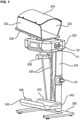
- figure 1 shows a peritoneal dialysis machine according to the present invention in a perspective view.
- the peritoneal dialysis machine has a U-shaped base 300 from which a device housing support 310 extends vertically upwards.
- the device housing 320 is located at its upper end.
- the device housing 320 contains the electronics required to operate the device, such as control and regulation units, as well as the operating and/or display units.
- the heating shell 330 Arranged directly above the device housing 320 is the heating shell 330, which is connected directly to it and is used to hold solution bags which contain fresh dialysate to be supplied to the patient.
- the weighing pan 340 serves to accommodate one or more receiving bags into which the used dialysate from the patient ends up.
- the weighing pan 340 is located directly above the floor on which the peritoneal dialysis machine stands with its base 300 .
- the base has a low profile so that the weighing pan 340 can be positioned low.
- the distance between the bottom of the weighing pan 340 and the floor is, for example, a few cm, for example 5 cm to 10 cm and preferably 7.5 cm to 8.5 cm.
- the distance between the bottom of the heating pan 330 and the bottom of the weighing pan 340 is preferably between 80 cm and 1.2 m.
- Fluid control to and from the patient is accomplished via valves, with the valve(s) providing fluid communication between the solution bag(s) located within the heating tray 330 and the patient located on the device housing 320.
- These valves are in figure 1 marked with the reference symbol V1, V2.
- the drainage valve V3, which is located between the patient and the spent dialysate collection bag, is located on the equipment housing support 310. It is located at a height of about 40 cm to 50 cm and preferably 45 cm above the floor. This allows convenient operation by the patient.
- the linkage 335 extends from the rear of the weighing pan 340 upwards to the underside of the device housing 320.
- good accessibility from the front to the weighing pan 340 is provided.
- the linkage 335 is arranged on a load cell 338 which is located on or in the device housing 320 .
- Both the heating bowl 330 and the weighing bowl 340 have a support surface for the bag or bags, which is the bottom. Side walls 332 and 342 extend upwardly from the floor. These have the task of keeping the bag that has been picked up securely in the shell. This is particularly important when a plurality of bags are accommodated in the heating bowl 330 and in the weighing bowl 340 .
- the side walls 332 and 342 may be snap-fitted or pivotable relative to the support surface for easy loading and unloading of the bags.
- the heating bowl 330 is also provided with a top cover 334 which has the task of keeping the heat in the area of the solution bags which are in the heating bowl 330 as much as possible.
- the hose system can be arranged in such a way that it is not weighed by the weighing pan 340 or by the balance.
- it can be attached to structures that are separate from the peritoneal dialysis machine, so that the weight of the tube system does not affect the scales.
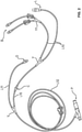
- the lines that are connected to the connectors B are connected via a Y-piece Y1.
- the common line that opens out from this is connected to the line that leads to the load bag via the further Y-piece Y2.
- the length of the line section between the connector C and the Y-piece "Y2" is preferably in the range of 3 cm to 7 cm
- the length of the line section between the Y-piece “Y2” and the Y-piece “Y1” is preferably in Range from 15 cm to 25 cm and
- the length of the line section between the Y-piece "Y2" and the connector L is preferably in the range between 40 cm and 50 cm
- the length of the line section between the Y-piece "Y1" and the connectors B is preferably in the range between 15 cm and 25 cm.
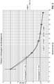
- figure 3 shows a characteristic shown as an example, in which the weight force can be stored on the abscissa and the opening duration of the valves can be stored on the ordinate.
- the invention can provide that, depending on the weight placed on the scales, an opening time of the valves can be determined using a characteristic curve based on the variable change in weight during fluid removal until the patient line is completely filled, in order to ensure an air-free state in the patient line.
- figure 4 shows a characteristic with linearized data series.
- valves are first opened (bag and drainage valves) in order to flush possible particles, e.g. from the opening of the crushing cones, and air into the drainage bag.
- the patient is then prompted to open the hose clamp to the patient line in order to flush it.
- incorrect operation caused by the user can be recognized with the idea according to the invention.
- the invention can be used to check whether the dialysate bag connectors have been properly opened. Initially, only the two tube valves (V1, V2) are opened in order to allow the dialysis fluid to flow to the drainage valve. The drainage valve (V3) remains closed.
- the liquid thus remains in the tubing set. A new static equilibrium is established behind the scales. A change in weight can thus now be determined, since the fluid that has flowed out has not yet reached the drainage bag on the drainage bowl, which is also connected to one of the load cells. Therefore, the change in weight of the dialysate bags on the weighing pan can be used to infer a fluid flow that has taken place and thus a conclusion can be drawn as to whether the bag connectors and/or hose clamps have been opened or a fault condition is present.
- the drainage valve V3 can be opened briefly until a liquid flow is detected and before the liquid has reached the drainage tray or the drainage bag. If it was determined in a first step that the bag connectors and/or the hose clamps were opened properly, a second step can be to check whether the hose clamp to the drainage bag is open. For this purpose, the tube valves V1 and/or V2 and the drainage valve V3 are opened. If a weight change can now be detected between the last measurement (weight change due to fluid flow in the tube system) and the measurement (fluid from the tube system into the drainage bag), this allows the conclusion that the tube clamp to the drainage bag is also open.
- the advantages of the invention are that rinsing can be carried out automatically and the treatment is therefore less prone to error, for example for the introduction of air, for unbroken cones of the solution bag.
- the change in weight when the priming of the tubing or the flushing is started can be recognized and the user can be informed immediately if the priming cannot be started
Landscapes
- Health & Medical Sciences (AREA)
- Heart & Thoracic Surgery (AREA)
- Emergency Medicine (AREA)
- Urology & Nephrology (AREA)
- Public Health (AREA)
- General Health & Medical Sciences (AREA)
- Anesthesiology (AREA)
- Biomedical Technology (AREA)
- Hematology (AREA)
- Life Sciences & Earth Sciences (AREA)
- Animal Behavior & Ethology (AREA)
- Engineering & Computer Science (AREA)
- Veterinary Medicine (AREA)
- Vascular Medicine (AREA)
- Physics & Mathematics (AREA)
- General Physics & Mathematics (AREA)
- Pulmonology (AREA)
- External Artificial Organs (AREA)
Abstract
Description
- Die Erfindung betrifft eine Vorrichtung und ein Verfahren zum automatischen, gewichtsabhängigen Füllen eines Schlauchsystems, insbesondere für einen gravimetrischen Cycler für die Peritonealdialyse mit nur einer Waage, wobei das Schlauchsystem wenigstens drei Leitungsabschnitte umfasst, welche zum Verbinden des Schlauchsystems mit wenigstens einem Drainagebeutel, wenigstens einem Lösungsbeutel und einem Patienten ausgebildet sind.
- Vor dem Beginn von Dialysebehandlungen ist es besonders wichtig, dass die Leitungen dabei verwendeter Schlauchsysteme luftfrei und gefüllt sind. Dies wird durch das Spülen bzw. Füllen des Schlauchs bzw. der Schlauchsysteme mit Dialyseflüssigkeit erreicht. Hierzu soll möglichst nur so viel Dialyselösung aufgewendet werden, wie notwendig ist, um die Luft aus dem System zu Spülen und den Schlauch mit Flüssigkeit zu befüllen. Da sowohl die Dialysatbehältnisse als auch die Dialyselösung in der Regel transparent sind und die Flüssigkeit verhältnismäßig schnell durch das Schlauchsystem strömt, kann dies zur sicheren Anwendung und effizienten Nutzung der Dialyselösung für den Spülprozess nur unter Einhaltung einer sehr kurzen Reaktionszeit durchgeführt werden.
- Die Begriffe "Spülen" und "Füllen" stellen im Rahmen der Erfindung Synonyme dar.
- Aus dem Stand der Technik sind Vorrichtungen bzw. Verfahren bekannt, welche bspw. mit einem Zentralprozessor arbeiten, welcher mit einer Wägeeinrichtung und einer Uhr verbunden ist um die Füll-, Dwell- und Drainzeit verfolgen zu können. Dabei sind Systeme mit nur einer Waage bekannt. Allerdings finden Füllphase und Drainphase niemals zur gleichen Zeit statt, so dass die Verwendung einer einzelnen Wägeeinrichtung ausreichend ist. Spülprozesse, die sich automatisch steuern lassen und über eine Gewichtsbilanzierung mit nur einer Waage erfasst werden können sind dabei unbekannt.
- Aus dem Stand der Technik sind keine Vorrichtungen oder Verfahren bekannt, die für das Spülen des Schlauchsets, insbesondere bei gravimetrisch arbeitenden Geräten in der Peritonealdialyse mit einer Kennlinie arbeitet, welche gewichtsabhängig die Öffnungszeit der Ventile in Verbindung mit nur einer Waage oder Wägezelle steuert. Bei der erfindungsgemäßen Vorrichtung wird die sich verändernde Gewichtsabnahme während des Fluidablaufs beim Spülprozess berücksichtigt, was ebenfalls nicht aus dem Stand der Technik bekannt ist. Auch sind aus dem Stand der Technik keine Vorrichtungen oder Verfahren bekannt, die eine Erkennung der ordnungsgemäßen Öffnung der Beutel- bzw. Schlauchklemmen erlauben.
- Der Begriff "Beutel" steht im Rahmen der vorliegenden Erfindung stellvertretend für beliebige Behältnisse, unabhängig davon, ob sie starre und/oder flexible Wandungen aufweisen.
- Vor diesem Hintergrund ist es Aufgabe der Erfindung eine verbesserte Vorrichtung bzw. ein verbessertes Verfahren zum Spülen eines Schlauchsystems bereitzustellen, bei dem ein vollständiges Befüllen mit Dialyseflüssigkeit gewährleistet und dabei die Dialysatmenge besser bzw. exakt portionierbar ist. Hierdurch soll nur die tatsächlich benötigte Menge an Dialysat zum Spülen der Schlauchleitungen aufgewendet werden. Eine weitere Aufgabe der Erfindung besteht darin, ein ordnungsgemäßes Überprüfen von Dialysatbeutelkonnektoren und/oder Schlauchklemmen bzw. von entsprechenden Ventilen zu ermöglichen, wodurch die Patientensicherheit und der Bedienkomfort gesteigert werden.
- Diese Aufgabe wird erfindungsgemäß durch ein Verfahren mit den Merkmalen des Anspruchs 1 gelöst. Vorteilhafte Ausbildungen sind Gegenstand der Ansprüche. Demnach ist ein Verfahren zum automatischen, gewichtsabhängigen Spülen bzw. Füllen eines Schlauchsystems, insbesondere für einen gravimetrischen Cycler für die Peritonealdialyse mit nur einer Waage vorgesehen, wobei das Schlauchsystem wenigstens drei Leitungsabschnitte zum Verbinden mit wenigstens einem Drainagebeutel, wenigstens einem Lösungsbeutel und einem Patienten umfasst, wobei ferner wenigstens ein Beutelventil und wenigstens ein Drainageventil geöffnet werden und eine erste Öffnungsdauer der Ventile aus dem mittels der Waage gemessenen Gewichts des Lösungsbeutels und aus einer Kennlinie abgeleitet wird.
- Der Begriff des Lösungsbeutels kann dabei einen einzelnen oder eine Mehrzahl von Lösungsbeuteln umfassen. Die aus der Kennlinie ableitbare Öffnungsdauer kann sich dabei auf die Öffnungsdauer eines oder beider Ventile beziehen. Denkbar ist auch, dass abweichende Öffnungsdauern zu den einzelnen Ventilen hinterlegt sind. Mit den Ventilen gemäß Anspruch 1 können das Beutelventil und das Drainageventil gemeint sein. Verfahrensgemäß kann eine Regelung/Steuerung vorliegen, die mit der Waage gekoppelt sein kann und den Lösungsbeutel bzw. dessen Gewicht erfassen kann. Ferner kann verfahrensgemäß auf die Kennlinie zurückgegriffen werden, welche bspw. in der Regelung/Steuerung implementiert bzw. abgespeichert sein kann. Die Regelung/Steuerung kann so das gemessene Gewicht des Lösungsbeutels mit der hinterlegten Kennlinie abgleichen und aus der Kennlinie eine erste Öffnungsdauer ermitteln, für die die Ventile geöffnet werden sollen. Das Gewicht des Lösungsbeutels ermöglicht es dabei, einen guten Näherungswert für die Zeit zu finden, die erforderlich ist, um das Schlauchsystem mit Dialysatlösung zu füllen.
- Dabei ist es auch denkbar, dass der Luftdruck und/oder die Gerätehöhe bei der Erstellung der Kennlinie berücksichtigt werden.
- In einer bevorzugten Ausführung ist denkbar, dass mittels der Waage erfasst wird, ob die Ventile geöffnet worden sind. Um festzustellen, ob trotz eines entsprechenden Öffnungssignals an die Ventile bspw. eine Fehlfunktion wenigstens eines der Ventile vorliegt, kann mittels der oben erwähnten Regelung/Steuerung während der Öffnungsphase der Ventile das Gewicht des Lösungsbeutels weiterhin erfasst werden. Falls dabei trotz ausgegebenen Signals zum Öffnen der Ventile keine Reduzierung des Gewichts des Lösungsbeutels erfasst wird, kann dies als Hinweis auf eine Fehlfunktion von wenigstens einem der Ventile interpretiert oder auf ein nicht korrekt aufgebautes System geschlossen werden und von der Regelung/Steuerung entsprechend erfasst bzw. angezeigt werden. Hierzu kann verfahrensgemäß ein Hinweis an eine Bedienperson über bspw. eine Anzeige oder Leuchtdiode oder ein akustisches Signal ausgegeben werden.
- In einer weiteren, bevorzugten Ausführung ist denkbar, dass eine Gewichtsabnahme des Lösungsbeutels während der Öffnungsdauer der Ventile mittels der Waage erfasst wird und in Abhängigkeit von der erfassten Gewichtsabnahme die erste Öffnungsdauer modifiziert wird. Hierdurch wird eine zweite, korrigierte Öffnungsdauer errechnet. Wird während der Öffnungsdauer der Ventile bspw. festgestellt, dass das Gewicht des Lösungsbeutels zu langsam oder zu schnell fällt, so kann die erste Öffnungsdauer der Ventile entsprechend verlängert oder verkürzt werden. Hierbei kann berücksichtigt werden, ob die Gewichtsabnahme des Lösungsbeutels einer hinterlegten Soll-Gewichtsabnahme nahekommt bzw. diese erreicht. Ist dies nicht der Fall, so kann die Öffnungsdauer entsprechend so modifiziert bzw. verlängert werden, dass die Soll-Gewichtsabnahme erreicht wird. Umgekehrt kann bei Feststellen einer schnellen Gewichtsabnahme bzw. einer schnellen Annäherung an eine Soll-Gewichtsabnahme die erste Öffnungsdauer so verkürzt werden, dass möglichst keine größere Gewichtsabnahme als die Soll-Gewichtsabnahme auftritt. Die zweite Öffnungsdauer kann somit auch kürzer ausfallen als die erste Öffnungsdauer.
- In einer weiteren bevorzugten Ausführung ist ferner denkbar, dass nach Schließen der Ventile eine Aufforderung an eine Bedienperson ergeht, eine Schlauchklemme zu öffnen und hierdurch Dialyseflüssigkeit in Richtung eines Konnektors geleitet wird. Die Schlauchklemme kann hierbei ein drittes auf das Schlauchsystem wirkende Ventil sein und bspw. manuell von der Bedienperson bedienbar ausgebildet sein. Durch das Öffnen der Schlauchklemme ist es möglich das Schlauchsystem mit einem Patientenzugang bzw. mit einer Patientenleitung zu verbinden. Bei der Bedienperson kann es sich insbesondere um einen Patienten handeln, der eine Peritonealdialyse vorbereitet.
- Ferner kann in einer weiteren, bevorzugten Ausführung vorgesehen sein, dass mittels der Waage erfasst wird, ob die Schlauchklemme geöffnet worden ist. Wurde bspw. eine Aufforderung an eine Bedienperson ausgegeben, die Schlauchklemme zu öffnen und wird im Anschluss daran keine Verringerung des Gewichts des Lösungsbeutels erfasst, so kann dies verfahrensgemäß als Hinweis gedeutet werden, dass die Schlauchklemme weiterhin geschlossen ist. Demnach kann ein entsprechender Hinweis an die Bedienperson bzw. eine entsprechende Warnmeldung ausgegeben werden, die Schlauchklemme zum Durchspülen des entsprechenden Schlauchabschnitts zu öffnen.
- In einer weiteren Ausführungsform kann auch ein gewichtsabhängiger Nachfüllprozess vorgesehen sein. Für ein solches Nachfüllen ist dann eine geringere Zeitspanne für das Öffnen der Ventile vorgesehen.
- Das erfindungsgemäße Verfahren, insbesondere das Spülen bzw. Füllen des Schlauchsystems wird durchgeführt, bevor der Patient an das Schlauchsystem angeschlossen ist. Es findet somit zunächst das Spülen bzw. Füllen des Schlauchsystems statt. Ist dieses abgeschlossen, wird der Patient konnektiert und die Behandlung kann beginnen.
- Die Erfindung ist ferner auf eine Vorrichtung zum automatischen, gewichtsabhängigen Füllen eines Schlauchsystems nach Anspruch 7 gerichtet, insbesondere für einen gravimetrischen Cycler für die Peritonealdialyse mit nur einer Waage gerichtet, wobei das Schlauchsystem wenigstens drei Leitungsabschnitte zum Verbinden mit wenigstens einem Drainagebeutel, wenigstens einem Lösungsbeutel und einem Patienten umfasst, wobei die Vorrichtung eine Regelung/Steuerung umfasst, in der wenigstens eine Kennlinie hinterlegt ist, die Ventil-Öffnungsdauern in Abhängigkeit von dem Gewicht eines Lösungsbeutels angibt. Bei dem Lösungsbeutel kann es sich um einen Behälter für eine Dialysatlösung handeln und die Ventil-Öffnungsdauern können für beide Ventile gleich oder unterschiedlich sein.
- Die Vorrichtung kann dabei in einer bevorzugten Ausführung zum Öffnen von wenigstens einem Beutelventil und/oder Drainageventil in Abhängigkeit von dem Gewicht des Lösungsbeuels eingerichtet sein. Das Öffnen der Ventile kann hierbei automatisch erfolgen, wobei die Ventile entsprechend über die Regelung/Steuerung ansteuerbar sind.
- In einer weiteren Ausführung ist ferner denkbar, dass die Regelung/Steuerung dazu ausgelegt ist, anhand einer erfassten Gewichtsänderung das korrekte Öffnen des Beutelventils und/oder Drainageventils zu verifizieren. Ein korrektes Öffnen der Ventile liegt dann vor, wenn auf ein entsprechendes Signal der Regelung/Steuerung die Ventile auch geöffnet worden sind. Dies kann dadurch festgestellt werden, dass beim Vorliegen eines korrekten Öffnens eine entsprechende Gewichtsreduktion des Lösungsbeutels erfassbar ist. Ist dies nicht der Fall, so ist dies als Hinweis auf ein nicht korrektes Öffnen der Ventile zu deuten und ein entsprechendes Warnsignal kann ausgegeben werden. Umgekehrt kann bei korrektem Öffnen der Ventile ein Bestätigungssignal ausgegeben werden. Hierdurch erfolgt die entsprechende Verifikation.
- In einer weiteren bevorzugten Ausführung kann vorgesehen sein, dass die Vorrichtung eine Ausgabeeinrichtung umfasst, die zum Ausgeben von Informationen an eine Bedienperson ausgebildet ist. Die Ausgabeeinrichtung kann eine Display, eine Leuchte und/oder eine akustische Ausgabeeinrichtung umfassen, die jegliche von der Vorrichtung erfassten Parameter oder ermittelten Informationen entsprechend an eine Bedienperson ausgeben können.
- Es kann auch vorgesehen sein, dass die Regelung/Steuerung dazu ausgelegt ist, anhand einer erfassten Gewichtsänderung das korrekte Öffnen eines weiteren Ventils, insbesondere einer manuell bedienbaren Schlauchklemme zu verifizieren. Wurde bspw. ein Signal an eine Bedienperson gegeben, eine Schlauchklemme zu öffnen und wird von der Regelung/Steuerung eine Gewichtsabnahme des Lösungsbeutels erfasst, so kann dies von der Vorrichtung als Hinweis darauf gedeutet werden, dass die Schlauchklemme tatsächlich geöffnet worden ist, wodurch die Verifizierung der Öffnung erfolgt.
- Weitere Einzelheiten und Vorteile der Erfindung sind anhand der Figuren aufgezeigt. Dabei zeigen:
- Fig. 1:
- eine perspektivische Ansicht einer erfindungsgemäßen Vorrichtung;
- Fig. 2:
- eine Ansicht eines Schlauchsystems;
- Fig. 3:
- eine beispielhaft gezeigte Kennlinie und
- Fig. 4:
- eine beispielhaft gezeigte linearisierte Kennlinie.
-
Figur 1 zeigt ein Peritonealdialysegerät gemäß der vorliegenden Erfindung in einer perspektivischen Ansicht. - Das Peritonealdialysegerät weist einen U-förmigen Standfuß 300 auf, von dem sich nach vertikal oben ein Gerätegehäuseträger 310 erstreckt. An dessen oberen Ende befindet sich das Gerätegehäuse 320. In dem Gerätegehäuse 320 befindet sich die zum Betrieb des Gerätes erforderliche Elektronik, wie z.B. Steuer- und Regelungseinheiten, sowie die Bedien- und/oder Anzeigeeinheiten.
- Unmittelbar oberhalb des Gerätegehäuses 320 ist direkt mit diesem verbunden die Heizschale 330 angeordnet, die zur Aufnahme von Lösungsbeuteln dient, die frisches, dem Patienten zuzuführendes Dialysat enthalten.
- Unten an dem Gerätegehäuse 320 bzw. an der Wägezelle 338 befindet sich ein Gestänge 335, an dem die Wägeschale 340 angeordnet ist. Die Wägeschale 340 dient zur Aufnahme eines oder mehrerer Aufnahmebeutel, in die das gebrauchte, vom Patienten stammende Dialysat gelangt.
- Wie dies aus
Figur 1 ersichtlich ist, befindet sich die Wägeschale 340 unmittelbar über dem Fußboden, auf dem das Peritonealdialysegerät mit seinem Standfuß 300 aufsteht. AusFigur 1 geht weiter hervor, dass der Standfuß ein flaches Profil aufweist, so dass die Wägeschale 340 weit unten angeordnet werden kann. - Der Abstand zwischen dem Boden der Wägeschale 340 und dem Fußboden beträgt beispielsweise wenige cm, z.B. 5 cm bis 10 cm und vorzugsweise 7,5 cm bis 8,5 cm.
- Der Abstand zwischen dem Boden der Heizschale 330 und dem Boden der Wägeschale 340 liegt vorzugsweise zwischen 80 cm und 1,2 m.
- Die Fluidsteuerung zum und vom Patienten erfolgt über Ventile, wobei das oder die Ventile für die Fluidverbindung zwischen dem bzw. den Lösungsbeuteln, die sich in der Heizschale 330 befinden, und dem Patienten am Gerätgehäuse 320 angeordnet sind. Diese Ventile sind in
Figur 1 mit dem Bezugszeichen V1, V2 gekennzeichnet. Das Drainageventil V3, das zwischen dem Patienten und dem Aufnahmebeutel für verbrauchtes Dialysat angeordnet ist, befindet sich an dem Gerätegehäuseträger 310. Es ist in einer Höhe von ca. 40 cm bis 50 cm und vorzugsweise von 45 cm über dem Boden angeordnet. Dies erlaubt eine bequeme Bedienung durch den Patienten. - Wie aus
Figur 1 ersichtlich, erstreckt sich das Gestänge 335 von der Rückseite der Wägeschale 340 nach oben zu der Unterseite des Gerätegehäuses 320. Somit ist eine gute Zugänglichkeit von der Vorderseite zu der Wägeschale 340 gegeben. - Das Gestänge 335 ist an einer Wägezelle 338 angeordnet, die sich an oder in dem Gerätegehäuse 320 befindet.
- Sowohl die Heizschale 330 als auch die Wägeschale 340 weisen eine Auflagefläche für den oder die Beutel auf, die den Boden darstellt. Ausgehend von dem Boden erstrecken sich Seitenwände 332 und 342 nach oben. Diese haben die Aufgabe, die jeweils aufgenommenen Beutel sicher in der Schale zu halten. Dies ist insbesondere dann von Bedeutung, wenn in der Heizschale 330 und in der Wägeschale 340 eine Mehrzahl von Beuteln aufgenommen ist.
- Die Seitenwände 332 und 342 können durch eine Steckverbindung befestigt sein oder relativ zu der Auflagefläche verschwenkbar sein, so dass die Beutel leicht eingelegt und entnommen werden können.
- Die Heizschale 330 ist darüber hinaus mit einer oberen Abdeckung 334 versehen, die die Aufgabe hat, die Wärme möglichst im Bereich der Lösungsbeutel zu halten, die sich in der Heizschale 330 befinden.
- Das Schlauchsystem kann erfindungsgemäß so angeordnet sein, dass es von der Wägeschale 340 bzw. von der Wage nicht gewogen wird. Hierzu kann es an Strukturen befestigt sein, die vom Peritonealdialysegerät getrennt sind, so dass die Gewichtskraft des Schlauchsystems nicht auf die Waage wirkt.
- Wie dies aus
Figur 2 ersichtlich ist, stehen die Leitungen, die mit den Konnektoren B in Verbindung stehen, über ein Y-Stück Y1 in Verbindung. Die aus diesem mündende gemeinsame Leitung steht über das weitere Y-Stück Y2 mit der Leitung in Verbindung, die zu dem Last-Bag führt. - Die Länge des Leitungsabschnittes zwischen dem Konnektor C und dem Y-Stück "Y2" liegt vorzugweise im Bereich von 3 cm bis 7 cm, die Länge des Leitungsabschnittes zwischen dem Y-Stück "Y2" und dem Y-Stück "Y1" liegt vorzugsweise im Bereich von 15 cm bis 25 cm und, die Länge des Leitungsabschnittes zwischen dem Y-Stück "Y2" und dem Konnektor L liegt vorzugsweise im Bereich zwischen 40 cm und 50 cm und die Länge des Leitungsabschnittes zwischen dem Y-Stück "Y1" und den Konnektoren B liegt vorzugsweise im Bereich zwischen 15 cm bis 25 cm.
-
Figur 3 zeigt eine beispielhaft gezeigte Kennlinie, bei der auf der Abszisse die Gewichtskraft und auf der Ordinate die Öffnungsdauer der Ventile hinterlegt sein kann. - Die Erfindung kann vorsehen, dass in Abhängigkeit des auf der Waage aufgelegten Gewichts mittels einer Kennlinie eine Öffnungszeit der Ventile anhand der variablen Gewichtsänderung während des Fluidentnahme bis zum vollständigen Füllen der Patientenleitung ermittelt werden kann um einen luftfreien Zustand in der Patientenleitung zu gewährleisten.
-
Figur 4 zeigt eine Kennlinie mit linearisierten Datenreihen. - Hierzu werden zunächst alle Ventile geöffnet (Beutel- und Drainageventile) um mögliche Partikel, die z.B. vom Öffnen der Brechkonen herrühren können, und Luft in den Drainagebeutel zu spülen. Im Anschluss daran wird der Patient aufgefordert, die Schlauchklemme zur Patientenleitung zu öffnen um diese zu spülen. Gleichzeitig kann mit der erfindungsgemäßen Idee eine anwenderbedingte Fehlbedienung erkannt werden.
- Gerade bei Geräten, die ohne große technische Ausstattung betrieben werden, ist dies oft schwierig zu gewährleisten, da bestimmte Prozessabläufe in der Verantwortung des Anwenders / Patienten liegen. Insbesondere für die Anwendung im Heimbereich ist daher eine erhöhte Patientensicherheit wünschenswert. Mit der Erfindung lässt sich in einer weiteren Ausführungsform eine ordnungsgemäße Öffnung der Dialysatbeutelkonnektoren überprüfen. Dabei werden zunächst nur die beiden Schlauchventile (V1, V2) geöffnet um die Dialyseflüssigkeit bis zum Drainageventil strömen zu lassen. Das Drainageventil (V3) bleibt geschlossen.
- Die Flüssigkeit verbleibt somit im Schlauchset. Es stellt sich ein neues statisches Gleichgewicht hinter der Waage ein. Somit lässt sich nun eine Gewichtsänderung bestimmen, da das abgeflossene Fluid den Drainagebeutel auf der Drainschale noch nicht erreicht hat, welche ebenfalls mit der einen Wägezelle in Verbindung steht. Daher kann über die Gewichtsänderung der Dialysatbeutel auf der Wägeschale auf einen stattgefundenen Fluidfluss geschlossen werden und somit ein Rückschluss erfolgen, ob die Beutelkonnektoren und /oder Schlauchklemmen geöffnet wurden bzw. eine Fehlbedingung vorliegt.
- In einer weiteren Ausführungsform kann das Drainageventil V3 kurzzeitig geöffnet werden, bis ein Flüssigkeitsdurchfluss erkannt wird und bevor die Flüssigkeit die Drainageschale bzw. den Drainagebeutel erreicht hat. Wurde in einem ersten Schritt festgestellt, dass die Beutelkonnektoren und/oder die Schlauchklemmen ordnungsgemäß geöffnet wurden, kann in einem zweiten Schritt geprüft werden, ob die Schlauchklemme zum Drainagebeutel geöffnet ist. Hierzu werden die Schlauchventile V1 und/oder V2 als auch das Drainageventil V3 geöffnet. Lässt sich nun eine Gewichtsänderung zwischen der letzten Messung (Gewichtsänderung aufgrund von Fluidfluss in dem Schlauchsystem) und der Messung (Fluid vom Schlauchsystem in Drainagebeutel) erkennen, so lässt dies den Rückschluss zu, dass auch die Schlauchklemme zum Drainagebeutel geöffnet ist.
- Denkbar ist es, an dem Drainageschlauch ein Flüssigkeitsreservoir anzubringen, um die Trübung des Drainfluids bestimmen zu können.
- Nachteile bestehender Verfahren bzw. Vorrichtungen bestehen darin, dass der Patient den Spülvorgang überwachen muss, Ventile von Hand bedienen muss und schnell beim Schließen der Ventile reagieren muss. Damit sind die bekannten Verfahren bzw. Vorrichtungen fehleranfällig, verlangen einen höheren Patientenaufwand und bieten weniger Patientenkomfort.
- Vorteile der Erfindung bestehen demgegenüber darin, dass ein Spülen automatisch durchgeführt werden kann und die Behandlung damit weniger fehleranfällig bspw. für das Einleiten von Luft, für nicht gebrochene Konen der Lösungsbeutel ist.
- Ein Überfüllen der Patientenleitung und damit ein Auslaufen des Dialysats aus der gelochten Schutzkappe des Patientenkonnektors kann vermieden werden, wodurch eine Kontamination des Patientenkonnektors und eine Bauchfellentzündung vermieden werden.
- Erfindungsgemäß kann die Gewichtsveränderung beim Starten des Priming des Tubing bzw. des Spülens erkannt werden und es kann dem Anwender unmittelbar gemeldet werden, wenn das Priming nicht gestartet werden kann
- Erfindungsgemäß kann ferner erkannt werden, ob ein Füllen der Patientenleitung gestartet werden kann und es kann meldet gemeldet werden, wenn ein Füllen der Patientenleitung nicht möglich ist.
Claims (8)
- Gravimetrischer Cycler für die Peritonealdialyse mit nur einer Waage und einem Schlauchsystem sowie einer Vorrichtung zum automatischen, gewichtsabhängigen Füllen des Schlauchsystems, wobei das Schlauchsystem wenigstens drei Leitungsabschnitte zum Verbinden mit wenigstens einem Drainagebeutel, wenigstens einem Lösungsbeutel und einem Patienten umfasst, dadurch gekennzeichnet, dass der gravimetrische Cycler oberhalb von der Waage (338) eine Heizschale (330) zur Aufnahme von Lösungsbeuteln mit frischem Dialysat und unterhalb von der Waage (338) eine Wägeschale (340) zur Aufnahme eines oder mehrerer Aufnahmebeutel für gebrauchtes Dialysat aufweist, wobei die Vorrichtung eine Regelung/Steuerung umfasst, in der wenigstens eine Kennlinie hinterlegt ist, die Ventil-Öffnungsdauern in Abhängigkeit von dem Gewicht eines Lösungsbeutels angibt.
- Gravimetrischer Cycler nach Anspruch 1, wobei die Wägeschale (340) über ein sich von der Waage (338) nach unten erstreckendes Gestänge (335) mit der Waage (338) mechanisch verbunden ist.
- Gravimetrischer Cycler nach Anspruch 1 oder 2, mit weiterhin einem Träger (310), welcher dazu ausgelegt ist, mittels eines Standfußes (300) aufgestellt zu werden.
- Gravimetrischer Cycler nach einem der vorhergehenden Ansprüche, wobei das Schlauchset ein Y-Stück (Y) aufweist.
- Gravimetrischer Cycler nach einem der vorhergehenden Ansprüche , dadurch gekennzeichnet, dass die Vorrichtung zum Öffnen von wenigstens einem Beutelventil und/oder Drainageventil in Abhängigkeit von dem Gewicht des Lösungsbeuels eingerichtet ist.
- Gravimetrischer Cycler nach einem der vorhergehenden Ansprüche, dadurch gekennzeichnet, dass die Regelung/Steuerung dazu ausgelegt ist, anhand einer erfassten Gewichtsänderung das korrekte Öffnen des Beutelventils und/oder Drainageventils zu verifizieren.
- Gravimetrischer Cycler nach einem der vorhergehenden Ansprüche, dadurch gekennzeichnet, dass die Vorrichtung eine Ausgabeeinrichtung umfasst, die zum Ausgeben von Informationen an eine Bedienperson ausgebildet ist.
- Gravimetrischer Cycler nach einem der vorhergehenden Ansprüche, dadurch gekennzeichnet, dass die Regelung/Steuerung dazu ausgelegt ist, anhand einer erfassten Gewichtsänderung das korrekte Öffnen eines weiteren Ventils, insbesondere einer manuell bedienbaren Schlauchklemme zu verifizieren.
Applications Claiming Priority (3)
| Application Number | Priority Date | Filing Date | Title |
|---|---|---|---|
| DE102016008888.5A DE102016008888A1 (de) | 2016-07-20 | 2016-07-20 | Vorrichtung und ein Verfahren zum automatischen, gewichtsabhängigen Füllen eines Schlauchsystems |
| PCT/EP2017/000887 WO2018015020A1 (de) | 2016-07-20 | 2017-07-20 | Vorrichtung und ein verfahren zum automatischen, gewichtsabhängigen füllen eines schlauchsystems |
| EP17748397.1A EP3488202B1 (de) | 2016-07-20 | 2017-07-20 | Vorrichtung und ein verfahren zum automatischen, gewichtsabhängigen füllen eines schlauchsystems |
Related Parent Applications (1)
| Application Number | Title | Priority Date | Filing Date |
|---|---|---|---|
| EP17748397.1A Division EP3488202B1 (de) | 2016-07-20 | 2017-07-20 | Vorrichtung und ein verfahren zum automatischen, gewichtsabhängigen füllen eines schlauchsystems |
Publications (2)
| Publication Number | Publication Date |
|---|---|
| EP3951331A1 true EP3951331A1 (de) | 2022-02-09 |
| EP3951331B1 EP3951331B1 (de) | 2024-01-31 |
Family
ID=59520854
Family Applications (3)
| Application Number | Title | Priority Date | Filing Date |
|---|---|---|---|
| EP17748397.1A Active EP3488202B1 (de) | 2016-07-20 | 2017-07-20 | Vorrichtung und ein verfahren zum automatischen, gewichtsabhängigen füllen eines schlauchsystems |
| EP21173618.6A Withdrawn EP3896407A1 (de) | 2016-07-20 | 2017-07-20 | Vorrichtung und ein verfahren zum automatischen, gewichtsabhängigen füllen eines schlauchsystems |
| EP21192578.9A Active EP3951331B1 (de) | 2016-07-20 | 2017-07-20 | Gravimetrischer zykler |
Family Applications Before (2)
| Application Number | Title | Priority Date | Filing Date |
|---|---|---|---|
| EP17748397.1A Active EP3488202B1 (de) | 2016-07-20 | 2017-07-20 | Vorrichtung und ein verfahren zum automatischen, gewichtsabhängigen füllen eines schlauchsystems |
| EP21173618.6A Withdrawn EP3896407A1 (de) | 2016-07-20 | 2017-07-20 | Vorrichtung und ein verfahren zum automatischen, gewichtsabhängigen füllen eines schlauchsystems |
Country Status (9)
| Country | Link |
|---|---|
| US (1) | US12181330B2 (de) |
| EP (3) | EP3488202B1 (de) |
| CN (1) | CN109477753B (de) |
| BR (1) | BR112019001098B1 (de) |
| CO (1) | CO2019001482A2 (de) |
| DE (1) | DE102016008888A1 (de) |
| MX (1) | MX392680B (de) |
| RU (1) | RU2745336C2 (de) |
| WO (1) | WO2018015020A1 (de) |
Families Citing this family (4)
| Publication number | Priority date | Publication date | Assignee | Title |
|---|---|---|---|---|
| DE102016008888A1 (de) | 2016-07-20 | 2018-01-25 | Fresenius Medical Care Deutschland Gmbh | Vorrichtung und ein Verfahren zum automatischen, gewichtsabhängigen Füllen eines Schlauchsystems |
| US10814057B2 (en) | 2018-04-05 | 2020-10-27 | Baxter International Inc. | Disposable set for a gravity fed dialysis system |
| DE102020131973A1 (de) | 2020-12-02 | 2022-06-02 | Fresenius Medical Care Deutschland Gmbh | Vorrichtung und ein Verfahren zum Überprüfen des korrekten Aufbaus eines Blutbehandlungsgeräts |
| CN112964340B (zh) * | 2021-02-01 | 2022-07-26 | 焦作大学 | 一种物流管理用称重器 |
Citations (4)
| Publication number | Priority date | Publication date | Assignee | Title |
|---|---|---|---|---|
| WO1984002277A1 (en) * | 1982-12-10 | 1984-06-21 | Baxter Travenol Lab | Peritoneal dialysis apparatus |
| US5445610A (en) * | 1993-01-15 | 1995-08-29 | University Of Cincinnati | Portable peritoneal dialysis cycler |
| US20070276328A1 (en) * | 2006-05-26 | 2007-11-29 | Baxter International Inc. | Automated dialysis system driven by gravity and vacuum |
| WO2013067359A2 (en) * | 2011-11-04 | 2013-05-10 | Deka Products Limited Partnership | Medical treatment system and methods using a plurality of fluid lines |
Family Cites Families (13)
| Publication number | Priority date | Publication date | Assignee | Title |
|---|---|---|---|---|
| SE502020C2 (sv) * | 1994-02-03 | 1995-07-17 | Gambro Ab | Apparat för peritonealdialys |
| US7575564B2 (en) * | 2003-10-28 | 2009-08-18 | Baxter International Inc. | Priming, integrity and head height methods and apparatuses for medical fluid systems |
| US8545425B2 (en) * | 2008-01-18 | 2013-10-01 | Baxter International | Reusable effluent drain container for dialysis and other medical fluid therapies |
| DE102011018601B4 (de) * | 2011-04-21 | 2017-04-06 | Fresenius Medical Care Deutschland Gmbh | Vorrichtung zur extrakorporalen Blutbehandlung und Verfahren zur Überwachung der Flüssigkeitsströmung einer extrakorporalen Blutbehandlungsvorrichtung |
| ES2497215T3 (es) * | 2011-08-30 | 2014-09-22 | Gambro Lundia Ab | Aparato médico para tratamiento extracorpóreo de fluido y procedimiento de cálculo de caudales establecidos en un aparato médico para el aporte o la toma de fluidos |
| CN202314552U (zh) * | 2011-10-14 | 2012-07-11 | 天津市同业科技发展有限公司 | 一种负压集液瓶的称重监测结构 |
| CN105142692B (zh) * | 2013-03-14 | 2018-10-09 | 贝克斯特国际公司 | 具有可再用供能单元的用于腹膜透析交换的系统和方法 |
| DE102013016204A1 (de) * | 2013-09-28 | 2015-04-02 | Fresenius Medical Care Deutschland Gmbh | Sensorik zur Detektion von Phasen und/oder Phasenübergängen bei Peritonealdialysebehandlungen |
| CN204563093U (zh) * | 2015-03-05 | 2015-08-19 | 昆山韦睿医疗科技有限公司 | 一种腹膜透析系统 |
| DE102015010467A1 (de) * | 2015-08-11 | 2017-02-16 | Fresenius Medical Care Deutschland Gmbh | Peritonealdialysegerät |
| DE102016008888A1 (de) | 2016-07-20 | 2018-01-25 | Fresenius Medical Care Deutschland Gmbh | Vorrichtung und ein Verfahren zum automatischen, gewichtsabhängigen Füllen eines Schlauchsystems |
| DE102017111803A1 (de) * | 2017-05-30 | 2018-12-06 | Fresenius Medical Care Deutschland Gmbh | Vorrichtung und Verfahren zur Herstellung einer Peritonealdialyselösung |
| DE102020131973A1 (de) * | 2020-12-02 | 2022-06-02 | Fresenius Medical Care Deutschland Gmbh | Vorrichtung und ein Verfahren zum Überprüfen des korrekten Aufbaus eines Blutbehandlungsgeräts |
-
2016
- 2016-07-20 DE DE102016008888.5A patent/DE102016008888A1/de not_active Ceased
-
2017
- 2017-07-20 MX MX2019000798A patent/MX392680B/es unknown
- 2017-07-20 EP EP17748397.1A patent/EP3488202B1/de active Active
- 2017-07-20 US US16/319,594 patent/US12181330B2/en active Active
- 2017-07-20 RU RU2019104610A patent/RU2745336C2/ru active
- 2017-07-20 BR BR112019001098-0A patent/BR112019001098B1/pt active IP Right Grant
- 2017-07-20 EP EP21173618.6A patent/EP3896407A1/de not_active Withdrawn
- 2017-07-20 EP EP21192578.9A patent/EP3951331B1/de active Active
- 2017-07-20 WO PCT/EP2017/000887 patent/WO2018015020A1/de not_active Ceased
- 2017-07-20 CN CN201780044914.XA patent/CN109477753B/zh active Active
-
2019
- 2019-02-20 CO CONC2019/0001482A patent/CO2019001482A2/es unknown
Patent Citations (4)
| Publication number | Priority date | Publication date | Assignee | Title |
|---|---|---|---|---|
| WO1984002277A1 (en) * | 1982-12-10 | 1984-06-21 | Baxter Travenol Lab | Peritoneal dialysis apparatus |
| US5445610A (en) * | 1993-01-15 | 1995-08-29 | University Of Cincinnati | Portable peritoneal dialysis cycler |
| US20070276328A1 (en) * | 2006-05-26 | 2007-11-29 | Baxter International Inc. | Automated dialysis system driven by gravity and vacuum |
| WO2013067359A2 (en) * | 2011-11-04 | 2013-05-10 | Deka Products Limited Partnership | Medical treatment system and methods using a plurality of fluid lines |
Also Published As
| Publication number | Publication date |
|---|---|
| MX392680B (es) | 2025-03-24 |
| WO2018015020A1 (de) | 2018-01-25 |
| US20190376835A1 (en) | 2019-12-12 |
| BR112019001098B1 (pt) | 2023-03-28 |
| CO2019001482A2 (es) | 2019-04-30 |
| EP3488202B1 (de) | 2021-08-25 |
| EP3896407A1 (de) | 2021-10-20 |
| RU2745336C2 (ru) | 2021-03-24 |
| CN109477753B (zh) | 2021-12-21 |
| EP3488202A1 (de) | 2019-05-29 |
| DE102016008888A1 (de) | 2018-01-25 |
| RU2019104610A (ru) | 2020-08-20 |
| US12181330B2 (en) | 2024-12-31 |
| BR112019001098A2 (pt) | 2019-04-30 |
| MX2019000798A (es) | 2019-06-20 |
| EP3951331B1 (de) | 2024-01-31 |
| RU2019104610A3 (de) | 2020-10-22 |
| CN109477753A (zh) | 2019-03-15 |
Similar Documents
| Publication | Publication Date | Title |
|---|---|---|
| EP2303355B1 (de) | Vorrichtung zur peritonealdialyse | |
| DE102008035742B3 (de) | Vorrichtung zur Peritonealdialyse | |
| DE2754894C2 (de) | Vorrichtung zum Bilanzieren einer einem Patienten entnommenen Flüssigkeit mit einer Ersatzflüssigkeit | |
| DE60007723T2 (de) | Leitungssystem für die extrakorporale blutreinigung und verwendung desselben | |
| EP3488202B1 (de) | Vorrichtung und ein verfahren zum automatischen, gewichtsabhängigen füllen eines schlauchsystems | |
| EP3655056B1 (de) | Verfahren und vorrichtungen zum leeren eines effluentbeutels nach der blutbehandlung | |
| EP3710143B1 (de) | Automatisierte einweg-filtrationsvorrichtung und verfahren zur steuerung einer automatisierten einweg-filtrationsvorrichtung | |
| EP0491981B1 (de) | Automatische Anlage zur Herstellung von Konzentraten durch Mischung von Flüssigkeit mit löslichem Feststoff | |
| WO2012143103A1 (de) | Vorrichtung zur extrakorporalen blutbehandlung und verfahren zur überwachung der flüssigkeitsströmung einer extrakorporalen blutbehandlungsvorrichtung | |
| DE102017111803A1 (de) | Vorrichtung und Verfahren zur Herstellung einer Peritonealdialyselösung | |
| DE102005058012B4 (de) | Verfahren zum Freiblasen eines benetzten Hydrophobfilters und Vorrichtung zur Durchführung des Verfahrens | |
| EP3407931B1 (de) | Verfahren zum regeln einer heizvorrichtung zum erwärmen eines fluids für einen dialysierflüssigkeitskreislauf, steuervorrichtung sowie blutbehandlungsvorrichtung | |
| EP3413950B1 (de) | Vorrichtung zur extrakorporalen blutbehandlung | |
| DE1907906C3 (de) | Verfahren zum Aufrechterhalten eines gleichen und dauernden Flüssigkeitsstromes zu und von einem mit Unterbrechung arbeitenden Gerät und eine Vorrichtung zum Durchführen dieses Verfahrens | |
| EP3487552B1 (de) | Verfahren zur beladung eines medizinischen gerätes | |
| DE102020131973A1 (de) | Vorrichtung und ein Verfahren zum Überprüfen des korrekten Aufbaus eines Blutbehandlungsgeräts | |
| DE102017124927A1 (de) | System zur Vakuum-unterstützten venösen Drainage (VAVD) | |
| DE102008023958A1 (de) | Dosiergerät zur Dosierung einer Lösung in eine Flüssigkeit | |
| DE1523104A1 (de) | Vorrichtung zum Dosieren von fluessigen Reagenzien in intermittierend arbeitenden chemischen Apparaturen | |
| DE102017127394A1 (de) | Verfahren und Vorrichtungen zum Leeren eines Effluentbeutels nach der Blutbehandlung |
Legal Events
| Date | Code | Title | Description |
|---|---|---|---|
| PUAI | Public reference made under article 153(3) epc to a published international application that has entered the european phase |
Free format text: ORIGINAL CODE: 0009012 |
|
| STAA | Information on the status of an ep patent application or granted ep patent |
Free format text: STATUS: THE APPLICATION HAS BEEN PUBLISHED |
|
| AC | Divisional application: reference to earlier application |
Ref document number: 3488202 Country of ref document: EP Kind code of ref document: P |
|
| AK | Designated contracting states |
Kind code of ref document: A1 Designated state(s): AL AT BE BG CH CY CZ DE DK EE ES FI FR GB GR HR HU IE IS IT LI LT LU LV MC MK MT NL NO PL PT RO RS SE SI SK SM TR |
|
| STAA | Information on the status of an ep patent application or granted ep patent |
Free format text: STATUS: REQUEST FOR EXAMINATION WAS MADE |
|
| 17P | Request for examination filed |
Effective date: 20220801 |
|
| RBV | Designated contracting states (corrected) |
Designated state(s): AL AT BE BG CH CY CZ DE DK EE ES FI FR GB GR HR HU IE IS IT LI LT LU LV MC MK MT NL NO PL PT RO RS SE SI SK SM TR |
|
| STAA | Information on the status of an ep patent application or granted ep patent |
Free format text: STATUS: EXAMINATION IS IN PROGRESS |
|
| 17Q | First examination report despatched |
Effective date: 20221212 |
|
| GRAP | Despatch of communication of intention to grant a patent |
Free format text: ORIGINAL CODE: EPIDOSNIGR1 |
|
| STAA | Information on the status of an ep patent application or granted ep patent |
Free format text: STATUS: GRANT OF PATENT IS INTENDED |
|
| INTG | Intention to grant announced |
Effective date: 20230830 |
|
| GRAS | Grant fee paid |
Free format text: ORIGINAL CODE: EPIDOSNIGR3 |
|
| GRAA | (expected) grant |
Free format text: ORIGINAL CODE: 0009210 |
|
| STAA | Information on the status of an ep patent application or granted ep patent |
Free format text: STATUS: THE PATENT HAS BEEN GRANTED |
|
| AC | Divisional application: reference to earlier application |
Ref document number: 3488202 Country of ref document: EP Kind code of ref document: P |
|
| AK | Designated contracting states |
Kind code of ref document: B1 Designated state(s): AL AT BE BG CH CY CZ DE DK EE ES FI FR GB GR HR HU IE IS IT LI LT LU LV MC MK MT NL NO PL PT RO RS SE SI SK SM TR |
|
| REG | Reference to a national code |
Ref country code: GB Ref legal event code: FG4D Free format text: NOT ENGLISH Ref country code: CH Ref legal event code: EP |
|
| REG | Reference to a national code |
Ref country code: DE Ref legal event code: R096 Ref document number: 502017015807 Country of ref document: DE |
|
| REG | Reference to a national code |
Ref country code: IE Ref legal event code: FG4D Free format text: LANGUAGE OF EP DOCUMENT: GERMAN |
|
| REG | Reference to a national code |
Ref country code: LT Ref legal event code: MG9D |
|
| REG | Reference to a national code |
Ref country code: NL Ref legal event code: MP Effective date: 20240131 |
|
| PG25 | Lapsed in a contracting state [announced via postgrant information from national office to epo] |
Ref country code: IS Free format text: LAPSE BECAUSE OF FAILURE TO SUBMIT A TRANSLATION OF THE DESCRIPTION OR TO PAY THE FEE WITHIN THE PRESCRIBED TIME-LIMIT Effective date: 20240531 |
|
| PG25 | Lapsed in a contracting state [announced via postgrant information from national office to epo] |
Ref country code: LT Free format text: LAPSE BECAUSE OF FAILURE TO SUBMIT A TRANSLATION OF THE DESCRIPTION OR TO PAY THE FEE WITHIN THE PRESCRIBED TIME-LIMIT Effective date: 20240131 |
|
| PG25 | Lapsed in a contracting state [announced via postgrant information from national office to epo] |
Ref country code: GR Free format text: LAPSE BECAUSE OF FAILURE TO SUBMIT A TRANSLATION OF THE DESCRIPTION OR TO PAY THE FEE WITHIN THE PRESCRIBED TIME-LIMIT Effective date: 20240501 |
|
| PG25 | Lapsed in a contracting state [announced via postgrant information from national office to epo] |
Ref country code: RS Free format text: LAPSE BECAUSE OF FAILURE TO SUBMIT A TRANSLATION OF THE DESCRIPTION OR TO PAY THE FEE WITHIN THE PRESCRIBED TIME-LIMIT Effective date: 20240430 Ref country code: NL Free format text: LAPSE BECAUSE OF FAILURE TO SUBMIT A TRANSLATION OF THE DESCRIPTION OR TO PAY THE FEE WITHIN THE PRESCRIBED TIME-LIMIT Effective date: 20240131 Ref country code: HR Free format text: LAPSE BECAUSE OF FAILURE TO SUBMIT A TRANSLATION OF THE DESCRIPTION OR TO PAY THE FEE WITHIN THE PRESCRIBED TIME-LIMIT Effective date: 20240131 |
|
| PG25 | Lapsed in a contracting state [announced via postgrant information from national office to epo] |
Ref country code: ES Free format text: LAPSE BECAUSE OF FAILURE TO SUBMIT A TRANSLATION OF THE DESCRIPTION OR TO PAY THE FEE WITHIN THE PRESCRIBED TIME-LIMIT Effective date: 20240131 |
|
| PG25 | Lapsed in a contracting state [announced via postgrant information from national office to epo] |
Ref country code: RS Free format text: LAPSE BECAUSE OF FAILURE TO SUBMIT A TRANSLATION OF THE DESCRIPTION OR TO PAY THE FEE WITHIN THE PRESCRIBED TIME-LIMIT Effective date: 20240430 Ref country code: NO Free format text: LAPSE BECAUSE OF FAILURE TO SUBMIT A TRANSLATION OF THE DESCRIPTION OR TO PAY THE FEE WITHIN THE PRESCRIBED TIME-LIMIT Effective date: 20240430 Ref country code: NL Free format text: LAPSE BECAUSE OF FAILURE TO SUBMIT A TRANSLATION OF THE DESCRIPTION OR TO PAY THE FEE WITHIN THE PRESCRIBED TIME-LIMIT Effective date: 20240131 Ref country code: LT Free format text: LAPSE BECAUSE OF FAILURE TO SUBMIT A TRANSLATION OF THE DESCRIPTION OR TO PAY THE FEE WITHIN THE PRESCRIBED TIME-LIMIT Effective date: 20240131 Ref country code: IS Free format text: LAPSE BECAUSE OF FAILURE TO SUBMIT A TRANSLATION OF THE DESCRIPTION OR TO PAY THE FEE WITHIN THE PRESCRIBED TIME-LIMIT Effective date: 20240531 Ref country code: HR Free format text: LAPSE BECAUSE OF FAILURE TO SUBMIT A TRANSLATION OF THE DESCRIPTION OR TO PAY THE FEE WITHIN THE PRESCRIBED TIME-LIMIT Effective date: 20240131 Ref country code: GR Free format text: LAPSE BECAUSE OF FAILURE TO SUBMIT A TRANSLATION OF THE DESCRIPTION OR TO PAY THE FEE WITHIN THE PRESCRIBED TIME-LIMIT Effective date: 20240501 Ref country code: FI Free format text: LAPSE BECAUSE OF FAILURE TO SUBMIT A TRANSLATION OF THE DESCRIPTION OR TO PAY THE FEE WITHIN THE PRESCRIBED TIME-LIMIT Effective date: 20240131 Ref country code: ES Free format text: LAPSE BECAUSE OF FAILURE TO SUBMIT A TRANSLATION OF THE DESCRIPTION OR TO PAY THE FEE WITHIN THE PRESCRIBED TIME-LIMIT Effective date: 20240131 Ref country code: BG Free format text: LAPSE BECAUSE OF FAILURE TO SUBMIT A TRANSLATION OF THE DESCRIPTION OR TO PAY THE FEE WITHIN THE PRESCRIBED TIME-LIMIT Effective date: 20240131 |
|
| PG25 | Lapsed in a contracting state [announced via postgrant information from national office to epo] |
Ref country code: PL Free format text: LAPSE BECAUSE OF FAILURE TO SUBMIT A TRANSLATION OF THE DESCRIPTION OR TO PAY THE FEE WITHIN THE PRESCRIBED TIME-LIMIT Effective date: 20240131 Ref country code: PT Free format text: LAPSE BECAUSE OF FAILURE TO SUBMIT A TRANSLATION OF THE DESCRIPTION OR TO PAY THE FEE WITHIN THE PRESCRIBED TIME-LIMIT Effective date: 20240531 |
|
| PG25 | Lapsed in a contracting state [announced via postgrant information from national office to epo] |
Ref country code: SE Free format text: LAPSE BECAUSE OF FAILURE TO SUBMIT A TRANSLATION OF THE DESCRIPTION OR TO PAY THE FEE WITHIN THE PRESCRIBED TIME-LIMIT Effective date: 20240131 Ref country code: PT Free format text: LAPSE BECAUSE OF FAILURE TO SUBMIT A TRANSLATION OF THE DESCRIPTION OR TO PAY THE FEE WITHIN THE PRESCRIBED TIME-LIMIT Effective date: 20240531 Ref country code: PL Free format text: LAPSE BECAUSE OF FAILURE TO SUBMIT A TRANSLATION OF THE DESCRIPTION OR TO PAY THE FEE WITHIN THE PRESCRIBED TIME-LIMIT Effective date: 20240131 Ref country code: LV Free format text: LAPSE BECAUSE OF FAILURE TO SUBMIT A TRANSLATION OF THE DESCRIPTION OR TO PAY THE FEE WITHIN THE PRESCRIBED TIME-LIMIT Effective date: 20240131 |
|
| PG25 | Lapsed in a contracting state [announced via postgrant information from national office to epo] |
Ref country code: DK Free format text: LAPSE BECAUSE OF FAILURE TO SUBMIT A TRANSLATION OF THE DESCRIPTION OR TO PAY THE FEE WITHIN THE PRESCRIBED TIME-LIMIT Effective date: 20240131 |
|
| PG25 | Lapsed in a contracting state [announced via postgrant information from national office to epo] |
Ref country code: SM Free format text: LAPSE BECAUSE OF FAILURE TO SUBMIT A TRANSLATION OF THE DESCRIPTION OR TO PAY THE FEE WITHIN THE PRESCRIBED TIME-LIMIT Effective date: 20240131 |
|
| PG25 | Lapsed in a contracting state [announced via postgrant information from national office to epo] |
Ref country code: CZ Free format text: LAPSE BECAUSE OF FAILURE TO SUBMIT A TRANSLATION OF THE DESCRIPTION OR TO PAY THE FEE WITHIN THE PRESCRIBED TIME-LIMIT Effective date: 20240131 Ref country code: EE Free format text: LAPSE BECAUSE OF FAILURE TO SUBMIT A TRANSLATION OF THE DESCRIPTION OR TO PAY THE FEE WITHIN THE PRESCRIBED TIME-LIMIT Effective date: 20240131 |
|
| PG25 | Lapsed in a contracting state [announced via postgrant information from national office to epo] |
Ref country code: SK Free format text: LAPSE BECAUSE OF FAILURE TO SUBMIT A TRANSLATION OF THE DESCRIPTION OR TO PAY THE FEE WITHIN THE PRESCRIBED TIME-LIMIT Effective date: 20240131 |
|
| PG25 | Lapsed in a contracting state [announced via postgrant information from national office to epo] |
Ref country code: SM Free format text: LAPSE BECAUSE OF FAILURE TO SUBMIT A TRANSLATION OF THE DESCRIPTION OR TO PAY THE FEE WITHIN THE PRESCRIBED TIME-LIMIT Effective date: 20240131 Ref country code: SK Free format text: LAPSE BECAUSE OF FAILURE TO SUBMIT A TRANSLATION OF THE DESCRIPTION OR TO PAY THE FEE WITHIN THE PRESCRIBED TIME-LIMIT Effective date: 20240131 Ref country code: RO Free format text: LAPSE BECAUSE OF FAILURE TO SUBMIT A TRANSLATION OF THE DESCRIPTION OR TO PAY THE FEE WITHIN THE PRESCRIBED TIME-LIMIT Effective date: 20240131 Ref country code: EE Free format text: LAPSE BECAUSE OF FAILURE TO SUBMIT A TRANSLATION OF THE DESCRIPTION OR TO PAY THE FEE WITHIN THE PRESCRIBED TIME-LIMIT Effective date: 20240131 Ref country code: DK Free format text: LAPSE BECAUSE OF FAILURE TO SUBMIT A TRANSLATION OF THE DESCRIPTION OR TO PAY THE FEE WITHIN THE PRESCRIBED TIME-LIMIT Effective date: 20240131 Ref country code: CZ Free format text: LAPSE BECAUSE OF FAILURE TO SUBMIT A TRANSLATION OF THE DESCRIPTION OR TO PAY THE FEE WITHIN THE PRESCRIBED TIME-LIMIT Effective date: 20240131 |
|
| REG | Reference to a national code |
Ref country code: DE Ref legal event code: R097 Ref document number: 502017015807 Country of ref document: DE |
|
| PG25 | Lapsed in a contracting state [announced via postgrant information from national office to epo] |
Ref country code: IT Free format text: LAPSE BECAUSE OF FAILURE TO SUBMIT A TRANSLATION OF THE DESCRIPTION OR TO PAY THE FEE WITHIN THE PRESCRIBED TIME-LIMIT Effective date: 20240131 |
|
| PLBE | No opposition filed within time limit |
Free format text: ORIGINAL CODE: 0009261 |
|
| STAA | Information on the status of an ep patent application or granted ep patent |
Free format text: STATUS: NO OPPOSITION FILED WITHIN TIME LIMIT |
|
| PG25 | Lapsed in a contracting state [announced via postgrant information from national office to epo] |
Ref country code: IT Free format text: LAPSE BECAUSE OF FAILURE TO SUBMIT A TRANSLATION OF THE DESCRIPTION OR TO PAY THE FEE WITHIN THE PRESCRIBED TIME-LIMIT Effective date: 20240131 |
|
| 26N | No opposition filed |
Effective date: 20241101 |
|
| PG25 | Lapsed in a contracting state [announced via postgrant information from national office to epo] |
Ref country code: MC Free format text: LAPSE BECAUSE OF FAILURE TO SUBMIT A TRANSLATION OF THE DESCRIPTION OR TO PAY THE FEE WITHIN THE PRESCRIBED TIME-LIMIT Effective date: 20240131 |
|
| REG | Reference to a national code |
Ref country code: CH Ref legal event code: PL |
|
| PG25 | Lapsed in a contracting state [announced via postgrant information from national office to epo] |
Ref country code: LU Free format text: LAPSE BECAUSE OF NON-PAYMENT OF DUE FEES Effective date: 20240720 |
|
| PG25 | Lapsed in a contracting state [announced via postgrant information from national office to epo] |
Ref country code: LU Free format text: LAPSE BECAUSE OF NON-PAYMENT OF DUE FEES Effective date: 20240720 |
|
| PG25 | Lapsed in a contracting state [announced via postgrant information from national office to epo] |
Ref country code: SI Free format text: LAPSE BECAUSE OF FAILURE TO SUBMIT A TRANSLATION OF THE DESCRIPTION OR TO PAY THE FEE WITHIN THE PRESCRIBED TIME-LIMIT Effective date: 20240131 Ref country code: BE Free format text: LAPSE BECAUSE OF NON-PAYMENT OF DUE FEES Effective date: 20240731 Ref country code: CH Free format text: LAPSE BECAUSE OF NON-PAYMENT OF DUE FEES Effective date: 20240731 |
|
| REG | Reference to a national code |
Ref country code: BE Ref legal event code: MM Effective date: 20240731 |
|
| PG25 | Lapsed in a contracting state [announced via postgrant information from national office to epo] |
Ref country code: IE Free format text: LAPSE BECAUSE OF NON-PAYMENT OF DUE FEES Effective date: 20240720 |
|
| REG | Reference to a national code |
Ref country code: AT Ref legal event code: MM01 Ref document number: 1654180 Country of ref document: AT Kind code of ref document: T Effective date: 20240720 |
|
| PGFP | Annual fee paid to national office [announced via postgrant information from national office to epo] |
Ref country code: DE Payment date: 20250620 Year of fee payment: 9 |
|
| PG25 | Lapsed in a contracting state [announced via postgrant information from national office to epo] |
Ref country code: AT Free format text: LAPSE BECAUSE OF NON-PAYMENT OF DUE FEES Effective date: 20240720 |
|
| PG25 | Lapsed in a contracting state [announced via postgrant information from national office to epo] |
Ref country code: CY Free format text: LAPSE BECAUSE OF FAILURE TO SUBMIT A TRANSLATION OF THE DESCRIPTION OR TO PAY THE FEE WITHIN THE PRESCRIBED TIME-LIMIT; INVALID AB INITIO Effective date: 20170720 |
|
| PG25 | Lapsed in a contracting state [announced via postgrant information from national office to epo] |
Ref country code: HU Free format text: LAPSE BECAUSE OF FAILURE TO SUBMIT A TRANSLATION OF THE DESCRIPTION OR TO PAY THE FEE WITHIN THE PRESCRIBED TIME-LIMIT; INVALID AB INITIO Effective date: 20170720 |
|
| PG25 | Lapsed in a contracting state [announced via postgrant information from national office to epo] |
Ref country code: TR Free format text: LAPSE BECAUSE OF FAILURE TO SUBMIT A TRANSLATION OF THE DESCRIPTION OR TO PAY THE FEE WITHIN THE PRESCRIBED TIME-LIMIT Effective date: 20240131 |
|
| PGFP | Annual fee paid to national office [announced via postgrant information from national office to epo] |
Ref country code: GB Payment date: 20260618 Year of fee payment: 10 |
|
| PGFP | Annual fee paid to national office [announced via postgrant information from national office to epo] |
Ref country code: FR Payment date: 20260619 Year of fee payment: 10 |