EP3950419A1 - Fahrzeugsitz - Google Patents
Fahrzeugsitz Download PDFInfo
- Publication number
- EP3950419A1 EP3950419A1 EP21186423.6A EP21186423A EP3950419A1 EP 3950419 A1 EP3950419 A1 EP 3950419A1 EP 21186423 A EP21186423 A EP 21186423A EP 3950419 A1 EP3950419 A1 EP 3950419A1
- Authority
- EP
- European Patent Office
- Prior art keywords
- seat
- horizontal
- backrest
- vehicle seat
- seat part
- Prior art date
- Legal status (The legal status is an assumption and is not a legal conclusion. Google has not performed a legal analysis and makes no representation as to the accuracy of the status listed.)
- Granted
Links
Images
Classifications
-
- B—PERFORMING OPERATIONS; TRANSPORTING
- B60—VEHICLES IN GENERAL
- B60N—SEATS SPECIALLY ADAPTED FOR VEHICLES; VEHICLE PASSENGER ACCOMMODATION NOT OTHERWISE PROVIDED FOR
- B60N2/00—Seats specially adapted for vehicles; Arrangement or mounting of seats in vehicles
- B60N2/02—Seats specially adapted for vehicles; Arrangement or mounting of seats in vehicles the seat or part thereof being movable, e.g. adjustable
- B60N2/20—Seats specially adapted for vehicles; Arrangement or mounting of seats in vehicles the seat or part thereof being movable, e.g. adjustable the back-rest being tiltable, e.g. to permit easy access
- B60N2/206—Seats specially adapted for vehicles; Arrangement or mounting of seats in vehicles the seat or part thereof being movable, e.g. adjustable the back-rest being tiltable, e.g. to permit easy access to a position in which it can be used as a support for objects, e.g. as a tray
-
- B—PERFORMING OPERATIONS; TRANSPORTING
- B60—VEHICLES IN GENERAL
- B60N—SEATS SPECIALLY ADAPTED FOR VEHICLES; VEHICLE PASSENGER ACCOMMODATION NOT OTHERWISE PROVIDED FOR
- B60N2/00—Seats specially adapted for vehicles; Arrangement or mounting of seats in vehicles
- B60N2/02—Seats specially adapted for vehicles; Arrangement or mounting of seats in vehicles the seat or part thereof being movable, e.g. adjustable
- B60N2/22—Seats specially adapted for vehicles; Arrangement or mounting of seats in vehicles the seat or part thereof being movable, e.g. adjustable the back-rest being adjustable
- B60N2/2222—Seats specially adapted for vehicles; Arrangement or mounting of seats in vehicles the seat or part thereof being movable, e.g. adjustable the back-rest being adjustable the back-rest having two or more parts
-
- B—PERFORMING OPERATIONS; TRANSPORTING
- B60—VEHICLES IN GENERAL
- B60N—SEATS SPECIALLY ADAPTED FOR VEHICLES; VEHICLE PASSENGER ACCOMMODATION NOT OTHERWISE PROVIDED FOR
- B60N2/00—Seats specially adapted for vehicles; Arrangement or mounting of seats in vehicles
- B60N2/24—Seats specially adapted for vehicles; Arrangement or mounting of seats in vehicles for particular purposes or particular vehicles
- B60N2/30—Non-dismountable or dismountable seats storable in a non-use position, e.g. foldable spare seats
- B60N2/3002—Non-dismountable or dismountable seats storable in a non-use position, e.g. foldable spare seats back-rest movements
- B60N2/3004—Non-dismountable or dismountable seats storable in a non-use position, e.g. foldable spare seats back-rest movements by rotation only
- B60N2/3009—Non-dismountable or dismountable seats storable in a non-use position, e.g. foldable spare seats back-rest movements by rotation only about transversal axis
-
- B—PERFORMING OPERATIONS; TRANSPORTING
- B60—VEHICLES IN GENERAL
- B60N—SEATS SPECIALLY ADAPTED FOR VEHICLES; VEHICLE PASSENGER ACCOMMODATION NOT OTHERWISE PROVIDED FOR
- B60N2/00—Seats specially adapted for vehicles; Arrangement or mounting of seats in vehicles
- B60N2/24—Seats specially adapted for vehicles; Arrangement or mounting of seats in vehicles for particular purposes or particular vehicles
- B60N2/30—Non-dismountable or dismountable seats storable in a non-use position, e.g. foldable spare seats
- B60N2/3038—Cushion movements
- B60N2/304—Cushion movements by rotation only
- B60N2/3045—Cushion movements by rotation only about transversal axis
-
- B—PERFORMING OPERATIONS; TRANSPORTING
- B60—VEHICLES IN GENERAL
- B60N—SEATS SPECIALLY ADAPTED FOR VEHICLES; VEHICLE PASSENGER ACCOMMODATION NOT OTHERWISE PROVIDED FOR
- B60N3/00—Arrangements or adaptations of other passenger fittings, not otherwise provided for
- B60N3/001—Arrangements or adaptations of other passenger fittings, not otherwise provided for of tables or trays
Definitions
- the invention relates to a vehicle seat, in particular a motor vehicle seat, particularly preferably a seat and/or passenger seat in the driver's cab of a commercial vehicle, and a vehicle with such a vehicle seat.
- a vehicle seat in particular a motor vehicle seat, particularly preferably a seat and/or passenger seat in the driver's cab of a commercial vehicle, and a vehicle with such a vehicle seat.
- the invention is therefore based on the object of providing an alternative and/or improved vehicle seat that can be configured for different application situations.
- a vehicle seat preferably a motor vehicle seat
- the vehicle seat includes a seat portion and a backrest.
- the seat part can be pivoted about a horizontal first pivot axis between a horizontal normal position and a non-horizontal, preferably vertical, folded position.
- the backrest comprises a lower partial backrest and an upper partial backrest attached to the lower partial backrest so as to be pivotable about a horizontal second pivot axis.
- the upper partial backrest can be pivoted about the second pivot axis in the direction of the seat part into a horizontal folding position.
- the vehicle seat can be folded up compactly, with the volume of space occupied by the vehicle seat being able to be reduced by folding it in up to two directions.
- the room volume refers to the space required by the Vehicle seat and in particular its extent in the longitudinal direction and/or in the vertical direction of the vehicle when the vehicle seat is installed.
- the volume of space can be reduced in the longitudinal direction by pivoting the seat part into the non-horizontal, preferably vertical, folding position, and in the vertical direction by pivoting the upper partial backrest.
- the space released by the folded vehicle seat can advantageously be used for other purposes, e.g. B. as additional storage space, lounge and / or exercise room.
- additional free space in particular due to the pivoting of the seat part, offers improved access to the driver's cab and greater freedom of movement within the driver's cab when the vehicle seat is used in a driver's cab of a commercial vehicle.
- the upper partial backrest can be a section of the backrest facing away from the seat part.
- the horizontal second pivot axis can be a backrest transverse axis or parallel to the backrest transverse axis.
- the horizontal first pivot axis can be parallel to the transverse axis of the backrest.
- the horizontal first pivot axis can preferably be parallel to the horizontal second pivot axis.
- the horizontal first pivot axis and the horizontal second pivot axis preferably run in the transverse direction of the vehicle.
- the horizontal first pivot axis and the horizontal second pivot axis preferably run transversely to a line of sight of a driver or front passenger in a normal sitting position on the vehicle seat.
- the orientations of the horizontal normal position and the non-horizontal folding position of the seat part refer z. B. on a seat surface of the seat part.
- the seat surface In the normal horizontal position, the seat surface is aligned horizontally, on which the driver or passenger can assume the normal seating position.
- the seat In the vertical folding position, the seat is aligned vertically.
- the orientation of the horizontal folding position of the upper partial backrest refers z. B. on a front or back of the upper partial backrest. In a normal position of the upper partial backrest, this is aligned approximately vertically or has an inclination relative to the seat part, so that the driver or passenger in the normal and upright seating position leans with his back on the front side of the upper partial backrest can. In the horizontal folding position, the front and back of the upper partial backrest is horizontally oriented.
- the horizontal first and second pivot axes can be arranged in such a way that the upper partial backrest can be pivoted into the horizontal folding position when the seat part has already been pivoted into its folding position.
- the horizontal first and second pivot axes can be arranged in such a way that the seat part can be pivoted into its folded position when the upper backrest has already been pivoted into the horizontal folded position.
- the seat part and the upper partial backrest can be given away at the same time in order to simultaneously reduce the volume of space occupied by the vehicle seat in two directions and thus to optimize the compactness of the folded vehicle seat.
- the upper partial backrest when the upper partial backrest is in the horizontal folded position and the seat part is in its folded position, the upper partial backrest protrudes beyond the seat part.
- a compact, cuboid shape of the folded vehicle seat can be achieved and thus the reduction of the volume of space occupied by the vehicle seat can be optimized.
- the upper sub-backrest when the upper sub-backrest is in the horizontal folding position and the seat bottom is in its folded position, the upper sub-backrest can rest on the seat bottom.
- the seat part advantageously serves as a support for the upper part of the backrest, which is particularly advantageous if it is in the horizontal folding position, e.g. B. is used as a table or shelf.
- the horizontal first pivot axis and the horizontal second pivot axis can be positioned and/or the lengths of the seat part and the partial backrests expediently dimensioned such that the upper partial backrest rests on the seat part in the horizontal folded position in its folded position.
- the vehicle seat can also comprise a substructure on which the seat part is held by means of a pivot connection so that it can pivot about the horizontal first pivot axis.
- the substructure can form a cavity that is open towards the seat part.
- the pivot connection may be spaced from an end portion of the seat portion, that of the lower portion backrest in the normal horizontal position is facing or is arranged adjacent to this, be arranged so that when the seat part pivots from the horizontal normal position to its folded position, this end region can dip into the cavity of the substructure.
- the position of the pivot connection can be chosen so that the size of the end portion that can dip into the substructure is as large as possible, e.g. B. is maximized and / or in the folded position of the seat part, a distance between the seat part and a lower inside of the base as small as possible, z. B. is minimized, preferably wherein the seat part does not hit the lower inside of the substructure when pivoting.
- the substructure can have a box shape that is open towards the seat part.
- the swivel connection can be arranged in a central area of the substructure.
- a width of the seat part in the end area which lies between the first pivot axis and the lower partial backrest in the horizontal normal position, can be smaller than a width of the seat part in a front area.
- the width of the front portion may be greater and the width of the tail portion may be less than a width of the cavity of the chassis.
- the front area of the seat part can rest on the substructure in the normal horizontal position and thus achieve a corresponding stability of the seat surface, in particular when the driver or passenger is sitting on the vehicle seat.
- the end area allows the vehicle seat to be immersed in the cavity and thus to be folded up compactly.
- the vehicle seat can also include a locking device for releasably locking the seat part in the folded position. Stability of the folded vehicle seat can advantageously be achieved and unintentional pivoting of the seat part back into the normal horizontal position can be prevented.
- the locking device can be designed as a clamping device, having a receptacle or clamp arranged in the substructure for receiving a clamping part or receptacle or receiving part arranged on the underside of the seat part.
- a clamp and/or receptacle can be positioned in the substructure such that when the seat part is pivoted from the horizontal normal position into its folded position, the end region of the seat part that dips into the cavity is preferably locked on the clamp and/or receptacle in which a tubular section of a support frame of the seat part can be locked to the clamp and/or receptacle.
- the tube section or the support frame of the seat part can thus be used at the same time to form the locking device.
- the upper partial backrest can form a table surface on its rear side.
- a cover to form a table surface can be arranged on the back of the upper partial backrest.
- the vehicle seat according to the invention can also be configured as a table, which z. B. can be used by passengers or drivers during driving breaks.
- This configurability is particularly advantageous for commercial vehicles.
- the space inside the driver's cab can be used more efficiently as living space, since no additional installation of a table is necessary, but the vehicle seat that is not used anyway, in particular a passenger seat, can be used accordingly as a table.
- the upper partial backrest can include a headrest or the headrest can be attached or attachable to an upper end of the upper partial backrest.
- the vehicle seat can be arranged or can be arranged to be horizontally displaceable along a rail arrangement on the underside.
- the vehicle seat can preferably be displaced along the rail arrangement in the longitudinal direction of the rail arrangement.
- the longitudinal direction of the rail arrangement can be the longitudinal direction of the vehicle.
- the rail arrangement can include at least one floor rail and a seat rail that can be displaced in the longitudinal direction relative to this floor rail.
- the underside of the vehicle seat can be mounted on a rotating device, preferably a rotary device-like rotating device, by means of which the vehicle seat can be pivoted about a vertical axis of rotation.
- the vehicle seat includes the rail arrangement and the rotary device, the vehicle seat can be pivotable, preferably simultaneously, in the longitudinal direction and about the vertical axis of rotation.
- the lower partial backrest can be held on the substructure in an adjustable manner, preferably by means of a lower fitting system on the substructure.
- the upper partial backrest can be pivotally attached to the lower partial backrest by means of an upper fitting system.
- the upper and lower fitting system can be formed by fitting systems known from the prior art.
- the upper fitting system can, for example, have two fittings which are arranged along the horizontal second pivot axis on two opposite sides of the upper partial backrest.
- the lower fitting system can have, for example, two fittings which are arranged on two opposite sides of the lower partial backrest along a pivot axis which is parallel to the horizontal second pivot axis.
- the lower fitting system and the upper fitting system can each have a stop which defines a maximum pivoting position in each case.
- the stops can each be set in such a way that the upper partial backrest is in the horizontal folding position when the lower partial backrest and the upper partial backrest are in the maximum pivoting position.
- the seat part can comprise a seat cushion support and a seat cushion arranged on the seat cushion support.
- the upper partial backrest can comprise an upper back cushion support and an upper back cushion arranged on the upper back cushion support.
- the lower partial backrest can comprise a lower back cushion support and a lower back cushion arranged on the lower back cushion support.
- the vehicle seat can be a passenger seat for a driver's cab of a commercial vehicle.
- a vehicle preferably a commercial vehicle
- a vehicle seat as disclosed herein.
- a utility vehicle is a vehicle which, due to its construction and equipment, is designed for the transport of persons, for the transport of goods or for towing trailer vehicles.
- the vehicle can B. be a truck, a semi-trailer truck and / or a bus.
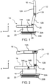
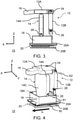
- FIGS. 1-4 12 show the vehicle seat 10 in various configurations according to an embodiment of the invention.
- the directions indicated in the figures relate to preferred vehicle directions when the vehicle seat 10 is in the installed state, namely the vehicle longitudinal direction (X direction), the vehicle transverse direction (Y direction) and the vehicle vertical direction (Z direction).
- the vehicle seat 10 comprises a seat part 14 and a backrest 12.
- the backrest 12 is characterized in that it comprises two partial backrests: a lower partial backrest 12B and an upper partial backrest 12A attached to the lower partial backrest 12B so as to be pivotable about a horizontal second pivot axis S2.
- the upper partial backrest 12A is made of a - in figure 1 shown - normal seating position in which the upper partial backrest 12A is oriented approximately vertically about the second pivot axis S2 in the direction of the seat part 14 in a - in figure 2 shown - horizontal folding position pivotable.
- the upper partial backrest 12A can include a headrest 16 or the headrest 16 can be attached or attachable to an upper end of the upper partial backrest 12A.
- the seat part 14 is about a horizontal first pivot axis S1 between a - in figure 1 shown - horizontal normal position and a non-horizontal folding position is pivotable. As in figure 3 shown, the non-horizontal folding position may correspond to a vertical folding position.
- the horizontal first pivot axis S1 and the horizontal second pivot axis S2 are aligned in the Y direction.
- the seat portion 14 and the upper portion backrest 12A may be pivoted simultaneously to their respective folded positions.
- the horizontal first and second pivot axes S1, S2 can be arranged in such a way and the seat part and the partial backrests can be dimensioned in such a way that the upper partial backrest 12A can be pivoted into the horizontal folded position when the seat part 14 is already pivoted into its folded position, and/or the seat part 14 can be pivoted into its folded position when the upper backrest 12A is already pivoted into the horizontal folded position.
- both the upper partial backrest 12A and the seat part 14 are pivoted, then in this exemplary embodiment the upper partial backrest 12A protrudes beyond the seat part 14 and rests on the seat part.
- the vehicle seat 10 further comprises a substructure 18 on which the seat part 14 is pivotally mounted about the horizontal first pivot axis S1 by means of a pivot connection 28 and which forms a cavity 18A open towards the seat part 14 .
- the pivot connection 28 is spaced from an end region 14B of the seat portion 14 which faces the seat back 12 in the normal horizontal position. Accordingly, this end region 14B can dip into the hollow space 18A of the substructure 18 when the seat part 14 is pivoted from the horizontal normal position into its folded position.
- the substructure 18 can have a box shape that is open towards the seat part 14 .
- a width of the seat part 14 in the end region 14B which lies between the first pivot axis S1 and the backrest 12 in the horizontal normal position, can be smaller than a width of the seat part 14 in a front region 14A, with the width of the front region 14A preferably being larger and the width of the end portion 14B is less than a width of the cavity 18A of the base 18.
- the respective widths refer to the respective dimensions in the Y direction.
- the seat part 14 can be releasably locked in the folded position by means of a locking device (not shown).
- the locking device can, for. B. be designed as a clamping device, having a arranged in the substructure 18 receptacle or clamp for receiving one or one arranged on the underside 14C of the seat part 14 clamping part or receptacle.
- the clamp and/or receptacle in the substructure 18 can be positioned in such a way that when the seat part 14 is pivoted from the horizontal normal position into its folded position, the end region 14B of the seat part 14 plunging into the cavity 18A is locked on the clamp and/or receptacle, preferably in which a tubular section of a support frame of the seat part 14 is locked to the clamp and/or receptacle.
- the vehicle seat 10 can be arranged or can be arranged to be horizontally displaceable along a rail arrangement 20 on the underside.
- the rail arrangement 20 comprises at least one floor rail 20B and a seat rail 20A that can be displaced in a longitudinal adjustment direction L relative to this floor rail 20B, wherein the floor rail 20B can be releasably locked to the seat rail 20A by means of a releasable locking device.
- specified longitudinal adjustment direction L corresponds to the X-direction.
- the vehicle seat 10 can also have a lower fitting system 26, with which the backrest 12 can be held on the substructure 18 in an adjustable manner, and/or can be mounted on the underside on a rotary device, preferably a turntable-like rotary device 50, by means of which the vehicle seat 10 can be rotated about a vertical axis of rotation is pivotable.
- a rotary device preferably a turntable-like rotary device 50
- a table surface can be formed on the back of the upper partial backrest 12A and/or a cover for forming a table surface can be arranged (not shown).
Landscapes
- Engineering & Computer Science (AREA)
- Transportation (AREA)
- Mechanical Engineering (AREA)
- Aviation & Aerospace Engineering (AREA)
- Seats For Vehicles (AREA)
Abstract
Description
- Die Erfindung betrifft einen Fahrzeugsitz, insbesondere einen Kraftfahrzeugsitz, besonders bevorzugt einen Sitz und/oder Beifahrersitz im Führerhaus eines Nutzfahrzeuges, sowie ein Fahrzeug mit einem solchen Fahrzeugsitz.
- Im Allgemeinen sind in einem Kraftfahrzeug mehrere Fahrzeugsitze verbaut, wobei im normalen Betrieb oft nicht alle Fahrzeugsitze besetzt und daher notwendig sind. Insbesondere in einem Nutzfahrzeug ergibt sich oft die Situation, dass sich nur der Fahrer im Fahrerhaus des Nutzfahrzeugs befindet und der Beifahrersitz unbenutzt ist. Es wäre wünschenswert, den Fahrzeugsitz, z.B. den Beifahrersitz, und/oder den Raum, der von dem Fahrzeugsitz eingenommen wird, für andere Zwecke zu verwenden und so den Innenraum des Fahrerhauses effizienter zu nutzen.
- Daher besteht Bedarf für einen alternativen und/oder verbesserten Fahrzeugsitz, der für verschiedene Anwendungssituationen konfigurierbar ist, wenn dieser nicht als Sitzplatz notwendig ist.
- Der Erfindung liegt somit die Aufgabe zu Grunde, einen alternativen und/oder verbesserten Fahrzeugsitz, der für verschiedene Anwendungssituationen konfigurierbar ist, bereitzustellen.
- Die Aufgabe wird gelöst durch die Merkmale der unabhängigen Ansprüche. Vorteilhafte Weiterbildungen sind in den abhängigen Ansprüchen und der Beschreibung angegeben.
- Gemäß einem allgemeinen Aspekt der Erfindung wird ein Fahrzeugsitz, vorzugsweise ein Kraftfahrzeugsitz, bereitgestellt. Der Fahrzeugsitz umfasst ein Sitzteil und eine Rückenlehne. Das Sitzteil ist um eine horizontale erste Schwenkachse zwischen einer horizontalen Normalstellung und einer nicht-horizontalen, vorzugsweise vertikalen, Klappstellung verschwenkbar. Die Rückenlehne umfasst eine untere Teilrückenlehne und eine um eine horizontale zweite Schwenkachse schwenkbar an der unteren Teilrückenlehne angebrachte obere Teilrückenlehne. Die obere Teilrückenlehne ist um die zweite Schwenkachse in Richtung des Sitzteils in eine horizontale Klappstellung verschwenkbar.
- Vorteilhaft kann der Fahrzeugsitz kompakt zusammengeklappt werden, wobei das durch den Fahrzeugsitz eingenommene Raumvolumen durch das Zusammenklappen in bis zu zwei Richtungen verkleinert werden kann. Das Raumvolumen bezieht sich auf den Platzbedarf des Fahrzeugsitzes und insbesondere seine Ausdehnung in Längsrichtung und/oder in Hochrichtung des Fahrzeugs im eingebauten Zustand des Fahrzeugsitzes. Das Raumvolumen kann zum einen in Längsrichtung durch das Verschwenken des Sitzteils in die nicht-horizontale, vorzugsweise vertikale, Klappstellung, zum anderen in Hochrichtung durch das Verschwenken der oberen Teilrückenlehne verkleinert werden.
- Der durch den zusammengeklappten Fahrzeugsitz freigegebene Raum kann vorteilhaft anderweitig verwendet werden, z. B. als zusätzlicher Stauraum, Aufenthalts- und/oder Bewegungsraum. Ferner bietet der zusätzliche Freiraum, insbesondere durch das Verschwenken des Sitzteils, einen verbesserten Einstieg in das Fahrerhaus und eine größere Bewegungsfreiheit innerhalb des Fahrerhauses, bei Verwendung des Fahrzeugsitzes in einem Fahrerhaus eines Nutzfahrzeugs.
- Die obere Teilrückenlehne kann ein vom Sitzteil abgewandter Abschnitt der Rückenlehne sein.
- Die horizontale zweite Schwenkachse kann eine Rückenlehnenquerachse oder parallel zur Rückenlehnenquerachse sein. Die horizontale erste Schwenkachse kann parallel zur Rückenlehnenquerachse sein. Die horizontale erste Schwenkachse kann vorzugsweise parallel zur horizontalen zweiten Schwenkachse sein.
- In einem eingebauten Zustand des Fahrzeugsitzes in einem Fahrzeug verlaufen die horizontale erste Schwenkachse und die horizontale zweite Schwenkachse vorzugsweise in Querrichtung des Fahrzeugs. Die horizontale erste Schwenkachse und die horizontale zweite Schwenkachse verlaufen vorzugsweise quer zu einer Blickrichtung eines Fahrers bzw. Beifahrers in einer normalen Sitzposition auf dem Fahrzeugsitz.
- Die Ausrichtungen der horizontalen Normalstellung und der nicht-horizontalen Klappstellung des Sitzteils beziehen sich z. B. auf eine Sitzfläche des Sitzteils. In der horizontalen Normalstellung ist die Sitzfläche horizontal ausgerichtet, auf der der Fahrer bzw. Mitfahrer die normale Sitzposition einnehmen kann. In der vertikalen Klappstellung ist die Sitzfläche vertikal ausgerichtet.
- Die Ausrichtung der horizontalen Klappstellung der oberen Teilrückenlehne bezieht sich z. B. auf eine Vorderseite oder Rückseite der oberen Teilrückenlehne. In einer Normalstellung des oberen Teilrückenlehne ist diese in etwa vertikal ausgerichtet bzw. weist eine Neigung relativ zum Sitzteil auf, sodass sich der Fahrer bzw. Mitfahrer in der normalen und aufrechten Sitzposition mit seinem Rücken auf der Vorderseite der oberen Teilrückenlehne anlehnen kann. In der horizontalen Klappstellung ist die Vorderseite und Rückseite der oberen Teilrückenlehne horizontal ausgerichtet.
- Gemäß einer besonders bevorzugten Ausführungsform können die horizontalen ersten und zweiten Schwenkachsen derart angeordnet sein, dass die obere Teilrückenlehne in die horizontale Klappstellung verschwenkbar ist, wenn das Sitzteil bereits in dessen Klappstellung verschwenkt ist. Alternativ oder ergänzend können die horizontalen ersten und zweiten Schwenkachsen derart angeordnet sein, dass das Sitzteil in dessen Klappstellung verschwenkbar ist, wenn die obere Rückenlehne bereits in die horizontale Klappstellung verschwenkt ist.
- Vorteilhaft können das Sitzteil und die obere Teilrückenlehne gleichzeitig verschenkt werden, um das durch den Fahrzeugsitz eingenommene Raumvolumen in zwei Richtungen gleichzeitig zu verkleinern und damit die Kompaktheit des zusammenklappten Fahrzeugsitzes zu optimieren.
- Gemäß einer weiteren Ausführungsform kann, wenn sich die obere Teilrückenlehne in der horizontalen Klappstellung und das Sitzteil in dessen Klappstellung befinden, die obere Teilrückenlehne das Sitzteil überragen. Vorteilhaft kann eine kompakte, quaderähnliche Form des zusammengeklappten Fahrzeugsitzes erzielt werden und so die Verkleinerung des durch den Fahrzeugsitz eingenommenen Raumvolumens optimiert werden.
- Ferner kann, wenn sich die obere Teilrückenlehne in der horizontalen Klappstellung und das Sitzteil in dessen Klappstellung befinden, die obere Teilrückenlehne auf dem Sitzteil aufliegen. Hierbei dient vorteilhafterweise das Sitzteil als Stütze für die obere Teilrückenlehne, was besonders vorteilhaft ist, wenn diese in der horizontalen Klappstellung z. B. als Tisch oder Ablage genutzt wird. Anders ausgedrückt können die horizontale erste Schwenkachse und die horizontale zweite Schwenkachse so positioniert und/oder die Längen des Sitzteils und der Teilrückenlehnen zweckmäßig so dimensioniert sein, dass die obere Teilrückenlehne in der horizontalen Klappstellung auf dem Sitzteil in dessen Klappstellung aufliegt.
- Gemäß einer weiteren bevorzugten Ausführungsform kann der Fahrzeugsitz ferner einen Unterbau umfassen, auf dem das Sitzteil mittels einer Schwenkverbindung um die horizontale erste Schwenkachse schwenkbar gehaltert ist. Der Unterbau kann hierbei einen zum Sitzteil hin offenen Hohlraum ausbilden. Die Schwenkverbindung kann beabstandet zu einem Endbereich des Sitzteils, der der unteren Teilrückenlehne in der horizontalen Normalstellung zugewandt ist bzw. benachbart zu dieser angeordnet ist, angeordnet sein, so dass beim Verschwenken des Sitzteils von der horizontalen Normalstellung in dessen Klappstellung dieser Endbereich in den Hohlraum des Unterbaus eintauchen kann. Dadurch kann der Platzbedarf in Fahrzeughochrichtung für das Sitzteil in dessen Klappstellung reduziert werden.
- Vorteilhaft kann die Position der Schwenkverbindung so gewählt sein, dass die Größe des Endbereichs, der in den Unterbau eintauchen kann, möglichst groß, z. B. maximiert ist und/oder in der Klappstellung des Sitzteils ein Abstand zwischen dem Sitzteil und einer unteren Innenseite des Unterbaus möglichst klein, z. B. minimiert ist, vorzugsweise wobei das Sitzteil beim Verschwenken nicht an der unteren Innenseite des Unterbaus anstößt.
- Der Unterbau kann eine zum Sitzteil hin offene Kastenform aufweisen.
- Die Schwenkverbindung kann - in Längsrichtung des Fahrzeugs gesehen - an einem mittleren Bereich des Unterbaus angeordnet sein.
- Gemäß einer weiteren Variante kann eine Breite des Sitzteils in dem Endbereich, der in der horizontalen Normalstellung zwischen der ersten Schwenkachse und der unteren Teilrückenlehne liegt, kleiner sein als eine Breite des Sitzteils in einem Vorderbereich. Die Breite des Vorderbereichs kann größer und die Breite des Endbereichs kann kleiner als eine Breite des Hohlraums des Unterbaus sein.
- Vorteilhaft kann der Vorderbereich des Sitzteils in der horizontalen Normalstellung auf dem Unterbau aufliegen und damit eine entsprechende Stabilität der Sitzfläche erzielen, insbesondere wenn der Fahrer bzw. Mitfahrer auf dem Fahrzeugsitz sitzt. Gleichzeitig ermöglicht der Endbereich das Eintauchen in den Hohlraum und damit das kompakte Zusammenklappen des Fahrzeugsitzes.
- Gemäß einer weiteren Ausführungsvariante kann der Fahrzeugsitz ferner eine Arretiervorrichtung zur lösbaren Arretierung des Sitzteils in der Klappstellung umfassen. Vorteilhaft kann eine Stabilität des zusammengeklappten Fahrzeugsitzes erzielt und ein unbeabsichtigtes Zurückschwenken des Sitzteils in die horizontale Normalstellung verhindert werden.
- Die Arretiervorrichtung kann als Klemmvorrichtung ausgeführt sein, aufweisend eine im Unterbau angeordnete Aufnahme oder Klemme zur Aufnahme eines oder einer an der Unterseite des Sitzteils angeordneten Klemmteils oder Aufnahme bzw. Aufnahmeteils.
- Zur Ausbildung der Arretiervorrichtung im Unterbau kann eine Klemme und/oder Aufnahme so im Unterbau positioniert sein, dass beim Verschwenken des Sitzteils von der horizontalen Normalstellung in dessen Klappstellung der in den Hohlraum eintauchende Endbereich des Sitzteils an der Klemme und/oder Aufnahme arretiert wird, vorzugsweise in dem ein Rohrabschnitt eines Traggestells des Sitzteils an der Klemme und/oder Aufnahme arretiert werden kann. Der Rohrabschnitt bzw. das Traggestell des Sitzteils kann in dieser Variante somit gleichzeitig zur Ausbildung der Arretiervorrichtung genutzt werden.
- Gemäß einer weiteren Ausführungsform kann die obere Teilrückenlehne auf ihrer Rückseite eine Tischfläche ausbilden. Alternativ oder ergänzend kann auf der Rückseite der oberen Teilrückenlehne eine Abdeckung zur Ausbildung einer Tischfläche angeordnet sein.
- Vorteilhaft ist der erfindungsmäßige Fahrzeugsitz zusätzlich als Tisch konfigurierbar, der z. B. von den Passagieren bzw. Fahrer während Fahrpausen verwendet werden kann. Diese Konfigurierbarkeit ist insbesondere für Nutzfahrzeuge von Vorteil. So ist es bei Nutzfahrzeugen üblich, das Fahrerhaus während Fahrpausen und Ruhepausen als Wohn- und Schlafraum zu nutzen. Durch den erfindungsgemäßen Fahrzeugsitz kann der Raum innerhalb des Fahrerhauses effizienter als Wohnraum genutzt werden, da keine zusätzliche Installation eines Tisches notwendig ist, sondern der ohnehin nicht genutzte Fahrzeugsitz, insbesondere ein Beifahrersitz, entsprechend als Tisch genutzt werden kann.
- Gemäß einer weiteren Variante kann die obere Teilrückenlehne eine Kopfstütze umfassen oder an einem oberen Ende der oberen Teilrückenlehne die Kopfstütze angebracht oder anbringbar sein.
- Gemäß einer weiteren Ausführungsform kann der Fahrzeugsitz unterseitig entlang einer Schienenanordnung horizontal verschiebbar angeordnet oder anordbar sein. Vorzugsweise kann der Fahrzeugsitz entlang der Schienenanordnung in Längsrichtung der Schienenanordnung verschoben werden. Im eingebauten Zustand des Fahrzeugsitzes kann die Längsrichtung der Schienenanordnung die Längsrichtung des Fahrzeugs sein. Die Schienenanordnung kann mindestens eine Bodenschiene und eine gegenüber dieser Bodenschiene in Längsrichtung verschiebbare Sitzschiene umfassen.
- Alternativ oder ergänzend kann der Fahrzeugsitz unterseitig auf einer Dreheinrichtung, vorzugsweise einer drehtellerartigen Dreheinrichtung, gelagert sein, mittels derer der Fahrzeugsitz um eine vertikale Drehachse verschwenkbar sein kann.
- Umfasst der Fahrzeugsitz die Schienenanordnung und die Dreheinrichtung, so kann der Fahrzeugsitz, vorzugsweise gleichzeitig, in Längsrichtung und um die vertikale Drehachse verschwenkbar sein.
- Gemäß einer weiteren Variante kann die untere Teilrückenlehne neigungsverstellbar an dem Unterbau gehaltert sein, vorzugsweise mittels eines unteren Beschlagsystems am Unterbau gehaltert sein.
- Die obere Teilrückenlehne kann mittels eines oberen Beschlagsystem verschwenkbar an der unteren Teilrückenlehne angebracht sein.
- Das obere und untere Beschlagsystem können durch aus dem Stand der Technik bekannte Beschlagsysteme ausgebildet sein. Das obere Beschlagsystem kann beispielsweise zwei Beschläge aufweisen, die entlang der horizontalen zweiten Schwenkachse auf zwei gegenüberliegenden Seiten der oberen Teilrückenlehne angeordnet sind. Das untere Beschlagsystem kann beispielsweise zwei Beschläge aufweisen, die entlang einer parallel zur horizontalen zweiten Schwenkachse ausgebildeten Schwenkachse auf zwei gegenüberliegenden Seiten der unteren Teilrückenlehne angeordnet sind.
- Gemäß einer weiteren Variante kann das untere Beschlagsystem und das obere Beschlagsystem jeweils einen Anschlag aufweisen, der jeweils eine maximale Verschwenkstellung festlegt. Die Anschläge können jeweils so festgelegt sein, dass sich bei maximaler Verschwenkstellung der unteren Teilrückenlehne und der oberen Teilrückenlehne die obere Teilrückenlehne in der horizontalen Klappstellung befindet.
- Gemäß einer weiteren Ausführungsform kann das Sitzteil einen Sitzpolsterträger und ein auf dem Sitzpolsterträger angeordnetes Sitzpolster umfassen. Alternativ oder ergänzend kann die obere Teilrückenlehne einen oberen Rückenpolsterträger und ein auf dem oberen Rückenpolsterträger angeordnetes oberes Rückenpolster umfassen. Alternativ oder ergänzend kann die untere Teilrückenlehne einen unteren Rückenpolsterträger und ein auf dem unteren Rückenpolsterträger angeordnetes unteres Rückenpolster umfassen.
- Gemäß einer weiteren Ausführungsform kann der Fahrzeugsitz ein Beifahrersitz für ein Fahrerhaus eines Nutzfahrzeugs sein.
- Gemäß einem weiteren allgemeinen Aspekt der Erfindung wird ein Fahrzeug, vorzugsweise ein Nutzfahrzeug, mit einem Fahrzeugsitz wie hierin offenbart bereitgestellt. Ein Nutzfahrzeug ist ein Fahrzeug, das durch seine Bauart und Einrichtung zur Beförderung von Personen, zum Transport von Gütern oder zum Ziehen von Anhängerfahrzeugen ausgelegt ist. So kann das Fahrzeug z. B. ein Lastkraftwagen, ein Sattelzug und/oder ein Omnibus sein.
- Die zuvor beschriebenen Ausführungsformen, Varianten und Merkmale der Erfindung sind beliebig miteinander kombinierbar. Weitere Einzelheiten und Vorteile der Erfindung werden im Folgenden unter Bezug auf die beigefügten Zeichnungen beschrieben. Es zeigen:
- Figur 1
- eine schematische Seitenansicht eines Fahrzeugsitzes gemäß einer Ausführungsform der Erfindung in einer Sitzkonfiguration;
- Figur 2
- eine schematische Seitenansicht des Fahrzeugsitzes in einer Konfiguration mit oberer Teilrückenlehne in horizontaler Klappstellung;
- Figur 3
- eine schematische Seitenansicht des Fahrzeugsitzes in einer Konfiguration mit oberer Teilrückenlehne in horizontaler Klappstellung und Sitzteil in vertikaler Klappstellung; und
- Figur 4
- eine schematische Schrägansicht des Fahrzeugsitzes in einer Konfiguration gemäß
Figur 3 . - Die
Figuren 1-4 zeigen den Fahrzeugsitz 10 gemäß einer Ausführungsform der Erfindung in verschiedenen Konfigurationen. - Die in den Figuren angegebenen Richtungen beziehen sich auf bevorzugte Fahrzeugrichtungen, wenn sich der Fahrzeugsitz 10 im eingebauten Zustand befindet, nämlich die Fahrzeuglängsrichtung (X-Richtung), die Fahrzeugquerrichtung (Y-Richtung) und die Fahrzeughochrichtung (Z-Richtung).
- Der Fahrzeugsitz 10 umfasst ein Sitzteil 14 und eine Rückenlehne 12.
- Die Rückenlehne 12 zeichnet sich dadurch aus, dass sie zwei Teilrückenlehnen umfasst: eine untere Teilrückenlehne 12B und eine um eine horizontale zweite Schwenkachse S2 schwenkbar an der unteren Teilrückenlehne 12B angebrachte obere Teilrückenlehne 12A. Die obere Teilrückenlehne 12A ist aus einer - in
Figur 1 gezeigten - normalen Sitzstellung, in der die obere Teilrückenlehne 12A in etwa vertikal ausgerichtet ist, um die zweite Schwenkachse S2 in Richtung des Sitzteils 14 in eine - inFigur 2 gezeigte - horizontale Klappstellung verschwenkbar. Ferner kann die obere Teilrückenlehne 12A eine Kopfstütze 16 umfassen oder an einem oberen Ende der oberen Teilrückenlehne 12A die Kopfstütze 16 angebracht oder anbringbar sein. - Das Sitzteil 14 ist um eine horizontale erste Schwenkachse S1 zwischen einer - in
Figur 1 gezeigten - horizontalen Normalstellung und einer nicht-horizontalen Klappstellung verschwenkbar ist. Wie inFigur 3 gezeigt, kann die nicht-horizontale Klappstellung einer vertikalen Klappstellung entsprechen. - Die horizontale erste Schwenkachse S1 und die horizontale zweite Schwenkachse S2 sind in Y-Richtung ausgerichtet.
- Wie in den
Figuren 3 und 4 gezeigt, können das Sitzteil 14 und die obere Teilrückenlehne 12A gleichzeitig in ihre jeweilige Klappstellung verschwenkt sein. Entsprechend können die horizontalen ersten und zweiten Schwenkachsen S1, S2 derart angeordnet und das Sitzteil und die Teilrückenlehnen größenmäßig so dimensioniert sein, dass die obere Teilrückenlehne 12A in die horizontale Klappstellung verschwenkbar ist, wenn das Sitzteil 14 bereits in dessen Klappstellung verschwenkt ist, und/oder das Sitzteil 14 in dessen Klappstellung verschwenkbar ist, wenn die obere Rückenlehne 12A bereits in die horizontale Klappstellung verschwenkt ist. - Sind sowohl die obere Teilrückenlehne 12A als auch das Sitzteil 14 verschwenkt, so überragt in diesem Ausführungsbeispiel die obere Teilrückenlehne 12A das Sitzteil 14 und liegt auf dem Sitzteil auf.
- Gemäß der gezeigten Ausführungsform umfasst der Fahrzeugsitz 10 ferner einen Unterbau 18, auf dem das Sitzteil 14 mittels einer Schwenkverbindung 28 um die horizontale erste Schwenkachse S1 schwenkbar gehaltert ist und der einen zum Sitzteil 14 hin offenen Hohlraum 18A ausbildet. Wie zu erkennen ist, ist die Schwenkverbindung 28 beabstandet zu einem Endbereich 14B des Sitzteils 14, der der Rückenlehne 12 in der horizontalen Normalstellung zugewandt ist, angeordnet. Entsprechend kann dieser Endbereich 14B beim Verschwenken des Sitzteils 14 von der horizontalen Normalstellung in dessen Klappstellung in den Hohlraum 18A des Unterbaus 18 eintauchen.
- Um dieses Eintauchen des Endbereich 14B in den Hohlraum 18A des Unterbaus 18 zu gewährleisten, kann der Unterbau 18 eine zum Sitzteil 14 hin offene Kastenform aufweisen.
- Ferner kann eine Breite des Sitzteils 14 in dem Endbereich 14B, der in der horizontalen Normalstellung zwischen der ersten Schwenkachse S1 und der Rückenlehne 12 liegt, kleiner sein als eine Breite des Sitzteils 14 in einem Vorderbereich 14A, wobei vorzugsweise die Breite des Vorderbereichs 14A größer und die Breite des Endbereichs 14B kleiner als eine Breite des Hohlraums 18A des Unterbaus 18 ist. Die jeweiligen Breiten beziehen sich hierbei auf die jeweiligen Maße in Y-Richtung.
- Das Sitzteil 14 kann mittels einer Arretiervorrichtung (nicht gezeigt) lösbar in der Klappstellung arretiert werden. Die Arretiervorrichtung kann z. B. als Klemmvorrichtung ausgeführt sein, aufweisend eine im Unterbau 18 angeordnete Aufnahme oder Klemme zur Aufnahme eines oder einer an der Unterseite 14C des Sitzteils 14 angeordneten Klemmteils oder Aufnahme. Dazu kann die Klemme und/oder Aufnahme im Unterbau 18 so positioniert ist, dass beim Verschwenken des Sitzteils 14 von der horizontalen Normalstellung in dessen Klappstellung der in den Hohlraum 18A eintauchende Endbereich 14B des Sitzteils 14 an der Klemme und/oder Aufnahme arretiert wird, vorzugsweise in dem ein Rohrabschnitt eines Traggestells des Sitzteils 14 an der Klemme und/oder Aufnahme arretiert wird.
- Der Fahrzeugsitz 10 kann ferner unterseitig entlang einer Schienenanordnung 20 horizontal verschiebbar angeordnet oder anordbar sein. Die Schienenanordnung 20 umfasst mindestens eine Bodenschiene 20B und eine gegenüber dieser Bodenschiene 20B in einer Längsverstellrichtung L verschiebbare Sitzschiene 20A, wobei die Bodenschiene 20B mit der Sitzschiene 20A mittels einer lösbaren Verriegelungseinrichtung lösbar verriegelt werden können. Die in
Figur 4 angegebene Längsverstellrichtung L entspricht der X-Richtung. - Der Fahrzeugsitz 10 kann ferner ein unteres Beschlagsystem 26 aufweisen, mit dem die Rückenlehne 12 neigungsverstellbar am Unterbau 18 gehaltert sein kann, und/oder unterseitig auf einer Dreheinrichtung, vorzugsweise einer drehtellerartigen Dreheinrichtung 50, gelagert sein, mittels derer der Fahrzeugsitz 10 um eine vertikale Drehachse verschwenkbar ist.
- Optional kann auf der Rückseite der oberen Teilrückenlehne 12A eine Tischfläche ausgebildet und/oder eine Abdeckung zur Ausbildung einer Tischfläche angeordnet sein (nicht gezeigt).
- Die Erfindung ist nicht auf die vorstehend beschriebenen bevorzugten Ausführungsformen beschränkt. Vielmehr ist eine Vielzahl von Varianten und Abwandlungen möglich, die ebenfalls von dem Erfindungsgedanken Gebrauch machen und deshalb in den Schutzbereich fallen. Insbesondere beansprucht die Erfindung auch Schutz für den Gegenstand und die Merkmale der Unteransprüche unabhängig von den in Bezug genommenen Ansprüchen. Insbesondere sind die einzelnen Merkmale des unabhängigen Anspruchs 1 jeweils unabhängig voneinander offenbart. Zusätzlich sind auch die Merkmale der Unteransprüche unabhängig von sämtlichen Merkmalen des unabhängigen Anspruchs 1 offenbart.
-
- 10
- Fahrzeugsitz
- 12
- Rückenlehne
- 12A
- Obere Teilrückenlehne
- 12B
- Untere Teilrückenlehne
- 14
- Sitzteil
- 14A
- Vorderbereich des Sitzteils
- 14B
- Endbereich des Sitzteils
- 14C
- Unterseite des Sitzteils
- 16
- Kopfstütze
- 18
- Unterbau
- 18A
- Hohlraum
- 20
- Schienenanordnung
- 20A
- Sitzschiene
- 20B
- Bodenschiene
- 24
- Oberes Beschlagsystem
- 26
- Unteres Beschlagsystem
- 28
- Schwenkverbindung
- 50
- Dreheinrichtung
- L
- Längsverstellrichtung
- S1
- Erste Schwenkachse
- S2
- Zweite Schwenkachse
Claims (16)
- Fahrzeugsitz (10), vorzugsweise Kraftfahrzeugsitz, umfassend:a) ein Sitzteil (14), das um eine horizontale erste Schwenkachse (S1) zwischen einer horizontalen Normalstellung und einer nicht-horizontalen, vorzugsweise vertikalen, Klappstellung verschwenkbar ist; undb) eine Rückenlehne (12), umfassend eine untere Teilrückenlehne (12B) und eine um eine horizontale zweite Schwenkachse (S2) schwenkbar an der unteren Teilrückenlehne (12B) angebrachte obere Teilrückenlehne (12A), wobei die obere Teilrückenlehne (12A) um die zweite Schwenkachse (S2) in Richtung des Sitzteils (14) in eine horizontale Klappstellung verschwenkbar ist.
- Fahrzeugsitz (10) nach Anspruch 1, wobei die horizontalen ersten und zweiten Schwenkachsen (S1, S2) derart angeordnet sind,a) dass die obere Teilrückenlehne (12A) in die horizontale Klappstellung verschwenkbar ist, wenn das Sitzteil (14) bereits in dessen Klappstellung verschwenkt ist; und/oderb) dass das Sitzteil (14) in dessen Klappstellung verschwenkbar ist, wenn die obere Rückenlehne (12A) bereits in die horizontale Klappstellung verschwenkt ist.
- Fahrzeugsitz (10) nach Anspruch 1 oder 2, wobei, wenn sich die obere Teilrückenlehne (12A) in der horizontalen Klappstellung und das Sitzteil (14) in dessen Klappstellung befinden, die obere Teilrückenlehne (12A) das Sitzteil (14) überragt und/oder auf dem Sitzteil aufliegt.
- Fahrzeugsitz (10) nach einem der vorherigen Ansprüche, ferner umfassend einen Unterbau (18), auf dem das Sitzteil (14) mittels einer Schwenkverbindung (28) um die horizontale erste Schwenkachse (S1) schwenkbar gehaltert ist und der einen zum Sitzteil (14) hin offenen Hohlraum (18A) ausbildet, wobei die Schwenkverbindung (28) beabstandet zu einem Endbereich (14B) des Sitzteils (14), der der unteren Teilrückenlehne (12B) in der horizontalen Normalstellung zugewandt ist, angeordnet ist, so dass beim Verschwenken des Sitzteils (14) von der horizontalen Normalstellung in dessen Klappstellung dieser Endbereich (14B) in den Hohlraum (18A) des Unterbaus (18) eintaucht.
- Fahrzeugsitz (10) nach einem der vorhergehenden Ansprüche, wobei eine Breite des Sitzteils (14) in dem Endbereich, der in der horizontalen Normalstellung zwischen der ersten Schwenkachse (S1) und der unteren Teilrückenlehne (12B) liegt, kleiner ist als eine Breite des Sitzteils (14) in einem Vorderbereich (14A).
- Fahrzeugsitz (10) nach den Ansprüchen 4 und 5, wobei die Breite des Vorderbereichs (14A) größer und die Breite des Endbereichs (14B) kleiner als eine Breite des Hohlraums (18A) des Unterbaus (18) ist.
- Fahrzeugsitz (10) nach einem der vorhergehenden Ansprüche, ferner umfassend eine Arretiervorrichtung zur lösbaren Arretierung des Sitzteils (14) in der Klappstellung.
- Fahrzeugsitz (10) nach den Ansprüchen 6 und 7, wobei die Arretiervorrichtung als Klemmvorrichtung ausgeführt ist, aufweisend eine im Unterbau (18) angeordnete Aufnahme oder Klemme zur Aufnahme eines oder einer an der Unterseite des Sitzteils angeordneten Klemmteils oder Aufnahme.
- Fahrzeugsitz nach einem der Ansprüche 7 oder 8, wobei zur Ausbildung der Arrertiervorrichtung im Unterbau (18) eine Klemme und/oder Aufnahme so positioniert ist, dass beim Verschwenken des Sitzteils (14) von der horizontalen Normalstellung in dessen Klappstellung der in den Hohlraum (18A) eintauchende Endbereich (14B) des Sitzteils (14) an der Klemme und/oder Aufnahme arretiert wird, vorzugsweise in dem ein Rohrabschnitt eines Traggestells des Sitzteils (14) an der Klemme und/oder Aufnahme arretiert wird.
- Fahrzeugsitz (10) nach einem der vorhergehenden Ansprüche, wobei die obere Teilrückenlehne (12A) auf ihrer Rückseite eine Tischfläche ausbildet und/oder wobei auf einer Rückseite der oberen Teilrückenlehne (12A) eine Abdeckung zur Ausbildung einer Tischfläche angeordnet ist.
- Fahrzeugsitz (10) nach einem der vorhergehenden Ansprüche, wobei die obere Teilrückenlehne (12A) eine Kopfstütze (16) umfasst oder an einem oberen Ende der oberen Teilrückenlehne (12A) die Kopfstütze (16) angebracht oder anbringbar ist.
- Fahrzeugsitz (10) nach einem der vorhergehenden Ansprüche, wobei der Fahrzeugsitz (10) unterseitiga) entlang einer Schienenanordnung (20) horizontal verschiebbar angeordnet oder anordbar ist; und/oderb) auf einer Dreheinrichtung (50), vorzugsweise einer drehtellerartigen Dreheinrichtung, gelagert ist, mittels derer der Fahrzeugsitz (10) um eine vertikale Drehachse verschwenkbar ist.
- Fahrzeugsitz (10) nach einem der Ansprüche 4 bis 12, wobei die untere Teilrückenlehne (12B) neigungsverstellbar an dem Unterbau (18) gehaltert ist, vorzugsweise mittels eines Rückenlehnenbeschlagssystems (26) am Unterbau (18) gehaltert ist.
- Fahrzeugsitz (10) nach einem der vorhergehenden Ansprüche, wobeia) das Sitzteil (14) einen Sitzpolsterträger und ein auf dem Sitzpolsterträger angeordnetes Sitzpolster umfasst; und/oderb) die obere Teilrückenlehne (12A) einen oberen Rückenpolsterträger und ein auf dem oberen Rückenpolsterträger angeordnetes oberes Rückenpolster umfasst; und/oderc) die untere Teilrückenlehne (12B) einen unteren Rückenpolsterträger und ein auf dem unteren Rückenpolsterträger angeordnetes unteres Rückenpolster umfasst.
- Fahrzeugsitz (10) nach einem der vorhergehenden Ansprüche, wobei der Fahrzeugsitz (10) ein Beifahrersitz für ein Fahrerhaus eines Nutzfahrzeugs ist.
- Fahrzeug, vorzugsweise Nutzfahrzeug, mit einem Fahrzeugsitz (10) gemäß einem der vorhergehenden Ansprüche.
Applications Claiming Priority (1)
| Application Number | Priority Date | Filing Date | Title |
|---|---|---|---|
| DE102020120853.7A DE102020120853A1 (de) | 2020-08-07 | 2020-08-07 | Fahrzeugsitz |
Publications (2)
| Publication Number | Publication Date |
|---|---|
| EP3950419A1 true EP3950419A1 (de) | 2022-02-09 |
| EP3950419B1 EP3950419B1 (de) | 2024-02-14 |
Family
ID=76971749
Family Applications (1)
| Application Number | Title | Priority Date | Filing Date |
|---|---|---|---|
| EP21186423.6A Active EP3950419B1 (de) | 2020-08-07 | 2021-07-19 | Fahrzeugsitz |
Country Status (2)
| Country | Link |
|---|---|
| EP (1) | EP3950419B1 (de) |
| DE (1) | DE102020120853A1 (de) |
Families Citing this family (1)
| Publication number | Priority date | Publication date | Assignee | Title |
|---|---|---|---|---|
| DE102023210839B4 (de) * | 2023-11-01 | 2026-01-29 | Adient Us Llc | Fahrzeugsitz |
Citations (4)
| Publication number | Priority date | Publication date | Assignee | Title |
|---|---|---|---|---|
| GB2395118A (en) * | 2002-11-09 | 2004-05-19 | Ford Global Tech Llc | Seat assembly having a table extending from upper backrest |
| FR2879535A1 (fr) * | 2004-12-16 | 2006-06-23 | Renault Sas | Siege pour vehicule automobile mobile suivant au moins une position verticale d'arc-boutement |
| CN202439580U (zh) * | 2012-02-29 | 2012-09-19 | 许洋 | 公交车座椅 |
| DE112011105252T5 (de) * | 2011-05-18 | 2014-02-13 | Volvo Lastvagnar Ab | Fahrerkabine für einen Schwerlastkraftwagen |
Family Cites Families (7)
| Publication number | Priority date | Publication date | Assignee | Title |
|---|---|---|---|---|
| US557406A (en) | 1896-03-31 | linn x | ||
| FR2696386B1 (fr) | 1992-10-07 | 1994-12-30 | Peugeot | Siège escamotable pour véhicule automobile. |
| FR2817811B1 (fr) | 2000-12-12 | 2004-11-26 | Faurecia Sieges Automobile | Siege de vehicule transformable |
| DE10257171B4 (de) | 2002-12-03 | 2014-09-11 | Volkswagen Ag | Variable Hintersitzlehne mit Multifunktionsklappe |
| FR2901195B1 (fr) | 2006-05-19 | 2009-03-27 | Peugeot Citroen Automobiles Sa | Siege rabatable comprenant un talon d'assise. |
| DE102007060934A1 (de) | 2007-12-14 | 2009-06-18 | Magna Seating (Germany) Gmbh | Kraftfahrzeugsitz |
| DE102014013955B4 (de) | 2014-09-19 | 2024-03-07 | Isringhausen Gmbh & Co. Kg | Fahrzeugsitz, insbesondere für ein Nutzfahrzeug oder ein Campingmobil |
-
2020
- 2020-08-07 DE DE102020120853.7A patent/DE102020120853A1/de active Pending
-
2021
- 2021-07-19 EP EP21186423.6A patent/EP3950419B1/de active Active
Patent Citations (4)
| Publication number | Priority date | Publication date | Assignee | Title |
|---|---|---|---|---|
| GB2395118A (en) * | 2002-11-09 | 2004-05-19 | Ford Global Tech Llc | Seat assembly having a table extending from upper backrest |
| FR2879535A1 (fr) * | 2004-12-16 | 2006-06-23 | Renault Sas | Siege pour vehicule automobile mobile suivant au moins une position verticale d'arc-boutement |
| DE112011105252T5 (de) * | 2011-05-18 | 2014-02-13 | Volvo Lastvagnar Ab | Fahrerkabine für einen Schwerlastkraftwagen |
| CN202439580U (zh) * | 2012-02-29 | 2012-09-19 | 许洋 | 公交车座椅 |
Also Published As
| Publication number | Publication date |
|---|---|
| EP3950419B1 (de) | 2024-02-14 |
| DE102020120853A1 (de) | 2022-02-10 |
Similar Documents
| Publication | Publication Date | Title |
|---|---|---|
| DE69014820T2 (de) | Kraftfahrzeug mit drei Vordersitzen nebeneinander. | |
| EP0001230B1 (de) | Fahrerhaus für Lastkraftwagen mit Wohnwageneinbauten | |
| DE102006044196A1 (de) | Fahrzeugsitz, der gekippt und in eine Stauvertiefung geklappt werden kann | |
| DE102015114762A1 (de) | Flugzeugsitzvorrichtung mit klappbarem Flugzeugsitz | |
| DE202020104560U1 (de) | Fahrzeugsitz | |
| DE112011105252T5 (de) | Fahrerkabine für einen Schwerlastkraftwagen | |
| DE10344086B4 (de) | Faltbares und umlegbares Sitzsystem | |
| DE60113434T2 (de) | Stuhl und bett kombination | |
| EP1759991A1 (de) | Anordnung zum Sitzen und Liegen | |
| DE3022617A1 (de) | Sitzanordnung fuer kraftfahrzeuge | |
| DE202020104559U1 (de) | Fahrzeugsitz | |
| EP3950419B1 (de) | Fahrzeugsitz | |
| DE9112213U1 (de) | Notsitz, insbesondere für Führerkabinen von Nutzfahrzeugen | |
| DE102007052529A1 (de) | Ein Sitz und Sitzanordnung in einem Kraftfahrzeug | |
| DE602005006109T2 (de) | Kraftfahrzeug mit einem zusammenklappbaren und verstaubaren rücksitz | |
| EP1288113B1 (de) | Fahrerhaus eines Nutzfahrzeugs | |
| DE102012018351A1 (de) | Fahrzeugsitz sowie Verfahren zum Verbringen eines Fahrzeugsitzes | |
| DE102015005669A1 (de) | Fondsitz mit einer Armlehne für ein Fahrzeug | |
| DE102004032292B4 (de) | Fahrzeugeinrichtung mit einem klapptischähnlichen Einsatz zur Liegeflächenvergrößerung | |
| DE19804174B4 (de) | Sitz | |
| DE102009033798A1 (de) | Innenausstattung für einen Innenraum eines Kraftwagens | |
| DE102011054408B4 (de) | Wegklappbarer Sitz für ein Kraftfahrzeug | |
| DE102022117840A1 (de) | Anordnung von Sitzen in einem Fahrzeug | |
| DE3714954A1 (de) | Sitz fuer fahrzeuge, insbesondere personenkraftfahrzeuge | |
| EP3950418B1 (de) | Fahrzeugsitz |
Legal Events
| Date | Code | Title | Description |
|---|---|---|---|
| PUAI | Public reference made under article 153(3) epc to a published international application that has entered the european phase |
Free format text: ORIGINAL CODE: 0009012 |
|
| STAA | Information on the status of an ep patent application or granted ep patent |
Free format text: STATUS: THE APPLICATION HAS BEEN PUBLISHED |
|
| AK | Designated contracting states |
Kind code of ref document: A1 Designated state(s): AL AT BE BG CH CY CZ DE DK EE ES FI FR GB GR HR HU IE IS IT LI LT LU LV MC MK MT NL NO PL PT RO RS SE SI SK SM TR |
|
| STAA | Information on the status of an ep patent application or granted ep patent |
Free format text: STATUS: REQUEST FOR EXAMINATION WAS MADE |
|
| 17P | Request for examination filed |
Effective date: 20220719 |
|
| RBV | Designated contracting states (corrected) |
Designated state(s): AL AT BE BG CH CY CZ DE DK EE ES FI FR GB GR HR HU IE IS IT LI LT LU LV MC MK MT NL NO PL PT RO RS SE SI SK SM TR |
|
| GRAP | Despatch of communication of intention to grant a patent |
Free format text: ORIGINAL CODE: EPIDOSNIGR1 |
|
| STAA | Information on the status of an ep patent application or granted ep patent |
Free format text: STATUS: GRANT OF PATENT IS INTENDED |
|
| INTG | Intention to grant announced |
Effective date: 20230915 |
|
| GRAS | Grant fee paid |
Free format text: ORIGINAL CODE: EPIDOSNIGR3 |
|
| GRAA | (expected) grant |
Free format text: ORIGINAL CODE: 0009210 |
|
| STAA | Information on the status of an ep patent application or granted ep patent |
Free format text: STATUS: THE PATENT HAS BEEN GRANTED |
|
| AK | Designated contracting states |
Kind code of ref document: B1 Designated state(s): AL AT BE BG CH CY CZ DE DK EE ES FI FR GB GR HR HU IE IS IT LI LT LU LV MC MK MT NL NO PL PT RO RS SE SI SK SM TR |
|
| REG | Reference to a national code |
Ref country code: GB Ref legal event code: FG4D Free format text: NOT ENGLISH |
|
| REG | Reference to a national code |
Ref country code: CH Ref legal event code: EP |
|
| REG | Reference to a national code |
Ref country code: DE Ref legal event code: R096 Ref document number: 502021002671 Country of ref document: DE |
|
| REG | Reference to a national code |
Ref country code: IE Ref legal event code: FG4D Free format text: LANGUAGE OF EP DOCUMENT: GERMAN |
|
| REG | Reference to a national code |
Ref country code: LT Ref legal event code: MG9D |
|
| REG | Reference to a national code |
Ref country code: NL Ref legal event code: MP Effective date: 20240214 |
|
| PG25 | Lapsed in a contracting state [announced via postgrant information from national office to epo] |
Ref country code: IS Free format text: LAPSE BECAUSE OF FAILURE TO SUBMIT A TRANSLATION OF THE DESCRIPTION OR TO PAY THE FEE WITHIN THE PRESCRIBED TIME-LIMIT Effective date: 20240614 |
|
| PG25 | Lapsed in a contracting state [announced via postgrant information from national office to epo] |
Ref country code: LT Free format text: LAPSE BECAUSE OF FAILURE TO SUBMIT A TRANSLATION OF THE DESCRIPTION OR TO PAY THE FEE WITHIN THE PRESCRIBED TIME-LIMIT Effective date: 20240214 |
|
| PG25 | Lapsed in a contracting state [announced via postgrant information from national office to epo] |
Ref country code: GR Free format text: LAPSE BECAUSE OF FAILURE TO SUBMIT A TRANSLATION OF THE DESCRIPTION OR TO PAY THE FEE WITHIN THE PRESCRIBED TIME-LIMIT Effective date: 20240515 |
|
| PG25 | Lapsed in a contracting state [announced via postgrant information from national office to epo] |
Ref country code: NL Free format text: LAPSE BECAUSE OF FAILURE TO SUBMIT A TRANSLATION OF THE DESCRIPTION OR TO PAY THE FEE WITHIN THE PRESCRIBED TIME-LIMIT Effective date: 20240214 Ref country code: HR Free format text: LAPSE BECAUSE OF FAILURE TO SUBMIT A TRANSLATION OF THE DESCRIPTION OR TO PAY THE FEE WITHIN THE PRESCRIBED TIME-LIMIT Effective date: 20240214 Ref country code: RS Free format text: LAPSE BECAUSE OF FAILURE TO SUBMIT A TRANSLATION OF THE DESCRIPTION OR TO PAY THE FEE WITHIN THE PRESCRIBED TIME-LIMIT Effective date: 20240514 |
|
| PG25 | Lapsed in a contracting state [announced via postgrant information from national office to epo] |
Ref country code: ES Free format text: LAPSE BECAUSE OF FAILURE TO SUBMIT A TRANSLATION OF THE DESCRIPTION OR TO PAY THE FEE WITHIN THE PRESCRIBED TIME-LIMIT Effective date: 20240214 |
|
| PG25 | Lapsed in a contracting state [announced via postgrant information from national office to epo] |
Ref country code: RS Free format text: LAPSE BECAUSE OF FAILURE TO SUBMIT A TRANSLATION OF THE DESCRIPTION OR TO PAY THE FEE WITHIN THE PRESCRIBED TIME-LIMIT Effective date: 20240514 Ref country code: NO Free format text: LAPSE BECAUSE OF FAILURE TO SUBMIT A TRANSLATION OF THE DESCRIPTION OR TO PAY THE FEE WITHIN THE PRESCRIBED TIME-LIMIT Effective date: 20240514 Ref country code: NL Free format text: LAPSE BECAUSE OF FAILURE TO SUBMIT A TRANSLATION OF THE DESCRIPTION OR TO PAY THE FEE WITHIN THE PRESCRIBED TIME-LIMIT Effective date: 20240214 Ref country code: LT Free format text: LAPSE BECAUSE OF FAILURE TO SUBMIT A TRANSLATION OF THE DESCRIPTION OR TO PAY THE FEE WITHIN THE PRESCRIBED TIME-LIMIT Effective date: 20240214 Ref country code: IS Free format text: LAPSE BECAUSE OF FAILURE TO SUBMIT A TRANSLATION OF THE DESCRIPTION OR TO PAY THE FEE WITHIN THE PRESCRIBED TIME-LIMIT Effective date: 20240614 Ref country code: HR Free format text: LAPSE BECAUSE OF FAILURE TO SUBMIT A TRANSLATION OF THE DESCRIPTION OR TO PAY THE FEE WITHIN THE PRESCRIBED TIME-LIMIT Effective date: 20240214 Ref country code: GR Free format text: LAPSE BECAUSE OF FAILURE TO SUBMIT A TRANSLATION OF THE DESCRIPTION OR TO PAY THE FEE WITHIN THE PRESCRIBED TIME-LIMIT Effective date: 20240515 Ref country code: FI Free format text: LAPSE BECAUSE OF FAILURE TO SUBMIT A TRANSLATION OF THE DESCRIPTION OR TO PAY THE FEE WITHIN THE PRESCRIBED TIME-LIMIT Effective date: 20240214 Ref country code: ES Free format text: LAPSE BECAUSE OF FAILURE TO SUBMIT A TRANSLATION OF THE DESCRIPTION OR TO PAY THE FEE WITHIN THE PRESCRIBED TIME-LIMIT Effective date: 20240214 Ref country code: BG Free format text: LAPSE BECAUSE OF FAILURE TO SUBMIT A TRANSLATION OF THE DESCRIPTION OR TO PAY THE FEE WITHIN THE PRESCRIBED TIME-LIMIT Effective date: 20240214 |
|
| PG25 | Lapsed in a contracting state [announced via postgrant information from national office to epo] |
Ref country code: PL Free format text: LAPSE BECAUSE OF FAILURE TO SUBMIT A TRANSLATION OF THE DESCRIPTION OR TO PAY THE FEE WITHIN THE PRESCRIBED TIME-LIMIT Effective date: 20240214 Ref country code: PT Free format text: LAPSE BECAUSE OF FAILURE TO SUBMIT A TRANSLATION OF THE DESCRIPTION OR TO PAY THE FEE WITHIN THE PRESCRIBED TIME-LIMIT Effective date: 20240614 |
|
| PG25 | Lapsed in a contracting state [announced via postgrant information from national office to epo] |
Ref country code: SE Free format text: LAPSE BECAUSE OF FAILURE TO SUBMIT A TRANSLATION OF THE DESCRIPTION OR TO PAY THE FEE WITHIN THE PRESCRIBED TIME-LIMIT Effective date: 20240214 Ref country code: PT Free format text: LAPSE BECAUSE OF FAILURE TO SUBMIT A TRANSLATION OF THE DESCRIPTION OR TO PAY THE FEE WITHIN THE PRESCRIBED TIME-LIMIT Effective date: 20240614 Ref country code: PL Free format text: LAPSE BECAUSE OF FAILURE TO SUBMIT A TRANSLATION OF THE DESCRIPTION OR TO PAY THE FEE WITHIN THE PRESCRIBED TIME-LIMIT Effective date: 20240214 Ref country code: LV Free format text: LAPSE BECAUSE OF FAILURE TO SUBMIT A TRANSLATION OF THE DESCRIPTION OR TO PAY THE FEE WITHIN THE PRESCRIBED TIME-LIMIT Effective date: 20240214 |
|
| PG25 | Lapsed in a contracting state [announced via postgrant information from national office to epo] |
Ref country code: DK Free format text: LAPSE BECAUSE OF FAILURE TO SUBMIT A TRANSLATION OF THE DESCRIPTION OR TO PAY THE FEE WITHIN THE PRESCRIBED TIME-LIMIT Effective date: 20240214 |
|
| PG25 | Lapsed in a contracting state [announced via postgrant information from national office to epo] |
Ref country code: SM Free format text: LAPSE BECAUSE OF FAILURE TO SUBMIT A TRANSLATION OF THE DESCRIPTION OR TO PAY THE FEE WITHIN THE PRESCRIBED TIME-LIMIT Effective date: 20240214 |
|
| PG25 | Lapsed in a contracting state [announced via postgrant information from national office to epo] |
Ref country code: EE Free format text: LAPSE BECAUSE OF FAILURE TO SUBMIT A TRANSLATION OF THE DESCRIPTION OR TO PAY THE FEE WITHIN THE PRESCRIBED TIME-LIMIT Effective date: 20240214 Ref country code: CZ Free format text: LAPSE BECAUSE OF FAILURE TO SUBMIT A TRANSLATION OF THE DESCRIPTION OR TO PAY THE FEE WITHIN THE PRESCRIBED TIME-LIMIT Effective date: 20240214 |
|
| PG25 | Lapsed in a contracting state [announced via postgrant information from national office to epo] |
Ref country code: SK Free format text: LAPSE BECAUSE OF FAILURE TO SUBMIT A TRANSLATION OF THE DESCRIPTION OR TO PAY THE FEE WITHIN THE PRESCRIBED TIME-LIMIT Effective date: 20240214 |
|
| PG25 | Lapsed in a contracting state [announced via postgrant information from national office to epo] |
Ref country code: SM Free format text: LAPSE BECAUSE OF FAILURE TO SUBMIT A TRANSLATION OF THE DESCRIPTION OR TO PAY THE FEE WITHIN THE PRESCRIBED TIME-LIMIT Effective date: 20240214 Ref country code: SK Free format text: LAPSE BECAUSE OF FAILURE TO SUBMIT A TRANSLATION OF THE DESCRIPTION OR TO PAY THE FEE WITHIN THE PRESCRIBED TIME-LIMIT Effective date: 20240214 Ref country code: RO Free format text: LAPSE BECAUSE OF FAILURE TO SUBMIT A TRANSLATION OF THE DESCRIPTION OR TO PAY THE FEE WITHIN THE PRESCRIBED TIME-LIMIT Effective date: 20240214 Ref country code: EE Free format text: LAPSE BECAUSE OF FAILURE TO SUBMIT A TRANSLATION OF THE DESCRIPTION OR TO PAY THE FEE WITHIN THE PRESCRIBED TIME-LIMIT Effective date: 20240214 Ref country code: DK Free format text: LAPSE BECAUSE OF FAILURE TO SUBMIT A TRANSLATION OF THE DESCRIPTION OR TO PAY THE FEE WITHIN THE PRESCRIBED TIME-LIMIT Effective date: 20240214 Ref country code: CZ Free format text: LAPSE BECAUSE OF FAILURE TO SUBMIT A TRANSLATION OF THE DESCRIPTION OR TO PAY THE FEE WITHIN THE PRESCRIBED TIME-LIMIT Effective date: 20240214 |
|
| REG | Reference to a national code |
Ref country code: DE Ref legal event code: R097 Ref document number: 502021002671 Country of ref document: DE |
|
| PG25 | Lapsed in a contracting state [announced via postgrant information from national office to epo] |
Ref country code: IT Free format text: LAPSE BECAUSE OF FAILURE TO SUBMIT A TRANSLATION OF THE DESCRIPTION OR TO PAY THE FEE WITHIN THE PRESCRIBED TIME-LIMIT Effective date: 20240214 |
|
| PLBE | No opposition filed within time limit |
Free format text: ORIGINAL CODE: 0009261 |
|
| STAA | Information on the status of an ep patent application or granted ep patent |
Free format text: STATUS: NO OPPOSITION FILED WITHIN TIME LIMIT |
|
| PG25 | Lapsed in a contracting state [announced via postgrant information from national office to epo] |
Ref country code: IT Free format text: LAPSE BECAUSE OF FAILURE TO SUBMIT A TRANSLATION OF THE DESCRIPTION OR TO PAY THE FEE WITHIN THE PRESCRIBED TIME-LIMIT Effective date: 20240214 |
|
| 26N | No opposition filed |
Effective date: 20241115 |
|
| PG25 | Lapsed in a contracting state [announced via postgrant information from national office to epo] |
Ref country code: MC Free format text: LAPSE BECAUSE OF FAILURE TO SUBMIT A TRANSLATION OF THE DESCRIPTION OR TO PAY THE FEE WITHIN THE PRESCRIBED TIME-LIMIT Effective date: 20240214 |
|
| REG | Reference to a national code |
Ref country code: CH Ref legal event code: PL |
|
| PG25 | Lapsed in a contracting state [announced via postgrant information from national office to epo] |
Ref country code: LU Free format text: LAPSE BECAUSE OF NON-PAYMENT OF DUE FEES Effective date: 20240719 |
|
| PG25 | Lapsed in a contracting state [announced via postgrant information from national office to epo] |
Ref country code: LU Free format text: LAPSE BECAUSE OF NON-PAYMENT OF DUE FEES Effective date: 20240719 |
|
| PG25 | Lapsed in a contracting state [announced via postgrant information from national office to epo] |
Ref country code: SI Free format text: LAPSE BECAUSE OF FAILURE TO SUBMIT A TRANSLATION OF THE DESCRIPTION OR TO PAY THE FEE WITHIN THE PRESCRIBED TIME-LIMIT Effective date: 20240214 Ref country code: CH Free format text: LAPSE BECAUSE OF NON-PAYMENT OF DUE FEES Effective date: 20240731 Ref country code: BE Free format text: LAPSE BECAUSE OF NON-PAYMENT OF DUE FEES Effective date: 20240731 |
|
| REG | Reference to a national code |
Ref country code: BE Ref legal event code: MM Effective date: 20240731 |
|
| PG25 | Lapsed in a contracting state [announced via postgrant information from national office to epo] |
Ref country code: IE Free format text: LAPSE BECAUSE OF NON-PAYMENT OF DUE FEES Effective date: 20240719 |
|
| PGFP | Annual fee paid to national office [announced via postgrant information from national office to epo] |
Ref country code: DE Payment date: 20250728 Year of fee payment: 5 |
|
| PGFP | Annual fee paid to national office [announced via postgrant information from national office to epo] |
Ref country code: AT Payment date: 20251020 Year of fee payment: 5 Ref country code: FR Payment date: 20250725 Year of fee payment: 5 |
|
| PG25 | Lapsed in a contracting state [announced via postgrant information from national office to epo] |
Ref country code: CY Free format text: LAPSE BECAUSE OF FAILURE TO SUBMIT A TRANSLATION OF THE DESCRIPTION OR TO PAY THE FEE WITHIN THE PRESCRIBED TIME-LIMIT; INVALID AB INITIO Effective date: 20210719 |
|
| PG25 | Lapsed in a contracting state [announced via postgrant information from national office to epo] |
Ref country code: HU Free format text: LAPSE BECAUSE OF FAILURE TO SUBMIT A TRANSLATION OF THE DESCRIPTION OR TO PAY THE FEE WITHIN THE PRESCRIBED TIME-LIMIT; INVALID AB INITIO Effective date: 20210719 |
|
| GBPC | Gb: european patent ceased through non-payment of renewal fee |
Effective date: 20250719 |
|
| PG25 | Lapsed in a contracting state [announced via postgrant information from national office to epo] |
Ref country code: GB Free format text: LAPSE BECAUSE OF NON-PAYMENT OF DUE FEES Effective date: 20250719 |