EP3943439B1 - Arbeitsmaschine und verfahren zur steuerung einer arbeitsmaschine - Google Patents
Arbeitsmaschine und verfahren zur steuerung einer arbeitsmaschine Download PDFInfo
- Publication number
- EP3943439B1 EP3943439B1 EP20808825.2A EP20808825A EP3943439B1 EP 3943439 B1 EP3943439 B1 EP 3943439B1 EP 20808825 A EP20808825 A EP 20808825A EP 3943439 B1 EP3943439 B1 EP 3943439B1
- Authority
- EP
- European Patent Office
- Prior art keywords
- slewing
- obstacle
- area
- monitoring
- motor
- Prior art date
- Legal status (The legal status is an assumption and is not a legal conclusion. Google has not performed a legal analysis and makes no representation as to the accuracy of the status listed.)
- Active
Links
Images




Classifications
-
- B—PERFORMING OPERATIONS; TRANSPORTING
- B66—HOISTING; LIFTING; HAULING
- B66C—CRANES; LOAD-ENGAGING ELEMENTS OR DEVICES FOR CRANES, CAPSTANS, WINCHES, OR TACKLES
- B66C13/00—Other constructional features or details
- B66C13/18—Control systems or devices
- B66C13/46—Position indicators for suspended loads or for crane elements
-
- B—PERFORMING OPERATIONS; TRANSPORTING
- B66—HOISTING; LIFTING; HAULING
- B66C—CRANES; LOAD-ENGAGING ELEMENTS OR DEVICES FOR CRANES, CAPSTANS, WINCHES, OR TACKLES
- B66C15/00—Safety gear
- B66C15/04—Safety gear for preventing collisions, e.g. between cranes or trolleys operating on the same track
- B66C15/045—Safety gear for preventing collisions, e.g. between cranes or trolleys operating on the same track electrical
-
- B—PERFORMING OPERATIONS; TRANSPORTING
- B66—HOISTING; LIFTING; HAULING
- B66C—CRANES; LOAD-ENGAGING ELEMENTS OR DEVICES FOR CRANES, CAPSTANS, WINCHES, OR TACKLES
- B66C23/00—Cranes comprising essentially a beam, boom, or triangular structure acting as a cantilever and mounted for translatory of swinging movements in vertical or horizontal planes or a combination of such movements, e.g. jib-cranes, derricks, tower cranes
- B66C23/88—Safety gear
- B66C23/94—Safety gear for limiting slewing movements
-
- B—PERFORMING OPERATIONS; TRANSPORTING
- B66—HOISTING; LIFTING; HAULING
- B66C—CRANES; LOAD-ENGAGING ELEMENTS OR DEVICES FOR CRANES, CAPSTANS, WINCHES, OR TACKLES
- B66C13/00—Other constructional features or details
- B66C13/16—Applications of indicating, registering, or weighing devices
-
- E—FIXED CONSTRUCTIONS
- E02—HYDRAULIC ENGINEERING; FOUNDATIONS; SOIL SHIFTING
- E02D—FOUNDATIONS; EXCAVATIONS; EMBANKMENTS; UNDERGROUND OR UNDERWATER STRUCTURES
- E02D13/00—Accessories for placing or removing piles or bulkheads, e.g. noise attenuating chambers
- E02D13/06—Accessories for placing or removing piles or bulkheads, e.g. noise attenuating chambers for observation while placing
-
- E—FIXED CONSTRUCTIONS
- E02—HYDRAULIC ENGINEERING; FOUNDATIONS; SOIL SHIFTING
- E02F—DREDGING; SOIL-SHIFTING
- E02F9/00—Component parts of dredgers or soil-shifting machines, not restricted to one of the kinds covered by groups E02F3/00 - E02F7/00
- E02F9/20—Drives; Control devices
- E02F9/2025—Particular purposes of control systems not otherwise provided for
- E02F9/2033—Limiting the movement of frames or implements, e.g. to avoid collision between implements and the cabin
-
- E—FIXED CONSTRUCTIONS
- E02—HYDRAULIC ENGINEERING; FOUNDATIONS; SOIL SHIFTING
- E02F—DREDGING; SOIL-SHIFTING
- E02F9/00—Component parts of dredgers or soil-shifting machines, not restricted to one of the kinds covered by groups E02F3/00 - E02F7/00
- E02F9/24—Safety devices, e.g. for preventing overload
-
- E—FIXED CONSTRUCTIONS
- E02—HYDRAULIC ENGINEERING; FOUNDATIONS; SOIL SHIFTING
- E02F—DREDGING; SOIL-SHIFTING
- E02F9/00—Component parts of dredgers or soil-shifting machines, not restricted to one of the kinds covered by groups E02F3/00 - E02F7/00
- E02F9/26—Indicating devices
- E02F9/264—Sensors and their calibration for indicating the position of the work tool
Definitions
- the present invention relates to a work machine including a hydraulic motor that drives a slewing body and a method for controlling the work machine.
- a slewing work machine such as a crane or a hydraulic excavator includes a slewing body and a hydraulic motor that drives the slewing body. Furthermore, the work machine includes a safety device that prevents danger to workers working therearound.
- the work machine determines a danger level based on a detection result of a worker sensor that detects surrounding workers and a slewing direction of the slewing body, and controls stop, low speed operation, or operation maintenance of the work machine according to the danger level (see, for example, Patent Literature1).
- the publication WO 2018/105741 A1 discloses according to its summary a crane that can detect obstacles within a sufficient range while traveling and while doing work.
- a crane that is provided with an obstacle sensor that, during travel, detects the approach of obstacles toward a front side part of a travel body and, during work, detects the approach of obstacles toward a rear side part of a turning body.
- This obstacle sensor has a detection range that is directed from front to rear, or the obstacle sensor has a detection range that is directed from rear to front.
- Patent Literature 1 Japanese Patent Application Laid-Open No. H04-52330
- An object of the present invention is to provide a work machine and a method for controlling the work machine that can take appropriate measures in response to detection of obstacles in each of the area near the slewing body and the area therearound by using as few detection devices such as sensors as possible.
- a crane 10 according to the embodiment of the present invention is one example of a slewing work machine.
- the crane 10 is a work machine that hoists and moves a hoist load 9.
- the crane 10 is a mobile crane will be described.
- the crane 10 includes a lower travelling body 11, an upper slewing body 12, a boom 21, a hook 30, a luffing rope 31, and a hoisting rope 32.
- the upper slewing body 12 includes a slewing frame slewably supported by the lower travelling body 11, a cab 13, a gantry 15, winch devices 16, and a counterweight 17.
- the winch devices 16 include a first winch device 161 and a second winch device 162.
- the gantry 15 is fixed to the slewing frame in a standing up state from the slewing frame of the upper slewing body 12.
- the counterweight 17 is coupled with the slewing frame of the upper slewing body 12 and is disposed at the rear of the slewing frame.
- the lower travelling body 11 is a pedestal that supports the upper slewing body 12 to be able to slew.
- the upper slewing body 12 is located on an upper part of the lower travelling body 11 to be able to slew with respect to the lower travelling body 11.
- the upper slewing body 12 is driven to slew by a slewing motor 441 located on the lower travelling body 11 (see FIG. 2 ).
- the lower travelling body 11 is one example of a lower base.
- the cab 13 is a control cabin.
- the cab 13 is coupled with the slewing frame of the upper slewing body 12 and is disposed at the front of the slewing frame.
- the upper slewing body 12, the boom 21, the hook 30, the luffing rope 31, and the hoisting rope 32 constitute a slewing part 120 that slews integrally.
- the slewing motor 441 is a hydraulic motor.
- the crane 10 also includes a slewing brake device 440 that exerts braking force on the slewing motor 441 (see FIG. 2 ).
- the slewing brake device 440 is a so-called negative brake, and exerts braking force on the slewing motor 441 under circumstances where no hydraulic pressure is applied.
- the crane 10 shown in FIG. 1 is a mobile crane. Therefore, the lower travelling body 11 includes a travelling device 14.
- the travelling device 14 is coupled with a frame of the lower travelling body 11.
- FIG. 1 shows an example in which the travelling device 14 is a crawler type device.
- the boom 21 is supported by the upper slewing body 12 by coupling a root thereof with the slewing frame of the upper slewing body 12.
- the boom 21 is formed to extend in one direction from the slewing frame of the upper slewing body 12 and supports the hoisting rope 32 that suspends the hoist load 9.
- the boom 21 is configured to luff around the root coupled with the upper slewing body 12.
- the hoisting rope 32 is hung on a boom point idler sheave 22 provided at the tip of the boom 21.
- the luffing rope 31 is hung on a gantry sheave 23 provided at the tip of the gantry 15.
- the first winch device 161 supports the boom 21 via the luffing rope 31. Meanwhile, the second winch device 162 supports the hook 30 via the hoisting rope 32.
- the first winch device 161 changes an elevation angle of the boom 21 by winding or unwinding the luffing rope 31. That is, the boom 21 is driven by the first winch device 161 and the luffing rope 31 such that the elevation angle can be changed.
- the second winch device 162 causes the hook 30 to move up and down by winding or unwinding the hoisting rope 32.
- the hoist load 9 is hung on the hook 30.
- the counterweight 17 balances loads of the boom 21, the hook 30, and the hoist load 9.
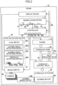
- the crane 10 includes: drive-system devices such as an engine 41, a hydraulic pump unit 42, a hydraulic control valve 43, a pilot pressure valve 43x, and a plurality of hydraulic actuators 44; a manipulation device 5; a controller 6; and a display device 7.
- the crane 10 also includes a state detection device 45 that detects states of various devices included in the crane 10, a plurality of cameras 46, and an image switch 47.
- the manipulation device 5 is a device that receives manipulations of an operator.
- the display device 7 is a device that displays information, for example, a panel display device such as a liquid crystal display unit. In addition, the display device 7 can also display a monitoring image captured by the camera 46.
- the manipulation device 5 includes a boarding and alighting cutoff device 51, a slewing manipulation device 52, a slewing brake manipulation device 53, a manipulation input device 54, and the like.
- the boarding and alighting cutoff device 51 includes a boarding and alighting cutoff lever 511.
- the boarding and alighting cutoff device 51 In response to two types of manipulations on the boarding and alighting cutoff lever 511, the boarding and alighting cutoff device 51 outputs, to the controller 6, a signal instructing a state of the pilot pressure valve 43x to be switched.
- the controller 6 outputs a pilot pressure control signal according to details of the manipulation on the boarding and alighting cutoff lever 511 to the pilot pressure valve 43x.
- the slewing manipulation device 52 includes a slewing lever 521 that can be displaced in two directions from a neutral position.
- the slewing manipulation device 52 is one example of a drive manipulation unit.
- the slewing manipulation device 52 outputs, to the controller 6, a manipulation signal instructing a rotation direction and rotation speed of the slewing motor 441.
- the controller 6 controls a part of the hydraulic control valve 43 corresponding to the slewing motor 441. Specifically, the control is as follows.
- the hydraulic control valve 43 includes a slewing switching valve and one pair of electromagnetic proportional valves.
- the hydraulic pump unit 42 includes a main pump that discharges working oil and a pilot pump that discharges pilot oil.
- the slewing switching valve is interposed between the main pump and the slewing motor 441.
- the slewing switching valve is a pilot-operated hydraulic switching valve including one pair of pilot ports.
- the slewing motor 441 includes one pair of ports that receive the supply of working oil.
- the one pair of electromagnetic proportional valves is interposed between the pilot pump and the one pair of pilot ports of the slewing switching valve.
- One of the one pair of electromagnetic proportional valves is connected to one of the one pair of pilot ports of the slewing switching valve, and the other of the one pair of electromagnetic proportional valves is connected to the other of the one pair of pilot ports of the slewing switching valve.
- the pilot pressure valve 43x is interposed between the pilot pump and the one pair of electromagnetic proportional valves.
- the controller 6 On receipt of input of the manipulation signal corresponding to the manipulating direction and manipulating amount on the slewing lever 521, the controller 6 outputs a drive control signal according to the manipulating amount to one of the one pair of electromagnetic proportional valves corresponding to the manipulating direction.
- the one electromagnetic proportional valve to which the drive control signal is input performs an opening and closing operation to allow the pilot pressure according to the drive control signal to be supplied to the pilot port corresponding to the one electromagnetic proportional valve out of the one pair of pilot ports of the slewing switching valve.
- the slewing switching valve By displacement of a spool in a direction according to the pilot port with a stroke according to the pilot pressure, the slewing switching valve selectively guides the working oil for driving the slewing motor 441 from the main pump to one of the one pair of ports of the slewing motor 441, and adjusts a slewing flow rate, which is a flow rate of the working oil supplied to the slewing motor 441, to the flow rate according to the stroke.
- the slewing brake manipulation device 53 includes a brake button 531. In response to an ON manipulation or OFF manipulation on the brake button 531, the slewing brake manipulation device 53 outputs, to the controller 6, a signal instructing the slewing brake device 440 to be switched to the brake ON state or brake OFF state.
- the controller 6 switches the slewing brake device 440 to the brake ON state or brake OFF state.
- the brake ON state is a state of applying braking force to the slewing motor 441
- the brake OFF state is a state of releasing the braking force on the slewing motor 441.
- the brake ON state means the brake state of the slewing brake device 440
- the brake OFF state means the brake release state of the slewing brake device 440.
- the ON manipulation and the OFF manipulation on the brake button 531 are one example of the brake manipulation and the brake release manipulation, respectively.
- the manipulation input device 54 receives information input by the operator.
- the manipulation input device 54 is a touch panel integrally configured with the display device 7, or the like.
- the manipulation input device 54 may be a device that receives information input by a voice manipulation of the operator.
- the state detection device 45 includes a load meter 451, a luffing angle detection device 452, a slewing angle detection device 453, and an obstacle detection device 454.
- the controller 6 is configured to communicate with other devices such as the state detection device 45 and the manipulation device 5 through a vehicle-mounted network 100 such as a controller area network (CAN). Various detection results of the state detection device 45 are transmitted to the controller 6 through the vehicle-mounted network 100.
- a vehicle-mounted network 100 such as a controller area network (CAN).
- CAN controller area network
- the load meter 451 detects weight of the hoist load 9.
- the luffing angle detection device 452 includes a sensor that detects a luffing angle of the boom 21, that is, an elevation angle of the boom 21.
- the slewing angle detection device 453 includes a sensor that detects an angle at which the upper slewing body 12 slews from a reference direction of the lower travelling body 11.
- the obstacle detection device 454 includes at least one sensor that detects an obstacle existing in a plurality of monitoring areas T0 set in advance with respect to the upper slewing body 12.
- the obstacle is mainly a person.
- the obstacle detection device 454 is configured to individually detect the obstacle existing in each of eight monitoring areas T0 including a front area Ta0, front and left area Tb0, left side area Tc0, rear and left area Td0, front and right area Te0, right side area Tf0, rear and right area Tg0, and lower center area Th0.
- the front area Ta0, front and left area Tb0, left side area Tc0, rear and left area Td0, front and right area Te0, right side area Tf0, and rear and right area Tg0 are areas around the upper slewing body 12.
- these seven monitoring areas T0 may be referred to as outer peripheral monitoring areas.
- the lower center area Th0 is an area in a maintenance hole 12a formed at the bottom of the upper slewing body 12.
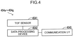
- the obstacle detection device 454 includes seven time of flight (TOF) sensor units 454a to 454g corresponding to the seven monitoring areas T0 (the outer peripheral monitoring areas), and a motion sensor 454h corresponding to the lower center area Th0.
- TOF time of flight
- Each of the TOF sensor units 454a to 454g detects the obstacle existing in a designated area set within a unique monitoring range, and detects the three-dimensional position of the obstacle.
- each of the TOF sensor units 454a to 454g includes a TOF sensor 4541 that uses infrared light to detect the distance to the obstacle for each two-dimensional pixel in the visual field range. That is, the TOF sensor 4541 is configured to detect the three-dimensional position of the obstacle in the visual field range.
- the visual field range is one example of the unique monitoring range.
- each TOF sensor 4541 is attached to the upper slewing body 12, but the attachment position of the TOF sensor 4541 is not limited to the upper slewing body 12.
- each of the TOF sensor units 454a to 454g includes a data processing device 4542 and a communication interface 4543.
- the communication interface 4543 is a device that communicates with other devices such as the controller 6 through the vehicle-mounted network 100.
- the data processing device 4542 acquires data of the designated area from the controller 6, and outputs the detection result of the position of the obstacle closest to the TOF sensor 4541 out of the obstacles detected in the designated area in the visual field range by the TOF sensor 4541 to the controller 6 through the vehicle-mounted network 100.
- the amount of information in the detection result of the TOF sensor 4541 is large, if detection data of the TOF sensor 4541 is transmitted as it is via the vehicle-mounted network 100, communication of other data may be hindered.
- the communication load for transmitting the detection result of the obstacle detection device 454 is reduced by the above-described processing by the data processing device 4542.
- the motion sensor 454h detects a person existing in the lower center area Th0.
- the motion sensor 454h is, for example, an infrared sensor, an optical sensor, or the like. Note that the person existing in the lower center area Th0 is one example of the obstacle.
- the plurality of cameras 46 is disposed on the upper slewing body 12 and captures images of the eight monitoring areas T0.
- the crane 10 includes eight cameras 46 corresponding to the eight monitoring areas T0.
- the image of the monitoring area T0 captured by the camera 46 is referred to as a monitoring image. Note that one camera 46 may capture images of a plurality of monitoring areas T0.
- the image switch 47 In response to an image selection signal transmitted from the controller 6 through the vehicle-mounted network 100, the image switch 47 outputs, to the display device 7, an image signal of one of a plurality of candidate images including the monitoring images of the eight monitoring areas T0. That is, the controller 6 controls the image switch 47 to cause the display device 7 to display one of the plurality of candidate images. That is, by controlling the image switch 47, the controller 6 may cause the display device 7 to display two or more images of the plurality of candidate images.
- the engine 41 is a diesel engine that drives the hydraulic pump unit 42.
- the pilot pressure valve 43x switches from one of the ON state (one example of allowable state) and the OFF state (one example of blocking state) to the other in response to the pilot pressure control signal supplied from the controller 6.
- the pilot pressure valve 43x causes the pilot pressure to act on the hydraulic control valve 43 in the ON state, and cuts off the pilot pressure on the hydraulic control valve 43 (specifically, the slewing switching valve of the hydraulic control valve 43) in the OFF state.
- the pilot pressure is pressure of a pressure oil (pilot oil) output from the pilot pump of the hydraulic pump unit 42.
- the pilot pressure valve 43x includes a solenoid valve capable of switching between the ON state and the OFF state by the pilot pressure control signal output from the controller 6 according to details of the manipulation on the boarding and alighting cutoff lever 511.
- Two types of manipulations on the boarding and alighting cutoff lever 511 are a manipulation of instructing the pilot pressure valve 43x to switch to the OFF state, and a manipulation of instructing the pilot pressure valve 43x to switch to the ON state.
- the manipulation of instructing the pilot pressure valve 43x to switch to the ON state is one example of a preparatory manipulation of instructing the slewing motor 441 to prepare for an operation.
- the boarding and alighting cutoff lever 511 is one example of a preparatory manipulation unit that receives the preparatory manipulation.
- the manipulation of instructing the pilot pressure valve 43x to switch to the OFF state is one example of a suspend manipulation.
- the hydraulic control valve 43 cannot supply the working oil to the hydraulic actuator 44 such as the slewing motor 441 even if the hydraulic control valve 43 receives, from the controller 6, the drive control signal instructing the upper slewing body 12 to slew.
- the pilot line which is a line between the pilot pump and the one pair of electromagnetic proportional valves
- the pilot pressure is not supplied to the pilot port of the slewing switching valve. Therefore, when the pilot pressure valve 43x is in the OFF state, the slewing switching valve of the hydraulic control valve 43 cannot supply the working oil discharged from the main pump to the slewing motor 441.
- the hydraulic control valve 43 is controlled by a slewing control unit 63, which is a part of the controller 6.
- the state of the slewing motor 441 is referred to as a suspended state.
- the slewing motor 441 cannot be started by the control of the slewing control unit 63. That is, the suspended state is a state in which the slewing motor 441 is blocked from being started by the control of the slewing control unit 63 of the controller 6.
- the hydraulic control valve 43 can supply the working oil to the hydraulic actuator 44 such as the slewing motor 441 when the hydraulic control valve 43 receives, from the controller 6, the drive control signal instructing the upper slewing body 12 to slew.
- the cutoff of the pilot line is released by switching the pilot pressure valve 43x to the ON state
- the drive control signal is input from the controller 6 to one of the one pair of electromagnetic proportional valves in response to the slewing manipulation on the slewing lever 521
- the pilot pressure is supplied to the pilot port of the slewing switching valve. Therefore, when the pilot pressure valve 43x is in the ON state, the slewing switching valve of the hydraulic control valve 43 can supply the working oil discharged from the main pump to the slewing motor 441.
- the state of the slewing motor 441 when the pilot pressure valve 43x is in the ON state to allow the pilot pressure to act on the hydraulic control valve 43, thereby allowing the slewing motor 441 to receive the supply of the working oil, the state of the slewing motor 441 is referred to as a standby state.
- the state of the slewing motor 441 is the standby state, the slewing motor 441 can be started by the control of the slewing control unit 63. That is, the standby state is a state in which the slewing motor 441 can be started by the control of the slewing control unit 63 of the controller 6.
- a main control unit 61 which is another part of the controller 6, controls the pilot pressure valve 43x in response to a manipulation on the boarding and alighting cutoff lever 511.
- the main control unit 61 and the pilot pressure valve 43x are one example of a state switching unit that shifts the state of the slewing motor 441 from the suspended state to the standby state in response to the preparatory manipulation.
- a mechanical mechanism that changes the state of the pilot pressure valve 43x according to displacement of the boarding and alighting cutoff lever 511 may be adopted instead of the main control unit 61.
- the hydraulic control valve 43 controls supply of the working oil to the hydraulic actuator 44 in response to the drive control signal supplied from the controller 6. However, the hydraulic control valve 43 can operate only when the pilot pressure valve 43x is in the ON state to allow the pilot pressure to act on the hydraulic control valve 43.
- the working oil is a pressure oil supplied from the main pump of the hydraulic pump unit 42.
- the hydraulic actuators 44 include the slewing motor 441 that drives the upper slewing body 12 to rotate.
- the slewing motor 441 is a hydraulic motor.
- the hydraulic actuators 44 also include another hydraulic motor that drives the winch device 16.
- the slewing motor 441 is one example of an actuator.
- the upper slewing body 12 is one example of a movable part driven by the actuator.
- the controller 6 starts the engine 41 by an engine starting manipulation performed on the manipulation device 5. Furthermore, the controller 6 outputs a control signal to a control target such as the hydraulic control valve 43 in response to a manipulation on the manipulation device 5 or various detection results of the state detection device 45. In addition, the controller 6 controls the display device 7.
- the controller 6 includes a micro processing unit (MPU) 601, a random access memory (RAM) 602, a non-volatile memory 603, a communication interface 604, and the like.
- MPU micro processing unit
- RAM random access memory
- non-volatile memory 603 a non-volatile memory 603
- communication interface 604 a communication interface
- the MPU 601 is one example of a processor that executes various data processing and control by executing a program stored in the non-volatile memory 603 in advance.
- the RAM 602 is a volatile memory that temporarily stores the program to be executed by the MPU 601 and data to be calculated or referenced by the MPU 601.
- the non-volatile memory 603 stores in advance the program to be executed by the MPU 601 and the data to be referenced by the MPU 601.
- the non-volatile memory 603 is an electrically erasable programmable read only memory (EEPROM), a flash memory, or the like.
- the communication interface 604 is a device that communicates with other devices such as the state detection device 45 through the vehicle-mounted network 100.
- the MPU 601 acquires the detection result of the state detection device 45 through the communication interface 604. Furthermore, the MPU 601 outputs the control signal to another device through the communication interface 604.
- the controller 6 By the MPU 601 of the controller 6 executing a predetermined control program, the controller 6 operates as the main control unit 61, a state determination unit 62, the slewing control unit 63, a display control unit 64, and the like.
- the main control unit 61 performs processing for acquiring the detection result of the state detection device 45 through the vehicle-mounted network 100. Furthermore, the main control unit 61 switches the pilot pressure valve 43x to the pilot pressure OFF state or the pilot pressure ON state in response to the manipulation on the boarding and alighting cutoff device 51.
- the state determination unit 62 determines various states of the crane 10 based on the detection result of the state detection device 45.
- the slewing control unit 63 controls the operation of the slewing motor 441 included in the hydraulic actuators 44 by controlling the hydraulic control valve 43.
- the slewing control unit 63 and the hydraulic control valve 43 are one example of a drive control unit that controls the operation of the actuator.
- the display control unit 64 generates output screen data in response to the manipulation on the manipulation input device 54, and causes the display device 7 to display a screen according to the output screen data. Furthermore, the display control unit 64 selects the monitoring image to be displayed on the display device 7 by controlling the image switch 47.
- controller 6 also operates as a winch control unit (not shown).
- the winch control unit controls the hydraulic motors that drive the winch devices 16.
- the hoist load 9 or the boom 21 that supports the hoisting rope 32 may come into contact with the obstacle. In this case, it is necessary to take a different measure from the prohibition of starting the upper slewing body 12.
- the number of sensors for detecting the obstacle is preferably small.
- the controller 6 executes first monitoring control and second monitoring control to be described later. This allows the crane 10 to take appropriate measures in response to the detection of the obstacle in each of the area near the upper slewing body 12 and the area therearound by using as few sensors as possible.
- the main control unit 61 of the controller 6 starts the first monitoring control when the engine 41 starts.
- the state of the slewing motor 441 is the suspended state, and each of the hydraulic actuators 44 including the slewing motor 441 is at a stop.
- the first monitoring control is executed under circumstances where each of the hydraulic actuators 44 including the slewing motor 441 is at a stop.
- symbols such as S101 and S102 represent identification symbols for a plurality of processes in the first monitoring control.
- the slewing control unit 63 sets first monitoring areas T1 that are set in advance with respect to the upper slewing body 12 as the designated area (see FIG. 9 ).
- first monitoring areas T1 which are areas including inner portions of the seven monitoring areas T0 (the outer peripheral monitoring areas), are set as the designated area. Furthermore, the slewing control unit 63 also treats the lower center area Th0 as the first monitoring area T1.
- the eight first monitoring areas T1 are areas inside a circular range Tx0 set in advance with respect to the upper slewing body 12 out of the eight monitoring areas T0.
- This circular range Tx0 is set to overlap at least part of the eight monitoring areas T0 in plan view.
- the circular range Tx0 is a range represented by a circle having a radius determined in advance centered on a slewing center P0 of the upper slewing body 12.
- the circular range Tx0 is a range where the upper slewing body 12 passes when the upper slewing body 12 slews. That is, the first monitoring areas T1 are areas for detecting the obstacle that is likely to come into contact with the upper slewing body 12 when the upper slewing body 12 slews.
- the three monitoring areas T0 of the front area Ta0, the front and left area Tb0, and the rear and right area Tg0 are associated in advance with the left slewing direction of the upper slewing body 12.
- the three first monitoring areas T1 in these three monitoring areas T0 are areas in which extra caution needs to be exercised about a collision accident between the upper slewing body 12 and the obstacle when the upper slewing body 12 slews in the left slewing direction.
- the two monitoring areas T0 of the rear and left area Td0 and the front and right area Te0 are associated in advance with the right slewing direction of the upper slewing body 12.
- the two first monitoring areas T1 in these two monitoring areas T0 are areas in which extra caution needs to be exercised about a collision accident between the upper slewing body 12 and the obstacle when the upper slewing body 12 slews in the right slewing direction.
- the obstacle detection device 454 can detect the obstacle individually in five first monitoring areas T1 corresponding to the two slewing directions of the upper slewing body 12. Note that the right slewing direction and the left slewing direction are two slewing directions of the upper slewing body 12.
- the data processing device 4542 acquires data representing the first monitoring area T1 from the controller 6 as data of the designated area. Furthermore, the data processing device 4542 outputs, to the controller 6, the detection result of the position of the obstacle closest to the TOF sensor 4541 out of the obstacles detected in the first monitoring area T1 in the visual field range by the TOF sensor 4541.
- the motion sensor 454h outputs the detection result of a person in the lower center area Th0 to the controller 6 regardless of setting of the designated area.
- the state determination unit 62 acquires the detection result of the obstacle detection device 454 and determines whether the obstacle is detected in each of the eight first monitoring areas T1.
- the state determination unit 62 shifts the processing to process S103. Meanwhile, on determination that the obstacle is not detected in any of the eight first monitoring areas T1, the state determination unit 62 shifts the processing to process S109.
- the state determination unit 62 determines whether the obstacle is detected without taking into consideration the detection result of the obstacle in the invalid area.
- the slewing control unit 63 sets a slewing interlock flag to ON and shifts the processing to process S104.
- the slewing interlock flag is a flag indicating whether to prohibit or allow the start of the slewing motor 441.
- the slewing control unit 63 starts the slewing motor 441 only when the slewing interlock flag is OFF. That is, the slewing interlock flag being ON means that the start of the slewing motor 441 is prohibited, and the slewing interlock flag being OFF means that the slewing motor 441 is allowed to start.
- process S103 for setting the slewing interlock flag to ON is one example of slewing interlock processing for prohibiting the start of the slewing motor 441.
- the state determination unit 62 determines whether the state of the slewing motor 441 is the standby state or the suspended state.
- the state determination unit 62 shifts the processing to process S105, and on determination that the state of the slewing motor 441 is the suspended state, the state determination unit 62 shifts the processing to process S112.
- the state determination unit 62 determines whether the position of the slewing lever 521 is the neutral position. Then, on determination that the position of the slewing lever 521 is the neutral position, the state determination unit 62 shifts the processing to process S106. Meanwhile, on determination that the position of the slewing lever 521 is not the neutral position, the state determination unit 62 shifts the processing to process S107.
- the display control unit 64 executes first automatic image output and then shifts the processing to process S108.
- the first automatic image output is processing for automatically causing the display device 7 to display the monitoring image corresponding to the first monitoring area T1 in which the obstacle is detected in response to the detection of the obstacle in the first monitoring area T1 by the obstacle detection device 454.
- the display control unit 64 performs the processing of process S106 when the slewing interlock processing prohibits the start of the slewing motor 441 and the slewing manipulation on the slewing lever 521 is not performed.
- the display control unit 64 causes the display device 7 to display the monitoring image corresponding to the obstacle detected at a position closest to the position of the slewing center P0 of the upper slewing body 12 out of the obstacles detected in the two or more first monitoring areas T1.
- the position of the slewing center P0 is one example of a predetermined reference position in the upper slewing body 12.
- the data processing device 4542 of each of the TOF sensor units 454a to 454g may be configured to convert primary coordinate data representing the position of the obstacle with respect to the position of the TOF sensor 4541 into secondary coordinate data with respect to the position of the slewing center P0 and to transmit the secondary coordinate data to the controller 6.
- the data processing device 4542 may be configured to transmit the primary coordinate data to the controller 6, and the main control unit 61 may be configured to convert the primary coordinate data into the secondary coordinate data.
- the display control unit 64 calculates the distance from the position of the slewing center P0 to each obstacle based on the secondary coordinate data.
- process S106 the presence of the nearest obstacle that is likely to come into contact with the upper slewing body 12 if the upper slewing body 12 slews is promptly notified to the operator by the display of the monitoring image.
- process S107 the display control unit 64 executes the first automatic image output in a similar manner to process S106, and then shifts the processing to process S108.
- the display control unit 64 performs the processing of process S107 of FIG. 6 when the slewing manipulation of instructing the slewing lever 521 to drive the upper slewing body 12 is performed.
- the slewing manipulation is one example of the drive manipulation of instructing the actuator to operate.
- the display control unit 64 causes the display device 7 to display the monitoring image of the first monitoring area T1 corresponding to the instruction direction of slewing the upper slewing body 12 by the slewing manipulation in preference to other monitoring images.
- the display control unit 64 causes the display device 7 to display the monitoring images of the three monitoring areas T0 of the front area Ta0, the front and left area Tb0, and the rear and right area Tg0 in preference to other monitoring images.
- the display control unit 64 causes the display device 7 to display the monitoring images of the two monitoring areas T0 of the rear and left area Td0 and the front and right area Te0 in preference to other monitoring images.
- process S107 the presence of the obstacle that is likely to come into contact with the upper slewing body 12 if the upper slewing body 12 slews in the slewing direction according to the intention of the operator is promptly notified to the operator by the display of the monitoring image.
- the display control unit 64 causes the display device 7 to preferentially display the monitoring image corresponding to the obstacle detected at the position closest to the position of the slewing center P0 of the upper slewing body 12.
- process S108 the display control unit 64 outputs a predetermined alarm corresponding to the detection of the obstacle through the display device 7 and a buzzer (not shown), and then shifts the processing to process S102. With this operation, the processing after process S102 is repeated with the first monitoring areas T1 still set as the designated area.
- the crane 10 may include a plurality of alarm devices (not shown) located in monitoring areas T0 respectively.
- the main control unit 61 may be configured to perform danger notification processing through the alarm device corresponding to the monitoring area T0 in which the obstacle is detected.
- the alarm devices For example, one or both of a speaker that outputs a danger notification sound and an alarm light that emits danger notification light are adopted as the alarm devices.
- the state determination unit 62 starts a timer that measures elapsed time from determination that the obstacle is not detected in any of the plurality of first monitoring areas T1. Thereafter, the state determination unit 62 shifts the processing to process S110.
- the state determination unit 62 determines whether the state of the slewing motor 441 is the standby state or the suspended state.
- the state determination unit 62 shifts the processing to process S111, and on determination that the state of the slewing motor 441 is the suspended state, the state determination unit 62 shifts the processing to process S112.
- the state determination unit 62 determines whether the slewing brake device 440 is in the brake ON state or the brake OFF state.
- the state determination unit 62 shifts the processing to process S112, and on determination that the slewing brake device 440 is in the brake OFF state, the state determination unit 62 shifts the processing to process S113.
- the display control unit 64 returns the image to be displayed on the display device 7 to the original image, and then shifts the processing to process S102. With this operation, the processing after process S102 is repeated with the first monitoring areas T1 still set as the designated area.
- the original image is a image that has been displayed on the display device 7 before the display control unit 64 automatically causes the display device 7 to display the monitoring image in response to the detection of the obstacle.
- the display state of the image of the display device 7 at that time is maintained as it is.
- process S113 the slewing control unit 63 starts the second monitoring control described below.
- the slewing control unit 63 shifts the processing to process S101.
- the first monitoring areas T1 are set again as the designated area (S101), and then the processing after process S102 is repeated.
- the slewing control unit 63 performs the slewing interlock processing for prohibiting the start of the slewing motor 441 (see processes S101 to S103 of FIG. 6 ).
- the second monitoring control is started when the state of the slewing motor 441 is the standby state and the slewing brake device 440 is in the brake OFF state under circumstances where each of the hydraulic actuators 44 including the slewing motor 441 is at a stop.
- symbols such as S201 and S202 represent identification symbols for a plurality of processes in the second monitoring control.
- the slewing control unit 63 sets second monitoring areas T2 that are set in advance at places remoter from the upper slewing body 12 than the first monitoring areas T1 as the designated area (see FIG. 10 ).
- a remaining part of the seven monitoring areas T0 (the outer peripheral monitoring areas) excluding the seven first monitoring areas T1, that is, the seven second monitoring areas T2, which are areas including outer portions of the seven monitoring areas T0, are set as the designated area.
- These seven second monitoring areas T2 are areas corresponding to the seven TOF sensor units 454a to 454g.
- the seven second monitoring areas T2 are areas outside the circular range Tx0 set with respect to the upper slewing body 12 out of the eight monitoring areas T0.
- the data processing device 4542 acquires data representing the second monitoring areas T2 from the controller 6 as data of the designated area. Furthermore, the data processing device 4542 outputs, to the controller 6, the detection result of the position of the obstacle closest to the TOF sensor 4541 out of the obstacles detected in the second monitoring areas T2 in the visual field range by the TOF sensor 4541.
- the processing corresponding to the detection of the obstacle by the motion sensor 454h is not particularly performed.
- the state determination unit 62 acquires the detection result of the obstacle detection device 454 and determines whether the obstacle is detected in each of the seven second monitoring areas T2.
- the state determination unit 62 shifts the processing to process S203. Meanwhile, on determination that the obstacle is not detected in any of the seven second monitoring areas T2, the state determination unit 62 shifts the processing to process S206.
- process S202 when part of the plurality of monitoring areas T0 is set as an invalid area by the invalid area setting processing described above, the state determination unit 62 determines whether the obstacle is detected without taking into consideration the detection result of the obstacle in the invalid area.
- the invalid area setting processing will be described later.
- the display control unit 64 executes second automatic image output and then shifts the processing to process S204.
- the second automatic image output is processing for automatically causing the display device 7 to display the monitoring image corresponding to the second monitoring area T2 in which the obstacle is detected in response to the detection of the obstacle in the second monitoring area T2 by the obstacle detection device 454.
- the display control unit 64 causes the display device 7 to display the monitoring image corresponding to the obstacle detected at a position closest to the position of the slewing center P0 of the upper slewing body 12 out of the obstacles detected in the two or more second monitoring areas T2.
- process S203 the presence of the obstacle that may enter the first monitoring area T1 from the second monitoring area T2 is promptly notified to the operator by the display of the monitoring image.
- the slewing control unit 63 sets operation limitation of the slewing motor 441 and shifts the processing to process S205.
- the operation limitation setting is processing for limiting the operation of the slewing motor 441 in response to the manipulation of slewing instruction on the slewing manipulation device 52 (the slewing manipulation) after the start of the slewing motor 441 is allowed.
- the operation limitation is a limitation other than prohibition of starting the slewing motor 441.
- the slewing control unit 63 may be configured to set the operation limitation by performing speed limiting processing, which is processing for limiting a rotation speed of the slewing motor 441. Specifically, the slewing control unit 63 sets the operation limitation by setting a speed limit flag to ON in the speed limiting processing. When the speed limit flag is set to ON, the slewing control unit 63 operates the slewing motor 441 in response to a manipulation of a slewing instruction (the slewing manipulation) on the slewing manipulation device 52 within a range that does not exceed the predetermined speed limit.
- speed limiting processing is processing for limiting a rotation speed of the slewing motor 441.
- the slewing control unit 63 sets the operation limitation by setting a speed limit flag to ON in the speed limiting processing.
- the speed limit flag is set to ON
- the slewing control unit 63 operates the slewing motor 441 in response to a manipulation of a slewing instruction (the slewing manipulation
- the limitation of the rotation speed of the slewing motor 441 may be directly implemented by feedback of a measured value of the operating speed of the slewing motor 441 or the upper slewing body 12.
- the limitation of the rotation speed of the slewing motor 441 may be indirectly implemented by limiting the opening degree of the hydraulic control valve 43 corresponding to the slewing motor 441 or limiting the hydraulic pressure acting on the slewing motor 441.
- the slewing control unit 63 may be configured to set the operation limitation by performing direction limiting processing in process S204.
- the direction limiting processing is processing for prohibiting the operation of the slewing motor 441 that slews the upper slewing body 12 in the slewing direction corresponding to the second monitoring area T2 in which the obstacle is detected, while for allowing the operation of the slewing motor 441 that slews the upper slewing body 12 in the slewing direction corresponding to the second monitoring area T2 in which the obstacle is not detected.
- the control is as follows.
- the three monitoring areas T0 of the front area Ta0, the front and left area Tb0, and the rear and right area Tg0 are associated in advance with the left slewing direction, which is one of the two slewing directions of the upper slewing body 12, and the two monitoring areas T0 of the rear and left area Td0 and the front and right area Te0 are associated in advance with the right slewing direction, which is the other of the two slewing directions. Therefore, the three second monitoring areas T2 corresponding to the three monitoring areas T0 are set to correspond to the left slewing direction, and the two second monitoring areas T2 corresponding to the two monitoring areas T0 are set to correspond to the right slewing direction.
- the slewing control unit 63 prohibits the operation of the slewing motor 441 that slews the upper slewing body 12 in the left slewing direction, while allows the operation of the slewing motor 441 that slews the upper slewing body 12 in the right slewing direction.
- the slewing control unit 63 may perform both the speed limiting processing and the direction limiting processing. In this case, the slewing control unit 63 limits the rotation speed of the slewing motor 441 when the upper slewing body 12 is slewed in the allowed slewing direction.
- process S205 the display control unit 64 outputs a predetermined alarm corresponding to the detection of the obstacle through the display device 7 and a buzzer (not shown), and then shifts the processing to process S208.
- the main control unit 61 may be configured to perform the danger notification processing through the alarm device corresponding to the monitoring area T0 in which the obstacle is detected out of the plurality of alarm devices.
- process S206 in a similar manner to process S112, the display control unit 64 returns the image to be displayed on the display device 7 to the original image, and then shifts the processing to process S207.
- the display state of the image of the display device 7 at that time is maintained as it is.
- process S207 the slewing control unit 63 releases the operation limitation of the slewing motor 441 and shifts the processing to process S208.
- the state determination unit 62 determines whether the slewing lever 521 exists at the neutral position.
- the state determination unit 62 shifts the processing to process S209. Meanwhile, on determination that the slewing lever 521 does not exist at the neutral position, the state determination unit 62 shifts the processing to process S212.
- the slewing control unit 63 sets the slewing interlock flag to OFF and shifts the processing to process S210.
- the slewing control unit 63 starts the slewing motor 441.
- the state determination unit 62 determines whether the slewing motor 441 is at a stop. Then, on determination that the slewing motor 441 is at a stop, the state determination unit 62 shifts the processing to process S211. Meanwhile, on determination that the slewing motor 441 is not at a stop, the state determination unit 62 shifts the processing to process S213.
- the state determination unit 62 determines whether a predetermined allowed time has elapsed from determination that the obstacle is not detected in any of the plurality of first monitoring areas T1.
- the state determination unit 62 finishes the second monitoring control. With this operation, the first monitoring control shown in FIG. 6 is executed again.
- the state determination unit 62 shifts the processing to process S202. With this operation, the processing after process S202 is repeated with the second monitoring areas T2 still set as the designated area.
- the display control unit 64 outputs a neutral notification, which is a notification for prompting the operator to return the slewing lever 521 to the neutral position, through the display device 7 and the buzzer (not shown), and shifts the processing to process S202.
- a neutral notification which is a notification for prompting the operator to return the slewing lever 521 to the neutral position
- the processing of processes S208, S209, and S212 is, for the slewing motor 441, processing for preventing the slewing motor 441 from suddenly starting at a timing delayed from the manipulation of the slewing lever 521 by the release of the interlock.
- process S213 The processing of process S213 is performed after the slewing motor 441 starts.
- the state determination unit 62 stands by while determining whether a predetermined resumption condition is satisfied.
- the resumption condition is a condition for resuming the first monitoring control after the slewing motor 441 starts, and includes as an essential condition that the slewing motor 441 has stopped.
- the resumption condition may include a brake ON condition in which the slewing motor 441 has stopped and the slewing brake device 440 has changed to the brake ON state.
- the resumption condition may include a stop continuation condition that the state in which the slewing motor 441 has stopped continues for a predetermined time.
- the resumption condition may include at least one of the brake ON condition and the stop continuation condition.
- the resumption condition may include a suspend shift condition in which the state of the slewing motor 441 has shifted from the standby state to the suspended state.
- the resumption condition may include at least one of the brake ON condition, the stop continuation condition, and the suspend shift condition.
- the state determination unit 62 shifts the processing to process S214.
- process S214 the slewing control unit 63 releases the operation limitation of the slewing motor 441 and finishes the second monitoring control. With this operation, the first monitoring control shown in FIG. 6 is executed again.
- the slewing control unit 63 of the controller 6 sets one or more first monitoring areas T1 set with respect to the upper slewing body 12 as the designated area, and then controls, depending on whether the obstacle is detected in the one or more first monitoring areas T1, whether to prohibit or allow the start of the slewing motor 441 in response to the slewing manipulation on the slewing lever 521 (see processes S101 to S 103 of FIG. 6 and process S209 of FIG. 7 ).
- the slewing control unit 63 that executes this control is one example of a first slewing control unit.
- the slewing control unit 63 sets one or more second monitoring areas T2 that are set at places remoter from the upper slewing body 12 than the first monitoring areas T1 as the designated area, and then controls, depending on whether the obstacle is detected in the one or more second monitoring areas T2, whether to limit the operation of the slewing motor 441 in response to the slewing manipulation on the slewing lever 521 after the start of the slewing motor 441 is allowed (processes S201, S202, S204, S207, and S209 of FIG. 7 ).
- the slewing control unit 63 that executes this control is one example of a second slewing control unit. That is, the slewing control unit 63 includes the first slewing control unit and the second slewing control unit.
- the slewing control unit 63 of the controller 6 individually takes measures in response to the detection of the obstacle in each of the first monitoring areas T1 near the upper slewing body 12 and the second monitoring areas T2 therearound.
- safety check is sufficiently performed in the first monitoring areas T1 around the upper slewing body 12 by the first monitoring control of the slewing control unit 63 before the upper slewing body 12 starts.
- the start of the upper slewing body 12 is not prohibited by the second monitoring control of the slewing control unit 63 even when the obstacle exists in the second monitoring area T2 in which the obstacle does not come into contact with the upper slewing body 12. Therefore, deterioration of the work efficiency of the crane 10 is avoided.
- the slewing control unit 63 limits the operation of the slewing motor 441 as a measure different from the prohibition of start of the upper slewing body 12 in the second monitoring control (see process S204 of FIG. 7 ). With this operation, safety is ensured while a decrease in the work efficiency is avoided.
- each of the TOF sensor units 454a to 454g detects the obstacle individually in the first monitoring area T1 and the second monitoring area T2 by changing the setting of the designated area.
- the crane 10 can take appropriate measures in response to the detection of the obstacle in each of the first monitoring area T1 and the second monitoring area T2 therearound by using as few TOF sensors 4541 as possible.
- the slewing control unit 63 releases the limitation on the operation of the slewing motor 441 on condition that the slewing motor 441 stops after the slewing motor 441 starts (see processes S213 and S214 of FIG. 7 ). Therefore, acceleration of the upper slewing body 12 against the intention of the operator is avoided.
- the slewing control unit 63 that performs processing of processes S213 and S214 is one example of the second slewing control unit.
- the resumption condition also serves as a condition for releasing the limitation on the operation of the slewing motor 441.
- the condition for releasing the limitation on the operation of the slewing motor 441 may be determined separately from the resumption condition.
- the display control unit 64 executes the first automatic image output or the second automatic image output that is processing for automatically causing the display device 7 to display the monitoring image corresponding to the monitoring area T0 in which the obstacle is detected (see processes S104 to S107, S110, and S113 of FIG. 6 and processes S202 and S203 of FIG. 7 ).
- the display control unit 64 does not perform the first automatic image output and the second automatic image output (see processes S104, S110, and S112 of FIG. 6 ).
- the monitoring image is not automatically displayed on the display device 7 every time the obstacle detection device 454 detects the worker. Therefore, the work of checking information on the screen of the display device 7 by the operator is not hindered. That is, unnecessary, automatic switching of display contents of the display device 7 is avoided even if the operator does not stop functions of automatic control of image display.
- the first automatic image output or the second automatic image output is executed in response to the detection of the obstacle without the need for the switching manipulation of the image control by the operator.
- the display control unit 64 executes the first automatic image output (see processes S111, S102, S106, and S107 of FIG. 6 ).
- the first automatic image output is automatic image output in response to the detection of the obstacle in the first monitoring area T1.
- the display control unit 64 executes the second automatic image output without executing the first automatic image output (see processes S209, S210, S211, S202, and S203 of FIG. 7 ).
- the second automatic image output is automatic image output in response to the detection of the obstacle in the second monitoring area T2.
- the operator when the operator finishes checking the situation around the upper slewing body 12 and then determines to start slewing the upper slewing body 12, the operator performs a manipulation of switching the slewing brake device 440 from the brake ON state to the brake OFF state.
- the display control unit 64 appropriately assists the safety checking work of the operator by executing the first automatic image output.
- the display control unit 64 executes the second automatic image output. With this operation, the display control unit 64 appropriately assists the safety checking work of the second monitoring area T2 to be performed next by the operator without requiring the switching manipulation by the operator.
- the controller 6 may further include an invalid area setting unit 65.
- the MPU 601 of the controller 6 executes a predetermined program, whereby the invalid area setting unit 65 of the controller 6 performs invalid area setting processing.
- the invalid area setting processing is processing for setting an area where it is determined that the obstacle is not detected regardless of the detection result of the obstacle detection device 454.
- the invalid area setting unit 65 performs the invalid area setting processing when the engine 41 is operating and the slewing motor 441 is at a stop.
- symbols such as S301 and S302 represent identification symbols for a plurality of processes in the invalid area setting processing.
- the invalid area setting unit 65 determines whether the display device 7 is displaying a notable image, which is the monitoring image of the monitoring area T0 in which the obstacle is detected.
- the invalid area setting unit 65 shifts the processing to process S302. Meanwhile, on determination that the display device 7 is not displaying the notable image, the invalid area setting unit 65 shifts the processing to process S304.
- the invalid area setting unit 65 determines whether a predetermined invalid setting manipulation on the manipulation input device 54 is detected.
- the invalid area setting unit 65 shifts the processing to process S303, and when the invalid setting manipulation is not detected, the invalid area setting unit 65 shifts the processing to process S304.
- the invalid area setting unit 65 sets the invalid area including the position of the obstacle detected in the monitoring area T0 corresponding to the notable image. Thereafter, the invalid area setting unit 65 shifts the processing to process S301.
- the invalid area setting unit 65 may be configured to set an area of a part of a range of a predetermined distance from the position of the obstacle or the entire range as the invalid area in the first monitoring area T1 or the second monitoring area T2 corresponding to the notable image.
- the invalid area setting unit 65 may be configured to set the entire first monitoring area T1 or second monitoring area T2 corresponding to the notable image as the invalid area.
- the invalid area is excluded from a target of determining whether the obstacle is detected (see process S102 of FIG. 6 and process S202 of FIG. 7 ).
- the slewing control unit 63 does not prohibit the start of the slewing motor 441 or limit the operation of the slewing motor 441 in response to the detection of the obstacle in the invalid area. That is, the slewing control unit 63 is configured not to execute control for prohibiting the start of the slewing motor 441 in response to the detection of the obstacle in the invalid area when the invalid area is set, and is configured not to execute control for limiting the operation of the slewing motor in response to the detection of the obstacle in the invalid area.
- the display control unit 64 does not execute the first automatic image output or the second automatic image output in response to the detection of the obstacle in the invalid area. That is, the display control unit 64 is configured not to execute the first automatic image output or the second automatic image output in response to the detection of the obstacle in the invalid area when the invalid area is set.
- the invalid area setting unit 65 determines whether a predetermined invalidation release condition is satisfied. Then, on determination that the invalidation release condition is satisfied, the invalid area setting unit 65 shifts the processing to process S305. Meanwhile, on determination that the invalidation release condition is not satisfied, the invalid area setting unit 65 repeats the processing from process S301.
- the invalidation release condition is a condition for releasing the setting of the invalid area.
- the invalidation release condition may be the same condition as the suspend shift condition in the resumption condition.
- the invalidation release condition may include at least one of the brake ON condition and the suspend shift condition in the resumption condition.
- the invalid area setting unit 65 releases the setting of the invalid area, and then repeats the processing from process S301.
- the invalid area setting unit 65 performs the processing of process S302 and process S303 under circumstances where the obstacle is detected in the first monitoring area T1 or the second monitoring area T2 when the slewing motor 441 is at a stop, and the notable image, which is the monitoring image of the area where the obstacle is detected, is displayed on the display device 7.
- the obstacle detected in the first monitoring area T1 or the second monitoring area T2 is the obstacle detected in one of the designated areas on the TOF sensor units 454a to 454g or in the lower center area Th0.
- the invalid area setting unit 65 sets the invalid area including the position of the obstacle detected in the first monitoring area T1 or the second monitoring area T2 corresponding to the notable image displayed on the display device 7.
- the invalid area setting unit 65 automatically releases the setting of the invalid area when the predetermined invalidation release condition is satisfied (see process S305 of FIG. 8 ). With this operation, unnecessary maintenance of the setting of the invalid area is avoided, and safety is ensured.
- the crane according to this application example has a configuration in which the seven TOF sensor units 454a to 454g in the crane 10 are replaced with a stereo camera device that measures the three-dimensional position of the obstacle.
- the stereo camera device includes one pair of cameras that captures the monitoring area T0 from different directions, and an image processing device that calculates the three-dimensional position of an object (moving object or stationary object) by image processing on one pair of captured images obtained by the one pair of cameras.
- the image processing device When the calculated three-dimensional position is within the designated area, the image processing device outputs the three-dimensional position as the position of the obstacle to the controller 6.
- one of the one pair of cameras in the stereo camera device may be configured to also serve as the camera 46 that captures the monitoring image.
- the crane according to this application example has a configuration in which the hydraulic pump unit 42, the pilot pressure valve 43x, and the hydraulic actuator 44 in the crane 10 are replaced with a generator, a power supply circuit, a power supply cutoff circuit, and an electric actuator, respectively.
- the slewing motor 441 is an electric motor.
- the generator generates electric power by being driven by the engine 41, and supplies the electric power to the power supply circuit and the power supply cutoff circuit.
- the slewing control unit 63 in this application example controls power supply from the power supply circuit to the electric motor such as the slewing motor 441 in response to the slewing manipulation on the slewing manipulation device 52.
- the power supply cutoff circuit switches from one of a cutoff state for cutting off a power supply line from the power supply circuit to the slewing motor 441 and a connection state for connecting the power supply line to the other in response to the control by the main control unit 61.
- the main control unit 61 switches the power supply cutoff circuit from the connection state to the cutoff state in response to the cutoff manipulation on the boarding and alighting cutoff lever 511, and switches the power supply cutoff circuit from the cutoff state to the connection state in response to the connection manipulation on the boarding and alighting cutoff lever 511.
- the main control unit 61 and the power supply cutoff circuit are one example of a state switching unit that shifts the state of the slewing motor 441 from the suspended state to the standby state in response to the preparatory manipulation on the boarding and alighting cutoff lever 511.
- a mechanical mechanism that changes the state of the power supply cutoff circuit according to displacement of the boarding and alighting cutoff lever 511 may be adopted instead of the main control unit 61.
- the work machine is a crane, but the work machine may be another work machine such as a hydraulic excavator.
- the upper slewing body 12 constitutes the slewing body in the present invention, but is not limited to such an aspect.
- the slewing body may include parts of the upper slewing body 12 excluding, for example, at least one of the cab 13, the gantry 15, the winch device 16, and the counterweight 17.
Landscapes
- Engineering & Computer Science (AREA)
- Mechanical Engineering (AREA)
- Automation & Control Theory (AREA)
- Jib Cranes (AREA)
- Placing Or Removing Of Piles Or Sheet Piles, Or Accessories Thereof (AREA)
- Component Parts Of Construction Machinery (AREA)
Claims (10)
- Eine Arbeitsmaschine (10), mit:einem Untergestell;einem Schwenkkörper (12), der schwenkbar an einem oberen Teil des Untergestells angeordnet ist und mit einem Ausleger gekoppelt ist, der ein Seil trägt, an dem eine Last aufgehängt ist;einem Schwenkmotor (441), der den Schwenkkörper antreibt;einer Hinderniserkennungsvorrichtung (454), die sich in dem Schwenkkörper befindet und ein Hindernis erkennt, das sich in einem bestimmten Bereich befindet, der innerhalb eines eindeutigen Überwachungsbereichs liegt;einer Antriebsbetätigungseinheit, die eine Antriebsbetätigung empfängt, die den Schwenkmotor zum Betrieb anweist; undeine Steuerung (6), die einen Betrieb des Schwenkmotors in Abhängigkeit von der Antriebsbetätigung steuert,dadurch gekennzeichnet, dass die Steuerung Folgendes umfasst:eine erste Schwenksteuereinheit (63), die einen ersten Überwachungsbereich, der in Bezug auf den Schwenkkörper festgelegt ist, als den bestimmten Bereich einstellt, wenn der Schwenkmotor im Stillstand ist, und dann in Abhängigkeit davon, ob das Hindernis in dem ersten Überwachungsbereich erkannt wird, steuert, ob der Start des Schwenkmotors im Ansprechen auf die Antriebsbetätigung verboten oder erlaubt wird; undeine zweite Schwenksteuereinheit (63), die einen oder mehrere zweite Überwachungsbereiche, die an von dem Schwenkkörper entfernteren Orten als der erste Überwachungsbereich eingestellt sind, als den bestimmten Bereich festlegt und dann in Abhängigkeit davon, ob das Hindernis in dem einen oder den mehreren zweiten Überwachungsbereichen erkannt wird, steuert, ob der Betrieb des Schwenkmotors, im Ansprechen auf die Antriebsbetätigung nachdem der Start des Schwenkmotors zugelassen wird, begrenzt wird.
- Die Arbeitsmaschine (10) nach Anspruch 1, wobei die Arbeitsmaschine ein Kran ist.
- Die Arbeitsmaschine (10) nach Anspruch 1 oder 2, wobei, wenn das Hindernis in dem einen oder den mehreren zweiten Überwachungsbereichen erkannt wird, die zweite Schwenksteuereinheit (63) eine Geschwindigkeitsbegrenzungsverarbeitung durchführt, die eine Verarbeitung zur Begrenzung einer Drehgeschwindigkeit des Schwenkmotors (441) ist.
- Die Arbeitsmaschine (10) nach einem der Ansprüche 1 bis 3, wobeider eine oder die mehreren zweiten Überwachungsbereiche einen zweiten Überwachungsbereich umfassen, der so eingestellt ist, dass er einer von zwei Schwenkrichtungen des Schwenkkörpers entspricht, und einen weiteren zweiten Überwachungsbereich, der so eingestellt ist, dass er einer anderen der beiden Schwenkrichtungen entspricht,die Hinderniserkennungsvorrichtung (454) eingerichtet ist, um das Hindernis individuell in dem einen zweiten Überwachungsbereich und dem anderen zweiten Überwachungsbereich zu erkennen, unddie zweite Schwenksteuereinheit (63) eine Richtungsbegrenzungsverarbeitung durchführt, die dazu dient, den Betrieb des Schwenkmotors zu unterbinden, der den Schwenkkörper in der Schwenkrichtung schwenkt, die dem zweiten Überwachungsbereich von dem einen zweiten Überwachungsbereich und dem anderen zweiten Überwachungsbereich entspricht, in dem das Hindernis erkannt wird, und den Betrieb des Schwenkmotors (441) zuzulassen, der den Schwenkkörper in der Schwenkrichtung schwenkt, die dem zweiten Überwachungsbereich von dem einen zweiten Überwachungsbereich und dem anderen zweiten Überwachungsbereich entspricht, in dem das Hindernis nicht erkannt wird.
- Die Arbeitsmaschine (10) nach einem der Ansprüche 1 bis 4, wobei die zweite Schwenksteuereinheit (63) die Begrenzung des Betriebs des Schwenkmotors (441) unter der Bedingung aufhebt, dass der Schwenkmotor anhält, wenn der Schwenkmotor mit begrenztem Betrieb startet.
- Die Arbeitsmaschine (10) nach einem der Ansprüche 1 bis 5, wobeidie Hinderniserkennungsvorrichtung (454) eingerichtet ist, um eine Position des Hindernisses in dem bestimmten Bereich erkennen zu können,die Arbeitsmaschine ferner aufweist:eine Anzeigevorrichtung (7), die zum Anzeigen eines Bildes eingerichtet ist; undeine Einheit zum Einstellen eines ungültigen Bereichs (65),die Einheit zum Einstellen eines ungültigen Bereichs eingerichtet ist, um einen ungültigen Bereich einzustellen, wenn eine vorbestimmte Betätigung der ungültigen Einstellung unter Umständen erkannt wird, bei denen das Hindernis in dem bestimmten Bereich erkannt wird, wenn der Schwenkmotor im Stillstand ist und ein Überwachungsbild des bestimmten Bereichs, in dem das Hindernis erkannt wird, auf der Anzeigevorrichtung angezeigt wird, wobei der ungültige Bereich ein Bereich ist, der die Position des in dem bestimmten Bereich erkannten Hindernisses umfasst, die dem auf der Anzeigevorrichtung angezeigten Überwachungsbild entspricht,die erste Schwenksteuereinheit (63) eingerichtet ist, keine Steuerung zum Verhindern des Starts des Schwenkmotors (441) im Ansprechen auf die Erkennung des Hindernisses in dem ungültigen Bereich auszuführen, wenn der ungültige Bereich eingestellt ist, und die zweite Schwenksteuereinheit (63) eingerichtet ist, keine Steuerung zum Begrenzen des Betriebs des Schwenkmotors im Ansprechen auf die Erkennung des Hindernisses in dem ungültigen Bereich auszuführen, wenn der ungültige Bereich eingestellt ist, unddie Einheit zur Einstellung des ungültigen Bereichs die Einstellung des ungültigen Bereichs freigibt, wenn eine vorbestimmte Bedingung zur Freigabe der Ungültigkeit erfüllt ist.
- Die Arbeitsmaschine (10) nach Anspruch 6, ferner mit:einer Vorbereitungsbetätigungseinheit, die eine Vorbereitungsbetätigung empfängt, um den Schwenkmotor (441) anzuweisen, sich auf den Betrieb vorzubereiten, und eine vorbestimmte Unterbrechungsbetätigung empfängt; undeiner Zustandsumschalteinheit, die eingerichtet ist, um einen Zustand des Schwenkmotors im Ansprechen auf die Vorbereitungsbetätigung von einem angehaltenen Zustand, in dem der Schwenkmotor gegen ein Starten durch die Steuerung der Steuerung (6) blockiert ist, in einen Standby-Zustand umschalten zu können, in dem der Schwenkmotor durch die Steuerung der Steuerung gestartet werden kann, und die eingerichtet ist, den Zustand des Schwenkmotors im Ansprechen auf die Anhaltebetätigung vom Standby-Zustand in den angehaltenen Zustand umschalten zu können,wobei die Ungültigkeitsfreigabebedingung eine Bedingung umfasst, dass der Zustand des Schwenkmotors vom Standby-Zustand in den angehaltenen Zustand übergegangen ist.
- Die Arbeitsmaschine (10) nach einem der Ansprüche 1 bis 7, wobei die Hinderniserkennungsvorrichtung (454) umfasst:einen TOF-Sensor (4541), der eine dreidimensionale Position des Hindernisses in einem Blickfeldbereich erkennt; undeine Datenverarbeitungsvorrichtung (4542), die Daten des bestimmten Bereichs von der Steuerung (6) erfasst und an die Steuerung ein Erkennungsergebnis der Position des Hindernisses ausgibt, das dem TOF-Sensor am nächsten ist von dem von dem TOF-Sensor in dem bestimmten Bereich im Gesichtsfeldbereich erkannten Hindernis.
- Ein Verfahren zum Steuern einer Arbeitsmaschine (10), wobei die Arbeitsmaschine folgendes umfasst:ein Untergestell;einen Schwenkkörper (12), der schwenkbar an einem oberen Teil des Untergestells angeordnet und mit einem Ausleger gekoppelt ist, der ein Seil trägt, an dem eine Last aufgehängt ist;einen Schwenkmotor (441), der den Schwenkkörper antreibt;eine Hinderniserkennungsvorrichtung (454), die sich in dem Schwenkkörper befindet und ein Hindernis erkennt, das sich in einem bestimmten Bereich befindet, der innerhalb eines eindeutigen Überwachungsbereichs liegt;eine Antriebsbetätigungseinheit, die eine Antriebsbetätigung empfängt, die den Schwenkmotor zum Betrieb anweist; undeine Steuerung (6), die den Betrieb des Schwenkmotors in Abhängigkeit von der Antriebsbetätigung steuert,dadurch gekennzeichnet, dass das Verfahren als von der Steuerung auszuführende Schritte aufweist:einen Schritt zum Festlegen eines ersten Überwachungsbereichs, der in Bezug auf den Schwenkkörper als der bestimmte Bereich festgelegt ist, wenn der Schwenkmotor im Stillstand ist, und zum anschließenden Steuern in Abhängigkeit davon, ob das Hindernis in dem ersten Überwachungsbereich erkannt wird, ob das Starten des Schwenkmotors im Ansprechen auf die Antriebsbetätigung verboten oder erlaubt wird; undeinen Schritt zum Festlegen eines zweiten Überwachungsbereichs, der von dem Schwenkkörper weiter entfernt ist als der erste Überwachungsbereich, und zum anschließenden Steuern in Abhängigkeit davon, ob das Hindernis in dem zweiten Überwachungsbereich erkannt wird, ob der Betrieb des Schwenkmotors im Ansprechen auf die Antriebsbetätigung nachdem der Start des Schwenkmotors zugelassen wird, begrenzt wird.
- Das Verfahren zur Steuerung einer Arbeitsmaschine (10) nach Anspruch 9, wobei die Arbeitsmaschine ein Kran ist.
Applications Claiming Priority (2)
| Application Number | Priority Date | Filing Date | Title |
|---|---|---|---|
| JP2019093961 | 2019-05-17 | ||
| PCT/JP2020/019302 WO2020235448A1 (ja) | 2019-05-17 | 2020-05-14 | 作業機械および作業機械の制御方法 |
Publications (3)
| Publication Number | Publication Date |
|---|---|
| EP3943439A1 EP3943439A1 (de) | 2022-01-26 |
| EP3943439A4 EP3943439A4 (de) | 2022-07-20 |
| EP3943439B1 true EP3943439B1 (de) | 2024-07-24 |
Family
ID=73453348
Family Applications (1)
| Application Number | Title | Priority Date | Filing Date |
|---|---|---|---|
| EP20808825.2A Active EP3943439B1 (de) | 2019-05-17 | 2020-05-14 | Arbeitsmaschine und verfahren zur steuerung einer arbeitsmaschine |
Country Status (4)
| Country | Link |
|---|---|
| US (1) | US12454444B2 (de) |
| EP (1) | EP3943439B1 (de) |
| JP (1) | JP7415789B2 (de) |
| WO (1) | WO2020235448A1 (de) |
Families Citing this family (3)
| Publication number | Priority date | Publication date | Assignee | Title |
|---|---|---|---|---|
| US11905146B2 (en) * | 2019-06-20 | 2024-02-20 | Tadano Ltd. | Movable range display system and crane equipped with movable range display system |
| USD1019048S1 (en) * | 2021-07-01 | 2024-03-19 | Liebherr-Werk Biberach Gmbh | Crane |
| WO2025070182A1 (ja) * | 2023-09-27 | 2025-04-03 | 日立建機株式会社 | 作業機械 |
Family Cites Families (16)
| Publication number | Priority date | Publication date | Assignee | Title |
|---|---|---|---|---|
| JP2700710B2 (ja) | 1990-06-21 | 1998-01-21 | 新キャタピラー三菱株式会社 | 建設機械の警報装置 |
| JP2910355B2 (ja) * | 1991-09-05 | 1999-06-23 | 油谷重工株式会社 | 建設機械の安全装置 |
| JP2002179387A (ja) * | 2000-10-03 | 2002-06-26 | Komatsu Ltd | 作業用車両の速度制御装置とその速度制御方法 |
| JP2005001418A (ja) * | 2003-06-09 | 2005-01-06 | Hitachi Constr Mach Co Ltd | 建設機械 |
| JP4797643B2 (ja) * | 2006-01-20 | 2011-10-19 | コベルコ建機株式会社 | 旋回式作業機械 |
| JP5682744B2 (ja) * | 2010-03-17 | 2015-03-11 | コベルコ建機株式会社 | 作業機械の旋回制御装置 |
| JP5570332B2 (ja) | 2010-07-13 | 2014-08-13 | 住友重機械工業株式会社 | 旋回作業機械及び旋回作業機械の制御方法 |
| FI126364B (fi) * | 2012-05-25 | 2016-10-31 | Konecranes Global Oy | Nostolaitteen liikematkan määritys |
| JP6189609B2 (ja) * | 2013-03-06 | 2017-08-30 | 住友建機株式会社 | ショベル、及びショベルの始動許可方法 |
| JP6752548B2 (ja) | 2015-03-20 | 2020-09-09 | 住友建機株式会社 | 建設機械 |
| EP3385457A4 (de) * | 2015-11-30 | 2019-03-13 | Sumitomo Heavy Industries, Ltd. | Peripherieüberwachungssystem für eine arbeitsmaschine |
| JP6607799B2 (ja) * | 2016-02-01 | 2019-11-20 | Ihi運搬機械株式会社 | 連続アンローダの衝突防止装置 |
| JP6729146B2 (ja) * | 2016-08-03 | 2020-07-22 | コベルコ建機株式会社 | 障害物検出装置 |
| JP6390065B2 (ja) * | 2016-12-09 | 2018-09-19 | 株式会社タダノ | クレーン |
| JP6805883B2 (ja) * | 2017-02-28 | 2020-12-23 | コベルコ建機株式会社 | 建設機械 |
| JP6760163B2 (ja) * | 2017-03-22 | 2020-09-23 | コベルコ建機株式会社 | 建設機械 |
-
2020
- 2020-05-14 EP EP20808825.2A patent/EP3943439B1/de active Active
- 2020-05-14 WO PCT/JP2020/019302 patent/WO2020235448A1/ja not_active Ceased
- 2020-05-14 US US17/609,434 patent/US12454444B2/en active Active
- 2020-05-15 JP JP2020086194A patent/JP7415789B2/ja active Active
Also Published As
| Publication number | Publication date |
|---|---|
| US12454444B2 (en) | 2025-10-28 |
| WO2020235448A1 (ja) | 2020-11-26 |
| JP7415789B2 (ja) | 2024-01-17 |
| EP3943439A4 (de) | 2022-07-20 |
| EP3943439A1 (de) | 2022-01-26 |
| JP2020189749A (ja) | 2020-11-26 |
| US20220227606A1 (en) | 2022-07-21 |
Similar Documents
| Publication | Publication Date | Title |
|---|---|---|
| EP3943675B1 (de) | Arbeitsmaschine und videoanzeigesteuerungsverfahren für arbeitsmaschine | |
| EP3943439B1 (de) | Arbeitsmaschine und verfahren zur steuerung einer arbeitsmaschine | |
| US8936167B2 (en) | Crane | |
| JP7573133B2 (ja) | 建設機械 | |
| EP2644558A1 (de) | Arbeitsmaschine mit flexiblen Ausleger | |
| JP7258653B2 (ja) | 杭打機の安全システム | |
| KR20230132849A (ko) | 건설 기계 | |
| JP2018092279A (ja) | アクチュエータの制御装置及びクレーン | |
| JP2021187636A (ja) | クレーン走行支援装置 | |
| KR20210140724A (ko) | 쇼벨 | |
| US12571182B2 (en) | Work machine | |
| EP4606958A1 (de) | Steuerungssystem und steuerungsverfahren für eine arbeitsmaschine | |
| JPH08268681A (ja) | 作業車の作業状態模擬確認装置 | |
| JP6747261B2 (ja) | 作業機械のエンジン再始動システムおよびエンジン再始動方法 | |
| JPH0891778A (ja) | ホイール式クレーンの安全制御方法およびその装置 | |
| EP4357290A1 (de) | Kran | |
| US20240208777A1 (en) | Crane operation support device and crane | |
| RU2406679C2 (ru) | Способ предотвращения раскачивания груза на гибком подвесе (варианты) | |
| JP2019210091A (ja) | 旋回式作業機械の旋回駆動装置 | |
| JP2020007088A (ja) | 旋回駆動装置およびこれを備えた作業機械 | |
| JPH1111881A (ja) | タワークレーンのブーム起伏制御方法および同装置 | |
| JP2022182888A (ja) | クレーン走行支援装置 | |
| JP2004091141A (ja) | クレーンの過負荷防止装置 |
Legal Events
| Date | Code | Title | Description |
|---|---|---|---|
| STAA | Information on the status of an ep patent application or granted ep patent |
Free format text: STATUS: THE INTERNATIONAL PUBLICATION HAS BEEN MADE |
|
| PUAI | Public reference made under article 153(3) epc to a published international application that has entered the european phase |
Free format text: ORIGINAL CODE: 0009012 |
|
| STAA | Information on the status of an ep patent application or granted ep patent |
Free format text: STATUS: REQUEST FOR EXAMINATION WAS MADE |
|
| 17P | Request for examination filed |
Effective date: 20211021 |
|
| AK | Designated contracting states |
Kind code of ref document: A1 Designated state(s): AL AT BE BG CH CY CZ DE DK EE ES FI FR GB GR HR HU IE IS IT LI LT LU LV MC MK MT NL NO PL PT RO RS SE SI SK SM TR |
|
| A4 | Supplementary search report drawn up and despatched |
Effective date: 20220617 |
|
| RIC1 | Information provided on ipc code assigned before grant |
Ipc: E02D 13/06 20060101ALI20220611BHEP Ipc: B66C 15/04 20060101ALI20220611BHEP Ipc: B66C 13/46 20060101ALI20220611BHEP Ipc: B66C 23/94 20060101ALI20220611BHEP Ipc: B66C 23/88 20060101AFI20220611BHEP |
|
| DAV | Request for validation of the european patent (deleted) | ||
| DAX | Request for extension of the european patent (deleted) | ||
| GRAP | Despatch of communication of intention to grant a patent |
Free format text: ORIGINAL CODE: EPIDOSNIGR1 |
|
| STAA | Information on the status of an ep patent application or granted ep patent |
Free format text: STATUS: GRANT OF PATENT IS INTENDED |
|
| INTG | Intention to grant announced |
Effective date: 20240215 |
|
| GRAS | Grant fee paid |
Free format text: ORIGINAL CODE: EPIDOSNIGR3 |
|
| GRAA | (expected) grant |
Free format text: ORIGINAL CODE: 0009210 |
|
| STAA | Information on the status of an ep patent application or granted ep patent |
Free format text: STATUS: THE PATENT HAS BEEN GRANTED |
|
| AK | Designated contracting states |
Kind code of ref document: B1 Designated state(s): AL AT BE BG CH CY CZ DE DK EE ES FI FR GB GR HR HU IE IS IT LI LT LU LV MC MK MT NL NO PL PT RO RS SE SI SK SM TR |
|
| REG | Reference to a national code |
Ref country code: GB Ref legal event code: FG4D |
|
| REG | Reference to a national code |
Ref country code: CH Ref legal event code: EP |
|
| REG | Reference to a national code |
Ref country code: IE Ref legal event code: FG4D Ref country code: DE Ref legal event code: R096 Ref document number: 602020034566 Country of ref document: DE |
|
| REG | Reference to a national code |
Ref country code: NL Ref legal event code: FP |
|
| REG | Reference to a national code |
Ref country code: LT Ref legal event code: MG9D |
|
| PG25 | Lapsed in a contracting state [announced via postgrant information from national office to epo] |
Ref country code: PT Free format text: LAPSE BECAUSE OF FAILURE TO SUBMIT A TRANSLATION OF THE DESCRIPTION OR TO PAY THE FEE WITHIN THE PRESCRIBED TIME-LIMIT Effective date: 20241125 |
|
| REG | Reference to a national code |
Ref country code: AT Ref legal event code: MK05 Ref document number: 1706159 Country of ref document: AT Kind code of ref document: T Effective date: 20240724 |
|
| PG25 | Lapsed in a contracting state [announced via postgrant information from national office to epo] |
Ref country code: PT Free format text: LAPSE BECAUSE OF FAILURE TO SUBMIT A TRANSLATION OF THE DESCRIPTION OR TO PAY THE FEE WITHIN THE PRESCRIBED TIME-LIMIT Effective date: 20241125 |
|
| PG25 | Lapsed in a contracting state [announced via postgrant information from national office to epo] |
Ref country code: NO Free format text: LAPSE BECAUSE OF FAILURE TO SUBMIT A TRANSLATION OF THE DESCRIPTION OR TO PAY THE FEE WITHIN THE PRESCRIBED TIME-LIMIT Effective date: 20241024 |
|
| PG25 | Lapsed in a contracting state [announced via postgrant information from national office to epo] |
Ref country code: GR Free format text: LAPSE BECAUSE OF FAILURE TO SUBMIT A TRANSLATION OF THE DESCRIPTION OR TO PAY THE FEE WITHIN THE PRESCRIBED TIME-LIMIT Effective date: 20241025 Ref country code: FI Free format text: LAPSE BECAUSE OF FAILURE TO SUBMIT A TRANSLATION OF THE DESCRIPTION OR TO PAY THE FEE WITHIN THE PRESCRIBED TIME-LIMIT Effective date: 20240724 Ref country code: PL Free format text: LAPSE BECAUSE OF FAILURE TO SUBMIT A TRANSLATION OF THE DESCRIPTION OR TO PAY THE FEE WITHIN THE PRESCRIBED TIME-LIMIT Effective date: 20240724 |
|
| PG25 | Lapsed in a contracting state [announced via postgrant information from national office to epo] |
Ref country code: BG Free format text: LAPSE BECAUSE OF FAILURE TO SUBMIT A TRANSLATION OF THE DESCRIPTION OR TO PAY THE FEE WITHIN THE PRESCRIBED TIME-LIMIT Effective date: 20240724 |
|
| PG25 | Lapsed in a contracting state [announced via postgrant information from national office to epo] |
Ref country code: LV Free format text: LAPSE BECAUSE OF FAILURE TO SUBMIT A TRANSLATION OF THE DESCRIPTION OR TO PAY THE FEE WITHIN THE PRESCRIBED TIME-LIMIT Effective date: 20240724 |
|
| PG25 | Lapsed in a contracting state [announced via postgrant information from national office to epo] |
Ref country code: AT Free format text: LAPSE BECAUSE OF FAILURE TO SUBMIT A TRANSLATION OF THE DESCRIPTION OR TO PAY THE FEE WITHIN THE PRESCRIBED TIME-LIMIT Effective date: 20240724 Ref country code: IS Free format text: LAPSE BECAUSE OF FAILURE TO SUBMIT A TRANSLATION OF THE DESCRIPTION OR TO PAY THE FEE WITHIN THE PRESCRIBED TIME-LIMIT Effective date: 20241124 |
|
| PG25 | Lapsed in a contracting state [announced via postgrant information from national office to epo] |
Ref country code: HR Free format text: LAPSE BECAUSE OF FAILURE TO SUBMIT A TRANSLATION OF THE DESCRIPTION OR TO PAY THE FEE WITHIN THE PRESCRIBED TIME-LIMIT Effective date: 20240724 |
|
| PG25 | Lapsed in a contracting state [announced via postgrant information from national office to epo] |
Ref country code: RS Free format text: LAPSE BECAUSE OF FAILURE TO SUBMIT A TRANSLATION OF THE DESCRIPTION OR TO PAY THE FEE WITHIN THE PRESCRIBED TIME-LIMIT Effective date: 20241024 Ref country code: ES Free format text: LAPSE BECAUSE OF FAILURE TO SUBMIT A TRANSLATION OF THE DESCRIPTION OR TO PAY THE FEE WITHIN THE PRESCRIBED TIME-LIMIT Effective date: 20240724 |
|
| PG25 | Lapsed in a contracting state [announced via postgrant information from national office to epo] |
Ref country code: RS Free format text: LAPSE BECAUSE OF FAILURE TO SUBMIT A TRANSLATION OF THE DESCRIPTION OR TO PAY THE FEE WITHIN THE PRESCRIBED TIME-LIMIT Effective date: 20241024 Ref country code: PL Free format text: LAPSE BECAUSE OF FAILURE TO SUBMIT A TRANSLATION OF THE DESCRIPTION OR TO PAY THE FEE WITHIN THE PRESCRIBED TIME-LIMIT Effective date: 20240724 Ref country code: NO Free format text: LAPSE BECAUSE OF FAILURE TO SUBMIT A TRANSLATION OF THE DESCRIPTION OR TO PAY THE FEE WITHIN THE PRESCRIBED TIME-LIMIT Effective date: 20241024 Ref country code: LV Free format text: LAPSE BECAUSE OF FAILURE TO SUBMIT A TRANSLATION OF THE DESCRIPTION OR TO PAY THE FEE WITHIN THE PRESCRIBED TIME-LIMIT Effective date: 20240724 Ref country code: IS Free format text: LAPSE BECAUSE OF FAILURE TO SUBMIT A TRANSLATION OF THE DESCRIPTION OR TO PAY THE FEE WITHIN THE PRESCRIBED TIME-LIMIT Effective date: 20241124 Ref country code: HR Free format text: LAPSE BECAUSE OF FAILURE TO SUBMIT A TRANSLATION OF THE DESCRIPTION OR TO PAY THE FEE WITHIN THE PRESCRIBED TIME-LIMIT Effective date: 20240724 Ref country code: GR Free format text: LAPSE BECAUSE OF FAILURE TO SUBMIT A TRANSLATION OF THE DESCRIPTION OR TO PAY THE FEE WITHIN THE PRESCRIBED TIME-LIMIT Effective date: 20241025 Ref country code: FI Free format text: LAPSE BECAUSE OF FAILURE TO SUBMIT A TRANSLATION OF THE DESCRIPTION OR TO PAY THE FEE WITHIN THE PRESCRIBED TIME-LIMIT Effective date: 20240724 Ref country code: ES Free format text: LAPSE BECAUSE OF FAILURE TO SUBMIT A TRANSLATION OF THE DESCRIPTION OR TO PAY THE FEE WITHIN THE PRESCRIBED TIME-LIMIT Effective date: 20240724 Ref country code: BG Free format text: LAPSE BECAUSE OF FAILURE TO SUBMIT A TRANSLATION OF THE DESCRIPTION OR TO PAY THE FEE WITHIN THE PRESCRIBED TIME-LIMIT Effective date: 20240724 Ref country code: AT Free format text: LAPSE BECAUSE OF FAILURE TO SUBMIT A TRANSLATION OF THE DESCRIPTION OR TO PAY THE FEE WITHIN THE PRESCRIBED TIME-LIMIT Effective date: 20240724 |
|
| PG25 | Lapsed in a contracting state [announced via postgrant information from national office to epo] |
Ref country code: SM Free format text: LAPSE BECAUSE OF FAILURE TO SUBMIT A TRANSLATION OF THE DESCRIPTION OR TO PAY THE FEE WITHIN THE PRESCRIBED TIME-LIMIT Effective date: 20240724 Ref country code: DK Free format text: LAPSE BECAUSE OF FAILURE TO SUBMIT A TRANSLATION OF THE DESCRIPTION OR TO PAY THE FEE WITHIN THE PRESCRIBED TIME-LIMIT Effective date: 20240724 Ref country code: RO Free format text: LAPSE BECAUSE OF FAILURE TO SUBMIT A TRANSLATION OF THE DESCRIPTION OR TO PAY THE FEE WITHIN THE PRESCRIBED TIME-LIMIT Effective date: 20240724 |
|
| PG25 | Lapsed in a contracting state [announced via postgrant information from national office to epo] |
Ref country code: EE Free format text: LAPSE BECAUSE OF FAILURE TO SUBMIT A TRANSLATION OF THE DESCRIPTION OR TO PAY THE FEE WITHIN THE PRESCRIBED TIME-LIMIT Effective date: 20240724 |
|
| PG25 | Lapsed in a contracting state [announced via postgrant information from national office to epo] |
Ref country code: CZ Free format text: LAPSE BECAUSE OF FAILURE TO SUBMIT A TRANSLATION OF THE DESCRIPTION OR TO PAY THE FEE WITHIN THE PRESCRIBED TIME-LIMIT Effective date: 20240724 |
|
| REG | Reference to a national code |
Ref country code: DE Ref legal event code: R097 Ref document number: 602020034566 Country of ref document: DE |
|
| PG25 | Lapsed in a contracting state [announced via postgrant information from national office to epo] |
Ref country code: SK Free format text: LAPSE BECAUSE OF FAILURE TO SUBMIT A TRANSLATION OF THE DESCRIPTION OR TO PAY THE FEE WITHIN THE PRESCRIBED TIME-LIMIT Effective date: 20240724 Ref country code: IT Free format text: LAPSE BECAUSE OF FAILURE TO SUBMIT A TRANSLATION OF THE DESCRIPTION OR TO PAY THE FEE WITHIN THE PRESCRIBED TIME-LIMIT Effective date: 20240724 |
|
| PGFP | Annual fee paid to national office [announced via postgrant information from national office to epo] |
Ref country code: NL Payment date: 20250409 Year of fee payment: 6 |
|
| PLBE | No opposition filed within time limit |
Free format text: ORIGINAL CODE: 0009261 |
|
| STAA | Information on the status of an ep patent application or granted ep patent |
Free format text: STATUS: NO OPPOSITION FILED WITHIN TIME LIMIT |
|
| 26N | No opposition filed |
Effective date: 20250425 |
|
| PGFP | Annual fee paid to national office [announced via postgrant information from national office to epo] |
Ref country code: DE Payment date: 20250402 Year of fee payment: 6 |
|
| PG25 | Lapsed in a contracting state [announced via postgrant information from national office to epo] |
Ref country code: SE Free format text: LAPSE BECAUSE OF FAILURE TO SUBMIT A TRANSLATION OF THE DESCRIPTION OR TO PAY THE FEE WITHIN THE PRESCRIBED TIME-LIMIT Effective date: 20240724 |
|
| REG | Reference to a national code |
Ref country code: CH Ref legal event code: H13 Free format text: ST27 STATUS EVENT CODE: U-0-0-H10-H13 (AS PROVIDED BY THE NATIONAL OFFICE) Effective date: 20251223 |
|
| PG25 | Lapsed in a contracting state [announced via postgrant information from national office to epo] |
Ref country code: LU Free format text: LAPSE BECAUSE OF NON-PAYMENT OF DUE FEES Effective date: 20250514 |
|
| PG25 | Lapsed in a contracting state [announced via postgrant information from national office to epo] |
Ref country code: CH Free format text: LAPSE BECAUSE OF NON-PAYMENT OF DUE FEES Effective date: 20250531 |
|
| REG | Reference to a national code |
Ref country code: BE Ref legal event code: MM Effective date: 20250531 |
|
| PG25 | Lapsed in a contracting state [announced via postgrant information from national office to epo] |
Ref country code: MC Free format text: LAPSE BECAUSE OF FAILURE TO SUBMIT A TRANSLATION OF THE DESCRIPTION OR TO PAY THE FEE WITHIN THE PRESCRIBED TIME-LIMIT Effective date: 20240724 |
|
| PGFP | Annual fee paid to national office [announced via postgrant information from national office to epo] |
Ref country code: GB Payment date: 20260323 Year of fee payment: 7 |
|
| PG25 | Lapsed in a contracting state [announced via postgrant information from national office to epo] |
Ref country code: IE Free format text: LAPSE BECAUSE OF NON-PAYMENT OF DUE FEES Effective date: 20250514 |
|
| PG25 | Lapsed in a contracting state [announced via postgrant information from national office to epo] |
Ref country code: BE Free format text: LAPSE BECAUSE OF NON-PAYMENT OF DUE FEES Effective date: 20250531 |
|
| PG25 | Lapsed in a contracting state [announced via postgrant information from national office to epo] |
Ref country code: FR Free format text: LAPSE BECAUSE OF NON-PAYMENT OF DUE FEES Effective date: 20250531 |