EP3943238B1 - Système de traitement combiné à portique à double poste pour retourner et traiter automatiquement des pièces à travailler - Google Patents
Système de traitement combiné à portique à double poste pour retourner et traiter automatiquement des pièces à travailler Download PDFInfo
- Publication number
- EP3943238B1 EP3943238B1 EP20784136.2A EP20784136A EP3943238B1 EP 3943238 B1 EP3943238 B1 EP 3943238B1 EP 20784136 A EP20784136 A EP 20784136A EP 3943238 B1 EP3943238 B1 EP 3943238B1
- Authority
- EP
- European Patent Office
- Prior art keywords
- fixing
- workpiece
- slide block
- rocker
- fixing frame
- Prior art date
- Legal status (The legal status is an assumption and is not a legal conclusion. Google has not performed a legal analysis and makes no representation as to the accuracy of the status listed.)
- Active
Links
- 238000003754 machining Methods 0.000 claims description 42
- 230000005540 biological transmission Effects 0.000 claims description 31
- 230000001360 synchronised effect Effects 0.000 claims description 28
- 238000010586 diagram Methods 0.000 description 10
- 229910000831 Steel Inorganic materials 0.000 description 4
- 238000009434 installation Methods 0.000 description 4
- 239000010959 steel Substances 0.000 description 4
- 238000003801 milling Methods 0.000 description 3
- 238000005452 bending Methods 0.000 description 1
- 230000009286 beneficial effect Effects 0.000 description 1
- 230000007423 decrease Effects 0.000 description 1
- 230000003247 decreasing effect Effects 0.000 description 1
- 230000000694 effects Effects 0.000 description 1
- 238000012423 maintenance Methods 0.000 description 1
- 238000000034 method Methods 0.000 description 1
Images


Classifications
-
- B—PERFORMING OPERATIONS; TRANSPORTING
- B23—MACHINE TOOLS; METAL-WORKING NOT OTHERWISE PROVIDED FOR
- B23C—MILLING
- B23C1/00—Milling machines not designed for particular work or special operations
- B23C1/08—Milling machines not designed for particular work or special operations with a plurality of vertical working-spindles
-
- B—PERFORMING OPERATIONS; TRANSPORTING
- B23—MACHINE TOOLS; METAL-WORKING NOT OTHERWISE PROVIDED FOR
- B23Q—DETAILS, COMPONENTS, OR ACCESSORIES FOR MACHINE TOOLS, e.g. ARRANGEMENTS FOR COPYING OR CONTROLLING; MACHINE TOOLS IN GENERAL CHARACTERISED BY THE CONSTRUCTION OF PARTICULAR DETAILS OR COMPONENTS; COMBINATIONS OR ASSOCIATIONS OF METAL-WORKING MACHINES, NOT DIRECTED TO A PARTICULAR RESULT
- B23Q1/00—Members which are comprised in the general build-up of a form of machine, particularly relatively large fixed members
- B23Q1/01—Frames, beds, pillars or like members; Arrangement of ways
- B23Q1/012—Portals
-
- B—PERFORMING OPERATIONS; TRANSPORTING
- B23—MACHINE TOOLS; METAL-WORKING NOT OTHERWISE PROVIDED FOR
- B23Q—DETAILS, COMPONENTS, OR ACCESSORIES FOR MACHINE TOOLS, e.g. ARRANGEMENTS FOR COPYING OR CONTROLLING; MACHINE TOOLS IN GENERAL CHARACTERISED BY THE CONSTRUCTION OF PARTICULAR DETAILS OR COMPONENTS; COMBINATIONS OR ASSOCIATIONS OF METAL-WORKING MACHINES, NOT DIRECTED TO A PARTICULAR RESULT
- B23Q39/00—Metal-working machines incorporating a plurality of sub-assemblies, each capable of performing a metal-working operation
- B23Q39/04—Metal-working machines incorporating a plurality of sub-assemblies, each capable of performing a metal-working operation the sub-assemblies being arranged to operate simultaneously at different stations, e.g. with an annular work-table moved in steps
-
- B—PERFORMING OPERATIONS; TRANSPORTING
- B23—MACHINE TOOLS; METAL-WORKING NOT OTHERWISE PROVIDED FOR
- B23Q—DETAILS, COMPONENTS, OR ACCESSORIES FOR MACHINE TOOLS, e.g. ARRANGEMENTS FOR COPYING OR CONTROLLING; MACHINE TOOLS IN GENERAL CHARACTERISED BY THE CONSTRUCTION OF PARTICULAR DETAILS OR COMPONENTS; COMBINATIONS OR ASSOCIATIONS OF METAL-WORKING MACHINES, NOT DIRECTED TO A PARTICULAR RESULT
- B23Q5/00—Driving or feeding mechanisms; Control arrangements therefor
- B23Q5/22—Feeding members carrying tools or work
- B23Q5/34—Feeding other members supporting tools or work, e.g. saddles, tool-slides, through mechanical transmission
- B23Q5/38—Feeding other members supporting tools or work, e.g. saddles, tool-slides, through mechanical transmission feeding continuously
- B23Q5/40—Feeding other members supporting tools or work, e.g. saddles, tool-slides, through mechanical transmission feeding continuously by feed shaft, e.g. lead screw
-
- B—PERFORMING OPERATIONS; TRANSPORTING
- B23—MACHINE TOOLS; METAL-WORKING NOT OTHERWISE PROVIDED FOR
- B23Q—DETAILS, COMPONENTS, OR ACCESSORIES FOR MACHINE TOOLS, e.g. ARRANGEMENTS FOR COPYING OR CONTROLLING; MACHINE TOOLS IN GENERAL CHARACTERISED BY THE CONSTRUCTION OF PARTICULAR DETAILS OR COMPONENTS; COMBINATIONS OR ASSOCIATIONS OF METAL-WORKING MACHINES, NOT DIRECTED TO A PARTICULAR RESULT
- B23Q7/00—Arrangements for handling work specially combined with or arranged in, or specially adapted for use in connection with, machine tools, e.g. for conveying, loading, positioning, discharging, sorting
- B23Q7/04—Arrangements for handling work specially combined with or arranged in, or specially adapted for use in connection with, machine tools, e.g. for conveying, loading, positioning, discharging, sorting by means of grippers
-
- B—PERFORMING OPERATIONS; TRANSPORTING
- B23—MACHINE TOOLS; METAL-WORKING NOT OTHERWISE PROVIDED FOR
- B23C—MILLING
- B23C1/00—Milling machines not designed for particular work or special operations
- B23C1/002—Gantry-type milling machines
-
- B—PERFORMING OPERATIONS; TRANSPORTING
- B23—MACHINE TOOLS; METAL-WORKING NOT OTHERWISE PROVIDED FOR
- B23C—MILLING
- B23C1/00—Milling machines not designed for particular work or special operations
- B23C1/12—Milling machines not designed for particular work or special operations with spindle adjustable to different angles, e.g. either horizontal or vertical
-
- B—PERFORMING OPERATIONS; TRANSPORTING
- B23—MACHINE TOOLS; METAL-WORKING NOT OTHERWISE PROVIDED FOR
- B23Q—DETAILS, COMPONENTS, OR ACCESSORIES FOR MACHINE TOOLS, e.g. ARRANGEMENTS FOR COPYING OR CONTROLLING; MACHINE TOOLS IN GENERAL CHARACTERISED BY THE CONSTRUCTION OF PARTICULAR DETAILS OR COMPONENTS; COMBINATIONS OR ASSOCIATIONS OF METAL-WORKING MACHINES, NOT DIRECTED TO A PARTICULAR RESULT
- B23Q39/00—Metal-working machines incorporating a plurality of sub-assemblies, each capable of performing a metal-working operation
- B23Q2039/002—Machines with twin spindles
-
- Y—GENERAL TAGGING OF NEW TECHNOLOGICAL DEVELOPMENTS; GENERAL TAGGING OF CROSS-SECTIONAL TECHNOLOGIES SPANNING OVER SEVERAL SECTIONS OF THE IPC; TECHNICAL SUBJECTS COVERED BY FORMER USPC CROSS-REFERENCE ART COLLECTIONS [XRACs] AND DIGESTS
- Y10—TECHNICAL SUBJECTS COVERED BY FORMER USPC
- Y10T—TECHNICAL SUBJECTS COVERED BY FORMER US CLASSIFICATION
- Y10T409/00—Gear cutting, milling, or planing
- Y10T409/30—Milling
- Y10T409/304536—Milling including means to infeed work to cutter
- Y10T409/305264—Multiple work stations
-
- Y—GENERAL TAGGING OF NEW TECHNOLOGICAL DEVELOPMENTS; GENERAL TAGGING OF CROSS-SECTIONAL TECHNOLOGIES SPANNING OVER SEVERAL SECTIONS OF THE IPC; TECHNICAL SUBJECTS COVERED BY FORMER USPC CROSS-REFERENCE ART COLLECTIONS [XRACs] AND DIGESTS
- Y10—TECHNICAL SUBJECTS COVERED BY FORMER USPC
- Y10T—TECHNICAL SUBJECTS COVERED BY FORMER US CLASSIFICATION
- Y10T409/00—Gear cutting, milling, or planing
- Y10T409/30—Milling
- Y10T409/306048—Milling with means to advance work or product
-
- Y—GENERAL TAGGING OF NEW TECHNOLOGICAL DEVELOPMENTS; GENERAL TAGGING OF CROSS-SECTIONAL TECHNOLOGIES SPANNING OVER SEVERAL SECTIONS OF THE IPC; TECHNICAL SUBJECTS COVERED BY FORMER USPC CROSS-REFERENCE ART COLLECTIONS [XRACs] AND DIGESTS
- Y10—TECHNICAL SUBJECTS COVERED BY FORMER USPC
- Y10T—TECHNICAL SUBJECTS COVERED BY FORMER US CLASSIFICATION
- Y10T409/00—Gear cutting, milling, or planing
- Y10T409/30—Milling
- Y10T409/306664—Milling including means to infeed rotary cutter toward work
- Y10T409/306776—Axially
-
- Y—GENERAL TAGGING OF NEW TECHNOLOGICAL DEVELOPMENTS; GENERAL TAGGING OF CROSS-SECTIONAL TECHNOLOGIES SPANNING OVER SEVERAL SECTIONS OF THE IPC; TECHNICAL SUBJECTS COVERED BY FORMER USPC CROSS-REFERENCE ART COLLECTIONS [XRACs] AND DIGESTS
- Y10—TECHNICAL SUBJECTS COVERED BY FORMER USPC
- Y10T—TECHNICAL SUBJECTS COVERED BY FORMER US CLASSIFICATION
- Y10T409/00—Gear cutting, milling, or planing
- Y10T409/30—Milling
- Y10T409/306664—Milling including means to infeed rotary cutter toward work
- Y10T409/307672—Angularly adjustable cutter head
-
- Y—GENERAL TAGGING OF NEW TECHNOLOGICAL DEVELOPMENTS; GENERAL TAGGING OF CROSS-SECTIONAL TECHNOLOGIES SPANNING OVER SEVERAL SECTIONS OF THE IPC; TECHNICAL SUBJECTS COVERED BY FORMER USPC CROSS-REFERENCE ART COLLECTIONS [XRACs] AND DIGESTS
- Y10—TECHNICAL SUBJECTS COVERED BY FORMER USPC
- Y10T—TECHNICAL SUBJECTS COVERED BY FORMER US CLASSIFICATION
- Y10T409/00—Gear cutting, milling, or planing
- Y10T409/30—Milling
- Y10T409/30784—Milling including means to adustably position cutter
- Y10T409/307952—Linear adjustment
- Y10T409/308288—Linear adjustment including gantry-type cutter-carrier
-
- Y—GENERAL TAGGING OF NEW TECHNOLOGICAL DEVELOPMENTS; GENERAL TAGGING OF CROSS-SECTIONAL TECHNOLOGIES SPANNING OVER SEVERAL SECTIONS OF THE IPC; TECHNICAL SUBJECTS COVERED BY FORMER USPC CROSS-REFERENCE ART COLLECTIONS [XRACs] AND DIGESTS
- Y10—TECHNICAL SUBJECTS COVERED BY FORMER USPC
- Y10T—TECHNICAL SUBJECTS COVERED BY FORMER US CLASSIFICATION
- Y10T409/00—Gear cutting, milling, or planing
- Y10T409/30—Milling
- Y10T409/30784—Milling including means to adustably position cutter
- Y10T409/307952—Linear adjustment
- Y10T409/308344—Plural cutters
-
- Y—GENERAL TAGGING OF NEW TECHNOLOGICAL DEVELOPMENTS; GENERAL TAGGING OF CROSS-SECTIONAL TECHNOLOGIES SPANNING OVER SEVERAL SECTIONS OF THE IPC; TECHNICAL SUBJECTS COVERED BY FORMER USPC CROSS-REFERENCE ART COLLECTIONS [XRACs] AND DIGESTS
- Y10—TECHNICAL SUBJECTS COVERED BY FORMER USPC
- Y10T—TECHNICAL SUBJECTS COVERED BY FORMER US CLASSIFICATION
- Y10T409/00—Gear cutting, milling, or planing
- Y10T409/30—Milling
- Y10T409/30868—Work support
- Y10T409/30896—Work support with angular adjustment
Definitions
- the invention relates to the technical field of machining, in particular to a double-station gantry combined machining system allowing automatic overturning of workpieces.
- Gantry machine tools include gantry milling machines and planers.
- a gantry machine tool mainly comprises a portal frame and a machine tool bed workbench.
- the portal frame is composed of columns and a top beam, and cross beams are arranged in the middle.
- the cross beam may move upwards and downwards along two column guide rails.
- a machining cutter head or milling head perpendicular to a spindle is installed on the cross beam.
- the machining cutter head or milling head may move transversely along a cross beam guide rail.
- DE 10 2010 024348 discloses a double-station gantry combined machining system, which however does not include at least an overturning platform between the gantry machining units.
- the gantry machining units of DE 10 2010 024348 also lack rockers and double-drive screw transmission structures.
- the invention provides a double-station gantry combined machining system allowing automatic overturning of workpieces as defined in claims 1 to 8, to solve the above technical problems.
- the double-station gantry combined machining system allowing automatic overturning of workpieces comprises:
- first workpiece grabbing structure and the second workpiece grabbing structure each comprise:
- each side rocker unit comprises a rocker, a ram, a saddle, rocker guide rails, first slide block groups, second slide block groups and third slide block groups,
- One side of the saddle is provided with a receiving groove
- the first slide block groups, the second slide block groups and the third slide block groups are arranged on two inner walls of the receiving groove
- the ram is placed in the receiving groove
- the rocker guide rails are arranged on surfaces, corresponding to the two inner walls of the receiving groove, of the ram
- the rocker guide rails are connected with the first slide block groups, the second slide block groups and the third slide block groups
- the rocker is arranged on a side, opposite to the saddle, of the ram.
- the ram is provided with a fixing table for fixing the rocker, and the fixing table comprises a first fixing plate, a second fixing plate, a third fixing plate and a supporting plate;
- the first fixing plate and the second fixing plate are parallel to each other and perpendicular to the supporting plate, the supporting plate is provided with a through hole for fixing the rocker, and the third fixing plate is perpendicular to the first fixing plate, the second fixing plate and the supporting plate; and the first fixing plate, the second fixing plate, the third fixing plate and the supporting plate are integrally formed, the third fixing plate is parallel to the ram, and the first fixing plate, the second fixing plate and the supporting plate are integrally formed with the ram.
- the fixing table further comprises a first fixing frame, a second fixing frame and a third fixing frame;
- the first fixing frame and the second fixing frame are both parallel to and above the supporting plate, the first fixing frame and the second fixing frame are connected with the ram, and outward edges of the first fixing frame and the second fixing frame are both in a shape matching a radian of a side, close to the ram, of the through hole; and the third fixing frame penetrates through the second fixing frame and intersects with the supporting plate and the first fixing frame, and is perpendicular to the first fixing frame, the second fixing frame and the supporting plate.
- first double-drive screw transmission structure and the second double-drive screw transmission structure each comprise:
- an included angle between the first synchronous belt and the second synchronous belt is 60°-180°.
- a distance between the first driven wheel and the second driven wheel is not greater than 50 mm.
- the system is highly integrated, continuous machining of the gantry machine tool is completed, the working efficiency is improved, and the machining cost of the system is reduced.
- Fig. 1 is a structural diagram of a double-station gantry combined machining system allowing automatic overturning of workpieces according to the invention.
- the system of the embodiment may comprise:
- the first mobile gantry machining unit comprises a first cross beam, a first workpiece grabbing structure, a first double-drive screw transmission structure and a first side rocker unit
- the second mobile gantry machining unit comprises a second cross beam, a second workpiece grabbing structure, a second double-drive screw transmission structure and a second side rocker;
- the first workpiece grabbing structure is arranged on a side, opposite to the second cross beam, of the first cross beam
- the first double-drive screw transmission structure is arranged on the other side of the first cross beam
- the second workpiece grabbing structure is arranged on a side, opposite to the first cross beam, of the second cross beam
- the second double-drive screw transmission structure is arranged on the other side of the second cross beam
- the first double-drive screw transmission structure drives the first side rocker to move upwards and downwards
- the second double-drive screw transmission structure drives the second side rocker to move upwards and downwards
- the first workpiece grabbing structure is used for grabbing a workpiece on the first workpiece fixing table or the overturning platform and placing the workpiece on the overturning platform or the first workpiece fixing table
- the second workpiece grabbing structure is used for grabbing a workpiece on the second workpiece fixing table or the overturning platform and placing the workpiece on the overturning platform or the second workpiece fixing table
- the overturning platform is arranged on the guide rail and used for overturning the workpiece.
- the workpiece is taken out from the first workbench through the first workpiece grabbing structure, and the first mobile gantry drives the workpiece to move to the overturning platform.
- the first workpiece grabbing structure places the workpiece on the overturning platform.
- the overturning platform overturns the workpiece.
- the overturning platform is fixed on the workbench and may be an overturning structure in the prior art, which is not limited in this embodiment.
- the second mobile gantry moves to the overturning platform, and the overturned workpiece is taken away by the second workpiece grabbing structure and moved to the second workbench. Machining of the other side of the workpiece is finished on the second workbench.
- the first mobile gantry machining unit and the second mobile machining unit may also independently machine the workpiece at the same time, which realizes continuous machining of the workpiece, and saves the time for unloading the workpiece from the guide rail and then reloading the workpiece, and thus improving the working efficiency.
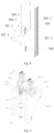
- a side view of the system is shown in Fig. 2 .
- Other structures of the machine tool are from the prior art, which will not be described here.
- first workpiece grabbing structure and the second workpiece grabbing structure each comprise:
- the workpiece clamping machine in this embodiment comprises pneumatic fingers and clamping jaws, and the clamping jaws are installed on the pneumatic fingers.
- the clamping jaws are driven by the pneumatic fingers to open and close to clamp the workpiece.
- four slide blocks are provided, which are respectively fixed at four positions, namely, top, bottom, left and right, in the middle of the cross beam of the gantry machine tool.
- Two grabbing guide rails are provided and fixed between the vertical supporting part and the slide blocks.
- a driving motor of the gantry machine tool drives a portal frame to move to a position above the workpiece through a lead screw and a lead screw nut, and the bracket is lowered under the drive of the hydraulic cylinder, so that the workpiece clamping machine at a lower end of the bracket is lowered to a position where the workpiece is located.
- the workpiece clamping machine opens its clamping jaws through a pneumatic device to clamp the workpiece, then the bracket drives the workpiece clamping machine to lift the workpiece under the drive of the hydraulic cylinder, the workpiece is transferred by the portal frame to be above a target position, the hydraulic cylinder drives the bracket to descend to the target position, and the workpiece clamping machine releases the workpiece to complete the transfer.
- the workpiece transferring device may be driven by the cross beam of the gantry machine tool to transfer the workpiece without moving the workpiece out of the machine tool, thus improving the working efficiency.
- the transferring process is completed by the machine tool, and no separate transferring mechanism is needed, thus saving the labor cost.
- the workpiece transferring device is arranged in the middle of the cross beam of the gantry machine tool, the workpiece transferring device comprises the workpiece clamping machine, the bracket, the slide blocks, the guide rails and the hydraulic cylinder.
- the hydraulic cylinder is fixed in the middle of the cross beam of the gantry machine tool, a hydraulic rod of the hydraulic cylinder is connected with the bracket, the slide blocks are fixed on the cross beam, the guide rails are vertically fixed on two sides of the bracket, and the slide blocks are connected with the guide rails.
- the hydraulic cylinder may drive the bracket to make the bracket move upwards and downwards along the guide rails on the slide blocks.
- the lower end of the bracket is provided with the workpiece clamping machine, which may move along with the cross beam of the gantry machine tool to transfer the workpiece after clamping the workpiece, thus reducing the workpiece transferring time and improving the working efficiency.
- each side rocker comprises a rocker, a ram, a saddle, rocker guide rails, a first slide block, a second slide block and a third slide block
- the rocker guide rails are fixed on one side of the ram
- the rocker is fixed on the other side of the ram
- one ends of the first slide block, the second slide block and the third slide block slide on the guide rails
- the other ends of the first slide block, the second slide block and the third slide block are fixed on a same side of the saddle at equal intervals.
- the rocker of the existing gantry machine tool is installed on a lower end face of the ram, and a distance between an installation face of the rocker and a lowermost pair of slide blocks on the saddle is large, so that the deformation of the ram is large.
- a rocker and ram structure of the invention is shown in Figs. 6 and 7 .
- the rocker is arranged on a fixing table at a front end of the ram, the guide rails are fixed at a rear end of the ram opposite to the fixing table, and the first slide block, the second slide block and the third slide block are fixed on the saddle and slide on the guide rails.
- Fig. 6 A rocker and ram structure of the invention is shown in Figs. 6 and 7 .
- the rocker is arranged on a fixing table at a front end of the ram
- the guide rails are fixed at a rear end of the ram opposite to the fixing table
- the first slide block, the second slide block and the third slide block are fixed on the saddle and slide on the guide rails.
- the fixing table is integrally formed with the ram, and comprises a first fixing plate, a second fixing plate, a third fixing plate and a supporting plate, wherein the first fixing plate and the second fixing plate have the same shape and size, and are arranged parallel to each other and perpendicular to the supporting plate, and the supporting plate is provided with a through hole for fixing the rocker; and the third fixing plate is perpendicular to the first fixing plate, the second fixing plate and the supporting plate, and parallel to a side, where the fixing table is fixed, of the ram, and the first fixing plate, the second fixing plate, the third fixing plate and the supporting plate are integrally formed.
- the fixing table is formed by the combination of a plurality of fixing plates, thus improving the rigidity of the fixing table, so that the rocker may be supported more stably and is unlikely to shake in operation.
- the ram is provided with a fixing table for fixing the rocker, and the fixing table comprises a first fixing plate, a second fixing plate, a third fixing plate and a supporting plate;
- the first fixing plate and the second fixing plate are parallel to each other and perpendicular to the supporting plate, the supporting plate is provided with a through hole for fixing the rocker, and the third fixing plate is perpendicular to the first fixing plate, the second fixing plate and the supporting plate; and the first fixing plate, the second fixing plate, the third fixing plate and the supporting plate are integrally formed, the third fixing plate is parallel to the ram, and the first fixing plate, the second fixing plate and the supporting plate are integrally formed with the ram.
- the fixing table further comprises a first fixing frame, a second fixing frame and a third fixing frame;
- the first fixing frame and the second fixing frame are both parallel to and above the supporting plate, the first fixing frame and the second fixing frame are connected with the ram, and outward edges of the first fixing frame and the second fixing frame are both in a shape matching a radian of a side, close to the ram, of the through hole; and the third fixing frame penetrates through the second fixing frame and intersects with the supporting plate and the first fixing frame, and is perpendicular to the first fixing frame, the second fixing frame and the supporting plate.
- the first fixing frame and the second fixing frame have the same shape and size
- the first fixing frame and the second fixing frame are rectangular and one side is an inward concave arc, and a radian of the arc matches the radian of the side, close to the ram, of the through hole of the supporting plate.
- the first fixing frame and the second fixing frame are parallel to and above the supporting plate, and the second fixing frame is positioned between the supporting plate and the first fixing frame.
- the third fixing frame is rectangular and has a width equal to a distance between the through hole of the supporting plate and the ram.
- the third fixing frame is perpendicular to the first fixing frame, the second fixing frame and the supporting plate.
- the third fixing frame passes through the second fixing frame and intersects with the supporting plate and the first fixing frame.
- the first fixing frame, the second fixing frame and the third fixing frame are all integrally formed with the fixing table.
- the first fixing frame, the second fixing frame and the third fixing frame further stabilize the rocker, strengthen the stability of the rocker, increase the rigidity of the whole structure, and reduce the deformation of the ram.
- the supporting plate of the fixing table and the third slide block have a same height, which is a height of the third slide block when the saddle is located at a top of the guide rails, and is also a height of the rocker fixed by the fixing table. This height makes a distance between the installation face of the rocker and the third slide block on the saddle smaller, so that the deformation of the ram is small in operation and the working efficiency is improved.
- a part, below the fixing table, of the ram is designed as a wedge-shaped structure with thickness a gradually decreasing downwards, so as to reserve enough working space for the rocker.
- the supporting plate is as high as the third slide block when the saddle is located at the top of the guide rails, and the third slide block is located below the first slide block and the second slide block.
- a thickness of the ram below the supporting plate decreases gradually downwards.
- first double-drive screw transmission structure and the second double-drive screw transmission structure each comprise:
- the first motor base and the second motor base in this embodiment are two hollow steel cages with different heights, and the first driving motor and the second driving motor and respectively fixed on upper surfaces of the two hollow steel cages. Edges of the first motor base and the second motor base, except those on upper surfaces corresponding to the lead screw, are provided with flanges extending to opposite sides. As shown in Figs. 9 and 10 , two ends of the lead screw are respectively fixed to the upper support and the lower support through bearings, and the upper support and the lower support are integrally formed with the saddle.
- the first motor base and the second motor base are hollow steel cages with different heights, the first motor base is higher than the second motor base, the first driving motor is fixed on the first motor base, and the second driving motor is fixed on the second motor base.
- Top surfaces of the first motor base and the second motor base are reserved with through holes through which motor shafts of the first driving motor and the second driving motor may pass, and the first motor base and the second motor base are fixed on the saddle by bolts.
- the first driving wheel is connected with the first driving motor, the first driven wheel is connected with a top end of the lead screw, the second driving wheel is connected with the second driving motor, and the second driven wheel is connected with the top end of the lead screw;
- the first driven wheel is arranged above the second driven wheel, the first driving wheel and the first driven wheel are in a same horizontal plane, and the second driving wheel and the second driven wheel are in a same horizontal plane;
- the first synchronous belt is connected with the first driving wheel and the first driven wheel
- the second synchronous belt is connected with the second driving wheel and the second driven wheel, and the first driven wheel and the second driven wheel are connected with the lead screw through expansion sleeves, so that the first driven wheel and the second driven wheel are firmly connected with the lead screw without moving upwards and downwards or rotating along the lead screw under the expansion effect of expansion sleeves.
- the first driving wheel and the second driving wheel respectively drive the first synchronous belt and the second synchronous belt to operate, which further respectively drive the first driven wheel and the second driven wheel to operate, thereby allowing the first driven wheel and the second driven wheel to drive the lead screw to operate.
- the design of a single lead screw reduces a space occupied by a driving device of the machine tool and saves the cost.
- the hollow steel cage design of the motor bases is beneficial to the overhaul and maintenance of the first synchronous belt, the second synchronous belt, the first driving wheel and the second driving wheel.
- the first motor base and the second motor base respectively support the first driving motor and the second driving motor.
- each side of the first motor base and the second motor base is provided with flanges extending to opposite sides, which improves the rigidity and supporting stability of the first motor base and the second motor base, prevents the first driving motor and the second driving motor from vibrating violently during operation and reduces the working efficiency.
- an included angle between the first synchronous belt and the second synchronous belt is 60°-180°.
- the included angle between the first synchronous belt and the second synchronous belt is 60°-180°.
- the angle enables the first driving motor and the second driving motor to better drive the lead screw to work, and reduces a resultant force of pretightening forces of the two belts, thereby reducing a stress on the bearing and prolonging the service life of equipment.
- a distance between the first driven wheel and the second driven wheel is not greater than 50 mm.
- the distance between the first driven wheel and the second driven wheel should not exceed 50 mm.
Landscapes
- Engineering & Computer Science (AREA)
- Mechanical Engineering (AREA)
- Machine Tool Units (AREA)
- Multi-Process Working Machines And Systems (AREA)
- Feeding Of Workpieces (AREA)
- Turning (AREA)
- Automatic Analysis And Handling Materials Therefor (AREA)
- Automobile Manufacture Line, Endless Track Vehicle, Trailer (AREA)
Claims (8)
- Un système d'usinage combiné à portique à double poste permettant le retournement automatique de pièces à travailler, comprenant :une première unité d'usinage à portique mobile (101), une deuxième unité d'usinage à portique mobile (102), une plate-forme de retournement (103), une première table d'assujettissement de pièce à travailler, une deuxième table d'assujettissement de pièce à travailler, un rail-guide et un établi, la plate-forme de retournement étant agencée sur l'établi et positionnée entre la première unité d'usinage à portique et la deuxième unité d'usinage à portique ;la première unité d'usinage à portique mobile comprend une première poutre transversale, une première structure de saisie de pièce à travailler (108), une première structure de transmission à vis double entraînement (106) et une première unité à balancier latéral (104), et la deuxième unité d'usinage à portique mobile comprend une deuxième poutre transversale, une deuxième structure de saisie de pièce à travailler, une deuxième structure de transmission à vis double entraînement et un deuxième balancier latéral ;la première structure de saisie de pièce à travailler est agencée sur un côté, à l'opposé de la deuxième poutre transversale, de la première poutre transversale, la première structure de transmission à vis double entraînement est agencée sur un autre côté de la première poutre transversale, la deuxième structure de saisie de pièce à travailler est agencée sur un côté, à l'opposé de la première poutre transversale, de la deuxième poutre transversale, la deuxième structure de transmission à vis double entraînement est agencée sur un autre côté de la deuxième poutre transversale, la première structure de transmission à vis double entraînement entraîne le premier balancier latéral afin qu'il se meuve vers le haut et vers le bas, et la deuxième structure de transmission à vis double entraînement entraîne le deuxième balancier latéral afin qu'il se meuve vers le haut et vers le bas ;la première structure de saisie de pièce à travailler est utilisée pour saisir une pièce à travailler sur la première table d'assujettissement de pièce à travailler ou la plate-forme de retournement et placer la pièce à travailler sur la plate-forme de retournement ou la première table d'assujettissement de pièce à travailler, la deuxième structure de saisie de pièce à travailler est utilisée pour saisir une pièce à travailler sur la deuxième table d'assujettissement de pièce à travailler ou la plate-forme de retournement et placer la pièce à travailler sur la plate-forme de retournement ou la deuxième table d'assujettissement de pièce à travailler, et la plate-forme de retournement est agencée sur le rail-guide et utilisée pour retourner la pièce à travailler.
- Le système selon la revendication 1, dans lequel la première structure de saisie de pièce à travailler et la deuxième structure de saisie de pièce à travailler comprennent chacune :une machine de serrage de pièce à travailler (201), un support (202), un bloc de glissement (203), des rails-guides de saisie (204) et un vérin hydraulique (205) ;le bloc de glissement est assujetti dans un milieu d'une poutre transversale d'une machine-outil à portique, les rails-guides de saisie sont assujettis sur le support et raccordés au bloc de glissement, le vérin hydraulique est assujetti sur la poutre transversale, une tige hydraulique du vérin hydraulique est raccordée au support, le vérin hydraulique entraîne le support afin qu'il se meuve vers le haut et vers le bas le long du bloc de glissement, et une extrémité inférieure du support est pourvue de la machine de serrage de pièce à travailler ;le support comprend une partie de soutien verticale (202.2) et une partie d'assujettissement transversale (202.1), la partie d'assujettissement transversale a une extrémité raccordée de façon assujettie à une extrémité de dessous de la partie de soutien verticale et une extrémité assujettissant la machine de serrage de pièce à travailler, et la partie d'assujettissement transversale est positionnée sur un côté près de la structure de transmission à vis double entraînement.
- Le système selon la revendication 1, dans lequel chaque dite unité à balancier latéral comprend un balancier (301), un coulisseau (302), une chaise (305), des rails-guides de balancier (303), des premiers groupes de blocs de glissement (304.1), des deuxièmes groupes de blocs de glissement (304.2) et des troisièmes groupes de blocs de glissement (304.3) ;
un côté de la chaise est pourvu d'une rainure de réception, les premiers groupes de blocs de glissement, les deuxièmes groupes de blocs de glissement et les troisièmes groupes de blocs de glissement sont agencés sur deux parois internes de la rainure de réception, le coulisseau est placé dans la rainure de réception, les rails-guides de balancier sont agencés sur des surfaces, correspondant aux deux parois internes de la rainure de réception, du coulisseau, les rails-guides de balancier sont raccordés aux premiers groupes de blocs de glissement, aux deuxièmes groupes de blocs de glissement et aux troisièmes groupes de blocs de glissement, et le balancier est agencé sur un côté, à l'opposé de la chaise, du coulisseau. - Le système selon la revendication 3, dans lequel le coulisseau est pourvu d'une table d'assujettissement pour assujettir le balancier, et la table d'assujettissement comprend une première plaque d'assujettissement (307.1), une deuxième plaque d'assujettissement (307.2), une troisième plaque d'assujettissement et une plaque de soutien (307.3) ;
la première plaque d'assujettissement et la deuxième plaque d'assujettissement sont parallèles l'une à l'autre et perpendiculaires à la plaque de soutien, la plaque de soutien est pourvue d'un trou traversant pour assujettir le balancier, et la troisième plaque d'assujettissement est perpendiculaire à la première plaque d'assujettissement, à la deuxième plaque d'assujettissement et à la plaque de soutien ; et la première plaque d'assujettissement, la deuxième plaque d'assujettissement, la troisième plaque d'assujettissement et la plaque de soutien sont formées d'un seul tenant, la troisième plaque d'assujettissement est parallèle au coulisseau, et la première plaque d'assujettissement, la deuxième plaque d'assujettissement et la plaque de soutien sont formées d'un seul tenant avec le coulisseau. - Le système selon la revendication 4, dans lequel la table d'assujettissement comprend en outre un premier cadre d'assujettissement (309.1), un deuxième cadre d'assujettissement (309.2) et un troisième cadre d'assujettissement (309.3) ;
le premier cadre d'assujettissement et le deuxième cadre d'assujettissement sont tous deux parallèles à la plaque de soutien et au-dessus de celle-ci, le premier cadre d'assujettissement et le deuxième cadre d'assujettissement sont raccordés au coulisseau, et des bords vers l'extérieur du premier cadre d'assujettissement et du deuxième cadre d'assujettissement sont tous deux d'une forme concordant avec un radian d'un côté, près du coulisseau, du trou traversant ; et le troisième cadre d'assujettissement pénètre à travers le deuxième cadre d'assujettissement et croise la plaque de soutien et le premier cadre d'assujettissement, et est perpendiculaire au premier cadre d'assujettissement, au deuxième cadre d'assujettissement et à la plaque de soutien. - Le système selon la revendication 1, dans lequel la première structure de transmission à vis double entraînement et la deuxième structure de transmission à vis double entraînement comprennent chacune :une chaise (401), un premier moteur d'entraînement (411.1), un deuxième moteur d'entraînement (411.2), une première base de moteur, une deuxième base de moteur, une première courroie synchrone (408.1), une deuxième courroie synchrone (408.2), une vis mère (402), une première roue d'entraînement (409.1), une deuxième roue d'entraînement (409.2), une première roue entraînée (410.1) et une deuxième roue entraînée (410.2) ;la vis mère est assujettie sur la chaise par l'intermédiaire d'un élément de soutien supérieur (405) et d'un élément de soutien inférieur (404), la première base de moteur et la deuxième base de moteur sont assujetties sur un dessus de la chaise, le premier moteur d'entraînement et le deuxième moteur d'entraînement sont assujettis respectivement sur la première base de moteur et la deuxième base de moteur, la première roue d'entraînement est raccordée au premier moteur d'entraînement, et la deuxième roue d'entraînement est raccordée au deuxième moteur d'entraînement ; et la première roue entraînée et la deuxième roue entraînée sont toutes deux raccordées à la vis mère, la première courroie synchrone est raccordée à la première roue d'entraînement et à la première roue entraînée, et la deuxième courroie synchrone est raccordée à la deuxième roue d'entraînement et à la deuxième roue entraînée.
- Le système selon la revendication 6, dans lequel un angle inclus entre la première courroie synchrone et la deuxième courroie synchrone fait de 60° à 180°.
- Le système selon la revendication 7, dans lequel une distance entre la première roue entraînée et la deuxième roue entraînée ne fait pas plus de 50 mm.
Applications Claiming Priority (2)
| Application Number | Priority Date | Filing Date | Title |
|---|---|---|---|
| CN201910272780.8A CN109940442B (zh) | 2019-04-04 | 工件自动翻转加工的双工位龙门组合加工系统 | |
| PCT/CN2020/083220 WO2020200308A1 (fr) | 2019-04-04 | 2020-04-03 | Système de traitement combiné à portique à double poste pour retourner et traiter automatiquement des pièces à travailler |
Publications (3)
| Publication Number | Publication Date |
|---|---|
| EP3943238A1 EP3943238A1 (fr) | 2022-01-26 |
| EP3943238A4 EP3943238A4 (fr) | 2022-04-27 |
| EP3943238B1 true EP3943238B1 (fr) | 2023-05-31 |
Family
ID=67013737
Family Applications (1)
| Application Number | Title | Priority Date | Filing Date |
|---|---|---|---|
| EP20784136.2A Active EP3943238B1 (fr) | 2019-04-04 | 2020-04-03 | Système de traitement combiné à portique à double poste pour retourner et traiter automatiquement des pièces à travailler |
Country Status (6)
| Country | Link |
|---|---|
| US (1) | US11897073B2 (fr) |
| EP (1) | EP3943238B1 (fr) |
| JP (1) | JP7239735B2 (fr) |
| KR (1) | KR102585379B1 (fr) |
| ES (1) | ES2948622T3 (fr) |
| WO (1) | WO2020200308A1 (fr) |
Families Citing this family (12)
| Publication number | Priority date | Publication date | Assignee | Title |
|---|---|---|---|---|
| CN113118792A (zh) * | 2021-03-31 | 2021-07-16 | 北京精雕科技集团有限公司 | 一种立卧结合的双工位复合机床 |
| CN113695427B (zh) * | 2021-08-27 | 2023-11-07 | 安徽中佳自动化科技有限公司 | 一种双向折弯机 |
| CN113770788B (zh) * | 2021-10-09 | 2022-07-29 | 意特利(滁州)智能数控科技有限公司 | 一种上料机构及数控机床 |
| CN113909980B (zh) * | 2021-11-16 | 2022-07-19 | 湖南耀岷专用汽车制造有限公司 | 一种汽车钣金加工用翻转夹持装置 |
| KR20230152910A (ko) | 2022-04-28 | 2023-11-06 | (주)아이제이에스 | 공작물 자동 가공 시스템 |
| CN114850947A (zh) * | 2022-06-15 | 2022-08-05 | 深圳市富士杰智能技术有限公司 | 自动翻料数控设备关节机器人 |
| CN115070393A (zh) * | 2022-07-04 | 2022-09-20 | 上海应用技术大学 | 一种自动化翻转防坠落套舱装置 |
| CN116984925B (zh) * | 2023-06-26 | 2023-12-29 | 意特利(滁州)智能数控科技有限公司 | 双工位高效数控机床 |
| CN116786867B (zh) * | 2023-08-28 | 2023-10-31 | 常州市武进广宇花辊机械有限公司 | 一种熔喷板模头喷丝孔的加工装置及加工方法 |
| CN117001043B (zh) * | 2023-09-25 | 2024-01-23 | 河南威猛振动设备股份有限公司 | 一种方舱打孔加工生产线 |
| CN117140131B (zh) * | 2023-10-08 | 2024-03-19 | 意特利(滁州)智能数控科技有限公司 | 双主轴多模数控机床 |
| CN117299979B (zh) * | 2023-11-24 | 2024-03-12 | 宁波合力制动系统有限公司 | 一种调整臂生产装置 |
Family Cites Families (28)
| Publication number | Priority date | Publication date | Assignee | Title |
|---|---|---|---|---|
| JPS58502159A (ja) * | 1981-12-18 | 1983-12-15 | ラルス・インタ−ナショナル・ソシエテ・アノニム・ルクセンブルグ | 2個のモ−タを備えた線形駆動装置 |
| US4926709A (en) * | 1988-05-16 | 1990-05-22 | Gardner James J | Motion transmitting systems for machinery & machine tools |
| DE9007812U1 (de) * | 1990-08-07 | 1997-01-02 | Atg Test Systems Gmbh | Mehrspindelmaschine zum Bohren, Fräsen o.dgl. |
| JP3184838B2 (ja) * | 1991-09-13 | 2001-07-09 | 有限会社北四国エンジニアリング | 石材加工装置とその加工方法 |
| US6138818A (en) * | 1998-11-23 | 2000-10-31 | Green Technologies Inc. | Workpiece inversion system for milling machines |
| ITBO20010134A1 (it) * | 2001-03-13 | 2002-09-13 | Jobs Spa | Macchina utensile |
| US20050084345A1 (en) | 2003-10-17 | 2005-04-21 | Frye Randy C. | Dual motor tapping machine |
| ITMO20050268A1 (it) * | 2005-10-18 | 2007-04-19 | Scm Group Spa | Macchina operatrice per la lavorazione di elementi in legno |
| DE102008032302A1 (de) * | 2008-07-09 | 2010-01-14 | Weinmann Holzbausystemtechnik Gmbh | Vorrichtung zum Fördern eines Werkstücks |
| IT1399150B1 (it) * | 2009-06-23 | 2013-04-11 | Biesse Spa | Macchina per la lavorazione di componenti di legno o simili |
| IT1394376B1 (it) * | 2009-06-23 | 2012-06-15 | Biesse Spa | Macchina per la lavorazione di componenti di legno o simili |
| DE102010004990B4 (de) * | 2010-01-19 | 2012-01-19 | Deckel Maho Seebach Gmbh | Werkzeugmaschine |
| ITBO20100331A1 (it) * | 2010-05-27 | 2011-11-28 | Biesse Spa | Metodo e macchina per la lavorazione di componenti di legno o simili, in particolare componenti per infissi |
| KR101430047B1 (ko) * | 2012-05-10 | 2014-08-21 | 이민지 | 2축 갠트리 로더의 새들 및 이를 적용한 2축 갠트리 로더 |
| KR20140059335A (ko) * | 2012-11-07 | 2014-05-16 | 두산인프라코어 주식회사 | 갠트리 로더를 구비한 공작 기계 |
| CN103600232B (zh) * | 2013-10-23 | 2017-02-08 | 山东智汇专利运营有限公司 | 数控铣、镗复合机床 |
| KR102231352B1 (ko) * | 2014-04-22 | 2021-03-24 | 두산공작기계 주식회사 | 2개의 스핀들을 구비하는 공작기계 |
| KR20150121877A (ko) * | 2014-04-22 | 2015-10-30 | 두산인프라코어 주식회사 | 2개의 스핀들을 구비한 공작기계의 갠트리 로더 |
| DE102014113663A1 (de) * | 2014-09-22 | 2016-03-24 | Broetje-Automation Gmbh | Bearbeitungsanlage für Flugzeugstrukturbauteile |
| TWI586463B (zh) * | 2015-01-06 | 2017-06-11 | Chen Peng-Ren | CNC double spindle drive |
| JP6514028B2 (ja) | 2015-05-15 | 2019-05-15 | 平田機工株式会社 | 割断方法及び割断装置 |
| CN204934696U (zh) * | 2015-08-27 | 2016-01-06 | 邓力凡 | 一种新型单主轴五面体加工数控铣床 |
| CN105946128A (zh) * | 2016-06-29 | 2016-09-21 | 上海日进机床有限公司 | 工件翻转装置及工件线切割设备 |
| CN106624084B (zh) | 2016-09-29 | 2018-10-26 | 宁波德玛智能机械有限公司 | 用于轮毂加工的龙门式双头数控铣床 |
| US10293442B2 (en) * | 2017-07-07 | 2019-05-21 | Baizheng Innovation Technology Co., Ltd. | C-type CNC machine center |
| CN108115421A (zh) * | 2018-01-17 | 2018-06-05 | 珠海市瑞德盛数控科技有限公司 | 一种双工位四轴加工数控高光机 |
| CN110039326A (zh) * | 2019-04-04 | 2019-07-23 | 科德数控股份有限公司 | 一种数控机床的摆头安装结构 |
| CN110039323A (zh) * | 2019-04-04 | 2019-07-23 | 科德数控股份有限公司 | 一种具有工件搬运装置的龙门机床 |
-
2020
- 2020-04-03 US US17/600,920 patent/US11897073B2/en active Active
- 2020-04-03 WO PCT/CN2020/083220 patent/WO2020200308A1/fr unknown
- 2020-04-03 EP EP20784136.2A patent/EP3943238B1/fr active Active
- 2020-04-03 ES ES20784136T patent/ES2948622T3/es active Active
- 2020-04-03 KR KR1020217035316A patent/KR102585379B1/ko active IP Right Grant
- 2020-04-03 JP JP2021558698A patent/JP7239735B2/ja active Active
Also Published As
| Publication number | Publication date |
|---|---|
| US11897073B2 (en) | 2024-02-13 |
| EP3943238A4 (fr) | 2022-04-27 |
| EP3943238A1 (fr) | 2022-01-26 |
| ES2948622T3 (es) | 2023-09-14 |
| WO2020200308A1 (fr) | 2020-10-08 |
| KR102585379B1 (ko) | 2023-10-05 |
| KR20210151858A (ko) | 2021-12-14 |
| US20220193842A1 (en) | 2022-06-23 |
| CN109940442A (zh) | 2019-06-28 |
| JP7239735B2 (ja) | 2023-03-14 |
| JP2022527957A (ja) | 2022-06-07 |
Similar Documents
| Publication | Publication Date | Title |
|---|---|---|
| EP3943238B1 (fr) | Système de traitement combiné à portique à double poste pour retourner et traiter automatiquement des pièces à travailler | |
| EP3943228A1 (fr) | Centre d'usinage horizontal à cinq axes avec changement de palette | |
| CN110355830B (zh) | 一种高效率数控六面钻孔机及其加工方式 | |
| CN100579684C (zh) | 双向移动立式钢筋自动弯曲机 | |
| US8492677B2 (en) | Process for laser cutting a metal plate | |
| US10926373B2 (en) | Honing machine with a machine frame and at least two units arranged on both sides of the machine frame | |
| KR101033289B1 (ko) | 원통형 중량 가공물의 내경을 가공하기 위한 장치 | |
| US4503741A (en) | Bridge type punch press | |
| KR20210119717A (ko) | 배터리팩 마운팅 장치용 프로파일 전용 가공장치 | |
| CN103084931A (zh) | 一种双主轴卧式复合加工中心 | |
| CN211891228U (zh) | 雕铣机的翻转机构 | |
| CN210756663U (zh) | 工件自动翻转加工的双工位龙门组合加工系统 | |
| CN111360571A (zh) | 一种立式轴承座底面加工夹具 | |
| CN214919483U (zh) | 一种钢管数控折弯控制装置 | |
| CN109940442B (zh) | 工件自动翻转加工的双工位龙门组合加工系统 | |
| CN210080971U (zh) | 一种激光切割机交换式双工作台的升降机构 | |
| CN114080295A (zh) | 用于输送工件部分的方法 | |
| CN110125713B (zh) | 长轴上料装置 | |
| CN218192014U (zh) | 一种钢构件多角度冲孔装置 | |
| CN212734980U (zh) | 一种镗床附加工作台 | |
| CN214769418U (zh) | 一种切割装置 | |
| CN219152183U (zh) | 一种用于轴承座端面的加工装置 | |
| CN103252664A (zh) | 一种丝杆轴承座组加工治具及加工工艺 | |
| CN212793030U (zh) | 一种精车机送料结构 | |
| CN203409536U (zh) | 一种丝杆轴承座组加工治具 |
Legal Events
| Date | Code | Title | Description |
|---|---|---|---|
| STAA | Information on the status of an ep patent application or granted ep patent |
Free format text: STATUS: THE INTERNATIONAL PUBLICATION HAS BEEN MADE |
|
| PUAI | Public reference made under article 153(3) epc to a published international application that has entered the european phase |
Free format text: ORIGINAL CODE: 0009012 |
|
| STAA | Information on the status of an ep patent application or granted ep patent |
Free format text: STATUS: REQUEST FOR EXAMINATION WAS MADE |
|
| 17P | Request for examination filed |
Effective date: 20211018 |
|
| AK | Designated contracting states |
Kind code of ref document: A1 Designated state(s): AL AT BE BG CH CY CZ DE DK EE ES FI FR GB GR HR HU IE IS IT LI LT LU LV MC MK MT NL NO PL PT RO RS SE SI SK SM TR |
|
| A4 | Supplementary search report drawn up and despatched |
Effective date: 20220330 |
|
| RIC1 | Information provided on ipc code assigned before grant |
Ipc: B23Q 39/04 20060101ALI20220324BHEP Ipc: B23Q 1/01 20060101ALI20220324BHEP Ipc: B23Q 7/04 20060101AFI20220324BHEP |
|
| DAV | Request for validation of the european patent (deleted) | ||
| DAX | Request for extension of the european patent (deleted) | ||
| INTG | Intention to grant announced |
Effective date: 20230109 |
|
| GRAS | Grant fee paid |
Free format text: ORIGINAL CODE: EPIDOSNIGR3 |
|
| STAA | Information on the status of an ep patent application or granted ep patent |
Free format text: STATUS: GRANT OF PATENT IS INTENDED |
|
| GRAA | (expected) grant |
Free format text: ORIGINAL CODE: 0009210 |
|
| STAA | Information on the status of an ep patent application or granted ep patent |
Free format text: STATUS: THE PATENT HAS BEEN GRANTED |
|
| AK | Designated contracting states |
Kind code of ref document: B1 Designated state(s): AL AT BE BG CH CY CZ DE DK EE ES FI FR GB GR HR HU IE IS IT LI LT LU LV MC MK MT NL NO PL PT RO RS SE SI SK SM TR |
|
| REG | Reference to a national code |
Ref country code: GB Ref legal event code: FG4D Ref country code: CH Ref legal event code: EP |
|
| REG | Reference to a national code |
Ref country code: AT Ref legal event code: REF Ref document number: 1570665 Country of ref document: AT Kind code of ref document: T Effective date: 20230615 Ref country code: DE Ref legal event code: R096 Ref document number: 602020011376 Country of ref document: DE |
|
| REG | Reference to a national code |
Ref country code: IE Ref legal event code: FG4D |
|
| REG | Reference to a national code |
Ref country code: ES Ref legal event code: FG2A Ref document number: 2948622 Country of ref document: ES Kind code of ref document: T3 Effective date: 20230914 |
|
| REG | Reference to a national code |
Ref country code: LT Ref legal event code: MG9D |
|
| REG | Reference to a national code |
Ref country code: NL Ref legal event code: MP Effective date: 20230531 |
|
| PG25 | Lapsed in a contracting state [announced via postgrant information from national office to epo] |
Ref country code: SE Free format text: LAPSE BECAUSE OF FAILURE TO SUBMIT A TRANSLATION OF THE DESCRIPTION OR TO PAY THE FEE WITHIN THE PRESCRIBED TIME-LIMIT Effective date: 20230531 Ref country code: NO Free format text: LAPSE BECAUSE OF FAILURE TO SUBMIT A TRANSLATION OF THE DESCRIPTION OR TO PAY THE FEE WITHIN THE PRESCRIBED TIME-LIMIT Effective date: 20230831 |
|
| PG25 | Lapsed in a contracting state [announced via postgrant information from national office to epo] |
Ref country code: RS Free format text: LAPSE BECAUSE OF FAILURE TO SUBMIT A TRANSLATION OF THE DESCRIPTION OR TO PAY THE FEE WITHIN THE PRESCRIBED TIME-LIMIT Effective date: 20230531 Ref country code: PL Free format text: LAPSE BECAUSE OF FAILURE TO SUBMIT A TRANSLATION OF THE DESCRIPTION OR TO PAY THE FEE WITHIN THE PRESCRIBED TIME-LIMIT Effective date: 20230531 Ref country code: NL Free format text: LAPSE BECAUSE OF FAILURE TO SUBMIT A TRANSLATION OF THE DESCRIPTION OR TO PAY THE FEE WITHIN THE PRESCRIBED TIME-LIMIT Effective date: 20230531 Ref country code: LV Free format text: LAPSE BECAUSE OF FAILURE TO SUBMIT A TRANSLATION OF THE DESCRIPTION OR TO PAY THE FEE WITHIN THE PRESCRIBED TIME-LIMIT Effective date: 20230531 Ref country code: LT Free format text: LAPSE BECAUSE OF FAILURE TO SUBMIT A TRANSLATION OF THE DESCRIPTION OR TO PAY THE FEE WITHIN THE PRESCRIBED TIME-LIMIT Effective date: 20230531 Ref country code: IS Free format text: LAPSE BECAUSE OF FAILURE TO SUBMIT A TRANSLATION OF THE DESCRIPTION OR TO PAY THE FEE WITHIN THE PRESCRIBED TIME-LIMIT Effective date: 20230930 Ref country code: HR Free format text: LAPSE BECAUSE OF FAILURE TO SUBMIT A TRANSLATION OF THE DESCRIPTION OR TO PAY THE FEE WITHIN THE PRESCRIBED TIME-LIMIT Effective date: 20230531 Ref country code: GR Free format text: LAPSE BECAUSE OF FAILURE TO SUBMIT A TRANSLATION OF THE DESCRIPTION OR TO PAY THE FEE WITHIN THE PRESCRIBED TIME-LIMIT Effective date: 20230901 |
|
| PG25 | Lapsed in a contracting state [announced via postgrant information from national office to epo] |
Ref country code: FI Free format text: LAPSE BECAUSE OF FAILURE TO SUBMIT A TRANSLATION OF THE DESCRIPTION OR TO PAY THE FEE WITHIN THE PRESCRIBED TIME-LIMIT Effective date: 20230531 |
|
| PG25 | Lapsed in a contracting state [announced via postgrant information from national office to epo] |
Ref country code: SK Free format text: LAPSE BECAUSE OF FAILURE TO SUBMIT A TRANSLATION OF THE DESCRIPTION OR TO PAY THE FEE WITHIN THE PRESCRIBED TIME-LIMIT Effective date: 20230531 |
|
| PG25 | Lapsed in a contracting state [announced via postgrant information from national office to epo] |
Ref country code: SM Free format text: LAPSE BECAUSE OF FAILURE TO SUBMIT A TRANSLATION OF THE DESCRIPTION OR TO PAY THE FEE WITHIN THE PRESCRIBED TIME-LIMIT Effective date: 20230531 Ref country code: SK Free format text: LAPSE BECAUSE OF FAILURE TO SUBMIT A TRANSLATION OF THE DESCRIPTION OR TO PAY THE FEE WITHIN THE PRESCRIBED TIME-LIMIT Effective date: 20230531 Ref country code: RO Free format text: LAPSE BECAUSE OF FAILURE TO SUBMIT A TRANSLATION OF THE DESCRIPTION OR TO PAY THE FEE WITHIN THE PRESCRIBED TIME-LIMIT Effective date: 20230531 Ref country code: PT Free format text: LAPSE BECAUSE OF FAILURE TO SUBMIT A TRANSLATION OF THE DESCRIPTION OR TO PAY THE FEE WITHIN THE PRESCRIBED TIME-LIMIT Effective date: 20231002 Ref country code: EE Free format text: LAPSE BECAUSE OF FAILURE TO SUBMIT A TRANSLATION OF THE DESCRIPTION OR TO PAY THE FEE WITHIN THE PRESCRIBED TIME-LIMIT Effective date: 20230531 Ref country code: DK Free format text: LAPSE BECAUSE OF FAILURE TO SUBMIT A TRANSLATION OF THE DESCRIPTION OR TO PAY THE FEE WITHIN THE PRESCRIBED TIME-LIMIT Effective date: 20230531 Ref country code: CZ Free format text: LAPSE BECAUSE OF FAILURE TO SUBMIT A TRANSLATION OF THE DESCRIPTION OR TO PAY THE FEE WITHIN THE PRESCRIBED TIME-LIMIT Effective date: 20230531 |
|
| REG | Reference to a national code |
Ref country code: AT Ref legal event code: UEP Ref document number: 1570665 Country of ref document: AT Kind code of ref document: T Effective date: 20230531 |
|
| REG | Reference to a national code |
Ref country code: DE Ref legal event code: R097 Ref document number: 602020011376 Country of ref document: DE |
|
| PLBE | No opposition filed within time limit |
Free format text: ORIGINAL CODE: 0009261 |
|
| STAA | Information on the status of an ep patent application or granted ep patent |
Free format text: STATUS: NO OPPOSITION FILED WITHIN TIME LIMIT |
|
| PG25 | Lapsed in a contracting state [announced via postgrant information from national office to epo] |
Ref country code: SI Free format text: LAPSE BECAUSE OF FAILURE TO SUBMIT A TRANSLATION OF THE DESCRIPTION OR TO PAY THE FEE WITHIN THE PRESCRIBED TIME-LIMIT Effective date: 20230531 |
|
| 26N | No opposition filed |
Effective date: 20240301 |