EP3939777B1 - Vorrichtung zum trennen von miteinander vermischten Stoffen unterschiedlicher Fliessfähigkeit - Google Patents
Vorrichtung zum trennen von miteinander vermischten Stoffen unterschiedlicher Fliessfähigkeit Download PDFInfo
- Publication number
- EP3939777B1 EP3939777B1 EP20210211.7A EP20210211A EP3939777B1 EP 3939777 B1 EP3939777 B1 EP 3939777B1 EP 20210211 A EP20210211 A EP 20210211A EP 3939777 B1 EP3939777 B1 EP 3939777B1
- Authority
- EP
- European Patent Office
- Prior art keywords
- drum
- hollow drum
- scraping element
- element section
- peripheral surface
- Prior art date
- Legal status (The legal status is an assumption and is not a legal conclusion. Google has not performed a legal analysis and makes no representation as to the accuracy of the status listed.)
- Active
Links
Images


Classifications
-
- B—PERFORMING OPERATIONS; TRANSPORTING
- B30—PRESSES
- B30B—PRESSES IN GENERAL
- B30B9/00—Presses specially adapted for particular purposes
- B30B9/02—Presses specially adapted for particular purposes for squeezing-out liquid from liquid-containing material, e.g. juice from fruits, oil from oil-containing material
- B30B9/24—Presses specially adapted for particular purposes for squeezing-out liquid from liquid-containing material, e.g. juice from fruits, oil from oil-containing material using an endless pressing band
- B30B9/241—Presses specially adapted for particular purposes for squeezing-out liquid from liquid-containing material, e.g. juice from fruits, oil from oil-containing material using an endless pressing band co-operating with a drum or roller
-
- A—HUMAN NECESSITIES
- A22—BUTCHERING; MEAT TREATMENT; PROCESSING POULTRY OR FISH
- A22C—PROCESSING MEAT, POULTRY, OR FISH
- A22C17/00—Other devices for processing meat or bones
- A22C17/04—Bone cleaning devices
-
- B—PERFORMING OPERATIONS; TRANSPORTING
- B30—PRESSES
- B30B—PRESSES IN GENERAL
- B30B15/00—Details of, or accessories for, presses; Auxiliary measures in connection with pressing
- B30B15/08—Accessory tools, e.g. knives; Mountings therefor
-
- B—PERFORMING OPERATIONS; TRANSPORTING
- B30—PRESSES
- B30B—PRESSES IN GENERAL
- B30B15/00—Details of, or accessories for, presses; Auxiliary measures in connection with pressing
- B30B15/30—Feeding material to presses
Definitions
- the invention relates to a device designed and configured for separating mixed materials of different flowability, comprising a frame, a hollow drum which is driven in rotation and mounted on the frame and has a perforated outer surface and at least one at least partially open end face, an endless press belt which can be pressed from the outside onto the outer surface by wrapping around part of the circumference of the hollow drum and which is driven in rotation in the conveying direction, a product intake wedge formed by the press belt and the hollow drum for guiding a product flow consisting of pressed material between the hollow drum and the press belt in an inlet region of the product flow into the device, and a device for discharging material to be separated which has been pressed through the perforated outer surface into the hollow drum cavity from the at least partially open end face of the hollow drum.
- the invention further relates to a method for separating mixed materials of different flowability, comprising the steps of: feeding a product stream consisting of material to be pressed into a product intake wedge which is formed by a hollow drum with a perforated outer surface and a press belt which rests on the outside of the hollow drum and wraps around part of the circumference, rotating the hollow drum and/or the press belt to draw the product stream between the hollow drum and the press belt, wherein the more easily flowing components of the product stream are pressed by means of the press belt as material to be separated through the perforation of the outer surface of the hollow drum into the cavity of the hollow drum and are discharged from an at least partially open end face of the hollow drum, while the more difficult-flowing components of the product stream remain on the outside of the outer surface of the hollow drum and are discharged separately.
- Such devices and processes are used in various industrial sectors, but particularly in the food processing industry.
- various materials can be subjected to a separation process.
- the materials to be separated i.e., the material to be pressed or separated, also referred to as "separated," are pressed from the outside against the perforated outer surface M of the hollow drum by means of a pressing element such as a press belt.
- the main product is the heavier-flowing material that collects outside the hollow drum, while the more easily flowing material that is forced through the hollow drum under pressure is only the by-product.
- a device is, for example, US 4 156 384 A known, which has the features of the preamble of claim 1. It relates to a method for dewatering cottage cheese. The whey, together with any other pressed liquids, is pressed through the hollow drum as a free-flowing substance, while the cottage cheese, the product to be extracted, is removed from the outside of the hollow drum. Whey residues adhering to the inside of the hollow drum are removed by means of a scraper.
- the more easily flowing components of the pressed material are pressed under pressure as the main product through the perforation of the outer surface M into the inner cavity of the rotating hollow drum and are discharged, while the more difficult-flowing components of the pressed material remain as a by-product on the outside of the outer surface of the hollow drum and in particular also on or on the surface of the pressing element and are discharged separately.
- the by-products which are also referred to as remaining residues of the pressed material, can in particular adhere to the pressing element, lie on the pressing element, fall off the pressing element and also fall off the outer surface M of the hollow drum or be removed from it, e.g. by means of a scraping element. All residues that are not pressed through the perforation of the outer surface M of the hollow drum are conveyed out of the device via the discharge element as a residual flow and at least partially processed further.
- Substances, materials, or products that differ from one another or whose composition differs due to their differing flow behavior are amenable to separation within the meaning of the invention.
- the possibility and/or necessity of separation of mixed substances of varying fluidity particularly in the production of foodstuffs of animal origin (e.g., separating meat from skin, tendons, bones, etc.), from fruit and vegetables (e.g., separating fruit pulp from peel, stems, seeds, etc.), in the processing of incorrectly packaged foodstuffs (e.g., separating butter or cheese from packaging material), or similar applications.
- Specific application examples include pitting dates or unpacking cheese slices wrapped in foil.
- a product flow is conveyed from a product feed area by a product intake wedge between the pressing element, e.g. the pressing belt, and the hollow drum to a product output area.
- the product intake wedge is formed by the arrangement of the pressing belt to the hollow drum and leads to an (inlet) angle in the inlet area of the product flow into the device.
- the wrap between the pressing belt and the hollow drum creates a pressing area through which the product flow is conveyed.
- Materials with different flow properties are separated by at least partially forcing the more easily flowing materials - for example, meat in the case of animal products - into the hollow drum as separation material, which in the case of animal products consists of small meat threads or strands, and from there removing them.
- the removal takes place via an at least partially open end face of the hollow drum, e.g., on the front side of the device, whereby the front side can also be defined as the back side.
- the more difficult-flowing materials - again in the case of animal products, bones, tendons, skin, etc.
- the material to be separated is removed via an at least partially open end face of the hollow drum, e.g., on the front side of the device, whereby the front side can also be defined as the rear side.
- a scraper element and/or an ejection screw are provided for removing the material to be separated. These serve to scrape the material to be separated from the inner surface of the hollow drum and ensure that the material to be separated leaves the drum.
- Such a device is, for example, from the DE 35 16 623A1
- the separation device disclosed therein has a scraper in the lower region of the drum to guide the accumulated material to be separated out of the drum interior.
- the scraper scrapes off the material to be separated located on the drum interior and guides it out of the drum.
- a removal device in the form of helically wound webs is provided on a support core, which is designed to be inserted into the drum.
- the material to be separated accumulates on the scraper, meaning that the material to be separated accumulates to a significant extent at the scraper, and subsequent product presses on existing product before it leaves the drum.
- This accumulation of the material to be separated on the scraper causes a compression of the material to be separated, which is accompanied by a change in the product structure.
- the material to be separated becomes very compacted and tends to become greasy, which counteracts the discharge process and reduces the product quality for subsequent processes.
- the invention is therefore based on the object of improving the discharge process from the drum interior and of providing a device and a method for separating substances of different flowability, which ensure that the product structure of the separated material is retained and, in particular, that there is no compaction of a previously loose product structure.
- the device for removing the material to be separated comprises a stripping element which is arranged in the upper region of the hollow drum in a position which corresponds at least substantially to the twelve o'clock position and which has at least one stripping element section, wherein the stripping element section is a first stripping element section which is adjacent to the inside of the casing surface and has an angle of inclination ⁇ greater than 90° to the tangential plane of the casing surface opposite to the direction of rotation.
- the phrase "at least substantially corresponds to the twelve o'clock position" within the meaning of the present invention means a position that lies between ten o'clock and two o'clock on a clock, in particular between eleven o'clock and one o'clock, in particular in the range defined by a position between eleven and twelve o'clock on the one hand and twelve and one o'clock on the other.
- the reference point for the position is the first stripping element section. With the front drum edge in the rest position as an imaginary clock face, the reference point for the position is the point at which the first stripping element section meets the drum edge or would meet its extension.
- the stripping element is particularly preferably arranged in a position between eleven and twelve o'clock.
- the material to be separated on the drum inner surface still has an upward velocity component directed against the force of gravity. Detaching the material from the drum inner surface in this range is therefore particularly gentle on the product. Additional acceleration in addition to the already acting force of gravity is avoided, so that the material to be separated falls more gently downwards.
- the "tangential plane of the lateral surface" in the sense of the present invention is the plane that touches the lateral surface in the straight line in which an imaginary extension of the center of the stripping element in width would intersect the lateral surface.
- the angle of inclination ⁇ to the tangential plane of the lateral surface opposite to the direction of rotation is the angle formed with the scraper element in the direction of rotation.
- the angle of inclination to the tangential plane of the The angle formed by the tangential plane of the lateral surface with the scraper element in the direction of rotation.
- the scraper element section By arranging the scraper element section in the upper area of the hollow drum and at an angle to the tangential plane of the shell surface, the material to be separated can be prevented from accumulating at the scraper. Unlike the conventional arrangement of the scraper at an angle of 90° to the tangential plane, the material to be separated is not suddenly stopped by the scraper in the inventive design, but can slowly reduce the speed caused by the rotation of the drum. Even a slight difference compared to conventionally arranged scrapers due to the angled design is sufficient to prevent accumulating. In addition, the arrangement of the scraper in the upper drum area ensures that the material to be separated falls into the lower area of the drum under the influence of gravity.
- the material to be separated which is essentially "planed" from the inside of the drum by the scraper element, retains its loosened product structure because it falls freely and is not compressed or jammed.
- the scraper element according to the invention imparts a twist to the product to be separated, further loosening its structure and preventing crushing.
- the angle of the scraper leads to a gentle initial separation of the incoming product stream. This creates a force in the product stream, which triggers its initial breakup.
- smaller or larger product portions are separated from the product stream and fed to the lower section of the drum by gravity.
- the angle of inclination ⁇ is greater than or equal to 105°, preferably greater than or equal to 110°, and in particular greater than or equal to 115°. Furthermore, the angle of inclination is preferably less than or equal to 135°, preferably less than or equal to 130°, and in particular less than or equal to 125°. Particularly preferably, the angle of inclination lies in a range from 105° to 135°, preferably in a range from 110° to 130°, and in particular in a range from 115° to 125°. Such angles ensure that the material to be separated is detached from the inner surface of the drum particularly efficiently and gently.
- the stripping element has a second stripping element section which, to the first stripping element section, "Having an angle” means that the stripping element sections have an angle ⁇ other than 180° to one another, preferably an angle ⁇ opposite to the direction of rotation between 90° and 180°, in particular between 120° and 160°.
- the second stripping element section supports the process of breaking up the product flow and ensures, on the one hand, that already separated product subsets are safely conveyed towards the lower drum area, and, on the other hand, that partially dissolved but not yet separated areas of the product flow finally separate as product subsets and are then also directed towards the lower drum area.
- the second stripping element section is arranged on the edge of the first stripping element section facing away from the lateral surface and substantially parallel to the direction of the acting gravity.
- substantially parallel in the sense of the present invention means that the second stripping element section is arranged parallel to the direction of the acting gravity or deviating from this direction by an angle of up to 10°, in particular by an angle of up to 5°, in one direction or the other.
- the direction of the acting gravity corresponds to an orientation perpendicular to the tangential plane of the lateral surface at the twelve o'clock position. If the device is installed at an angle, the direction of the acting gravity deviates from the perpendicular to the tangential plane of the lateral surface at the twelve o'clock position by an angle corresponding to the inclination of the device.
- the twelve o'clock position is the position of the drum that is closest to the top of the device in the usual design of the device.
- the combination of the first and second stripping element sections in the aforementioned arrangement and orientation ensures particularly short contact between the material to be separated and the stripping element.
- the duration of contact between the material to be separated and the stripping element is crucial for product quality. The better it is ensured that there is as little permanent sliding contact as possible between the material to be separated and the stripping element, the less the material to be separated is compressed and the looser it remains.
- the present invention not all of the material to be separated pushes past the stripping element and out of the drum. Instead, the material separated by the first stripping element section usually falls loosely downwards at a distance from the second stripping element section.
- the second stripping element section which is arranged parallel to the acting force of gravity, has a certain limiting and guiding function, but does not guide the material to be separated like with conventional strippers, along which the material to be separated is pushed out of the drum.
- the stripping element has a third stripping element section which is arranged on the edge of the second stripping element section facing away from the first stripping element section and has an angle ⁇ of less than 90°, preferably less than 75°, in particular less than 50°, to the tangential plane of the lateral surface in the direction of rotation.
- This third stripping element section ensures that partial product quantities which are thrown against the deflection element in the lower drum region due to their own dynamics during the swirling process are guided downwards with as little adhesion as possible.
- the third stripping element section can be inclined in the direction of the drum axis. In particular, the end of the third stripping element section pointing towards the rear end face can be higher than the end pointing towards the front.
- the length of the second scraper element section is preferably at least twice, preferably at least three times, and in particular at least four times the length of the first and/or third scraper element sections.
- the second scraper element section which is aligned parallel to gravity, is thus the largest of the three sections. It has been shown that for the first scraper element section, even a relatively small expansion in the radial direction is sufficient to achieve the desired effect.
- the length of the first scraper element section is preferably 0.1 to 0.5 times, in particular 0.2 to 0.4 times, the drum radius.
- the orientation of the stripping element in relation to the drum axis there are various variants for the orientation of the stripping element in relation to the drum axis.
- an arrangement with a certain angle was preferred, such that the front end of the stripping element was arranged further in the direction of rotation than the end facing the rear of the drum. This supported and facilitated the forward removal of the material to be separated from the drum.
- the stripping element of the present invention is particularly preferably arranged parallel to the drum axis. In this way, the separated and downwardly directed product portions are not guided directly towards the front-end drum outlet, but essentially vertically downwards.
- the continuous rotation of the drum subsequently imparts a swirling spin to the product portions over a period lasting several drum revolutions, which has a further beneficial effect on the consistency of the material to be separated.
- the product fractions are subjected to such gentle agitation during the swirling process that a loose, crumbly internal product structure is created.
- the contact time of the product fractions with the inner surface of the drum shell is significantly reduced, so that sliding friction between the product being separated and the mechanical components is reduced to a minimum even during this phase.
- the separated material removed from the hollow drum by the scraper element can fall onto any conveyor element for further processing or packaging.
- the scraper element is preferably made of metal, especially stainless steel.
- the latter meets the special requirements placed on materials used in food processing. However, ceramic materials can also be used.
- a removable lip is attached to the end of the first scraper element section facing the lateral surface M. This makes it possible to separately replace the area of the scraper element that is subject to the greatest wear without replacing the entire scraper element.
- the lip can, in particular, be made of the same material as the scraper element, preferably stainless steel. It is also possible for the lip to be made of a different material. Preferred materials here are plastics or rubber.
- the scraper element is arranged on a support that projects into the cavity of the hollow drum.
- This support can project into the drum from the front or the back.
- the drum is closed at the back, so that the support preferably projects into the drum from the front.
- the scraper element is arranged on a cross member that is preferably detachably attached to the frame. In this way, the scraper element projects through the at least partially open front side into the hollow drum.
- the scraper element is very easy to remove from the drum, making the entire drum area easily accessible, for example if it needs to be cleaned.
- the drum jacket has a certain amount of play during the rotational movement. The above-mentioned distances ensure that the stripping element does not hit the drum and damage it, despite a certain amount of play in the drum. Furthermore, it is desirable that the material to be separated completes at least one revolution in the drum before it is scraped off. This applies in particular if, during the separation process cooled, as this ensures particularly effective cooling of the material to be separated. A certain distance between the first scraper element section and the drum shell is therefore desirable. The maximum distance is preferably 5 mm to meet occupational safety requirements.
- the scraper element and the special turbulence it creates in the material to be separated ensure that this cooling reaches the entire material to be separated, including the interior, as a particularly thorough mixing is achieved without the material being crushed or compacted.
- the device according to the invention therefore makes it possible to obtain particularly well-cooled material to be separated that simultaneously has a loose structure.
- a stripping element for a device as described above is designed and constructed for attachment in the upper region of the hollow drum, in particular in a position that at least substantially corresponds to the twelve o'clock position, and at an angle of inclination to the tangential plane of the lateral surface of the hollow drum counter to the direction of rotation of greater than 90°.
- the stripping element is formed from at least two stripping element sections that are at an angle to one another.
- the stripping element has three stripping element sections, each of which is at an angle to one another such that, in side view, the stripping element as a whole—depending on the direction of rotation of the drum—has the shape of a stylized "S" or a stylized question mark.
- the object is further achieved by a method with the steps mentioned at the outset, in which the material to be separated, which has been pressed into the cavity of the hollow drum through the perforated shell surface M, is stripped from the inner surface of the hollow drum in the upper region of the hollow drum in a position which corresponds at least substantially to the twelve o'clock position by means of a stripper with a first stripping element section, wherein the first stripping element section is adjacent to the inner side of the shell surface and has an angle of inclination ( ⁇ ) of greater than 90° to the tangential plane of the shell surface opposite to the direction of rotation.
- ⁇ angle of inclination
- the method according to the invention makes it possible to obtain a separated material with a granular and loose structure, thus significantly improving the quality of the separated material.
- the material to be separated is stripped by means of a stripper with a first stripping element section, which is adjacent to the inner side of the lateral surface and forms an angle ⁇ greater than 105°, preferably greater than 110°, in particular greater than 115°, to the tangential plane of the lateral surface opposite to the direction of rotation. Stripping in this manner leads to a particularly gentle initial dissolution of the incoming product stream.
- partial product quantities are already separated from the product stream by the stripping effected in this manner and are fed to the lower region of the drum under the support of gravity.
- the method according to the invention can prevent the material to be separated from accumulating at the scraper. Because the first scraper element section has an angle of > 90° to the tangential plane of the outer surface opposite to the direction of rotation, the material to be separated is not suddenly stopped by the scraper in the inventive design, but can slowly reduce the speed caused by the rotation of the drum. Even a slight difference compared to conventionally arranged scrapers due to the angle is sufficient to prevent accumulating. In addition, the arrangement of the scraper in the upper drum area ensures that the material to be separated falls into the lower area of the drum under the influence of gravity.
- the material to be separated which is essentially "planed" from the inside of the drum by the scraper element, retains its loosened product structure because it falls freely and is not compressed or jammed. Furthermore, the scraper element according to the invention imparts a twist to the product to be separated, giving it a very loose structure and preventing crushing. The angle of the scraper leads to a gentle initial separation of the incoming product stream. This creates a force in the product stream, which triggers its initial breakup. Depending on the type of product to be processed, smaller or larger product portions are separated from the product stream and fed to the lower section of the drum by gravity.
- the method is carried out with a device having at least one feature as set out in claims 1 to 14 and/or as described in more detail above.
- the method according to the invention enables low-contact detachment of the material to be separated from the inner surface of the drum, minimizing the contact time of the material to be separated with the scraper element.
- the material to be separated is not pushed along the scraper to be removed from the drum. Instead, the material to be separated is scraped off and further loosened by falling. Supported by the rotating movement of the drum, the material to be separated is guided out of the drum.
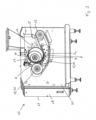
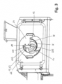
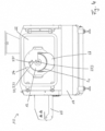
- the device shown in the drawing is used for separating meat on the one hand and bones, bone remnants, tendons, cartilage and the like on the other hand and has a number of preferred features. Other embodiments, which have fewer or different features, are not explicitly shown.
- the device can also be used in the same way for separating, for example, fruit pulp from seeds or for separating any other mixed substances of different flowability.
- the device 10 shown is designed and configured to separate mixed substances of different flowability.
- the device 10 comprises a frame 11, a hollow drum 12 which is driven in rotation and mounted on the frame 11 and has a perforated outer surface M and at least one at least partially open end face S V , S H , an endless press belt 13 which can be pressed from the outside onto the outer surface by wrapping around part of the circumference of the hollow drum 12 and which is driven in rotation, a product intake wedge 14 formed by the press belt 13 and the hollow drum 12 for guiding a product flow consisting of pressed material between the hollow drum 12 and the press belt 13 in an inlet area E of the product flow into the device 10, a support device 15 for the press belt 13 with at least one support element 16 which is arranged on the side of the press belt 13 opposite the hollow drum 12, and a device 17 for discharging through the perforated outer surface M into the cavity H of the hollow drum 12 pressed material to be separated from the at least partially open front side S V , S H of the hollow drum 12.
- the device 17 for removing the separated material from the hollow drum 12 can be an integral part of the device or designed as a separate component.
- the front side S V of the hollow drum 12 facing the front is open, while the opposite end S H is preferably closed.
- the front and rear sides can also be interchanged.
- the frame 11 can, for example, be a closed or at least partially closed housing or a profile construction or the like. Preferably, the housing is substantially closed on all sides.
- the drive unit (not shown) for the hollow drum 12 and/or the press belt 13 is arranged on or in the frame 11.
- the drive unit can comprise a common drive or separate drive means.
- the axis of rotation R of the hollow drum 12 runs transversely to the conveying direction F of the conveyor belt 13.
- bores/openings are formed, which can be arranged in different patterns and allow the passage of parts of the product stream, in particular the more easily flowing, soft and squeezable parts, into the interior of the hollow drum 12.
- the hollow drum 12 is preferably provided with the openings across its entire depth or width, which forms the working area.
- the press belt 13 is preferably made of an elastic material, e.g., rubber, polyurethane, or the like, and is guided around a plurality of deflection elements 19.
- the deflection element 19, which is positioned behind the hollow drum 12 in the conveying direction F is designed as a drive roller 20 to pull the press belt 13, and thus the product stream, past the hollow drum 12.
- the drive roller 20 is simultaneously designed and configured as a pressure roller and/or tensioning roller for the press belt 13.
- the drive roller 20 is adjustable.
- the conveying of the product stream in the conveying direction F can be further assisted by the hollow drum 12's own drive.
- scraping elements can be arranged in the inlet area E, i.e. above the product intake wedge 14, and/or in the outlet area A, i.e. in the conveying direction F behind the hollow drum 12, which is also referred to as a perforated drum.
- These scraping elements can be rigid, i.e. with a fixed distance to the hollow drum 12 or, more precisely, to the outer surface M, or variably controllable, i.e., with a variable distance to the hollow drum 12 or, more precisely, to the outer surface M.
- the device 10 can also comprise a (not shown) discharge conveyor belt in order to remove the difficult-to-flow components remaining on the outside of the press belt 13 and separated from the product stream from the press belt 13. In the Fig. 4 In the embodiment shown, the discharge conveyor belt projects beyond the housing 18 and is protected by a cover 25.
- the hollow drum 12 and the press belt 13 can be driven at the same speed.
- the hollow drum 12 and the press belt 13 can also be driven at different speeds.
- the speed difference can be controlled and/or regulated by means of a control and/or regulating device.
- the support device 15 can be a support chain, a support belt, or a roller conveyor.
- the frame 11 is designed as a housing 18 which comprises a closed working chamber 21 which accommodates at least the hollow drum 12, the press belt 13 and the support device 15 and which has an openable and closable flap 22 on at least one side, which covers the working chamber 21 with the exception of the at least partially open end face SV of the hollow drum 12.
- the flap 22 can represent a front flap of the housing 18. In the closed state, the front flap enables the working chamber 21 to be sealed off from the environment. In the open state, when not in operation, accessibility for cleaning and/or maintenance purposes is ensured.
- the housing 18 can also have other closable openings and access points at other positions.
- the material to be separated which has been pressed through the outer surface M, is removed by means of the removal device 17 in the form of a stripping element 23 in conjunction with the rotation of the hollow drum 12 and, if necessary, by means of a subsequent removal element 27, from which the material to be separated can fall into a trough (not shown) or onto a conveyor belt (also not shown).
- the stripping element 23 is shown, which is detachably attached to the cross member 24.
- the stripping element 23 is arranged in a position that essentially corresponds to the twelve o'clock position 28, a position shortly before twelve o'clock, in the upper region of the hollow drum 12.
- the stripping element 23 has three stripping element sections 231, 232, 233.
- the first stripping element section 231 is arranged adjacent to the inner side of the lateral surface M and has an inclination angle ⁇ of approximately 115° to the tangential plane of the lateral surface, opposite to the direction of rotation.
- the first scraper element section 231 scrapes the material to be separated from the inside of the drum when it has completed at least one partial rotation in the hollow drum 12.
- the material to be separated is gently lifted from the outer surface M and falls under the influence of gravity. into the lower region of the hollow drum 12, from where it moves toward the open end face SV due to the rotation of the hollow drum 12. Since the separated material does not accumulate at the stripping element 23 in this way, it retains its loosened product structure.
- the discharged separated material can, for example, fall onto a discharge chute 27 or the like, which can optionally be cooled and is connected to a corresponding device for this purpose.
- a second scraper element section 232 is arranged on the edge of the first scraper element section 231 facing away from the lateral surface M, specifically at an angle ⁇ of approximately 150° to the first scraper element section 231.
- the second scraper element section is arranged substantially parallel to the acting force of gravity and perpendicular to the tangential plane of the lateral surface M in the twelve o'clock position.
- a third stripping element section 233 is arranged on the edge of the second stripping element section 232 facing away from the first stripping element section 231.
- This third stripping element section 233 forms an angle ⁇ of approximately 45° to the tangential plane of the lateral surface M in the direction of rotation U.
- the stripping element 23 is arranged parallel to the drum axis R and has the shape of a stylized question mark.
- the total extension of the stripping element 23 from the inside of the lateral surface M in radial extension corresponds to the drum radius.
- the length of the second stripping element section 232 is approximately 5 times the length of the first stripping element section 231 and approximately 6 times the length of the second stripping element section 233.
- the edge of the stripping element 23 facing the lateral surface M is spaced 2 mm from the lateral surface.
- the third scraper element section 233 is inclined in the direction of the drum axis such that the end of the third scraper element section 233 pointing towards the rear end face SH of the hollow drum 12 is higher than the end pointing forward.
- a product stream consisting of pressed material is fed into a product intake wedge 14, which is formed by a hollow drum 12 with a perforated outer surface M and a press belt 13, which is guided from the outside. is fed to the hollow drum 12, wrapping around a part of the circumference.
- the hollow drum 12 and the press belt 13 are driven in a rotating manner to draw the product flow between the hollow drum 12 and the press belt 13.
- the hollow drum 12 is driven clockwise, while the drive roller 20 for the press belt (in the view according to the Figure 2 (see) is driven counterclockwise, so that the hollow drum 12 and the press belt 13 have the same conveying direction F in the area of the wrap, i.e. in the pressing area P, whereby the speeds can be the same or different from one another.
- the more easily flowing components of the product flow are pressed by means of the press belt 13 as separation material through the perforation of the outer surface M of the hollow drum 12 into the inner cavity H of the hollow drum 12 and are discharged from an at least partially open end face SV and/or SH of the hollow drum 12, while the more difficult-flowing components of the product flow remain on the outside of the outer surface M of the hollow drum 12 and are discharged separately.
- the press belt 13 is supported on the side of the press belt 13 opposite the hollow drum 12 by a support device 15 comprising at least one support element 16.
- the first stripping element section 231 of the stripping element 23 strips the material to be separated, which has been pressed through the perforated outer surface M into the cavity H of the hollow drum 12, from the inner surface of the hollow drum 12 in the upper region of the hollow drum 12 in a position just before twelve o'clock.
- the stripping is carried out in a very product-friendly manner due to the angled arrangement of the first stripping element section 231.
- the existing structure of the material to be separated is retained and is not compacted.
- the material to be separated falls under the influence of gravity into the lower region of the hollow drum 12, where it is given a spin by the stripping element according to the invention, which supports the maintenance of a loose structure.
- the stripping element 23 is arranged parallel to the drum axis R, the separated and downwardly directed product portions are not directed directly towards the open end face SV of the hollow drum 12, but are guided essentially vertically downwards.
- the continuous rotation of the hollow drum 12 subsequently imparts to the product portions a This creates a swirling swirl over a longer period of time, which further improves the consistency of the product being separated. This also significantly reduces the contact time of the product portions with the inner surface of the drum shell, thus minimizing sliding friction between the product being separated and the mechanical components.
- the material to be separated Due to the rotation of the hollow drum 12, the material to be separated is moved in the direction of its open end face SV and in this way leaves the hollow drum via the discharge element 27, for example into a cooled tub (not shown) for transport or further processing.
Landscapes
- Engineering & Computer Science (AREA)
- Mechanical Engineering (AREA)
- Life Sciences & Earth Sciences (AREA)
- Wood Science & Technology (AREA)
- Zoology (AREA)
- Food Science & Technology (AREA)
- Combined Means For Separation Of Solids (AREA)
- Extraction Or Liquid Replacement (AREA)
- Meat, Egg Or Seafood Products (AREA)
- Apparatuses For Bulk Treatment Of Fruits And Vegetables And Apparatuses For Preparing Feeds (AREA)
Description
- Die Erfindung betrifft eine Vorrichtung, ausgebildet und eingerichtet zum Trennen von miteinander vermischten Stoffen unterschiedlicher Fließfähigkeit, umfassend ein Rahmengestell, eine umlaufend angetriebene und am Rahmengstell gelagerte Hohltrommel mit perforierter Mantelfläche und mindestens einer mindestens teilweise offenen Stirnseite, ein von außen an die Mantelfläche unter Umschlingung eines Teils des Umfangs der Hohltrommel anpressbares, endloses Pressband, das umlaufend in Förderrichtung angetrieben ist, einen durch Pressband und Hohltrommel gebildeten Produkt-Einzugskeil zum Leiten eines aus Pressgut bestehenden Produktstroms zwischen die Hohltrommel und das Pressband in einem Einlaufbereich des Produktstroms in die Vorrichtung sowie eine Einrichtung zum Abführen von durch die perforierte Mantelfläche in den Hohlraum der Hohltrommel gepresstem Separiergut aus der mindestens teilweise offenen Stirnseite der Hohltrommel.
- Die Erfindung betrifft weiterhin ein Verfahren zum Trennen von miteinander vermischten Stoffen unterschiedlicher Fließfähigkeit, umfassend die Schritte: Zuführen eines aus Pressgut bestehenden Produktstroms in einen Produkt-Einzugskeil, der durch eine Hohltrommel mit perforierter Mantelfläche und ein Pressband, das von außen an der Hohltrommel unter Umschlingung eines Teils des Umfangs anliegt, gebildet ist, umlaufendes Antreiben der Hohltrommel und/oder des Pressbandes zum Einziehen des Produktstroms zwischen die Hohltrommel und das Pressband, wobei die leichter fließenden Bestandteile des Produktstroms mittels des Pressbandes als Separiergut durch die Perforation der Mantelfläche der Hohltrommel in den Hohlraum der Hohltrommel gepresst und aus einer mindestens teilweise offenen Stirnseite der Hohltrommel abgeführt werden, während die schwerer fließenden Bestandteile des Produktstroms außen auf der Mantelfläche der Hohltrommel verbleiben und separat abgegeben werden.
- Solche Vorrichtungen und Verfahren kommen in verschiedenen Industriebereichen, insbesondere jedoch in der lebensmittelverarbeitenden Industrie zum Einsatz. Mit den zuvor beschriebenen Vorrichtungen, die auch als Press-Trennmaschinen oder Separatoren bezeichnet werden, lassen sich verschiedenartige Stoffe einem Separierprozess unterziehen. Dazu werden die zu trennenden Stoffe, also das Pressgut bzw. Trenngut, das auch als Separat bezeichnet wird, von außen mittels eines Presselementes wie eines Pressbandes gegen die perforierte Mantelfläche M der Hohltrommel gedrückt.
- Dabei gibt es zwei Varianten. Bei einer Art der Vorrichtung ist das Hauptprodukt der schwerer fließende Stoff, der sich außerhalb der Hohltrommel sammelt, während der leichter fließende Stoff, der unter Druck durch die Hohltrommel gedrückt wird, nur das Nebenprodukt ist. Eine solche Vorrichtung ist z. B. aus der
US 4 156 384 A bekannt, welche die Merkmale des Oberbegriffs des Anspruchs 1 zeigt. Sie betrifft ein Verfahren zum Entwässern von Hüttenkäse. Dabei wird die Molke zusammen mit etwaigen anderen abgepressten Flüssigkeiten als leichter fließender Stoff durch die Hohltrommel gedrückt, während der Hüttenkäse als zu gewinnendes Produkt außen von der Hohltrommel abgenommen wird. Innen an der Hohltrommel haftende Molkereste werden mittels eines Abschabers abgenommen. - Bei der anderen Variante werden unter dem Druck die leichter fließenden Bestandteile des Pressguts als Hauptprodukt durch die Perforation der Mantelfläche M in den inneren Hohlraum der rotierenden Hohltrommel gepresst und abgeführt, während die schwerer fließenden Bestandteile des Pressgutes als Nebenprodukt außen auf der Mantelfläche der Hohltrommel und insbesondere auch an oder auf der Oberfläche des Presselementes verbleiben und separat abgegeben werden. Die Nebenprodukte, die auch als verbleibende Reste des Pressguts bezeichnet werden, können insbesondere am Presselement haften, auf dem Presselement liegen, vom Presselement abfallen und auch von der äußeren Mantelfläche M der Hohltrommel abfallen oder von dieser z.B. mittels eines Abschabelementes gelöst werden. Alle Reste, die nicht durch die Perforation der Mantelfläche M der Hohltrommel gepresst werden, werden über das Abführelement als Reststrom aus der Vorrichtung gefördert und mindestens teilweise weiterverarbeitet.
- Einer Trennung im Sinne der Erfindung zugänglich sind Stoffe, Materialien bzw. Produkte, die sich bzw. deren Zusammensetzung sich durch ihr voneinander abweichendes Fließverhalten unterscheiden. Die Möglichkeit und/oder Notwendigkeit der Trennung von miteinander vermischten Stoffen unterschiedlicher Fließfähigkeit besteht insbesondere bei der Produktion von Lebensmitteln aus tierischem Ursprung (etwa der Abtrennung des Fleisches von der Haut, Sehnen, Knochen bzw. Gräten etc.), aus Obst und Gemüse (etwa der Abtrennung des Fruchtfleisches von Schale, Stielen, Kernen bzw. Steinen etc.), bei der Aufarbeitung von fehlverpackten Lebensmitteln (etwa der Abtrennung von Butter oder Käse vom Verpackungsmaterial) oder dergleichen. Konkrete Anwendungsbeispiele sind z.B. das Entkernen von Datteln oder das Entpacken von in Folie verpackten Käsescheiben.
- Beim Verwerten, Entkernen oder Entpacken oder jedem anderen entsprechenden Separieren wird ein Produktstrom ausgehend von einem Produktzuführbereich mit einem Produkt-Einzugskeil zwischen dem Presselement, also z.B. dem Pressband, und der Hohltrommel hindurch zu einem Produktausgabebereich gefördert. Der Produkt-Einzugskeil wird durch die Anordnung von Pressband zu Hohltrommel gebildet und führt im Einlaufbereich des Produktstroms in die Vorrichtung zu einem (Einlauf-) Winkel. Durch den umlaufenden Antrieb der Hohltrommel und/oder den umlaufenden Antrieb des Pressbandes wird der Produktstrom im Einlaufbereich in Förderrichtung F zwischen die Hohltrommel und das Pressband eingezogen, so dass zwischen dem Pressband und der Hohltrommel ein (mit Produktstrom gefüllter) Abstand/Spalt entsteht. Hinter dem Produkteinzugskeil (bezogen auf die Förderrichtung des Produktstroms) ergibt sich zwischen dem Pressband und der Hohltrommel durch die Umschlingung ein Pressbereich, durch den der Produktstrom gefördert wird. Dabei werden die Stoffe unterschiedlicher Fließfähigkeit getrennt, indem die leichter fließenden Stoffe - am Beispiel der Verarbeitung der Produkte aus tierischem Ursprung das Fleisch - mindestens teilweise als Separiergut, das am Beispiel der Produkte aus tierischem Ursprung aus kleinen Fleischfäden bzw. kleinen Fleischsträngen besteht, in die Hohltrommel gedrückt und von dort abgeführt werden. Das Abführen erfolgt über eine mindestens teilweise geöffnete Stirnseite der Hohltrommel z.B. auf der Vorderseite der Vorrichtung, wobei die Vorderseite auch als Rückseite definiert werden kann. Die schwerer fließenden Stoffe - wiederum am Beispiel der Produkte aus tierischem Ursprung die Knochen, Sehnen, Haut etc. - werden als Nebenprodukte in Förderrichtung F des Produktstroms hinter der Hohltrommel im Produktausgabebereich gesammelt und abgeführt. Der durch die perforierte Mantelfläche M ins Innere der Hohltrommel, also in den Hohlraum, gedrückte Anteil des Produktstroms wird als Separiergut abgeführt und zur Weiterverarbeitung geleitet. Allerdings haftet der nicht durch die perforierte Mantelfläche M ins Innere der Hohltrommel gedrückte Reststrom des Produktstroms einschließlich der schwerer fließenden Bestandteile üblicherweise mindestens teilweise außen an der Mantelfläche der Hohltrommel. Dieser außen an der Hohltrommel anhaftende Reststrom kann z.B. durch Abschabmittel gelöst werden.
- Das Abführen des Separierguts erfolgt über eine mindestens teilweise geöffnete Stirnseite der Hohltrommel z.B. auf der Vorderseite der Vorrichtung, wobei die Vorderseite auch als Rückseite definiert werden kann. Üblicherweise ist zum Abführen des Separierguts ein Abstreifelement und/oder eine Auswurfschnecke vorgesehen. Diese dienen dazu, dass Separiergut von der Innenfläche der Hohltrommel abzustreifen und sicherzustellen, dass das Separiergut die Trommel auch verlässt.
- Eine solche Vorrichtung ist zum Beispiel aus der
DE 35 16 623A1 bekannt. Die dort offenbarte Separiervorrichtung weist einen Abstreifer im unteren Bereich der Trommel auf, um das angesammelte Separiergut aus dem Trommelinneren zu leiten. Der Abstreifer streift das am Trommelinneren befindliche Separiergut ab und führt dieses aus der Trommel heraus. Um diesen Vorgang zu unterstützen, ist es bekannt, den Abstreifer in einem Winkel zur Trommelachse anzuordnen. In Verbindung mit der Rotationsbewegung der Trommel wird bewirkt, dass das Separiergut vom hinteren Bereich der Trommel zur geöffneten Stirnseite der Trommel bewegt wird und die Trommel verlässt. - Auch die
DE 41 16 476 A1 offenbart eine solche Vorrichtung. Hier ist eine Ausräumeinrichtung in Form von schraubenförmig gewundenen Stegen an einem Tragkern vorgesehen, die in die Trommel einschiebbar ausgebildet ist. - Bei einem herkömmlichen Abstreifer kommt es zu einem Auflaufen des Separierguts am Abstreifer, d. h. das Separiergut staut sich in relevantem Maße am Abstreifer, und nachfolgendes Produkt drückt auf schon vorhandenes Produkt, bevor es die Trommel verlässt. Durch dieses Auflaufen des Separierguts am Abstreifer kommt es zu einer Komprimierung des Separierguts, was mit einer Veränderung der Produktstruktur einhergeht. Das Separiergut wird sehr stark kompaktiert und neigt dazu, schmierig zu werden, was dem Ableitprozess entgegenwirkt und die Produktqualität für nachfolgende Prozesse mindert.
- Der Erfindung liegt somit die Aufgabe zugrunde, den Ableitprozess aus dem Trommelinneren zu verbessern und eine Vorrichtung sowie ein Verfahren zum Trennen von Stoffen unterschiedlicher Fließfähigkeit zur Verfügung zu stellen, die dafür sorgen, dass die Produktstruktur des Separierguts erhalten bleibt und insbesondere keine Kompaktierung einer zuvor lockeren Produktstruktur erfolgt.
- Diese Aufgabe wird erfindungsgemäß mit einer Vorrichtung der eingangs genannten Art dadurch gelöst, dass die Einrichtung zum Abführen des Separierguts ein Abstreifelement umfasst, das im oberen Bereich der Hohltrommel in einer Position, die mindestens im Wesentlichen der Zwölf-Uhr-Position entspricht, angeordnet ist und das mindestens einen Abstreifelementabschnitt aufweist, wobei der Abstreifelementabschnitt ein erster Abstreifelementabschnitt ist, der der Innenseite der Mantelfläche benachbart ist und zu der Tangentialebene der Mantelfläche entgegen der Umdrehungsrichtung einen Neigungswinkel α größer als 90° aufweist.
- Dabei bedeutet die Formulierung "mindestens im Wesentlichen der Zwölf-Uhr-Position entspricht" im Sinne der vorliegenden Erfindung eine Position, die auf einer Uhr zwischen zehn Uhr und zwei Uhr liegt, insbesondere zwischen elf Uhr und ein Uhr liegt, insbesondere in dem Bereich der durch eine Stellung zwischen elf und zwölf Uhr einerseits und zwölf und ein Uhr andererseits, definiert ist. Referenz für die Stellung ist dabei der erste Abstreifelementabschnitt. Mit dem vorderen Trommelrand in Ruhestellung als imaginäres Ziffernblatt ist der Referenzpunkt für die Stellung der Punkt, an dem der erste Abstreifelementabschnitt auf den Trommelrand trifft bzw. in seiner Verlängerung treffen würde. Besonders bevorzugt ist das Abstreifelement in einer Position zwischen elf und zwölf Uhr angeordnet. In diesem Bereich weist das Separiergut an der Trommelinnenfläche noch eine aufwärts, gegen die Schwerkraft gerichtete Geschwindigkeitskomponente auf. Ein Ablösen des Separierguts von der Trommelinnenfläche in diesem Bereich ist dadurch besonders produktschonend. Eine zusätzliche Beschleunigung neben der ohnehin wirkenden Schwerkraft wird vermieden, so dass das Separiergut sanfter nach unten fällt.
- Die Tangentialebene der Mantelfläche" im Sinne der vorliegenden Erfindung ist die Ebene, die die Mantelfläche in der Geraden berührt, in der eine gedachte Verlängerung der Mitte des Abstreifelements in Breitenausdehnung die Mantelfläche schneiden würde.
- Der Neigungswinkel α zur Tangentialebene der Mantelfläche entgegen der Umdrehungsrichtung ist der Winkel, der in Umdrehungsrichtung vor dem Abstreifelement mit diesem gebildet wird. Umgekehrt ist der Neigungswinkel zur Tangentialebene der Mantelfläche in Umdrehungsrichtung der Winkel, der in Umdrehungsrichtung hinter dem Abstreifelement von der Tangentialebene der Mantelfläche mit diesem gebildet wird.
- Durch die Anordnung des Abstreifelementabschnitts im oberen Bereich der Hohltrommel und in einem Winkel zur Tangentialebene der Mantelfläche kann ein Stauen des Separierguts am Abstreifer vermieden werden. Anders als bei der herkömmlichen Anordnung des Abstreifers in einem Winkel von 90° zur Tangentialebene wird das Separiergut in der erfindungsgemäßen Ausbildung durch den Abstreifer nicht plötzlich gestoppt, sondern kann die durch die Drehung der Trommel hervorgerufene Geschwindigkeit verlangsamt abbauen. Selbst ein geringer Unterschied zu herkömmlich angeordneten Abstreifern durch Abwinklung ist bereits ausreichend, um ein Aufstauen zu verhindern. Zusätzlich wird durch die Anordnung des Abstreifers im oberen Trommelbereich bewirkt, dass das Separiergut unter Schwerkrafteinfluss in den unteren Bereich der Trommel fällt. Dabei behält das Separiergut, das durch das Abstreifelement von der Trommelinnenseite quasi "abgehobelt" wird, seine aufgelockerte Produktstruktur, da es frei fällt und nicht gedrückt oder gestaut wird. Das Separiergut erhält durch das erfindungsgemäße Abstreifelement einen Drall, wodurch die Struktur zusätzlich gelockert und ein Quetschen vermieden wird. Die Abwinkelung des Abstreifers führt zu einem produktschonenden Anlösen des auflaufenden Produktstroms. Dabei entsteht ein Krafteintrag in den Produktstrom, der ein beginnendes Aufbrechen desselben auslöst. Je nach Art des zu bearbeitenden Produkts werden so kleinere oder größere Produktteilmengen vom Produktstrom getrennt und schwerkraftunterstützt dem unteren Bereich der Trommel zugeführt.
- Besonders bevorzugt ist der Neigungswinkel α größer als oder gleich 105°, vorzugsweise größer als oder gleich 110° und insbesondere größer als oder gleich 115°. Weiterhin ist der Neigungswinkel bevorzugt kleiner als oder gleich 135°, vorzugsweise kleiner als oder gleich 130° und insbesondere kleiner als oder gleich 125°. Besonders bevorzugt liegt der Neigungswinkel in einem Bereich von 105° bis 135°, vorzugsweise in einem Bereich von 110° bis 130° und insbesondere in einem Bereich von 115° bis 125°. Solche Winkel sorgen dafür, dass das Ablösen des Separierguts von der Trommelinnenfläche besonders effizient und schonend erfolgt.
- In einer weiteren bevorzugten Ausführungsform weist das Abstreifelement einen zweiten Abstreifelementabschnitt auf, der zu dem ersten Abstreifelementabschnitt einen Winkel aufweist. "Einen Winkel aufweist" bedeutet dabei, dass die Abstreifelementabschnitte zueinander einen Winkel β ungleich 180° aufweisen, vorzugsweise einen Winkel β entgegen der Umdrehungsrichtung zwischen 90° und 180°, insbesondere zwischen 120° und 160°.
- Der zweite Abstreifelementabschnitt unterstützt den begonnenen Prozess des Aufbrechens des Produktstroms und bewirkt zum einen, dass bereits getrennte Produktteilmengen sicher in Richtung des unteren Trommelbereiches befördert werden, und zum anderen, dass sich angelöste, aber noch nicht getrennte Bereiche des Produktstroms endgültig als Produktteilmengen trennen, um dann ebenfalls in Richtung des unteren Trommelbereiches geleitet zu werden.
- Besonders bevorzugt ist der zweite Abstreifelementabschnitt an der der Mantelfläche abgewandten Kante des ersten Abstreifelementabschnitts und im Wesentlichen parallel zur Richtung der wirkenden Schwerkraft angeordnet.
- "Im Wesentlichen parallel" bedeutet im Sinne der vorliegenden Erfindung dabei, dass der zweite Abstreifelementabschnitt parallel zur Richtung der wirkenden Schwerkraft oder um einen Winkel von bis zu 10°, insbesondere um einen Winkel von bis zu 5°, in die eine oder andere Richtung von dieser Richtung abweichend angeordnet ist.
- Bei üblicher Ausführung der Vorrichtung, also bei Ausrichtung des Bodens/der Unterseite der Vorrichtung parallel zu dem Boden, auf dem die Vorrichtung aufgestellt ist, entspricht die Richtung der wirkenden Schwerkraft einer Ausrichtung senkrecht zur Tangentialebene der Mantelfläche in Zwölf-Uhr-Position. Ist die Vorrichtung geneigt aufgestellt, weicht die Richtung der wirkenden Schwerkraft von der Senkrechten zur Tangentialebene der Mantelfläche in Zwölf-Uhr-Position um einen Winkel ab, der der Neigung der Vorrichtung entspricht.
- Die Zwölf-Uhr-Position ist die Position der Trommel, die bei üblicher Ausführung der Vorrichtung der Oberseite der Vorrichtung am nächsten ist.
- Durch die Kombination von erstem und zweitem Abstreifelementabschnitt in der genannten Anordnung und Ausrichtung ist ein besonders kurzer Kontakt des Separierguts mit dem Abstreifelement gegeben. Für die Qualität des Produkts ist die Dauer des Kontaktes des Separierguts mit dem Ableitelement von entscheidender Bedeutung. Je besser gewährleistet ist, dass ein zeitlich andauernder gleitreibender Kontakt zwischen Separiergut und Abstreifelement möglichst gering ausfällt, desto weniger wird das Separiergut komprimiert und desto lockerer bleibt es. Anders als bei herkömmlichen Trennvorrichtungen mit herkömmlichen Abstreifelementen schiebt sich bei der vorliegenden Erfindung nicht das gesamte Separiergut am Abstreifelement vorbei aus der Trommel heraus. Stattdessen fällt das durch den ersten Abstreifelementabschnitt abgetrennte Separiergut zumeist beabstandet zum zweiten Abstreifelementabschnitt locker nach unten. Der parallel zur wirkenden Schwerkraft angeordnete zweite Abstreifelementabschnitt hat eine gewisse Begrenzungs- und Leitfunktion, ist aber keine Führung für das Separiergut wie bei herkömmlichen Abstreifern, entlang der das Separiergut aus der Trommel geschoben wird.
- In noch einer anderen bevorzugten Ausführungsform weist das Abstreifelement einen dritten Abstreifelementabschnitt auf, der an der dem ersten Abstreifelementabschnitt abgewandten Kante des zweiten Abstreifelementabschnitts angeordnet ist und zur Tangentialebene der Mantelfläche in Umdrehungsrichtung einen Winkel γ kleiner als 90°, vorzugsweise kleiner als 75°, insbesondere kleiner als 50°, aufweist. Dieser dritte Abstreifelementabschnitt sorgt dafür, dass Produktteilmengen, die während des Verwirbelungsprozesses im unteren Trommelbereich aufgrund der Eigendynamik gegen das Ableitelement geworfen werden, wieder möglichst haftungsarm nach unten geleitet werden. Der dritte Abstreifelementabschnitt kann in Richtung der Trommelachse geneigt sein. Insbesondere kann das zur hinteren Stirnseite zeigende Ende des dritten Abstreifelementabschnitts höher liegen als das nach vorn zeigende Ende.
- Vorzugsweise beträgt die Länge des zweiten Abstreifelementabschnitts mindestens das Doppelte, vorzugsweise mindestens das Dreifache und insbesondere mindestens das Vierfache der Länge des ersten und/oder des dritten Abstreifelementabschnitts. Von der Dimensionierung ist der parallel zur Schwerkraft ausgerichtete zweite Abstreifelementabschnitt somit der größte der drei Abschnitte. Es hat sich gezeigt, dass für den ersten Abstreifelementabschnitt schon eine verhältnismäßig geringe Ausdehnung in radialer Richtung ausreichend ist, um den gewünschten Effekt zu erzielen. Die Länge des ersten Abstreifelementabschnitts beträgt vorzugsweise das 0,1- bis das 0,5-Fache, insbesondere das 0,2- bis das 0,4-Fache des Trommelradius'.
- Was die Gesamtausdehnung des Abstreifelements von der Innenseite der Mantelfläche M in radialer Ausdehnung Richtung Trommelinneres betrifft, beträgt diese vorteilhafterweise das 0,5- bis das 1,5-fache, vorzugsweise das 0,8- bis das 1,3-fache, insbesondere das 0,9- bis das 1,1-fache des Trommelradius'. So wird sichergestellt, dass auf der einen Seite das vom Inneren des Trommelmantels abgelöste Separiergut nicht wieder an die Trommelinnenseite, sondern stattdessen in den Auslassbereich der Trommel gelangt und abgeführt wird, und dass auf der anderen Seite das Separiergut im unteren Bereich der Trommel frei fallen kann und keine unnötige Fläche besteht, an der das Separiergut mit dem Abstreifelement in Kontakt kommen kann. Im unteren Bereich entsteht damit ein größerer Platz für das Separiergut, um die Trommel zu verlassen. Eine Eingrenzung durch das Abstreifelement ist an dieser Stelle nicht erforderlich und würde nur zu unnötigem und unerwünschtem zusätzlichen Haftkontakt führen.
- Für die Ausrichtung des Abstreifelements in Relation zur Trommelachse gibt es verschiedene Varianten. Bei den herkömmlichen, im unteren Bereich der Trommel angeordneten Abstreifern war eine Anordnung mit einem gewissen Winkel bevorzugt, derart, dass das vordere Ende des Abstreifelements weiter in Umdrehungsrichtung angeordnet ist als das zur Rückseite der Trommel gerichtete Ende. Damit wurde das Herausführen des Separierguts aus der Trommel nach vorn unterstützt und erleichtert. Eine solche Anordnung ist beim Abstreifelement der vorliegenden Erfindung ebenfalls möglich. Besonders bevorzugt ist das Abstreifelement allerdings parallel zur Trommelachse angeordnet. Auf diese Weise werden die getrennten und nach unten geleiteten Produktteilmengen nicht direkt in Richtung des stirnseitigen Trommelauslasses, sondern im Wesentlichen senkrecht nach unten geführt. Die fortwährende Rotation der Trommel gibt den Produktteilmengen in der Folge über einen mehrere Trommelumdrehungen andauernden Zeitraum einen verwirbelnden Drall, der sich weiter vorteilhaft auf die Konsistenz des Separierguts auswirkt. Mit anderen Worten werden die Produktteilmengen während der Verwirbelung derartig schonend beaufschlagt, dass eine lockere, krümelige innere Produktstruktur entsteht. Insbesondere wird die Kontaktzeit der Produktteilmengen mit der Trommelmantelinnenfläche deutlich vermindert, so dass auch in dieser Phase eine Gleitreibung zwischen Separiergut und mechanischen Bauteilen auf ein Minimum reduziert wird.
- Das mittels des Abstreifelementes aus der Hohltrommel abgeführte Separiergut kann auf ein beliebiges Abförderelement fallen, um zur Weiterverarbeitung oder Verpackung abtransportiert zu werden. Dies kann z.B. eine - vorzugsweise gekühlte - Wanne oder Rinne sein oder aber ein Transportband.
- Das Abstreifelement besteht vorzugsweise aus Metall, insbesondere aus Edelstahl. Letzterer erfüllt die besonderen Anforderungen, die an Material, das in der Lebensmittelverarbeitung zum Einsatz kommt, gestellt werden. Aber auch keramische Materialien können verwendet werden.
- In einer weiteren bevorzugten Ausführungsform ist an dem der Mantelfläche M zugewandten Ende des ersten Abstreifelementabschnitts eine abnehmbare Lippe angebracht. Auf diese Weise wird es möglich, den Bereich des Abstreifelements, der dem größten Verschleiß unterworfen ist, separat auszutauschen, ohne das gesamte Abstreifelement zu ersetzen. Die Lippe kann insbesondere aus dem gleichen Material bestehen wie das Abstreifelement, vorzugsweise Edelstahl. Ebenso ist es möglich, dass die Lippe aus einem anderen Material besteht. Bevorzugte Materialien sind hier Kunststoffe oder Gummi.
- Für die Befestigung des Abstreifelements gibt es verschiedene Möglichkeiten. Vorzugsweise ist das Abstreifelement an einem in den Hohlraum der Hohltrommel hineinragenden Träger angeordnet. Dieser Träger kann von der Vorder- oder der Rückseite in die Trommel hineinragen. Üblicherweise ist die Trommel auf der Rückseite geschlossen, so dass der Träger vorzugsweise von vorn in die Trommel hineinragt. Besonders bevorzugt ist das Abstreifelement dabei an einer am Rahmengestell vorzugsweise lösbar befestigten Traverse angeordnet. Auf diese Weise ragt das Abstreifelement durch die mindestens teilweise offene Stirnseite in die Hohltrommel. Eine solche Anordnung ermöglicht einen einfachen Austausch des Abstreifelements, wenn erforderlich. Außerdem ist das Abstreifelement dadurch sehr einfach aus der Trommel zu entfernen und die Trommel daher gut im gesamten Bereich zugänglich, wenn sie z. B. gereinigt werden soll.
- In einer weiteren bevorzugten Ausführungsform besteht zwischen dem der Mantelfläche (M) zugewandten Ende des ersten Abstreifelementabschnitts und der Mantelfläche ein Abstand von mindestens 0,5 mm, vorzugsweise mindestens 1,5 mm, besonders bevorzugt mindestens 2 mm, insbesondere mindestens 3 mm. Der Trommelmantel weist in der Rotationsbewegung ein gewisses Spiel auf. Die vorstehend angegebenen Abstände sorgen dafür, dass das Abstreifelement trotz eines gewissen Spiels der Trommel nicht auf die Trommel trifft und diese beschädigt. Außerdem ist es erwünscht, dass das Separiergut mindestens eine Umdrehung in der Trommel zurücklegt, bevor es abgeschabt wird. Dies gilt insbesondere, wenn während des Separiervorgangs gekühlt wird, da so eine besonders gute Kühlung des Separierguts erfolgt. Ein gewisser Abstand von erstem Abstreifelementabschnitt zum Trommelmantel ist daher wünschenswert. Der maximale Abstand liegt vorzugsweise bei 5 mm, um den Anforderungen der Arbeitssicherheit Rechnung zu tragen.
- Durch das Abstreifelement und die mit diesem erzeugte besondere Verwirbelung des Separierguts wird gerade bei Kühlung sichergestellt, dass diese Kühlung das gesamte Separiergut, auch im Inneren, erreicht, da eine besonders innige Durchmischung erreicht wird, und zwar zudem ohne dass das Separiergut gequetscht und kompaktiert wird. Mit der erfindungsgemäßen Vorrichtung ist es daher möglich, besonders gut durchgekühltes Separiergut zu erhalten, das gleichzeitig von lockerer Struktur ist.
- Ein Abstreifelement für eine Vorrichtung wie vorstehend beschrieben ist zur Anbringung im oberen Bereich der Hohltrommel, insbesondere in einer Position, die mindestens im Wesentlichen der Zwölf-Uhr-Position entspricht, und in einem Neigungswinkel zur Tangentialebene der Mantelfläche der Hohltrommel entgegen der Umdrehungsrichtung größer als 90° eingerichtet und ausgebildet. Vorzugsweise ist das Abstreifelement aus mindestens zwei Abstreifelementabschnitten gebildet, die zueinander einen Winkel aufweisen. Besonders bevorzugt weist das Abstreifelement drei Abstreifelementabschnitte auf, die jeweils zueinander derart einen Winkel aufweisen, dass das Abstreifelement in Seitenansicht insgesamt - je nach Umdrehungsrichtung der Trommel - die Form eines stilisierten "S" oder eines stilisierten Fragezeichens aufweist.
- Die Aufgabe wird ferner gelöst durch ein Verfahren mit den eingangs genannten Schritten, bei dem das durch die perforierte Mantelfläche M in den Hohlraum der Hohltrommel gepresste Separiergut im oberen Bereich der Hohltrommel in einer Position, die mindestens im Wesentlichen der Zwölf-Uhr-Position entspricht, von der Innenfläche der Hohltrommel mittels eines Abstreifers mit einem ersten Abstreifelementabschnitt abgestreift wird, wobei der erste Abstreifelementabschnitt der Innenseite der Mantelfläche benachbart ist und zu der Tangentialebene der Mantelfläche entgegen der Umdrehungsrichtung einen Neigungswinkel (α) größer als 90° aufweist.
- Mit dem erfindungsgemäßen Verfahren wird es möglich, ein Separiergut von körniger und lockerer Struktur zu erhalten, also die Qualität des Separierguts deutlich zu verbessern.
- Vorzugsweise wird dabei das Separiergut mittels eines Abstreifers mit einem ersten Abstreifelementabschnitt, der der Innenseite der Mantelfläche benachbart ist und zu der Tangentialebene der Mantelfläche entgegen der Umdrehungsrichtung einen Winkel α größer als 105°, vorzugsweise größer als 110°, insbesondere größer als 115°, aufweist, abgestreift. Ein Abstreifen auf diese Weise führt zu einem besonders produktschonenden Anlösen des auflaufenden Produktstroms. Abhängig von der Art des zu bearbeitenden Produkts werden durch das auf diese Weise erfolgende Abstreifen bereits Produktteilmengen vom Produktstrom getrennt und schwerkraftunterstützt dem unteren Bereich der Trommel zugeführt.
- Wie vorstehend für die Vorrichtung beschrieben, kann mit dem erfindungsgemäßen Verfahren ein Stauen des Separierguts am Abstreifer vermieden werden. Dadurch dass der erste Abstreifelementabschnitt einen Winkel von > 90° zur Tangentialebene der Mantelfläche entgegen der Umdrehungsrichtung aufweist, wird das Separiergut in der erfindungsgemäßen Ausbildung durch den Abstreifer nicht plötzlich gestoppt, sondern kann die durch die Drehung der Trommel hervorgerufene Geschwindigkeit verlangsamt abbauen. Schon ein geringer Unterschied zu herkömmlich angeordneten Abstreifern durch Abwinkelung ist ausreichend, um ein Aufstauen zu verhindern. Zusätzlich wird durch die Anordnung des Abstreifers im oberen Trommelbereich bewirkt, dass das Separiergut unter Schwerkrafteinfluss in den unteren Bereich der Trommel fällt. Dabei behält das Separiergut, das durch das Abstreifelement von der Trommelinnenseite quasi "abgehobelt" wird, seine aufgelockerte Produktstruktur, da es frei fällt und nicht gedrückt oder gestaut wird. Ferner erhält das Separiergut durch das erfindungsgemäße Abstreifelement einen Drall, wodurch es eine sehr lockere Struktur bekommt und ein Quetschen vermieden wird. Die Abwinkelung des Abstreifers führt zu einem produktschonenden Anlösen des auflaufenden Produktstroms. Dabei entsteht ein Krafteintrag in den Produktstrom, der ein beginnendes Aufbrechen desselben auslöst. Je nach Art des zu bearbeitenden Produkts werden so kleinere oder größere Produktteilmengen vom Produktstrom getrennt und schwerkraftunterstützt dem unteren Bereich der Trommel zugeführt.
- Ganz besonders bevorzugt wird das Verfahren mit einer Vorrichtung mit mindestens einem Merkmal, wie in den Ansprüchen 1 bis 14 ausgeführt und/oder wie vorstehend näher beschrieben, durchgeführt.
- Das erfindungsgemäße Verfahren ermöglicht ein kontaktarmes Ablösen des Separierguts von der Trommelinnenfläche, wobei die Kontaktzeit des Separierguts mit dem Abstreifelement minimiert wird. Anders als bei herkömmlichen Abstreifern wird das Separiergut nicht am Abstreifer entlanggeschoben, um aus der Trommel abgeführt zu werden. Stattdessen wird das Separiergut abgestreift und durch das Fallen zusätzlich aufgelockert. Unterstützt durch die Drehbewegung der Trommel, wird das Separiergut aus der Trommel hinausgeleitet.
- Weitere sich aus den vorgenannten Verfahrensschritten ergebenden Vorteile wurden bereits im Zusammenhang mit der Vorrichtung beschrieben, weshalb zur Vermeidung von Wiederholungen auf die obigen Ausführungen verwiesen wird.
- Weitere zweckmäßige und/oder vorteilhafte Merkmale und Weiterbildungen der Vorrichtung sowie des Verfahrens ergeben sich aus den Unteransprüchen und der Beschreibung. Besonders bevorzugte Ausführungsformen der Vorrichtung sowie das Verfahren werden anhand der beigefügten Zeichnung näher erläutert. In der Zeichnung zeigt:
- Fig. 1
- eine schematische Darstellung der erfindungsgemäßen Vorrichtung in einer perspektivischen Ansicht mit geschlossener Frontklappe,
- Fig. 2
- eine schematische Darstellung der Vorrichtung gemäß
Figur 1 ohne die Frontklappe in einer perspektivischen Ansicht, - Fig. 3
- eine schematische Teildarstellung einer weiteren Ausführungsform der erfindungsgemäßen Vorrichtung in perspektivischer Ansicht von vorn mit geschlossener Frontklappe,
- Fig. 4
- die Ausführungsform gemäß
Fig. 3 in Vorderansicht und - Fig. 5
- die Trommel der in
Fig. 4 gezeigten Ausführungsform in Vorderansicht, bei der die Frontklappe weggelassen wurde, um das Abstreifelement in seiner Anordnung in der Trommel zu zeigen. - Die in der Zeichnung dargestellte Vorrichtung dient zum Trennen von Fleisch einerseits und Knochen, Knochenresten, Sehnen, Knorpeln und dergleichen andererseits und weist eine Mehrzahl bevorzugter Merkmale auf. Andere Ausführungsformen, die weniger oder andere Merkmale aufweisen, sind nicht explizit dargestellt. Die Vorrichtung kann in gleicher Weise auch zum Trennen z.B. von Fruchtfleisch von Kernen oder zum Trennen jeglicher anderen vermischten Stoffe unterschiedlicher Fließfähigkeit eingesetzt werden.
- Die dargestellte Vorrichtung 10 ist zum Trennen von miteinander vermischten Stoffen unterschiedlicher Fließfähigkeit ausgebildet und eingerichtet. Die Vorrichtung 10 umfasst ein Rahmengestell 11, eine umlaufend angetriebene und am Rahmengstell 11 gelagerte Hohltrommel 12 mit perforierter Mantelfläche M und mindestens einer mindestens teilweise offenen Stirnseite SV, SH, ein von außen an die Mantelfläche unter Umschlingung eines Teils des Umfangs der Hohltrommel 12 anpressbares, endloses Pressband 13, das umlaufend angetrieben ist, einen durch Pressband 13 und Hohltrommel 12 gebildeten Produkt-Einzugskeil 14 zum Leiten eines aus Pressgut bestehenden Produktstroms zwischen die Hohltrommel 12 und das Pressband 13 in einem Einlaufbereich E des Produktstroms in die Vorrichtung 10, eine Stützvorrichtung 15 für das Pressband 13 mit wenigstens einem Stützelement 16, das auf der der Hohltrommel 12 entgegengesetzten Seite des Pressbandes 13 angeordnet ist, sowie eine Einrichtung 17 zum Abführen von durch die perforierte Mantelfläche M in den Hohlraum H der Hohltrommel 12 gepresstem Separiergut aus der mindestens teilweise offenen Stirnseite SV, SH der Hohltrommel 12.
- Die Einrichtung 17 zum Abführen des Separierguts aus der Hohltrommel 12 kann integraler Bestandteil der Vorrichtung oder als separate Komponente ausgebildet sein. Die zur Vorderseite weisende Stirnseite SV der Hohltrommel 12 ist offen ausgebildet, die gegenüberliegende Stirnseite SH ist vorzugsweise geschlossen ausgebildet. Vorderseite und Rückseite können auch vertauscht sein.
- Die im Folgenden beschriebenen Merkmale und Weiterbildungen stellen für sich betrachtet oder in Kombination miteinander bevorzugte Ausführungsformen dar. Es wird ausdrücklich darauf hingewiesen, dass Merkmale, die in den Ansprüchen und/oder der Beschreibung und/oder der Zeichnung zusammengefasst oder in einer gemeinsamen Ausführungsform beschrieben sind, auch funktional eigenständig die weiter oben beschriebene Vorrichtung 10 weiterbilden können.
- Das Rahmengestell 11 kann z. B. ein geschlossenes oder mindestens teilweise geschlossenes Gehäuse oder eine Profilkonstruktion oder dergleichen sein. Bevorzugt ist das Gehäuse allseitig im Wesentlichen geschlossen. Am oder im Rahmengestell 11 ist die (nicht dargestellte) Antriebseinheit für die Hohltrommel 12 und/oder das Pressband 13 angeordnet. Die Antriebseinheit kann einen gemeinsamen Antrieb oder separate Antriebsmittel umfassen. Die Rotationsachse R der Hohltrommel 12 verläuft quer zur Förderrichtung F des Förderbandes 13. In der perforierten Mantelfläche M der Hohltrommel 12 sind (in der Figur nur angedeutete und nicht explizit dargestellte) Bohrungen/Öffnungen ausgebildet, die in unterschiedlichen Mustern angeordnet sein können und den Durchtritt von Teilen des Produktstroms, insbesondere den leichter fließenden, weichen und quetschfähigen Teilen, in das Innere der Hohltrommel 12 erlauben. Die Hohltrommel 12 ist bevorzugt in ihrer gesamten Tiefe bzw. Breite, die den Arbeitsbereich bildet, mit den Öffnungen versehen. Das Pressband 13 besteht vorzugsweise aus einem elastischen Werkstoff, z.B. Gummi, Polyurethan oder dergleichen und ist um mehrere Umlenkelemente 19 geführt. Besonders bevorzugt ist das Umlenkelement 19, das in Förderrichtung F hinter der Hohltrommel 12 platziert ist, als Antriebswalze 20 ausgebildet, um das Pressband 13 und damit den Produktstrom ziehend an der Hohltrommel 12 vorbeizuführen. Besonders bevorzugt ist die Antriebswalze 20 gleichzeitig als Andruckwalze und/oder Spannwalze für das Pressband 13 ausgebildet und eingerichtet. Dazu ist die Antriebswalze 20 verstellbar ausgebildet. Durch den eigenen Antrieb der Hohltrommel 12 kann das Fördern des Produktstroms in Förderrichtung F noch unterstützt werden.
- Optional können im Einlaufbereich E, also oberhalb des Produkt-Einzugskeils 14, und/oder im Auslaufbereich A, also in Förderrichtung F hinter der Hohltrommel 12, die auch als Lochtrommel bezeichnet wird, Abschabelemente angeordnet sein. Diese Abschabelemente können starr, also mit einem festen Abstand zur Hohltrommel 12 bzw. genauer zur Mantelfläche M, oder variabel steuerbar, also im Abstand zur Hohltrommel 12 bzw. genauer zur Mantelfläche M veränderlich, ausgebildet sein. Zusätzlich kann die Vorrichtung 10 auch ein (nicht gezeigtes) Abförderband umfassen, um die außen am Pressband 13 verbleibenden vom Produktstrom abgetrennten schwerer fließenden Bestandteile vom Pressband 13 zu entfernen. Bei der in
Fig. 4 gezeigten Ausführungsform ragt das Abförderband über das Gehäuse 18 hinaus und ist durch eine Abdeckung 25 geschützt. - Die Hohltrommel 12 und das Pressband 13 können mit gleicher Geschwindigkeit angetrieben werden. Optional können die Hohltrommel 12 und das Pressband 13 jedoch auch mit unterschiedlichen Geschwindigkeiten angetrieben werden. Die Geschwindigkeitsdifferenz ist mittels einer Steuer- und/oder Regelungseinrichtung steuerbar und/oder regelbar. Die Stützvorrichtung 15 kann eine Stützkette, ein Stützband oder eine Rollenbahn sein.
- Besonders bevorzugt ist das Rahmengestell 11 als Gehäuse 18 ausgebildet ist, das einen mindestens die Hohltrommel 12, das Pressband 13 und die Stützvorrichtung 15 aufnehmenden, geschlossenen Arbeitsraum 21 umfasst, der mindestens einseitig eine zu öffnende und zu verschließende Klappe 22 aufweist, die den Arbeitsraum 21 mit Ausnahme der mindestens teilweise offenen Stirnseite SV der Hohltrommel 12 abdeckt. Die Klappe 22 kann eine Frontklappe des Gehäuses 18 darstellen. Die Frontklappe ermöglicht im geschlossenen Zustand die Abschottung des Arbeitsraums 21 gegenüber der Umgebung. Im offenen Zustand, außer Betrieb, ist die Zugänglichkeit zu Reinigungs- und/oder Wartungszwecken gewährleistet. Das Gehäuse 18 kann aber auch andere verschließbare Öffnungen und Zugänge an anderen Positionen aufweisen.
- Das Abführen des durch die Mantelfläche M gepressten Separierguts erfolgt mittels der Einrichtung 17 zum Abführen in Form von Abstreifelement 23 in Verbindung mit der Rotation der Hohltrommel 12 und ggf. mittels eines sich daran anschließenden Elements zum Abführen 27, von dem aus das Separiergut in eine (nicht gezeigte) Wanne oder auf ein (ebenfalls nicht gezeigtes) Transportband fallen kann.
- In
Figur 3 ist das Abstreifelement 23 dargestellt, das lösbar an der Traverse 24 befestigt ist. Das Abstreifelement 23 ist in einer Position, die im Wesentlichen der Zwölf-Uhr-Position 28, einer Kurz-vor-zwölf-Uhr-Position, entspricht, im oberen Bereich der Hohltrommel 12 angeordnet. Das Abstreifelement 23 weist drei Abstreifelementabschnitte 231, 232, 233 auf. Der erste Abstreifelementabschnitt 231 ist der Innenseite der Mantelfläche M benachbart angeordnet und weist zu der Tangentialebene der Mantelfläche entgegen der Umdrehungsrichtung einen Neigungswinkel α von ca. 115° auf. - Der erste Abstreifelementabschnitt 231 streift das Separiergut von der Trommelinnenseite ab, wenn dieses mindestens eine teilweise Umdrehung in der Hohltrommel 12 zurückgelegt hat. Durch Abwinklung des ersten Abstreifelementabschnitts 231 wird das Separiergut behutsam von der Mantelfläche M abgehoben und fällt unter Schwerkrafteinfluss in den unteren Bereich der Hohltrommel 12, von wo aus es sich durch die Rotation der Hohltrommel 12 bedingt in Richtung der offenen Stirnseite SV bewegt. Da sich das Separiergut auf diese Weise nicht am Abstreifelement 23 staut, behält es seine aufgelockerte Produktstruktur bei. Das abgeführte Separiergut kann z.B. auf eine Abführrinne 27 oder dergleichen fallen, die optional gekühlt sein kann und dazu mit einer entsprechenden Einrichtung verbunden ist.
- An der der Mantelfläche M abgewandten Kante des ersten Abstreifelementabschnitts 231 ist ein zweiter Abstreifelementabschnitt 232 angeordnet, und zwar in einem Winkel β von ca. 150° zu dem ersten Abstreifelementabschnitt 231. Der zweite Abstreifelementabschnitt ist im Wesentlichen parallel zur wirkenden Schwerkraft und senkrecht zur Tangentialebene der Mantelfläche M in Zwölf-Uhr-Position angeordnet.
- An der dem ersten Abstreifelementabschnitt 231 abgewandten Kante des zweiten Abstreifelementabschnitts 232 ist ein dritter Abstreifelementabschnitt 233 angeordnet. Dieser weist zur Tangentialebene der Mantelfläche M in Umdrehungsrichtung U einen Winkel γ von ca. 45° auf.
- Das Abstreifelement 23 ist parallel zur Trommelachse R angeordnet und weist die Form eines stilisierten Fragezeichens auf. Die Gesamtausdehnung des Abstreifelements 23 von der Innenseite der Mantelfläche M in radialer Ausdehnung entspricht dem Trommelradius. Die Länge des zweiten Abstreifelementabschnitts 232 beträgt dabei ca. das 5-Fache der Länge des ersten Abstreifelementabschnitts 231 und ca. das 6-Fach der Länge des zweiten Abstreifelementabschnitts 233. Die der Mantelfläche M zugewandte Kante des Abstreifelements 23 ist zur Mantelfläche 2 mm beabstandet. In der in
Fig. 4 und5 gezeigten Ausführungsform ist der dritte Abstreifelementabschnitt 233 in Richtung der Trommelachse derart geneigt, dass das zur hinteren Stirnseite SH der Hohltrommel 12 zeigende Ende des dritten Abstreifelementabschnitts 233 höher liegt als das nach vorn zeigende Ende. - Im Folgenden wird das Verfahren anhand der Zeichnung näher beschrieben. Das Verfahren dient und ist entsprechend zum Trennen von miteinander vermischten Stoffen unterschiedlicher Fließfähigkeit ausgebildet und eingerichtet. Zunächst wird ein aus Pressgut bestehender Produktstrom in einen Produkt-Einzugskeil 14, der durch eine Hohltrommel 12 mit perforierter Mantelfläche M und ein Pressband 13, das von außen an der Hohltrommel 12 unter Umschlingung eines Teils des Umfangs anliegt, gebildet ist, zugeführt. Für den Trennprozess werden die Hohltrommel 12 und das Pressband 13 zum Einziehen des Produktstroms zwischen die Hohltrommel 12 und das Pressband 13 umlaufend angetrieben. Bevorzugt ist die Hohltrommel 12 im Uhrzeigersinn angetrieben, während die Antriebswalze 20 für das Pressband (in der Ansicht gemäß der
Figur 2 zu sehen) entgegen dem Uhrzeigersinn angetrieben ist, so dass die Hohltrommel 12 und das Pressband 13 im Bereich der Umschlingung, also im Pressbereich P, die gleiche Förderrichtung F aufweisen, wobei die Geschwindigkeiten gleich sein oder voneinander abweichen können. Durch den Transport des Produktstroms durch den Pressbereich P werden die leichter fließenden Bestandteile des Produktstroms mittels des Pressbandes 13 als Separiergut durch die Perforation der Mantelfläche M der Hohltrommel 12 in den inneren Hohlraum H der Hohltrommel 12 gepresst und aus einer mindestens teilweise offenen Stirnseite SV und/oder SH der Hohltrommel 12 abgeführt, während die schwerer fließenden Bestandteile des Produktstroms außen auf der Mantelfläche M der Hohltrommel 12 verbleiben und separat abgegeben werden. - Vorzugsweise wird das Pressband 13 während des Trennens des Produktstroms in seine Bestandteile auf der der Hohltrommel 12 entgegengesetzten Seite des Pressbandes 13 durch eine mindestens ein Stützelement 16 umfassende Stützvorrichtung 15 gestützt.
- Zum Abführen des Separierguts streift der erste Abstreifelementabschnitt 231 des Abstreifelements 23 das durch die perforierte Mantelfläche M in den Hohlraum H der Hohltrommel 12 gepresste Separiergut im oberen Bereich der Hohltrommel 12 in einer Kurz-vor-zwölf-Uhr-Position von der Innenfläche der Hohltrommel 12 ab. Das Abstreifen erfolgt durch die abgewinkelte Anordnung des ersten Abstreifelementabschnitts 231 sehr produktschonend. Die bestehende Struktur des Separierguts bleibt erhalten und wird nicht kompaktiert. Das Separiergut fällt unter Schwerkrafteinfluss in den unteren Bereich der Hohltrommel 12, wobei es durch das erfindungsgemäße Abstreifelement einen Drall erhält, was den Erhalt einer lockeren Struktur unterstützt.
- Da das Abstreifelement 23 parallel zur Trommelachse R angeordnet ist, werden die getrennten und nach unten geleiteten Produktteilmengen nicht direkt in Richtung der offenen Stirnseite SV der Hohltrommel 12 geleitet, sondern im Wesentlichen senkrecht nach unten geführt. Die fortwährende Rotation der Hohltrommel 12 gibt den Produktteilmengen in der Folge über einen mehrere Trommelumdrehungen andauernden Zeitraum einen verwirbelnden Drall, der sich weiter vorteilhaft auf die Konsistenz des Separierguts auswirkt. Dies vermindert außerdem die Kontaktzeit der Produktteilmengen mit der Trommelmantelinnenfläche deutlich, so dass eine Gleitreibung zwischen Separiergut und mechanischen Bauteilen auf ein Minimum reduziert wird.
- Durch die Rotation der Hohltrommel 12 wird das Separiergut in Richtung deren offener Stirnseite SV bewegt und verlässt auf diesem Weg die Hohltrommel über das Abführelement 27 z. B. in eine gekühlte Wanne (nicht gezeigt) für den Transport oder die Weiterverarbeitung.
Claims (15)
- Vorrichtung (10), ausgebildet und eingerichtet zum Trennen von miteinander vermischten Stoffen unterschiedlicher Fließfähigkeit, umfassend ein Rahmengestell (11), eine in Umdrehungsrichtung (U) umlaufend angetriebene und am Rahmengestell (11) gelagerte Hohltrommel (12) mit perforierter Mantelfläche (M), und mindestens einer mindestens teilweise offenen Stirnseite (SV, SH), ein von außen an die Mantelfläche unter Umschlingung eines Teils des Umfangs der Hohltrommel (12) anpressbares, endloses Pressband (13), das umlaufend in Förderrichtung F angetrieben ist, einen durch Pressband (13) und Hohltrommel (12) gebildeten Produkt-Einzugskeil (14) zum Leiten eines aus Pressgut bestehenden Produktstroms zwischen die Hohltrommel (12) und das Pressband (13) in einem Einlaufbereich (E) des Produktstroms in die Vorrichtung (10) sowie eine Einrichtung (17) zum Abführen von durch die perforierte Mantelfläche (M) in den Hohlraum (H) der Hohltrommel (12) gepresstem Separiergut aus der mindestens teilweise offenen Stirnseite (SV, SH) der Hohltrommel (12),
dadurch gekennzeichnet,
dass die Einrichtung (17) zum Abführen des Separierguts ein Abstreifelement (23) umfasst, das im oberen Bereich der Hohltrommel (12) in einer Position, die mindestens im Wesentlichen der Zwölf-Uhr-Position entspricht, angeordnet ist und das mindestens einen Abstreifelementabschnitt (231, 232, 233) aufweist, wobei der Abstreifelementabschnitt ein erster Abstreifelementabschnitt (231) ist, der der Innenseite der Mantelfläche benachbart ist und zu der Tangentialebene der Mantelfläche entgegen der Umdrehungsrichtung einen Neigungswinkel (α) größer als 90° aufweist. - Vorrichtung (10) nach Anspruch 1, dadurch gekennzeichnet, dass der Neigungswinkel (α) größer als oder gleich 105°, vorzugsweise größer als oder gleich 110° und insbesondere größer als oder gleich 115° ist.
- Vorrichtung (10) nach Anspruch 1 oder 2, dadurch gekennzeichnet, dass das Abstreifelement (23) einen zweiten Abstreifelementabschnitt (232) aufweist, der zu dem ersten Abstreifelementabschnitt (231) einen Winkel (β) aufweist.
- Vorrichtung (10) nach Anspruch 3, dadurch gekennzeichnet, dass der zweite Abstreifelementabschnitt (232) an der der Mantelfläche (M) abgewandten Kante des ersten Abstreifelementabschnitts (231) und im Wesentlichen parallel zur Richtung der wirkenden Schwerkraft angeordnet ist.
- Vorrichtung (10) nach einem der Ansprüche 1 bis 4, dadurch gekennzeichnet, dass das Abstreifelement einen dritten Abstreifelementabschnitt (233) aufweist, der an der dem ersten Abstreifelementabschnitt abgewandten Kante des zweiten Abstreifelementabschnitts (232) angeordnet ist und zur Tangentialebene der Mantelfläche in Umdrehungsrichtung (U) einen Winkel (γ) kleiner als 90°, vorzugsweise kleiner als 75°, insbesondere kleiner als 50°, aufweist.
- Vorrichtung (10) nach einem der Ansprüche 1 bis 5, dadurch gekennzeichnet, dass die Länge des zweiten Abstreifelementabschnitts (232) mindestens das Doppelte, vorzugsweise mindestens das Dreifache und insbesondere mindestens das Vierfache der Länge des ersten und/oder dritten Abstreifelementabschnitts (231, 233) beträgt.
- Vorrichtung (10) nach einem der Ansprüche 1 bis 6, dadurch gekennzeichnet, dass die Gesamtausdehnung des Abstreifelements (23) von der Innenseite der Mantelfläche (M) in radialer Ausdehnung das 0,5- bis das 1,5-fache, vorzugsweise das 0,8- bis das 1,3-fache, insbesondere das 0,9- bis das 1,1-fache des Trommelradius' beträgt.
- Vorrichtung (10) nach einem der Ansprüche 1 bis 7, dadurch gekennzeichnet, dass zwischen dem der Mantelfläche (M) zugewandten Ende des ersten Abstreifelementabschnitts (231) und der Mantelfläche ein Abstand von mindestens 0,5 mm, vorzugsweise mindestens 1 mm, besonders bevorzugt mindestens 2 mm, insbesondere mindestens 3 mm, besteht.
- Vorrichtung (10) nach einem der Ansprüche 1 bis 8, dadurch gekennzeichnet, dass das Abstreifelement (23) parallel zur Trommelachse angeordnet ist.
- Vorrichtung (10) nach einem der Ansprüche 1 bis 9, dadurch gekennzeichnet, dass an dem der Mantelfläche (M) zugewandten Ende des ersten Abstreifelementabschnitts (231) eine abnehmbare Lippe angebracht ist.
- Vorrichtung (10) nach einem der Ansprüche 1 bis 10, dadurch gekennzeichnet, dass das Abstreifelement (23) an einem in den Hohlraum (H) der Hohltrommel (12) hineinragenden Träger (24) angeordnet ist.
- Vorrichtung (10) nach Anspruch 11, dadurch gekennzeichnet, dass das Abstreifelement (23) an einer am Rahmengestell (11) vorzugsweise lösbar befestigten Traverse (24) angeordnet ist.
- Verfahren zum Trennen von miteinander vermischten Stoffen unterschiedlicher Fließfähigkeit, umfassend die Schritte:- Zuführen eines aus Pressgut bestehenden Produktstroms in einen Produkt-Einzugskeil (14), der durch eine Hohltrommel (12) mit perforierter Mantelfläche (M) und ein Pressband (13), das von außen an der Hohltrommel (12) unter Umschlingung eines Teils des Umfangs anliegt, gebildet ist,- umlaufendes Antreiben der Hohltrommel (12) und/oder des Pressbandes (13) zum Einziehen des Produktstroms zwischen die Hohltrommel (12) und das Pressband (13),- wobei die leichter fließenden Bestandteile des Produktstroms mittels des Pressbandes (13) als Separiergut durch die Perforation der Mantelfläche (M) der Hohltrommel (12) in den Hohlraum (H) der Hohltrommel (12) gepresst und aus einer mindestens teilweise offenen Stirnseite (SV, SH) der Hohltrommel (12) abgeführt werden, während die schwerer fließenden Bestandteile des Produktstroms außen auf der Mantelfläche (M) der Hohltrommel (12) verbleiben und separat abgegeben werden,dadurch gekennzeichnet, dass das durch die perforierte Mantelfläche (M) in den Hohlraum (H) der Hohltrommel (12) gepresste Separiergut im oberen Bereich der Hohltrommel (12) in einer Position, die mindestens im Wesentlichen der Zwölf-Uhr-Position entspricht, von der Innenfläche der Hohltrommel (12) mittels eines Abstreifers (23) mit einem ersten Abstreifelementabschnitt (231) abgestreift wird, wobei der erste Abstreifelementabschnitt (231) der Innenseite der Mantelfläche benachbart ist und zu der Tangentialebene der Mantelfläche entgegen der Umdrehungsrichtung einen Neigungswinkel (α) größer als 90° aufweist.
- Verfahren nach Anspruch 13, dadurch gekennzeichnet, dass der erste Abstreifelementabschnitt (231) zu der Tangentialebene der Mantelfläche entgegen der Umdrehungsrichtung einen Winkel (α) größer als 105°, insbesondere größer als 130°, aufweist.
- Verfahren nach Anspruch 13 oder 14, dadurch gekennzeichnet, dass es mit einer Vorrichtung (10) nach einem oder mehreren der Ansprüche 1 bis 12 ausgeführt wird.
Priority Applications (1)
| Application Number | Priority Date | Filing Date | Title |
|---|---|---|---|
| US17/376,536 US11760050B2 (en) | 2020-07-15 | 2021-07-15 | Apparatus for separating materials of different flowability that are mixed together |
Applications Claiming Priority (2)
| Application Number | Priority Date | Filing Date | Title |
|---|---|---|---|
| DE102020118720.3A DE102020118720A1 (de) | 2020-07-15 | 2020-07-15 | Vorrichtung und Verfahren zum Trennen von miteinander vermischten Stoffen unterschiedlicher Fließfähigkeit |
| DE102020118644.4A DE102020118644A1 (de) | 2020-07-15 | 2020-07-15 | Vorrichtung und Verfahren zum Trennen von miteinander vermischten Stoffen unterschiedlicher Fließfähigkeit |
Publications (2)
| Publication Number | Publication Date |
|---|---|
| EP3939777A1 EP3939777A1 (de) | 2022-01-19 |
| EP3939777B1 true EP3939777B1 (de) | 2025-04-02 |
Family
ID=73642605
Family Applications (1)
| Application Number | Title | Priority Date | Filing Date |
|---|---|---|---|
| EP20210211.7A Active EP3939777B1 (de) | 2020-07-15 | 2020-11-27 | Vorrichtung zum trennen von miteinander vermischten Stoffen unterschiedlicher Fliessfähigkeit |
Country Status (4)
| Country | Link |
|---|---|
| US (1) | US11760050B2 (de) |
| EP (1) | EP3939777B1 (de) |
| ES (1) | ES3028235T3 (de) |
| PL (1) | PL3939777T4 (de) |
Families Citing this family (2)
| Publication number | Priority date | Publication date | Assignee | Title |
|---|---|---|---|---|
| DE102020118720A1 (de) * | 2020-07-15 | 2022-01-20 | Linde Gmbh | Vorrichtung und Verfahren zum Trennen von miteinander vermischten Stoffen unterschiedlicher Fließfähigkeit |
| CN116586447B (zh) * | 2023-05-17 | 2026-01-09 | 上海晟昌实业有限公司 | 一种带钢水冷装置 |
Citations (1)
| Publication number | Priority date | Publication date | Assignee | Title |
|---|---|---|---|---|
| DE3907401C1 (de) * | 1989-03-08 | 1990-03-29 | Wilfried 4425 Billerbeck De Holzknecht |
Family Cites Families (14)
| Publication number | Priority date | Publication date | Assignee | Title |
|---|---|---|---|---|
| GB1217189A (en) * | 1967-10-31 | 1970-12-31 | Reynolds Tobacco Co R | Method for separating meat from a conglomerate mass of disunited meat and bones |
| DE2558726C3 (de) | 1975-12-24 | 1980-07-17 | Walther Dr.-Ing. 8000 Muenchen Tamm | Vorrichtung zum Reifen und Abkühlen von Schlachttierfleisch |
| DE2627786A1 (de) | 1976-06-22 | 1977-12-29 | Kohl Alois Dr | Verfahren und einrichtung zum behandeln von schlaemmen, insbesondere kommunalen oder industriellen schlaemmen |
| US4156384A (en) * | 1976-08-30 | 1979-05-29 | Stoelting, Inc. | Method and apparatus for separating liquids from soft particulate food solids |
| JPS60237934A (ja) | 1984-05-12 | 1985-11-26 | 東洋水産機械株式会社 | 魚肉採取機 |
| DE4116476C2 (de) | 1991-05-21 | 1994-09-22 | Nordischer Maschinenbau | Separiereinrichtung |
| DE4328627C2 (de) * | 1993-08-27 | 1995-10-05 | Nordischer Maschinenbau | Separator zum Gewinnen des Restfleisches von Knochensträngen |
| DE9313610U1 (de) | 1993-09-09 | 1995-01-12 | Nordischer Maschinenbau Rud. Baader GmbH + Co KG, 23560 Lübeck | Preßband-Separiereinrichtung |
| DE29518810U1 (de) | 1995-11-18 | 1996-01-18 | Nordischer Maschinenbau Rud. Baader GmbH + Co KG, 23560 Lübeck | Trennmaschine |
| JP3935143B2 (ja) | 2003-12-08 | 2007-06-20 | 月島機械株式会社 | ベルトプレス型脱水機の洗浄方法 |
| DE202010011056U1 (de) | 2010-08-04 | 2011-11-07 | Modernpack Hoppe Gmbh | Trennmaschine |
| CN107471720A (zh) | 2017-08-21 | 2017-12-15 | 曹欢 | 一种高效垃圾压缩装置 |
| DE102018101985B3 (de) | 2018-01-30 | 2018-09-27 | Modernpack Hoppe Gmbh | Weichseparator mit füllzustandsabhängiger Anpassung der Geschwindigkeit und Verfahren zum Betreiben eines solchen Weichseparators |
| DE102018133444B4 (de) | 2018-12-21 | 2020-07-23 | Nordischer Maschinenbau Rud. Baader Gmbh + Co. Kg | Vorrichtung und Verfahren zum Trennen von Stoffen unterschiedlicher Fließfähigkeit |
-
2020
- 2020-11-27 EP EP20210211.7A patent/EP3939777B1/de active Active
- 2020-11-27 ES ES20210211T patent/ES3028235T3/es active Active
- 2020-11-27 PL PL20210211.7T patent/PL3939777T4/pl unknown
-
2021
- 2021-07-15 US US17/376,536 patent/US11760050B2/en active Active
Patent Citations (1)
| Publication number | Priority date | Publication date | Assignee | Title |
|---|---|---|---|---|
| DE3907401C1 (de) * | 1989-03-08 | 1990-03-29 | Wilfried 4425 Billerbeck De Holzknecht |
Also Published As
| Publication number | Publication date |
|---|---|
| ES3028235T3 (en) | 2025-06-18 |
| PL3939777T4 (pl) | 2025-08-18 |
| US11760050B2 (en) | 2023-09-19 |
| PL3939777T3 (pl) | 2025-08-04 |
| EP3939777A1 (de) | 2022-01-19 |
| US20220016862A1 (en) | 2022-01-20 |
Similar Documents
| Publication | Publication Date | Title |
|---|---|---|
| DE112011100359B4 (de) | Vorrichtung zum Trennen von miteinander vermischten Stoffen unterschiedlicher Fließfähigkeit | |
| DE2462568C2 (de) | Mähdrescher | |
| DE2335385B2 (de) | Verfahren und Vorrichtung zur ölgewinnung aus gereinigten Ölfrüchten und ölsaaten | |
| DE2653956A1 (de) | Verfahren und vorrichtung zum trennen von fleisch und knochen | |
| DE4116476C2 (de) | Separiereinrichtung | |
| EP3962722B1 (de) | Vorrichtung und Verfahren zum trennen von miteinander vermischten Stoffen unterschiedlicher Fliessfähigkeit | |
| EP0640290B1 (de) | Separator zum Gewinnen des Restfleisches von Knochensträngen | |
| EP3939777A1 (de) | Vorrichtung zum trennen von miteinander vermischten stoffen unterschiedlicher fliessfähigkeit | |
| DE3140624A1 (en) | Dried material pulverizing and discharging device for multistage continuous vacuum drying apparatus | |
| EP3581374B1 (de) | Vorrichtung zum trennen von miteinander vermischten stoffen unterschiedlicher fliessfähigkeit mit einem abstreifelement | |
| DE102023123092A1 (de) | Vorrichtung und Verfahren zum Zerkleinern von Behältern, insbesondere von Flaschen aus Kunststoff | |
| DE102018102672B3 (de) | Vorrichtung zum Trennen von miteinander vermischten Stoffen unterschiedlicher Fließfähigkeit | |
| EP3894203B1 (de) | Vorrichtung und verfahren zum trennen von miteinander vermischten stoffen unterschiedlicher fliessfähigkeit | |
| EP3569397B1 (de) | Vorrichtung und verfahren zum trennen von miteinander vermischten stoffen unterschiedlicher fliessfähigkeit | |
| DE19744305A1 (de) | Trenneinrichtung | |
| EP0519309A2 (de) | Pressvorrichtung zum Flüssigkeitsentzug aus einem Gut | |
| EP0519324B1 (de) | Sandverfeinerungsvorrichtung | |
| EP4182159B1 (de) | Vorrichtung und verfahren zum trennen von miteinander vermischten stoffen unterschiedlicher fliessfähigkeit | |
| DE9209945U1 (de) | Brecher zum Zerkleinern von sperrigem Gut | |
| AT17873U1 (de) | Trennvorrichtung | |
| DE69200133T2 (de) | Maschine zur Trennung von Kernen von Trauben oder ähnlichen Früchten von der Haut. | |
| DE1507991C3 (de) | Vorrichtung zum Trennen des Fleisches von harten Gewebeteilen | |
| AT397930B (de) | Zerkleinerungsvorrichtung zur behandlung eines heterogenen produkts | |
| AT389489B (de) | Verfahren und anordnung zur geregelten ab- bzw. weitergabe von verunreinigten substraten | |
| DE4127837C1 (en) | Simplified grape picking machine for sepg. grapes from bunches - having a filling hopper divided into two, one part forming a feed hopper with screw feed and the other having crushing rolls |
Legal Events
| Date | Code | Title | Description |
|---|---|---|---|
| PUAI | Public reference made under article 153(3) epc to a published international application that has entered the european phase |
Free format text: ORIGINAL CODE: 0009012 |
|
| STAA | Information on the status of an ep patent application or granted ep patent |
Free format text: STATUS: THE APPLICATION HAS BEEN PUBLISHED |
|
| AK | Designated contracting states |
Kind code of ref document: A1 Designated state(s): AL AT BE BG CH CY CZ DE DK EE ES FI FR GB GR HR HU IE IS IT LI LT LU LV MC MK MT NL NO PL PT RO RS SE SI SK SM TR |
|
| STAA | Information on the status of an ep patent application or granted ep patent |
Free format text: STATUS: REQUEST FOR EXAMINATION WAS MADE |
|
| 17P | Request for examination filed |
Effective date: 20220707 |
|
| RBV | Designated contracting states (corrected) |
Designated state(s): AL AT BE BG CH CY CZ DE DK EE ES FI FR GB GR HR HU IE IS IT LI LT LU LV MC MK MT NL NO PL PT RO RS SE SI SK SM TR |
|
| STAA | Information on the status of an ep patent application or granted ep patent |
Free format text: STATUS: EXAMINATION IS IN PROGRESS |
|
| 17Q | First examination report despatched |
Effective date: 20230616 |
|
| GRAP | Despatch of communication of intention to grant a patent |
Free format text: ORIGINAL CODE: EPIDOSNIGR1 |
|
| STAA | Information on the status of an ep patent application or granted ep patent |
Free format text: STATUS: GRANT OF PATENT IS INTENDED |
|
| INTG | Intention to grant announced |
Effective date: 20240708 |
|
| GRAJ | Information related to disapproval of communication of intention to grant by the applicant or resumption of examination proceedings by the epo deleted |
Free format text: ORIGINAL CODE: EPIDOSDIGR1 |
|
| STAA | Information on the status of an ep patent application or granted ep patent |
Free format text: STATUS: EXAMINATION IS IN PROGRESS |
|
| GRAP | Despatch of communication of intention to grant a patent |
Free format text: ORIGINAL CODE: EPIDOSNIGR1 |
|
| STAA | Information on the status of an ep patent application or granted ep patent |
Free format text: STATUS: GRANT OF PATENT IS INTENDED |
|
| INTC | Intention to grant announced (deleted) | ||
| INTG | Intention to grant announced |
Effective date: 20241031 |
|
| GRAS | Grant fee paid |
Free format text: ORIGINAL CODE: EPIDOSNIGR3 |
|
| GRAA | (expected) grant |
Free format text: ORIGINAL CODE: 0009210 |
|
| STAA | Information on the status of an ep patent application or granted ep patent |
Free format text: STATUS: THE PATENT HAS BEEN GRANTED |
|
| AK | Designated contracting states |
Kind code of ref document: B1 Designated state(s): AL AT BE BG CH CY CZ DE DK EE ES FI FR GB GR HR HU IE IS IT LI LT LU LV MC MK MT NL NO PL PT RO RS SE SI SK SM TR |
|
| P01 | Opt-out of the competence of the unified patent court (upc) registered |
Free format text: CASE NUMBER: APP_8924/2025 Effective date: 20250221 |
|
| REG | Reference to a national code |
Ref country code: GB Ref legal event code: FG4D Free format text: NOT ENGLISH |
|
| REG | Reference to a national code |
Ref country code: CH Ref legal event code: EP |
|
| REG | Reference to a national code |
Ref country code: IE Ref legal event code: FG4D Free format text: LANGUAGE OF EP DOCUMENT: GERMAN |
|
| REG | Reference to a national code |
Ref country code: DE Ref legal event code: R096 Ref document number: 502020010734 Country of ref document: DE |
|
| REG | Reference to a national code |
Ref country code: ES Ref legal event code: FG2A Ref document number: 3028235 Country of ref document: ES Kind code of ref document: T3 Effective date: 20250618 |
|
| REG | Reference to a national code |
Ref country code: NL Ref legal event code: FP |
|
| PG25 | Lapsed in a contracting state [announced via postgrant information from national office to epo] |
Ref country code: PT Free format text: LAPSE BECAUSE OF FAILURE TO SUBMIT A TRANSLATION OF THE DESCRIPTION OR TO PAY THE FEE WITHIN THE PRESCRIBED TIME-LIMIT Effective date: 20250804 Ref country code: FI Free format text: LAPSE BECAUSE OF FAILURE TO SUBMIT A TRANSLATION OF THE DESCRIPTION OR TO PAY THE FEE WITHIN THE PRESCRIBED TIME-LIMIT Effective date: 20250402 |
|
| REG | Reference to a national code |
Ref country code: LT Ref legal event code: MG9D |
|
| PG25 | Lapsed in a contracting state [announced via postgrant information from national office to epo] |
Ref country code: NO Free format text: LAPSE BECAUSE OF FAILURE TO SUBMIT A TRANSLATION OF THE DESCRIPTION OR TO PAY THE FEE WITHIN THE PRESCRIBED TIME-LIMIT Effective date: 20250702 Ref country code: GR Free format text: LAPSE BECAUSE OF FAILURE TO SUBMIT A TRANSLATION OF THE DESCRIPTION OR TO PAY THE FEE WITHIN THE PRESCRIBED TIME-LIMIT Effective date: 20250703 |
|
| PG25 | Lapsed in a contracting state [announced via postgrant information from national office to epo] |
Ref country code: BG Free format text: LAPSE BECAUSE OF FAILURE TO SUBMIT A TRANSLATION OF THE DESCRIPTION OR TO PAY THE FEE WITHIN THE PRESCRIBED TIME-LIMIT Effective date: 20250402 |
|
| PG25 | Lapsed in a contracting state [announced via postgrant information from national office to epo] |
Ref country code: HR Free format text: LAPSE BECAUSE OF FAILURE TO SUBMIT A TRANSLATION OF THE DESCRIPTION OR TO PAY THE FEE WITHIN THE PRESCRIBED TIME-LIMIT Effective date: 20250402 |
|
| PG25 | Lapsed in a contracting state [announced via postgrant information from national office to epo] |
Ref country code: RS Free format text: LAPSE BECAUSE OF FAILURE TO SUBMIT A TRANSLATION OF THE DESCRIPTION OR TO PAY THE FEE WITHIN THE PRESCRIBED TIME-LIMIT Effective date: 20250702 |
|
| PG25 | Lapsed in a contracting state [announced via postgrant information from national office to epo] |
Ref country code: IS Free format text: LAPSE BECAUSE OF FAILURE TO SUBMIT A TRANSLATION OF THE DESCRIPTION OR TO PAY THE FEE WITHIN THE PRESCRIBED TIME-LIMIT Effective date: 20250802 |
|
| PG25 | Lapsed in a contracting state [announced via postgrant information from national office to epo] |
Ref country code: LV Free format text: LAPSE BECAUSE OF FAILURE TO SUBMIT A TRANSLATION OF THE DESCRIPTION OR TO PAY THE FEE WITHIN THE PRESCRIBED TIME-LIMIT Effective date: 20250402 |
|
| PGFP | Annual fee paid to national office [announced via postgrant information from national office to epo] |
Ref country code: NL Payment date: 20251119 Year of fee payment: 6 |
|
| REG | Reference to a national code |
Ref country code: DE Ref legal event code: R097 Ref document number: 502020010734 Country of ref document: DE |
|
| PGFP | Annual fee paid to national office [announced via postgrant information from national office to epo] |
Ref country code: DE Payment date: 20251118 Year of fee payment: 6 |
|
| PGFP | Annual fee paid to national office [announced via postgrant information from national office to epo] |
Ref country code: GB Payment date: 20251120 Year of fee payment: 6 |
|
| PG25 | Lapsed in a contracting state [announced via postgrant information from national office to epo] |
Ref country code: DK Free format text: LAPSE BECAUSE OF FAILURE TO SUBMIT A TRANSLATION OF THE DESCRIPTION OR TO PAY THE FEE WITHIN THE PRESCRIBED TIME-LIMIT Effective date: 20250402 Ref country code: SM Free format text: LAPSE BECAUSE OF FAILURE TO SUBMIT A TRANSLATION OF THE DESCRIPTION OR TO PAY THE FEE WITHIN THE PRESCRIBED TIME-LIMIT Effective date: 20250402 |
|
| PGFP | Annual fee paid to national office [announced via postgrant information from national office to epo] |
Ref country code: TR Payment date: 20251121 Year of fee payment: 6 |
|
| PG25 | Lapsed in a contracting state [announced via postgrant information from national office to epo] |
Ref country code: CZ Free format text: LAPSE BECAUSE OF FAILURE TO SUBMIT A TRANSLATION OF THE DESCRIPTION OR TO PAY THE FEE WITHIN THE PRESCRIBED TIME-LIMIT Effective date: 20250402 |
|
| PGFP | Annual fee paid to national office [announced via postgrant information from national office to epo] |
Ref country code: PL Payment date: 20251003 Year of fee payment: 6 |
|
| PG25 | Lapsed in a contracting state [announced via postgrant information from national office to epo] |
Ref country code: EE Free format text: LAPSE BECAUSE OF FAILURE TO SUBMIT A TRANSLATION OF THE DESCRIPTION OR TO PAY THE FEE WITHIN THE PRESCRIBED TIME-LIMIT Effective date: 20250402 |
|
| PG25 | Lapsed in a contracting state [announced via postgrant information from national office to epo] |
Ref country code: RO Free format text: LAPSE BECAUSE OF FAILURE TO SUBMIT A TRANSLATION OF THE DESCRIPTION OR TO PAY THE FEE WITHIN THE PRESCRIBED TIME-LIMIT Effective date: 20250402 Ref country code: SK Free format text: LAPSE BECAUSE OF FAILURE TO SUBMIT A TRANSLATION OF THE DESCRIPTION OR TO PAY THE FEE WITHIN THE PRESCRIBED TIME-LIMIT Effective date: 20250402 |
|
| PG25 | Lapsed in a contracting state [announced via postgrant information from national office to epo] |
Ref country code: IT Free format text: LAPSE BECAUSE OF FAILURE TO SUBMIT A TRANSLATION OF THE DESCRIPTION OR TO PAY THE FEE WITHIN THE PRESCRIBED TIME-LIMIT Effective date: 20250402 |
|
| PGFP | Annual fee paid to national office [announced via postgrant information from national office to epo] |
Ref country code: ES Payment date: 20251216 Year of fee payment: 6 |
|
| PLBE | No opposition filed within time limit |
Free format text: ORIGINAL CODE: 0009261 |
|
| STAA | Information on the status of an ep patent application or granted ep patent |
Free format text: STATUS: NO OPPOSITION FILED WITHIN TIME LIMIT |
|
| REG | Reference to a national code |
Ref country code: CH Ref legal event code: L10 Free format text: ST27 STATUS EVENT CODE: U-0-0-L10-L00 (AS PROVIDED BY THE NATIONAL OFFICE) Effective date: 20260211 |
|
| 26N | No opposition filed |
Effective date: 20260105 |