EP3933577B1 - Anzeigesteuerungsverfahren und zugehörige vorrichtung - Google Patents
Anzeigesteuerungsverfahren und zugehörige vorrichtung Download PDFInfo
- Publication number
- EP3933577B1 EP3933577B1 EP20790576.1A EP20790576A EP3933577B1 EP 3933577 B1 EP3933577 B1 EP 3933577B1 EP 20790576 A EP20790576 A EP 20790576A EP 3933577 B1 EP3933577 B1 EP 3933577B1
- Authority
- EP
- European Patent Office
- Prior art keywords
- display
- electronic device
- interface
- beautified
- layer
- Prior art date
- Legal status (The legal status is an assumption and is not a legal conclusion. Google has not performed a legal analysis and makes no representation as to the accuracy of the status listed.)
- Active
Links
Images


Classifications
-
- G—PHYSICS
- G06—COMPUTING OR CALCULATING; COUNTING
- G06F—ELECTRIC DIGITAL DATA PROCESSING
- G06F3/00—Input arrangements for transferring data to be processed into a form capable of being handled by the computer; Output arrangements for transferring data from processing unit to output unit, e.g. interface arrangements
- G06F3/14—Digital output to display device ; Cooperation and interconnection of the display device with other functional units
- G06F3/1423—Digital output to display device ; Cooperation and interconnection of the display device with other functional units controlling a plurality of local displays, e.g. CRT and flat panel display
- G06F3/1446—Digital output to display device ; Cooperation and interconnection of the display device with other functional units controlling a plurality of local displays, e.g. CRT and flat panel display display composed of modules, e.g. video walls
-
- G—PHYSICS
- G06—COMPUTING OR CALCULATING; COUNTING
- G06F—ELECTRIC DIGITAL DATA PROCESSING
- G06F1/00—Details not covered by groups G06F3/00 - G06F13/00 and G06F21/00
- G06F1/16—Constructional details or arrangements
- G06F1/1613—Constructional details or arrangements for portable computers
- G06F1/1633—Constructional details or arrangements of portable computers not specific to the type of enclosures covered by groups G06F1/1615 - G06F1/1626
- G06F1/1637—Details related to the display arrangement, including those related to the mounting of the display in the housing
- G06F1/1652—Details related to the display arrangement, including those related to the mounting of the display in the housing the display being flexible, e.g. mimicking a sheet of paper, or rollable
-
- G—PHYSICS
- G06—COMPUTING OR CALCULATING; COUNTING
- G06F—ELECTRIC DIGITAL DATA PROCESSING
- G06F1/00—Details not covered by groups G06F3/00 - G06F13/00 and G06F21/00
- G06F1/16—Constructional details or arrangements
- G06F1/1613—Constructional details or arrangements for portable computers
- G06F1/1615—Constructional details or arrangements for portable computers with several enclosures having relative motions, each enclosure supporting at least one I/O or computing function
- G06F1/1616—Constructional details or arrangements for portable computers with several enclosures having relative motions, each enclosure supporting at least one I/O or computing function with folding flat displays, e.g. laptop computers or notebooks having a clamshell configuration, with body parts pivoting to an open position around an axis parallel to the plane they define in closed position
-
- G—PHYSICS
- G06—COMPUTING OR CALCULATING; COUNTING
- G06F—ELECTRIC DIGITAL DATA PROCESSING
- G06F1/00—Details not covered by groups G06F3/00 - G06F13/00 and G06F21/00
- G06F1/16—Constructional details or arrangements
- G06F1/1613—Constructional details or arrangements for portable computers
- G06F1/1633—Constructional details or arrangements of portable computers not specific to the type of enclosures covered by groups G06F1/1615 - G06F1/1626
- G06F1/1637—Details related to the display arrangement, including those related to the mounting of the display in the housing
- G06F1/1641—Details related to the display arrangement, including those related to the mounting of the display in the housing the display being formed by a plurality of foldable display components
-
- G—PHYSICS
- G06—COMPUTING OR CALCULATING; COUNTING
- G06F—ELECTRIC DIGITAL DATA PROCESSING
- G06F1/00—Details not covered by groups G06F3/00 - G06F13/00 and G06F21/00
- G06F1/16—Constructional details or arrangements
- G06F1/1613—Constructional details or arrangements for portable computers
- G06F1/1633—Constructional details or arrangements of portable computers not specific to the type of enclosures covered by groups G06F1/1615 - G06F1/1626
- G06F1/1637—Details related to the display arrangement, including those related to the mounting of the display in the housing
- G06F1/1643—Details related to the display arrangement, including those related to the mounting of the display in the housing the display being associated to a digitizer, e.g. laptops that can be used as penpads
-
- G—PHYSICS
- G06—COMPUTING OR CALCULATING; COUNTING
- G06F—ELECTRIC DIGITAL DATA PROCESSING
- G06F1/00—Details not covered by groups G06F3/00 - G06F13/00 and G06F21/00
- G06F1/16—Constructional details or arrangements
- G06F1/1613—Constructional details or arrangements for portable computers
- G06F1/1633—Constructional details or arrangements of portable computers not specific to the type of enclosures covered by groups G06F1/1615 - G06F1/1626
- G06F1/1675—Miscellaneous details related to the relative movement between the different enclosures or enclosure parts
- G06F1/1677—Miscellaneous details related to the relative movement between the different enclosures or enclosure parts for detecting open or closed state or particular intermediate positions assumed by movable parts of the enclosure, e.g. detection of display lid position with respect to main body in a laptop, detection of opening of the cover of battery compartment
-
- G—PHYSICS
- G06—COMPUTING OR CALCULATING; COUNTING
- G06F—ELECTRIC DIGITAL DATA PROCESSING
- G06F1/00—Details not covered by groups G06F3/00 - G06F13/00 and G06F21/00
- G06F1/26—Power supply means, e.g. regulation thereof
- G06F1/32—Means for saving power
- G06F1/3203—Power management, i.e. event-based initiation of a power-saving mode
- G06F1/3206—Monitoring of events, devices or parameters that trigger a change in power modality
- G06F1/3215—Monitoring of peripheral devices
-
- G—PHYSICS
- G06—COMPUTING OR CALCULATING; COUNTING
- G06F—ELECTRIC DIGITAL DATA PROCESSING
- G06F1/00—Details not covered by groups G06F3/00 - G06F13/00 and G06F21/00
- G06F1/26—Power supply means, e.g. regulation thereof
- G06F1/32—Means for saving power
- G06F1/3203—Power management, i.e. event-based initiation of a power-saving mode
- G06F1/3234—Power saving characterised by the action undertaken
- G06F1/325—Power saving in peripheral device
- G06F1/3265—Power saving in display device
-
- G—PHYSICS
- G06—COMPUTING OR CALCULATING; COUNTING
- G06F—ELECTRIC DIGITAL DATA PROCESSING
- G06F1/00—Details not covered by groups G06F3/00 - G06F13/00 and G06F21/00
- G06F1/26—Power supply means, e.g. regulation thereof
- G06F1/32—Means for saving power
- G06F1/3203—Power management, i.e. event-based initiation of a power-saving mode
- G06F1/3234—Power saving characterised by the action undertaken
- G06F1/3287—Power saving characterised by the action undertaken by switching off individual functional units in the computer system
-
- G—PHYSICS
- G06—COMPUTING OR CALCULATING; COUNTING
- G06F—ELECTRIC DIGITAL DATA PROCESSING
- G06F3/00—Input arrangements for transferring data to be processed into a form capable of being handled by the computer; Output arrangements for transferring data from processing unit to output unit, e.g. interface arrangements
- G06F3/01—Input arrangements or combined input and output arrangements for interaction between user and computer
- G06F3/048—Interaction techniques based on graphical user interfaces [GUI]
- G06F3/0481—Interaction techniques based on graphical user interfaces [GUI] based on specific properties of the displayed interaction object or a metaphor-based environment, e.g. interaction with desktop elements like windows or icons, or assisted by a cursor's changing behaviour or appearance
- G06F3/0482—Interaction with lists of selectable items, e.g. menus
-
- G—PHYSICS
- G06—COMPUTING OR CALCULATING; COUNTING
- G06F—ELECTRIC DIGITAL DATA PROCESSING
- G06F3/00—Input arrangements for transferring data to be processed into a form capable of being handled by the computer; Output arrangements for transferring data from processing unit to output unit, e.g. interface arrangements
- G06F3/01—Input arrangements or combined input and output arrangements for interaction between user and computer
- G06F3/048—Interaction techniques based on graphical user interfaces [GUI]
- G06F3/0484—Interaction techniques based on graphical user interfaces [GUI] for the control of specific functions or operations, e.g. selecting or manipulating an object, an image or a displayed text element, setting a parameter value or selecting a range
- G06F3/04842—Selection of displayed objects or displayed text elements
-
- G—PHYSICS
- G06—COMPUTING OR CALCULATING; COUNTING
- G06F—ELECTRIC DIGITAL DATA PROCESSING
- G06F3/00—Input arrangements for transferring data to be processed into a form capable of being handled by the computer; Output arrangements for transferring data from processing unit to output unit, e.g. interface arrangements
- G06F3/01—Input arrangements or combined input and output arrangements for interaction between user and computer
- G06F3/048—Interaction techniques based on graphical user interfaces [GUI]
- G06F3/0484—Interaction techniques based on graphical user interfaces [GUI] for the control of specific functions or operations, e.g. selecting or manipulating an object, an image or a displayed text element, setting a parameter value or selecting a range
- G06F3/04847—Interaction techniques to control parameter settings, e.g. interaction with sliders or dials
-
- G—PHYSICS
- G06—COMPUTING OR CALCULATING; COUNTING
- G06F—ELECTRIC DIGITAL DATA PROCESSING
- G06F3/00—Input arrangements for transferring data to be processed into a form capable of being handled by the computer; Output arrangements for transferring data from processing unit to output unit, e.g. interface arrangements
- G06F3/01—Input arrangements or combined input and output arrangements for interaction between user and computer
- G06F3/048—Interaction techniques based on graphical user interfaces [GUI]
- G06F3/0487—Interaction techniques based on graphical user interfaces [GUI] using specific features provided by the input device, e.g. functions controlled by the rotation of a mouse with dual sensing arrangements, or of the nature of the input device, e.g. tap gestures based on pressure sensed by a digitiser
- G06F3/0488—Interaction techniques based on graphical user interfaces [GUI] using specific features provided by the input device, e.g. functions controlled by the rotation of a mouse with dual sensing arrangements, or of the nature of the input device, e.g. tap gestures based on pressure sensed by a digitiser using a touch-screen or digitiser, e.g. input of commands through traced gestures
- G06F3/04883—Interaction techniques based on graphical user interfaces [GUI] using specific features provided by the input device, e.g. functions controlled by the rotation of a mouse with dual sensing arrangements, or of the nature of the input device, e.g. tap gestures based on pressure sensed by a digitiser using a touch-screen or digitiser, e.g. input of commands through traced gestures for inputting data by handwriting, e.g. gesture or text
-
- G—PHYSICS
- G06—COMPUTING OR CALCULATING; COUNTING
- G06F—ELECTRIC DIGITAL DATA PROCESSING
- G06F3/00—Input arrangements for transferring data to be processed into a form capable of being handled by the computer; Output arrangements for transferring data from processing unit to output unit, e.g. interface arrangements
- G06F3/01—Input arrangements or combined input and output arrangements for interaction between user and computer
- G06F3/048—Interaction techniques based on graphical user interfaces [GUI]
- G06F3/0487—Interaction techniques based on graphical user interfaces [GUI] using specific features provided by the input device, e.g. functions controlled by the rotation of a mouse with dual sensing arrangements, or of the nature of the input device, e.g. tap gestures based on pressure sensed by a digitiser
- G06F3/0488—Interaction techniques based on graphical user interfaces [GUI] using specific features provided by the input device, e.g. functions controlled by the rotation of a mouse with dual sensing arrangements, or of the nature of the input device, e.g. tap gestures based on pressure sensed by a digitiser using a touch-screen or digitiser, e.g. input of commands through traced gestures
- G06F3/04886—Interaction techniques based on graphical user interfaces [GUI] using specific features provided by the input device, e.g. functions controlled by the rotation of a mouse with dual sensing arrangements, or of the nature of the input device, e.g. tap gestures based on pressure sensed by a digitiser using a touch-screen or digitiser, e.g. input of commands through traced gestures by partitioning the display area of the touch-screen or the surface of the digitising tablet into independently controllable areas, e.g. virtual keyboards or menus
-
- G—PHYSICS
- G06—COMPUTING OR CALCULATING; COUNTING
- G06F—ELECTRIC DIGITAL DATA PROCESSING
- G06F9/00—Arrangements for program control, e.g. control units
- G06F9/06—Arrangements for program control, e.g. control units using stored programs, i.e. using an internal store of processing equipment to receive or retain programs
- G06F9/44—Arrangements for executing specific programs
- G06F9/451—Execution arrangements for user interfaces
-
- H—ELECTRICITY
- H04—ELECTRIC COMMUNICATION TECHNIQUE
- H04M—TELEPHONIC COMMUNICATION
- H04M1/00—Substation equipment, e.g. for use by subscribers
- H04M1/02—Constructional features of telephone sets
- H04M1/0202—Portable telephone sets, e.g. cordless phones, mobile phones or bar type handsets
- H04M1/0206—Portable telephones comprising a plurality of mechanically joined movable body parts, e.g. hinged housings
- H04M1/0208—Portable telephones comprising a plurality of mechanically joined movable body parts, e.g. hinged housings characterized by the relative motions of the body parts
- H04M1/0214—Foldable telephones, i.e. with body parts pivoting to an open position around an axis parallel to the plane they define in closed position
-
- H—ELECTRICITY
- H04—ELECTRIC COMMUNICATION TECHNIQUE
- H04M—TELEPHONIC COMMUNICATION
- H04M1/00—Substation equipment, e.g. for use by subscribers
- H04M1/02—Constructional features of telephone sets
- H04M1/0202—Portable telephone sets, e.g. cordless phones, mobile phones or bar type handsets
- H04M1/0206—Portable telephones comprising a plurality of mechanically joined movable body parts, e.g. hinged housings
- H04M1/0241—Portable telephones comprising a plurality of mechanically joined movable body parts, e.g. hinged housings using relative motion of the body parts to change the operational status of the telephone set, e.g. switching on/off, answering incoming call
-
- H—ELECTRICITY
- H04—ELECTRIC COMMUNICATION TECHNIQUE
- H04M—TELEPHONIC COMMUNICATION
- H04M1/00—Substation equipment, e.g. for use by subscribers
- H04M1/02—Constructional features of telephone sets
- H04M1/0202—Portable telephone sets, e.g. cordless phones, mobile phones or bar type handsets
- H04M1/026—Details of the structure or mounting of specific components
- H04M1/0266—Details of the structure or mounting of specific components for a display module assembly
- H04M1/0268—Details of the structure or mounting of specific components for a display module assembly including a flexible display panel
-
- H—ELECTRICITY
- H04—ELECTRIC COMMUNICATION TECHNIQUE
- H04M—TELEPHONIC COMMUNICATION
- H04M1/00—Substation equipment, e.g. for use by subscribers
- H04M1/72—Mobile telephones; Cordless telephones, i.e. devices for establishing wireless links to base stations without route selection
- H04M1/724—User interfaces specially adapted for cordless or mobile telephones
- H04M1/72448—User interfaces specially adapted for cordless or mobile telephones with means for adapting the functionality of the device according to specific conditions
- H04M1/72454—User interfaces specially adapted for cordless or mobile telephones with means for adapting the functionality of the device according to specific conditions according to context-related or environment-related conditions
-
- G—PHYSICS
- G06—COMPUTING OR CALCULATING; COUNTING
- G06F—ELECTRIC DIGITAL DATA PROCESSING
- G06F2203/00—Indexing scheme relating to G06F3/00 - G06F3/048
- G06F2203/048—Indexing scheme relating to G06F3/048
- G06F2203/04803—Split screen, i.e. subdividing the display area or the window area into separate subareas
-
- H—ELECTRICITY
- H04—ELECTRIC COMMUNICATION TECHNIQUE
- H04M—TELEPHONIC COMMUNICATION
- H04M1/00—Substation equipment, e.g. for use by subscribers
- H04M1/72—Mobile telephones; Cordless telephones, i.e. devices for establishing wireless links to base stations without route selection
- H04M1/724—User interfaces specially adapted for cordless or mobile telephones
- H04M1/72448—User interfaces specially adapted for cordless or mobile telephones with means for adapting the functionality of the device according to specific conditions
-
- Y—GENERAL TAGGING OF NEW TECHNOLOGICAL DEVELOPMENTS; GENERAL TAGGING OF CROSS-SECTIONAL TECHNOLOGIES SPANNING OVER SEVERAL SECTIONS OF THE IPC; TECHNICAL SUBJECTS COVERED BY FORMER USPC CROSS-REFERENCE ART COLLECTIONS [XRACs] AND DIGESTS
- Y02—TECHNOLOGIES OR APPLICATIONS FOR MITIGATION OR ADAPTATION AGAINST CLIMATE CHANGE
- Y02D—CLIMATE CHANGE MITIGATION TECHNOLOGIES IN INFORMATION AND COMMUNICATION TECHNOLOGIES [ICT], I.E. INFORMATION AND COMMUNICATION TECHNOLOGIES AIMING AT THE REDUCTION OF THEIR OWN ENERGY USE
- Y02D10/00—Energy efficient computing, e.g. low power processors, power management or thermal management
Definitions
- an intelligent electronic device is configured with a flexible display, that is, a foldable display.
- the flexible display attracts much attention due to unique features and great potential.
- the flexible display has features of strong flexibility and bendability, and can provide a user with a new bendability-based interaction mode to meet more requirements of the user for an electronic device.
- the foldable display on the electronic device may be switched between a small screen in a folded form and a large screen in an unfolded form at any time.
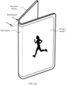
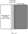
- the foldable display may be divided into three display areas: a primary display, a secondary display, and a side display.
- the foldable display changes a layout of display elements in the unfolded form and displays the display elements on the primary display in the folded form. Consequently, the display area of the display is not fully utilized.
- Document CN 107 765 971 A discloses a user interface display method and equipment, and belongs to the field of human-computer interaction. The method comprises the following steps: monitoring the working state of a folded display screen; when the working state is switched into an outward folding state from an opening state, determining a visible screen area and an off screen area in two screen areas; controlling the visible screen area to be under a display state; and controlling the off screen area to be under an off state.
- the working state of the folded display screen is the outward folding state
- the visible screen area and the off screen area in two screen areas of the folded display screen are determined
- the off screen area is controlled to be under the off screen state
- electric quantity consumption is saved
- the off screen area can prevented from being touched by a user by mistake
- the use convenience of the terminal with the folded display screen is improved.
- Document CN 107 765 968 A discloses a task switching method and device, a terminal and a computer readable storage medium, and belongs to the technical field of terminals.
- the method and the device are applied to the terminal; the terminal comprises a foldable display screen; and after the display screen is folded, two display areas and a curved surface area between the two display areas can be formed.
- the method comprises the following steps of: when at least one task is operated at the background of the terminal in a process that display screen is located in a folding state, displaying a task identifier of the at least task in the curved surface area; detecting touch operations in the curved surface area; and when a touch operation for a target task identifier is detected, switching a target task to the foreground of the target display area to be displayed, wherein the target task is any task in the at least one task, and the target display area is an area for displaying the foreground task in the two display areas.
- task identifiers of the background tasks are displayed in the curved surface area, so that task switching can be carried out through the touch operationsof the task identifiers, and then the task switching step is simplified.
- Document EP 3 159 784 A1 provides an electronic device that comprises a bended display, a sensor unit, and a processor.
- the bended display includes a front display region, a side display region, and a back display region, which respectively correspond to a front face, a side face, and a back face of the electronic device.
- the sensor unit detects a motion of the electronic device. If an event occurs while content is displayed on the front display region, the processor controls the bended display to display a graphic object corresponding to the event on the front display region, and also controls the bended display to display a first screen corresponding to the graphic object on the back display region, based on the detected motion of the electronic device.
- This application provides a display control method and a related electronic device, computer storage medium, and computer program product, to display a beautified layer with a pattern on a side display of a foldable display. This fully utilizes a display area of the foldable display, and improves visual experience of a user.
- the present invention is defined by the attached independent claims; dependent claims define preferred embodiments.
- this application provides a display control method, applied to an electronic device configured with a foldable display.
- the method includes: First, the electronic device displays a first interface in full screen by using the foldable display. Then, the electronic device receives a first folding operation for the foldable display. A display area of the foldable display is divided into a primary display, a secondary display, and a side display.
- the electronic device displays a second interface on the primary display or the secondary display of the foldable display, and displays a beautified layer on the side display of the foldable display. A pattern is displayed at the beautified layer, and interface content of the second interface is the same as interface content of the first interface.
- the method further includes: The electronic device receives a first input operation for the beautified layer on the side display. In response to the first input operation, the electronic device switches between patterns displayed at the beautified layer. In this way, the user can conveniently change the pattern at the beautified layer on the side display. This improves user experience.
- the method further includes: The electronic device receives a second input operation for the beautified layer on the side display. In response to the second input operation, the electronic device cancels displaying the beautified layer on the side display. In this way, the electronic device can receive a user input based on a user requirement, and cancel displaying the beautified layer on the side display of the foldable display. This improves user experience.
- the method further includes: The electronic device receives a third input operation for the side display. In response to the third input operation, the electronic device displays the beautified layer on the side display. In this way, after the electronic device cancels displaying the beautified layer on the side display, the electronic device can receive a user input based on a user requirement, and display the beautified layer on the side display again. This improves user experience.
- the method further includes: The electronic device receives a second unfolding operation for the foldable display.
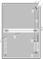
- the electronic device extends, within a second time period, the second interface to the first interface that is displayed on the foldable display in full screen, and the electronic device slides, within the first time period, the beautified layer out of the display area of the foldable display along a direction perpendicular to a direction in which the second interface is extended.
- progressive exit of the beautified layer displayed in the bent area can be implemented, and continuous change of the application interface from primary-display display to full-screen display can be implemented. This avoids bringing a skipping visual sense to the user when the application interface is extended to the full screen, and improves visual experience of the user.
- that the electronic device displays a second interface on the primary display or the secondary display of the foldable display includes: The electronic device determines whether the primary display of the foldable display faces upward relative to a horizontal plane. If the primary display of the foldable display faces upward relative to a horizontal plane, the electronic device displays the second interface on the primary display of the foldable display. If the primary display of the foldable display does not face upward relative to a horizontal plane, the electronic device displays the second interface on the secondary display of the foldable display. In this way, when the foldable display is switched from the unfolded form to the folded form, the user can view interface content output by a display system of the electronic device in the first time.
- this application provides an electronic device, including one or more memories, a foldable display, and one or more memories.
- the one or more memories are coupled to the one or more processors, and the foldable display communicates with the one or more processors.
- the one or more memories are configured to store computer program code, the computer program code includes computer instructions, and when the one or more processors execute the computer instructions, the electronic device is enabled to perform the display control method in any possible implementations of the foregoing aspect.
- an embodiment of this application provides a computer storage medium, including computer instructions.
- the computer instructions When the computer instructions are run on an electronic device, the electronic device is enabled to perform the display control method in any possible implementations of the foregoing aspect.
- an embodiment of this application provides a computer program product.
- the computer program product runs on a computer, the computer is enabled to perform the display control method in any possible implementations of the foregoing aspect.
- first and second are merely intended for description, and shall not be understood as an indication or implication of relative importance or implicit indication of a quantity of indicated technical features.
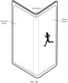
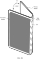
- FIG. 1 is a schematic diagram of a structure of an electronic device 100.
- the following uses the electronic device 100 as an example to specifically describe this embodiment. It should be understood that the electronic device 100 shown in FIG. 1 is merely an example, and the electronic device 100 may have more or fewer components than those shown in FIG. 1 , or may combine two or more components, or may have different component configurations. Various components shown in the figure may be implemented in hardware, software, or a combination of hardware and software that includes one or more signal processing and/or application-specific integrated circuits.
- the electronic device 100 may include a processor 110, an external memory interface 120, an internal memory 121, a universal serial bus (universal serial bus, USB) interface 130, a charging management module 140, a power management module 141, a battery 142, an antenna 1, an antenna 2, a mobile communications module 150, a wireless communications module 160, an audio module 170, a speaker 170A, a receiver 170B, a microphone 170C, a headset jack 170D, a sensor module 180, a button 190, a motor 191, an indicator 192, a camera 193, a display 194, a subscriber identification module (subscriber identification module, SIM) card interface 195, and the like.
- a processor 110 an external memory interface 120, an internal memory 121, a universal serial bus (universal serial bus, USB) interface 130, a charging management module 140, a power management module 141, a battery 142, an antenna 1, an antenna 2, a mobile communications module 150, a wireless communications module 160, an audio module 170,
- the structure shown in this embodiment of the present invention does not constitute a specific limitation on the electronic device 100.
- the electronic device 100 may include more or fewer components than those shown in the figure, combine some components, split some components, or have different component arrangements.
- the components shown in the figure may be implemented by using hardware, software, or a combination of software and hardware.
- the processor 110 may include one or more processing units.
- the processor 110 may include an application processor (application processor, AP), a modem processor, a graphics processing unit (graphics processing unit, GPU), an image signal processor (image signal processor, ISP), a controller, a memory, a video codec, a digital signal processor (digital signal processor, DSP), a baseband processor, a neural-network processing unit (Neural-network Processing Unit, NPU), and/or the like.
- Different processing units may be independent components, or may be integrated into one or more processors.
- the controller may be a nerve center and a command center of the electronic device 100.
- the controller may generate an operation control signal based on an instruction operation code and a time sequence signal, to complete control of instruction reading and instruction execution.
- a memory may be further disposed in the processor 110, and is configured to store instructions and data.
- the memory in the processor 110 is a high-speed cache memory.
- the memory may store instructions or data just used or cyclically used by the processor 110. If the processor 110 needs to use the instructions or the data again, the processor 110 may directly invoke the instructions or the data from the memory. This avoids repeated access and reduces a waiting time of the processor 110. Therefore, system efficiency is improved.
- the processor 110 may include one or more interfaces.
- the interface may include an inter-integrated circuit (inter-integrated circuit, I2C) interface, an inter-integrated circuit sound (inter-integrated circuit sound, I2S) interface, a pulse code modulation (pulse code modulation, PCM) interface, a universal asynchronous receiver/transmitter (universal asynchronous receiver/transmitter, UART) interface, a mobile industry processor interface (mobile industry processor interface, MIPI), a general-purpose input/output (general-purpose input/output, GPIO) interface, a subscriber identity module (subscriber identity module, SIM) interface, a universal serial bus (universal serial bus, USB) interface, and/or the like.
- I2C inter-integrated circuit
- I2S inter-integrated circuit sound
- PCM pulse code modulation
- PCM pulse code modulation
- UART universal asynchronous receiver/transmitter
- MIPI mobile industry processor interface
- GPIO general-purpose input/output
- the I2C interface is a two-way synchronization serial bus, and includes a serial data line (serial data line, SDA) and a serial clock line (serial clock line, SCL).
- the processor 110 may include a plurality of groups of I2C buses.
- the processor 110 may be separately coupled to the touch sensor 180K, a charger, a flash, the camera 193, and the like through different I2C bus interfaces.
- the processor 110 may be coupled to the touch sensor 180K through the I2C interface, so that the processor 110 communicates with the touch sensor 180K through the I2C bus interface, to implement a touch function of the electronic device 100.
- the I2S interface may be configured to perform audio communication.
- the processor 110 may include a plurality of groups of I2S buses.
- the processor 110 may be coupled to the audio module 170 through the I2S bus, to implement communication between the processor 110 and the audio module 170.
- the audio module 170 may transmit an audio signal to the wireless communications module 160 through the I2S interface, to implement a function of answering a call by using a Bluetooth headset.
- the PCM interface may also be configured to: perform audio communication, and sample, quantize, and code an analog signal.
- the audio module 170 may be coupled to the wireless communications module 160 through a PCM bus interface.
- the audio module 170 may alternatively transmit an audio signal to the wireless communications module 160 through the PCM interface, to implement a function of answering a call by using the Bluetooth headset. Both the I2S interface and the PCM interface may be configured to perform audio communication.
- the UART interface is a universal serial data bus, and is configured to perform asynchronous communication.
- the bus may be a two-way communications bus, and converts to-be-transmitted data between serial communication and parallel communication.
- the UART interface is usually configured to connect the processor 110 to the wireless communications module 160.
- the processor 110 communicates with a Bluetooth module in the wireless communications module 160 through the UART interface, to implement a Bluetooth function.
- the audio module 170 may transmit an audio signal to the wireless communications module 160 through the UART interface, to implement a function of playing music by using the Bluetooth headset.
- the MIPI interface may be configured to connect the processor 110 to a peripheral device such as the display 194 or the camera 193.
- the MIPI interface includes a camera serial interface (camera serial interface, CSI), a display serial interface (display serial interface, DSI), and the like.
- the processor 110 communicates with the camera 193 through the CSI interface, to implement a photographing function of the electronic device 100.
- the processor 110 communicates with the display 194 through the DSI interface, to implement a display function of the electronic device 100.
- the GPIO interface may be configured by using software.
- the GPIO interface may be configured as a control signal or a data signal.
- the GPIO interface may be configured to connect the processor 110 to the camera 193, the display 194, the wireless communications module 160, the audio module 170, the sensor module 180, and the like.
- the GPIO interface may alternatively be configured as the I2C interface, the I2S interface, the UART interface, the MIPI interface, or the like.
- an interface connection relationship between the modules that is shown in this embodiment of the present invention is merely an example for description, and does not constitute a limitation on a structure of the electronic device 100.
- the electronic device 100 may alternatively use an interface connection manner different from an interface connection manner in this embodiment, or a combination of a plurality of interface connection manners.
- the charging management module 140 is configured to receive a charging input from the charger.
- the charger may be a wireless charger or a wired charger.
- the charging management module 140 may receive a charging input from the wired charger through the USB interface 130.
- the charging management module 140 may receive a wireless charging input through a wireless charging coil of the electronic device 100.
- the charging management module 140 may further supply power to the electronic device by using the power management module 141 while charging the battery 142.
- the power management module 141 is configured to connect the battery 142 and the charging management module 140 to the processor 110.
- the power management module 141 receives an input from the battery 142 and/or the charging management module 140, and supplies power to the processor 110, the internal memory 121, an external memory, the display 194, the camera 193, the wireless communications module 160, and the like.
- the power management module 141 may be further configured to monitor parameters such as a battery capacity, a battery cycle count, and a battery health status (electric leakage or impedance).
- the power management module 141 may alternatively be disposed in the processor 110.
- the power management module 141 and the charging management module 140 may alternatively be disposed in a same device.
- a wireless communication function of the electronic device 100 may be implemented through the antenna 1, the antenna 2, the mobile communications module 150, the wireless communications module 160, the modem processor, the baseband processor, and the like.
- the antenna 1 and the antenna 2 are configured to transmit and receive electromagnetic wave signals.
- Each antenna in the electronic device 100 may be configured to cover one or more communication bands. Different antennas may further be multiplexed, to improve antenna utilization.
- the antenna 1 may be multiplexed as a diversity antenna of a wireless local area network. In some other embodiments, the antenna may be used in combination with a tuning switch.
- the modem processor may include a modulator and a demodulator.
- the modulator is configured to modulate a to-be-sent low-frequency baseband signal into a medium-high-frequency signal.
- the demodulator is configured to demodulate a received electromagnetic wave signal into a low-frequency baseband signal. Then, the demodulator transmits the low-frequency baseband signal obtained through demodulation to the baseband processor for processing. After being processed by the baseband processor, the low-frequency baseband signal is transmitted to the application processor.
- the application processor outputs a sound signal through an audio device (which is not limited to the speaker 170A, the receiver 170B, or the like), or displays an image or a video through the display 194.
- the modem processor may be an independent component. In some other embodiments, the modem processor may be independent of the processor 110, and disposed in a same device with the mobile communications module 150 or another function module.
- the wireless communications module 160 may provide a solution, applied to the electronic device 100, to wireless communication including a wireless local area network (wireless local area network, WLAN) (for example, a wireless fidelity (wireless fidelity, Wi-Fi) network), Bluetooth (Bluetooth, BT), a global navigation satellite system (global navigation satellite system, GNSS), frequency modulation (frequency modulation, FM), a near field communication (near field communication, NFC) technology, an infrared (infrared, IR) technology, or the like.
- the wireless communications module 160 may be one or more components integrating at least one communications processor module.
- the wireless communications module 160 receives an electromagnetic wave through the antenna 2, performs frequency modulation and filtering on an electromagnetic wave signal, and sends a processed signal to the processor 110.
- the wireless communications module 160 may further receive a to-be-sent signal from the processor 110, perform frequency modulation and amplification on the signal, and convert a processed signal into an electromagnetic wave for radiation through the antenna 2.
- the antenna 1 and the mobile communications module 150 are coupled, and the antenna 2 and the wireless communications module 160 are coupled, so that the electronic device 100 can communicate with a network and another device by using a wireless communications technology.
- the wireless communications technology may include a global system for mobile communications (global system for mobile communications, GSM), a general packet radio service (general packet radio service, GPRS), code division multiple access (code division multiple access, CDMA), wideband code division multiple access (wideband code division multiple access, WCDMA), time-division code division multiple access (time-division code division multiple access, TD-SCDMA), long term evolution (long term evolution, LTE), BT, a GNSS, a WLAN, NFC, FM, an IR technology, and/or the like.
- GSM global system for mobile communications
- GPRS general packet radio service
- code division multiple access code division multiple access
- CDMA wideband code division multiple access
- WCDMA wideband code division multiple access
- time-division code division multiple access time-division code
- the GNSS may include a global positioning system (global positioning system, GPS), a global navigation satellite system (global navigation satellite system, GLONASS), a BeiDou navigation satellite system (Beidou navigation satellite system, BDS), a quasi-zenith satellite system (quasi-zenith satellite system, QZSS), and/or a satellite based augmentation system (satellite based augmentation system, SBAS).
- GPS global positioning system
- GLONASS global navigation satellite system
- BeiDou navigation satellite system BeiDou navigation satellite system
- BDS BeiDou navigation satellite system
- QZSS quasi-zenith satellite system
- SBAS satellite based augmentation system
- the electronic device 100 may display, on the primary display, the interface content output by the display system.
- the electronic device 100 may display, on the secondary display, the interface content output by the display system.
- the electronic device 100 may further include an angular transducer (not shown in FIG. 1 ).
- the angular transducer may be disposed at the bending part of the foldable display.
- the electronic device 100 may measure, by using the angular transducer (not shown in FIG. 1 ) disposed at the bending part of the foldable display, an included angle between both ends of the middle bending part of the foldable display.
- the electronic device 100 may identify, by using the angular transducer, that the foldable display goes into the unfolded state.
- the electronic device 100 may identify, by using the angular transducer, that the foldable display goes into the folded form.
- the electronic device 100 may also identify, by using a physical switch disposed at the bending part of the foldable display, whether the foldable display is in the folded form. For example, when the electronic device receives a folding operation performed by a user on the foldable display, the physical switch disposed on the electronic device is triggered to be turned on, and the electronic device 100 may determine that the foldable display is in the folded form. When the electronic device 100 receives an unfolding operation performed by the user on the foldable display, the physical switch disposed on the electronic device is triggered to be turned off, and the electronic device may determine that the foldable display is in the unfolded form.
- a physical switch disposed at the bending part of the foldable display may also identify, by using a physical switch disposed at the bending part of the foldable display, whether the foldable display is in the folded form. For example, when the electronic device receives a folding operation performed by a user on the foldable display, the physical switch disposed on the electronic device is triggered to be turned on, and the electronic device 100 may determine
- the foldable display may display content in full screen.
- the interface content when the interface content is displayed in full screen, the interface content may occupy a part of the display area of the foldable display.
- the display 194 is an abnormally cut screen (Notch screen)
- the interface content is displayed in a middle part of the abnormally cut screen.
- a black screen occurs on a side edge or edges of two sides, it may also be considered that the foldable display displays the interface content in full screen.
- the ISP is configured to process data fed back by the camera 193. For example, during photographing, a shutter is pressed, light is transmitted to a photosensitive element of the camera through a lens, an optical signal is converted into an electrical signal, and the photosensitive element of the camera transmits the electrical signal to the ISP for processing, to convert the electrical signal into a visible image.
- the ISP may further perform algorithm optimization on noise, brightness, and complexion of the image.
- the ISP may further optimize parameters such as exposure and color temperature of a photographing scenario.
- the ISP may be disposed in the camera 193.
- the camera 193 is configured to capture a static image or a video. An optical image of an object is generated through the lens, and is projected onto the photosensitive element.
- the photosensitive element may be a charge coupled device (charge coupled device, CCD) or a complementary metal-oxide-semiconductor (complementary metal-oxide-semiconductor, CMOS) phototransistor.
- CCD charge coupled device
- CMOS complementary metal-oxide-semiconductor
- the photosensitive element converts an optical signal into an electrical signal, and then transmits the electrical signal to the ISP to convert the electrical signal into a digital image signal.
- the ISP outputs the digital image signal to the DSP for processing.
- the DSP converts the digital image signal into a standard image signal in an RGB format, a YUV format, or the like.
- the electronic device 100 may include one or N cameras 193, where N is a positive integer greater than 1.
- the NPU is a neural-network (neural-network, NN) computing processor, quickly processes input information by referring to a structure of a biological neural network, for example, by referring to a transfer mode between human brain neurons, and may further continuously perform self-learning.
- Applications such as intelligent cognition of the electronic device 100, such as image recognition, facial recognition, speech recognition, and text understanding, can be implemented by using the NPU.
- the external memory interface 120 may be configured to connect to an external memory card, for example, a micro SD card, to extend a storage capability of the electronic device 100.
- the external storage card communicates with the processor 110 through the external memory interface 120, to implement a data storage function. For example, files such as music and a video are stored in the external storage card.
- the internal memory 121 may be configured to store computer executable program code.
- the executable program code includes instructions.
- the processor 110 runs the instructions stored in the internal memory 121, to implement various function applications and data processing of the electronic device 100.
- the internal memory 121 may include a program storage area and a data storage area.
- the program storage area may store an operating system, an application required by at least one function (for example, a sound playing function or an image playing function), and the like.
- the data storage area may store data (for example, audio data, and a phone book) created in a process of using the electronic device 100, and the like.
- the internal memory 121 may include a high-speed random access memory, or may include a nonvolatile memory, for example, at least one magnetic disk storage component, a flash memory component, or a universal flash storage (universal flash storage, UFS).
- the audio module 170 is configured to convert digital audio information into an analog audio signal for output, and is also configured to convert an analog audio input into a digital audio signal.
- the audio module 170 may be further configured to code and decode an audio signal.
- the audio module 170 may be disposed in the processor 110, or some function modules of the audio module 170 are disposed in the processor 110.
- the speaker 170A also referred to as a "horn” is configured to convert an electrical audio signal into a sound signal.
- the electronic device 100 may be configured to listen to music or answer a hands-free call by using the speaker 170A.
- the receiver 170B also referred to as an "earpiece”, is configured to convert an electrical audio signal into a sound signal. When a call is answered or voice information is received by using the electronic device 100, the receiver 170B may be put close to a human ear to receive a voice.
- the headset interface 170D is configured to connect to a wired headset.
- the headset interface 170D may be the USB interface 130, or may be a 3.5 mm open mobile terminal platform (open mobile terminal platform, OMTP) standard interface or a cellular telecommunications industry association of the USA (cellular telecommunications industry association of the USA, CTIA) standard interface.
- the temperature sensor 180J is configured to detect a temperature.
- the electronic device 100 executes a temperature processing policy based on the temperature detected by the temperature sensor 180J. For example, when the temperature reported by the temperature sensor 180J exceeds a threshold, the electronic device 100 lowers performance of a processor located near the temperature sensor 180J, to reduce power consumption to implement thermal protection.
- the electronic device 100 heats the battery 142 to prevent the electronic device 100 from being abnormally powered off because of a low temperature.
- the electronic device 100 boosts an output voltage of the battery 142, to prevent abnormal power-off caused by a low temperature.
- the button 190 includes a power button, a volume button, and the like.
- the button 190 may be a mechanical button, or may be a touch button.
- the electronic device 100 may receive a key input, and generate a key signal input related to a user setting and function control of the electronic device 100.
- the electronic device may receive an input operation 312 (for example, tapping) of the user on the Gallery application icon 311, and in response to the input operation, a mobile terminal may display a gallery application interface 410 shown in FIG. 4 .
- an input operation 312 for example, tapping
- a mobile terminal may display a gallery application interface 410 shown in FIG. 4 .
- the electronic device may display, in a reduced scale, content displayed when the foldable display is in the unfolded form, on a display area easily seen by the user (for example, a display area facing upwards relative to the horizontal plane). In this way, it can be convenient for the user to see interface content displayed on the foldable display in time when a form of the foldable display is switched.
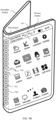
- the foldable display of the electronic device is in the unfolded form.
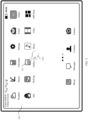
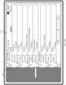
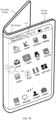
- the electronic device may display a home screen 810 in full screen.
- the home screen 810 displays a page on which application icons are placed.
- the page includes a plurality of application icons (for example, a Weather application icon, a Stocks application icon, a Calculator application icon, a Settings application icon 811, an Email application icon, an Alipay application icon, a Facebook application icon, a Browser application icon, a Gallery application icon, a Music application icon, a Video application icon, and an App Store application icon).
- the electronic device may receive an input operation 812 (for example, tapping) of the user on the Settings application icon 811, and in response to the input operation 812, the electronic device may display a settings application interface 820 shown in FIG. 8B by using the foldable display.
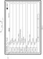
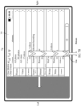
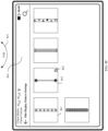
- the side display pattern setting window 850 may include a pattern 851, a cancel button 852, a blurring setting bar 853, a transparency setting bar 854, and a confirm button 855.
- the cancel button 852 is used to receive an input of the user.
- the electronic device may not save a blurring degree value displayed in the blurring setting bar 853 and a transparency value displayed in the transparency setting bar 854, and returns to the side display pattern setting interface 840 shown in FIG. 8D .
- the blurring setting bar 853 may be used to receive an input of the user, to adjust a blurring degree of the pattern 851.
- the transparency setting bar 854 may be used to receive an input of the user, to adjust transparency of the pattern 851.
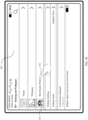
- the electronic device may receive a folding operation 864 of the user.
- the electronic device may switch the foldable display from the unfolded form to the folded form.
- the electronic device may display, on the side display, a beautified layer 880 shown in FIG. 8G .
- the electronic device may display, on the primary display or the secondary display of the foldable display, interface content output by the system, and display the beautified layer on the side display. A pattern is displayed at the beautified layer.
- the electronic device may receive an input operation of the user for the side display. In response to the input operation, the electronic device may not display the beautified layer on the side display. In this way, the electronic device can receive a user input based on a user requirement, and cancel displaying the beautified layer on the side display of the foldable display. This improves user experience.
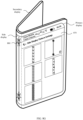
- the foldable display is in the folded form, and the electronic device displays the home screen 910 on the primary display of the foldable display, and displays the beautified layer 920 on the side display of the foldable display.
- the pattern 923 is displayed at the beautified layer 920.
- the electronic device when the foldable display is in the folded form, if the electronic device currently opens a photographing application or a video playback application, the electronic device may display application interface content by using both the primary display and the secondary display. For example, the electronic device may display a photographing interface on both the primary display and the secondary display, or the electronic device may display a video playback interface on both the primary display and the secondary display.
- the electronic device displays an application interface by using both the primary display and the secondary display of the foldable display, and displays a beautified layer by using a side display.
- the electronic device When the electronic device opens the video playback application to play a video, to enable both a user and another user sitting opposite to the user to watch the video, the electronic device may simultaneously display video playback content by using the primary display and the secondary display of the foldable display, and display the beautified layer by using the side display.
- the example is merely used to explain this application and shall not constitute a limitation.
- the electronic device when the foldable display is in the unfolded state, the electronic device may display an interface (for example, a home screen or the application interface) on the foldable display in full screen.
- the electronic device may display, by scaling down the interface on the primary display or the secondary display, the interface that is displayed in full screen when the foldable display is in the unfolded state, or display, on both the primary display and the secondary display, interface content whose interface is scaled down.
- the electronic device displays the beautified layer on the side display of the foldable display, and the beautified layer may display the pattern (for example, a spine pattern). Because the beautified layer with the pattern (for example, a spine-type pattern) is displayed on the side display, visual experience of a user is increased.
- FIG. 12 is a schematic flowchart of a display control method according to an embodiment of this application. As shown in FIG. 12 , the method includes the following steps.
- An electronic device may display a first interface in full screen by using a foldable display.
- the electronic device may receive a first folding operation for the foldable display.
- the electronic device in response to the unfolding operation 511, within the second time period (for example, within 0.5s), the electronic device may slide the beautified layer displayed on the side display out along the bottom direction or the top direction of the bent area. At the same time, the electronic device may extend the application interface displayed on the primary display along the secondary display direction until the application interface is displayed on the foldable display in full screen.
- the electronic device may slide the beautified layer displayed on the side display out along the bottom direction or the top direction of the bent area.
- the electronic device may extend the application interface displayed on the primary display along the secondary display direction until the application interface is displayed on the foldable display in full screen.
- FIG. 7A , FIG. 7B , and FIG. 7C Details are not described herein again.
- progressive exit of the beautified layer displayed in the bent area can be implemented, and continuous change of the application interface from primary-display display to full-screen display can be implemented. This avoids bringing a skipping visual sense to the user when the application interface is extended to the full screen, and
- the electronic device may determine whether the primary display of the foldable display faces upward relative to a horizontal plane, and if yes, the electronic device displays the second interface on the primary display of the foldable display, or if no, the electronic device displays the second interface on the secondary display of the foldable display.
- the electronic device 100 may display, on the primary display, interface content output by a display system.
- the electronic device 100 may display, on the secondary display, the interface content output by the display system. In this way, when the foldable display is switched from the unfolded form to the folded form, the user can view interface content output by a display system of the electronic device in the first time.
Landscapes
- Engineering & Computer Science (AREA)
- Theoretical Computer Science (AREA)
- General Engineering & Computer Science (AREA)
- Physics & Mathematics (AREA)
- General Physics & Mathematics (AREA)
- Human Computer Interaction (AREA)
- Computer Hardware Design (AREA)
- Signal Processing (AREA)
- Software Systems (AREA)
- Computer Networks & Wireless Communication (AREA)
- Environmental & Geological Engineering (AREA)
- Multimedia (AREA)
- Mathematical Physics (AREA)
- Computing Systems (AREA)
- User Interface Of Digital Computer (AREA)
- Digital Computer Display Output (AREA)
Claims (10)
- Anzeigesteuerungsverfahren, angewendet auf eine elektronische Vorrichtung (100), die mit einer faltbaren Anzeige konfiguriert ist, wobei das Verfahren Folgendes umfasst:Anzeigen (S1201) einer ersten Schnittstelle (630, 730) im Vollbild durch die elektronische Vorrichtung (100) unter Verwendung der faltbaren Anzeige;Empfangen (S1202) eines ersten Faltvorgangs für die faltbare Anzeige durch die elektronische Vorrichtung (100), wobei ein Anzeigebereich der faltbaren Anzeige in eine Primäranzeige, eine Sekundäranzeige und eine Seitenanzeige unterteilt ist; undals Reaktion auf den ersten Faltvorgang, Anzeigen (S1203) einer zweiten Schnittstelle (610, 710) auf der Primäranzeige oder der Sekundäranzeige der faltbaren Anzeige durch die elektronische Vorrichtung (100) und Anzeigen einer verschönerten Schicht (620, 720) auf der Seitenanzeige der faltbaren Anzeige, wobei ein Muster auf der verschönerten Schicht (620, 720) angezeigt wird und ein Schnittstelleninhalt der zweiten Schnittstelle (610, 710) gleich einem Schnittstelleninhalt der ersten Schnittstelle (630, 730) ist,wobei das Verfahren ferner Folgendes umfasst:Empfangen eines zweiten Entfaltvorgangs für die faltbare Anzeige durch die elektronische Vorrichtung (100); und, als Reaktion auf den zweiten Entfaltvorgang, Erweitern der zweiten Schnittstelle (710) auf die erste Schnittstelle (730), die auf der faltbaren Anzeige im Vollbild angezeigt wird, durch die elektronische Vorrichtung (100) innerhalb eines zweiten Zeitraums und Verschieben der verschönerten Schicht (720) aus dem Anzeigebereich der faltbaren Anzeige entlang einer Richtung senkrecht zu einer Richtung, in der die zweite Schnittstelle (710) verlängert ist, durch die elektronische Vorrichtung (100) innerhalb eines ersten Zeitraums,wobei als Reaktion auf den zweiten Entfaltvorgang ein stufenweises Verschwinden der in dem gebogenen Bereich angezeigten verschönerten Schicht umgesetzt wird und außerdem ein kontinuierliches Wechseln der zweiten Schnittstelle (710) von der Primäranzeige zur Vollbildanzeige umgesetzt wird,sodass die verschönerte Schicht (720) der Seitenanzeige in einer Richtung von oben nach unten der Seitenanzeige gleitet und sich die zweite Schnittstelle (710) ebenfalls synchron entlang der Richtung erstreckt, in der sich die Sekundäranzeige befindet.
- Verfahren nach Anspruch 1, wobei das Verfahren ferner Folgendes umfasst:Empfangen eines ersten Eingabevorgangs für die verschönerte Schicht (620, 720) auf der Seitenanzeige durch die elektronische Vorrichtung (100); undals Reaktion auf den ersten Eingabevorgang, Umschalten zwischen Mustern, die auf der verschönerten Schicht (620, 720) angezeigt werden, durch die elektronische Vorrichtung (100).
- Verfahren nach Anspruch 1, wobei das Verfahren ferner Folgendes umfasst:Empfangen eines zweiten Eingabevorgangs für die verschönerte Schicht (620, 720) auf der Seitenanzeige durch die elektronische Vorrichtung (100); undals Reaktion auf den zweiten Eingabevorgang, Abbrechen der Anzeige der verschönerten Schicht (620, 720) auf der Seitenanzeige durch die elektronische Vorrichtung (100).
- Verfahren nach Anspruch 3, wobei nach dem Abbrechen der Anzeige der verschönerten Schicht (620, 720) auf der Seitenanzeige durch die elektronische Vorrichtung (100) das Verfahren ferner Folgendes umfasst:Empfangen eines dritten Eingabevorgangs für die Seitenanzeige durch die elektronische Vorrichtung (100); undals Reaktion auf den dritten Eingabevorgang, Anzeigen der verschönerten Schicht (620, 720) auf der Seitenanzeige durch die elektronische Vorrichtung (100).
- Verfahren nach einem der Ansprüche 1 bis 4, wobei der erste Zeitraum 0,5 Sek. beträgt.
- Verfahren nach einem der Ansprüche 1 bis 5, wobei der zweite Zeitraum 0,5 Sek. beträgt.
- Verfahren nach Anspruch 1, wobei das Anzeigen der zweiten Schnittstelle (610, 710) durch die elektronische Vorrichtung (100) auf der Primäranzeige oder der Sekundäranzeige der faltbaren Anzeige Folgendes umfasst:
Bestimmen, durch die elektronische Vorrichtung (100), ob die Primäranzeige der faltbaren Anzeige relativ zu einer horizontalen Ebene nach oben weist, und, wenn die Primäranzeige der faltbaren Anzeige relativ zu einer horizontalen Ebene nach oben weist, Anzeigen der zweiten Schnittstelle (610, 710) auf der Primäranzeige der faltbaren Anzeige durch die elektronische Vorrichtung (100), oder, wenn die Primäranzeige der faltbaren Anzeige relativ zu einer horizontalen Ebene nicht nach oben weist, Anzeigen der zweiten Schnittstelle (610, 710) auf der Sekundäranzeige der faltbaren Anzeige durch die elektronische Vorrichtung (100). - Elektronische Vorrichtung (100), die einen oder mehrere Speicher, eine faltbare Anzeige und einen oder mehrere Prozessoren (110) umfasst, wobei der eine oder die mehreren Speicher mit dem einen oder den mehreren Prozessoren (100) gekoppelt sind, die faltbare Anzeige mit dem einen oder den mehreren Prozessoren (100) kommuniziert und der eine oder die mehreren Speicher dazu konfiguriert sind, Computerprogrammcode zu speichern, wobei der Programmcode Computeranweisungen umfasst, und, wenn der eine oder die mehreren Prozessoren (100) die Computeranweisungen ausführen, die elektronische Vorrichtung (100) dazu veranlasst wird, das Anzeigesteuerungsverfahren nach einem der Ansprüche 1 bis 7 durchzuführen.
- Computerspeichermedium, umfassend Anweisungen, die bei Ausführung durch einen Computer bewirken, dass der Computer das Anzeigesteuerungsverfahren nach einem der Ansprüche 1 bis 7 durchführt.
- Computerprogrammprodukt, umfassend Anweisungen, die bei Ausführung durch einen Computer bewirken, dass der Computer das Anzeigesteuerungsverfahren nach einem der Ansprüche 1 bis 7 durchführt.
Applications Claiming Priority (2)
| Application Number | Priority Date | Filing Date | Title |
|---|---|---|---|
| CN201910304644.2A CN110119295B (zh) | 2019-04-16 | 2019-04-16 | 一种显示控制方法及相关装置 |
| PCT/CN2020/076582 WO2020211532A1 (zh) | 2019-04-16 | 2020-02-25 | 一种显示控制方法及相关装置 |
Publications (3)
| Publication Number | Publication Date |
|---|---|
| EP3933577A1 EP3933577A1 (de) | 2022-01-05 |
| EP3933577A4 EP3933577A4 (de) | 2022-04-20 |
| EP3933577B1 true EP3933577B1 (de) | 2025-04-09 |
Family
ID=67521136
Family Applications (1)
| Application Number | Title | Priority Date | Filing Date |
|---|---|---|---|
| EP20790576.1A Active EP3933577B1 (de) | 2019-04-16 | 2020-02-25 | Anzeigesteuerungsverfahren und zugehörige vorrichtung |
Country Status (5)
| Country | Link |
|---|---|
| US (1) | US20220222027A1 (de) |
| EP (1) | EP3933577B1 (de) |
| JP (1) | JP7196335B2 (de) |
| CN (1) | CN110119295B (de) |
| WO (1) | WO2020211532A1 (de) |
Families Citing this family (29)
| Publication number | Priority date | Publication date | Assignee | Title |
|---|---|---|---|---|
| CN110119295B (zh) * | 2019-04-16 | 2022-05-17 | 华为技术有限公司 | 一种显示控制方法及相关装置 |
| KR102782431B1 (ko) * | 2019-05-15 | 2025-03-18 | 삼성전자 주식회사 | 전자 장치 및 그의 알림 제공 방법 |
| CN114679537B (zh) * | 2019-05-22 | 2023-04-28 | 华为技术有限公司 | 一种拍摄方法及终端 |
| CN110532051B (zh) * | 2019-08-16 | 2021-06-04 | 珠海格力电器股份有限公司 | 显示快捷操作栏的方法、装置、折叠屏设备及存储介质 |
| CN114006625B (zh) * | 2019-08-26 | 2023-03-28 | 华为技术有限公司 | 一种分屏显示方法与电子设备 |
| CN112445448B (zh) * | 2019-08-30 | 2022-07-22 | 华为技术有限公司 | 一种柔性屏显示方法和电子设备 |
| CN112558898A (zh) * | 2019-09-10 | 2021-03-26 | 华为技术有限公司 | 显示方法及电子设备 |
| CN112527229B (zh) * | 2019-09-17 | 2023-03-10 | 华为技术有限公司 | 一种屏幕侧面区域显示方法及电子设备 |
| CN110531864B (zh) * | 2019-09-18 | 2026-02-10 | 华为技术有限公司 | 一种手势交互方法、装置及终端设备 |
| CN112615947B (zh) * | 2019-09-18 | 2022-03-25 | 华为技术有限公司 | 快速进入应用的方法与折叠屏电子设备 |
| CN110825301A (zh) * | 2019-09-25 | 2020-02-21 | 华为技术有限公司 | 一种界面切换方法及电子设备 |
| CN112583957A (zh) * | 2019-09-30 | 2021-03-30 | 华为技术有限公司 | 电子设备的显示方法、电子设备与计算机可读存储介质 |
| CN110825474B (zh) * | 2019-10-31 | 2023-03-31 | 维沃移动通信有限公司 | 界面显示方法、装置和电子设备 |
| CN110928619B (zh) * | 2019-10-31 | 2023-10-20 | 维沃移动通信有限公司 | 壁纸设置方法、装置、电子设备及介质 |
| CN112825232B (zh) * | 2019-11-20 | 2023-01-06 | 华为技术有限公司 | 一种补偿方法及电子设备 |
| JP7447494B2 (ja) * | 2020-01-08 | 2024-03-12 | 富士フイルムビジネスイノベーション株式会社 | 表示装置及び表示制御プログラム |
| CN113098152B (zh) * | 2020-01-08 | 2025-07-25 | 北京小米移动软件有限公司 | 无线充电方法及装置、折叠屏电子设备、存储介质 |
| CN111416893B (zh) * | 2020-03-13 | 2021-03-16 | 西安闻泰电子科技有限公司 | 可折叠屏幕和终端设备 |
| CN111596726A (zh) * | 2020-05-20 | 2020-08-28 | 上海闻泰信息技术有限公司 | 折叠显示屏、折叠屏显示模式切换方法、装置和存储介质 |
| KR102911825B1 (ko) * | 2020-08-04 | 2026-01-14 | 삼성전자주식회사 | 전자 장치 및 그의 화면을 제어하는 방법 |
| CN114442972B (zh) * | 2020-10-31 | 2024-09-24 | 华为技术有限公司 | 一种投屏方法及电子设备 |
| CN114584752B (zh) * | 2020-11-30 | 2024-02-02 | 华为技术有限公司 | 图像颜色还原方法及相关设备 |
| CN114610252A (zh) * | 2020-12-08 | 2022-06-10 | 深圳市柔宇科技股份有限公司 | 可弯折的电子设备及其充电控制方法 |
| CN115113834B (zh) * | 2021-03-22 | 2024-11-26 | Oppo广东移动通信有限公司 | 一种显示方法、电子设备及存储介质 |
| CN114489535B (zh) * | 2021-08-20 | 2023-04-14 | 荣耀终端有限公司 | 外屏显示方法及电子设备 |
| CN114489882B (zh) * | 2021-12-16 | 2023-05-19 | 成都鲁易科技有限公司 | 浏览器动态皮肤的实现方法及装置、存储介质 |
| CN114895748B (zh) * | 2022-04-29 | 2025-03-18 | 西安中诺通讯有限公司 | 折叠屏终端及其解锁方法、装置及计算机可读存储介质 |
| CN119645275B (zh) * | 2023-09-11 | 2026-04-10 | 荣耀终端股份有限公司 | 显示壁纸的方法及相关装置 |
| CN120780391A (zh) * | 2024-04-09 | 2025-10-14 | 北京小米移动软件有限公司 | 显示方法、装置、电子设备及存储介质 |
Family Cites Families (30)
| Publication number | Priority date | Publication date | Assignee | Title |
|---|---|---|---|---|
| US20140375530A1 (en) * | 2010-08-10 | 2014-12-25 | Stephen E. Delaporte | Reconfigurable touch screen computing device |
| US10234902B2 (en) * | 2010-08-10 | 2019-03-19 | Lepton Computing Llc | Reconfigurable touch screen computing device |
| KR101916416B1 (ko) * | 2012-07-30 | 2018-11-08 | 삼성전자주식회사 | 플렉서블 디스플레이 장치 및 그 디스플레이 방법 |
| JP6269039B2 (ja) * | 2013-12-24 | 2018-01-31 | 凸版印刷株式会社 | 可変画像表示体及び可変画像表示体の製造方法 |
| CN104267790A (zh) * | 2014-10-21 | 2015-01-07 | 王青国 | 一种双屏多用途笔记本电脑 |
| KR102358750B1 (ko) * | 2014-12-29 | 2022-02-07 | 엘지전자 주식회사 | 포터블 디바이스 및 그 제어 방법 |
| KR101942950B1 (ko) * | 2015-03-31 | 2019-01-28 | 삼성전자주식회사 | 폴더블 디바이스 및 그 제어 방법 |
| CN104965355B (zh) * | 2015-06-27 | 2019-04-26 | 武汉华星光电技术有限公司 | 一种触控显示模组及移动终端 |
| KR102423447B1 (ko) * | 2015-10-22 | 2022-07-21 | 삼성전자 주식회사 | 벤디드 디스플레이를 구비한 전자 장치 및 그 제어 방법 |
| KR102516590B1 (ko) * | 2016-01-29 | 2023-04-03 | 삼성전자주식회사 | 전자 장치 및 전자 장치에서 디스플레이의 변형에 따라 기능을 실행하기 위한 방법 |
| WO2018018442A1 (zh) | 2016-07-27 | 2018-02-01 | 深圳市柔宇科技有限公司 | 防止误操作的显示界面控制方法、装置及终端 |
| CN107665082B (zh) * | 2016-07-28 | 2020-06-02 | 中兴通讯股份有限公司 | 解锁方法及装置 |
| US10346117B2 (en) * | 2016-11-09 | 2019-07-09 | Microsoft Technology Licensing, Llc | Device having a screen region on a hinge coupled between other screen regions |
| KR102468134B1 (ko) * | 2017-06-27 | 2022-11-18 | 엘지전자 주식회사 | 전자장치 |
| WO2019000438A1 (zh) * | 2017-06-30 | 2019-01-03 | 华为技术有限公司 | 显示图形用户界面的方法及电子设备 |
| CN107580039B (zh) * | 2017-08-29 | 2020-04-14 | Oppo广东移动通信有限公司 | 传输进度的显示方法、装置及终端 |
| CN107765968A (zh) * | 2017-10-19 | 2018-03-06 | 广东欧珀移动通信有限公司 | 任务切换方法、装置、终端及计算机可读存储介质 |
| CN107765971A (zh) * | 2017-10-24 | 2018-03-06 | 广东欧珀移动通信有限公司 | 用户界面显示方法及设备 |
| CN108196810A (zh) | 2017-12-21 | 2018-06-22 | 努比亚技术有限公司 | 一种分屏显示方法、终端及计算机可读存储介质 |
| CN108228299B (zh) * | 2018-01-02 | 2021-07-16 | 联想(北京)有限公司 | 显示方法及电子设备 |
| CN108345422A (zh) * | 2018-01-15 | 2018-07-31 | 广东欧珀移动通信有限公司 | 应用控制方法、装置、移动终端及计算机可读介质 |
| CN108307068A (zh) * | 2018-01-25 | 2018-07-20 | 北京珠穆朗玛移动通信有限公司 | 副屏显示界面切换方法、移动终端及存储介质 |
| CN108229952A (zh) * | 2018-01-30 | 2018-06-29 | 努比亚技术有限公司 | 一种终端的支付方法、终端及存储介质 |
| CN109271081B (zh) * | 2018-07-28 | 2019-09-20 | 华为技术有限公司 | 滚动截屏的方法及电子设备 |
| CN108765686A (zh) * | 2018-09-05 | 2018-11-06 | 广东粤铁天福科技有限公司 | 便携式多屏展示彩票终端 |
| CN109144454A (zh) * | 2018-09-20 | 2019-01-04 | Oppo(重庆)智能科技有限公司 | 双面屏显示控制方法及相关产品 |
| CN109508070A (zh) * | 2018-09-29 | 2019-03-22 | 努比亚技术有限公司 | 显示控制方法、可弯折终端及计算机可读存储介质 |
| CN109613958A (zh) * | 2018-11-26 | 2019-04-12 | 维沃移动通信有限公司 | 一种终端设备控制方法及终端设备 |
| CN109618033A (zh) * | 2018-12-29 | 2019-04-12 | 河海大学 | 一种折叠全面屏手机 |
| CN110119295B (zh) * | 2019-04-16 | 2022-05-17 | 华为技术有限公司 | 一种显示控制方法及相关装置 |
-
2019
- 2019-04-16 CN CN201910304644.2A patent/CN110119295B/zh active Active
-
2020
- 2020-02-25 WO PCT/CN2020/076582 patent/WO2020211532A1/zh not_active Ceased
- 2020-02-25 EP EP20790576.1A patent/EP3933577B1/de active Active
- 2020-02-25 JP JP2021561751A patent/JP7196335B2/ja active Active
- 2020-02-25 US US17/604,122 patent/US20220222027A1/en not_active Abandoned
Also Published As
| Publication number | Publication date |
|---|---|
| JP2022529034A (ja) | 2022-06-16 |
| EP3933577A4 (de) | 2022-04-20 |
| CN110119295B (zh) | 2022-05-17 |
| US20220222027A1 (en) | 2022-07-14 |
| JP7196335B2 (ja) | 2022-12-26 |
| WO2020211532A1 (zh) | 2020-10-22 |
| CN110119295A (zh) | 2019-08-13 |
| EP3933577A1 (de) | 2022-01-05 |
Similar Documents
| Publication | Publication Date | Title |
|---|---|---|
| EP3933577B1 (de) | Anzeigesteuerungsverfahren und zugehörige vorrichtung | |
| EP4084450B1 (de) | Anzeigeverfahren für einen faltbaren schirm und zugehörige vorrichtung | |
| US12333202B2 (en) | Foldable screen display method and electronic device | |
| EP4057136B1 (de) | Verfahren zur anzeige eines faltschirms und zugehörige vorrichtung | |
| US20250036167A1 (en) | Video Call Display Method Applied to Electronic Device and Related Apparatus | |
| CN109889630B (zh) | 显示方法及相关装置 | |
| EP4027628B1 (de) | Steuerverfahren für ein elektronisches gerät und elektronisches gerät | |
| CN110536004B (zh) | 多传感器应用于具有柔性屏幕的电子设备的方法及电子设备 | |
| EP4020953A1 (de) | Elektronische vorrichtung mit faltbarem bildschirm und anzeigeverfahren | |
| EP3944083A1 (de) | Verfahren und vorrichtung zur kartenbezogenen verarbeitung | |
| CN110798568A (zh) | 具有折叠屏的电子设备的显示控制方法及电子设备 | |
| EP4145809A1 (de) | Anzeigesteuerungsverfahren, elektronische vorrichtung und computerlesbares speichermedium | |
| EP3879401A1 (de) | Verfahren zu automatischen bildschirmteilung, grafische benutzeroberfläche und elektronische vorrichtung | |
| EP4024189A1 (de) | Steuerungsverfahren für elektronische vorrichtung sowie elektronische vorrichtung | |
| CN111492678B (zh) | 一种文件传输方法及电子设备 | |
| US20240338163A1 (en) | Multi-screen unlocking method and electronic device | |
| EP4394636A1 (de) | Anwendungsanzeigeverfahren, elektronische vorrichtung und speichermedium | |
| CN116069156A (zh) | 拍摄参数调节方法、电子设备及存储介质 | |
| CN116540908A (zh) | 一种应用布局控制方法及相关装置 | |
| HK40068138A (en) | Index display method, electronic device and computer readable storage medium | |
| CN116127540A (zh) | 屏幕共享方法、电子设备及存储介质 | |
| HK40025100B (en) | File transmission method and electronic device | |
| HK40025100A (en) | File transmission method and electronic device |
Legal Events
| Date | Code | Title | Description |
|---|---|---|---|
| STAA | Information on the status of an ep patent application or granted ep patent |
Free format text: STATUS: THE INTERNATIONAL PUBLICATION HAS BEEN MADE |
|
| PUAI | Public reference made under article 153(3) epc to a published international application that has entered the european phase |
Free format text: ORIGINAL CODE: 0009012 |
|
| STAA | Information on the status of an ep patent application or granted ep patent |
Free format text: STATUS: REQUEST FOR EXAMINATION WAS MADE |
|
| 17P | Request for examination filed |
Effective date: 20210930 |
|
| AK | Designated contracting states |
Kind code of ref document: A1 Designated state(s): AL AT BE BG CH CY CZ DE DK EE ES FI FR GB GR HR HU IE IS IT LI LT LU LV MC MK MT NL NO PL PT RO RS SE SI SK SM TR |
|
| A4 | Supplementary search report drawn up and despatched |
Effective date: 20220321 |
|
| RIC1 | Information provided on ipc code assigned before grant |
Ipc: G06F 3/04886 20220101ALI20220315BHEP Ipc: H04M 1/02 20060101ALI20220315BHEP Ipc: G06F 3/04847 20220101ALI20220315BHEP Ipc: G06F 3/04842 20220101ALI20220315BHEP Ipc: G06F 3/0482 20130101ALI20220315BHEP Ipc: G06F 1/3287 20190101ALI20220315BHEP Ipc: G06F 1/3234 20190101ALI20220315BHEP Ipc: G06F 3/04883 20220101ALI20220315BHEP Ipc: G06F 1/3215 20190101ALI20220315BHEP Ipc: G06F 1/16 20060101ALI20220315BHEP Ipc: G06F 9/451 20180101AFI20220315BHEP |
|
| DAV | Request for validation of the european patent (deleted) | ||
| DAX | Request for extension of the european patent (deleted) | ||
| STAA | Information on the status of an ep patent application or granted ep patent |
Free format text: STATUS: EXAMINATION IS IN PROGRESS |
|
| 17Q | First examination report despatched |
Effective date: 20231208 |
|
| GRAP | Despatch of communication of intention to grant a patent |
Free format text: ORIGINAL CODE: EPIDOSNIGR1 |
|
| STAA | Information on the status of an ep patent application or granted ep patent |
Free format text: STATUS: GRANT OF PATENT IS INTENDED |
|
| INTG | Intention to grant announced |
Effective date: 20241114 |
|
| GRAS | Grant fee paid |
Free format text: ORIGINAL CODE: EPIDOSNIGR3 |
|
| GRAA | (expected) grant |
Free format text: ORIGINAL CODE: 0009210 |
|
| STAA | Information on the status of an ep patent application or granted ep patent |
Free format text: STATUS: THE PATENT HAS BEEN GRANTED |
|
| AK | Designated contracting states |
Kind code of ref document: B1 Designated state(s): AL AT BE BG CH CY CZ DE DK EE ES FI FR GB GR HR HU IE IS IT LI LT LU LV MC MK MT NL NO PL PT RO RS SE SI SK SM TR |
|
| REG | Reference to a national code |
Ref country code: GB Ref legal event code: FG4D |
|
| REG | Reference to a national code |
Ref country code: CH Ref legal event code: EP |
|
| REG | Reference to a national code |
Ref country code: DE Ref legal event code: R096 Ref document number: 602020049179 Country of ref document: DE |
|
| REG | Reference to a national code |
Ref country code: IE Ref legal event code: FG4D |
|
| REG | Reference to a national code |
Ref country code: NL Ref legal event code: MP Effective date: 20250409 |
|
| PG25 | Lapsed in a contracting state [announced via postgrant information from national office to epo] |
Ref country code: NL Free format text: LAPSE BECAUSE OF FAILURE TO SUBMIT A TRANSLATION OF THE DESCRIPTION OR TO PAY THE FEE WITHIN THE PRESCRIBED TIME-LIMIT Effective date: 20250409 |
|
| REG | Reference to a national code |
Ref country code: AT Ref legal event code: MK05 Ref document number: 1784141 Country of ref document: AT Kind code of ref document: T Effective date: 20250409 |
|
| PG25 | Lapsed in a contracting state [announced via postgrant information from national office to epo] |
Ref country code: ES Free format text: LAPSE BECAUSE OF FAILURE TO SUBMIT A TRANSLATION OF THE DESCRIPTION OR TO PAY THE FEE WITHIN THE PRESCRIBED TIME-LIMIT Effective date: 20250409 Ref country code: PT Free format text: LAPSE BECAUSE OF FAILURE TO SUBMIT A TRANSLATION OF THE DESCRIPTION OR TO PAY THE FEE WITHIN THE PRESCRIBED TIME-LIMIT Effective date: 20250811 Ref country code: FI Free format text: LAPSE BECAUSE OF FAILURE TO SUBMIT A TRANSLATION OF THE DESCRIPTION OR TO PAY THE FEE WITHIN THE PRESCRIBED TIME-LIMIT Effective date: 20250409 |
|
| REG | Reference to a national code |
Ref country code: LT Ref legal event code: MG9D |
|
| PG25 | Lapsed in a contracting state [announced via postgrant information from national office to epo] |
Ref country code: NO Free format text: LAPSE BECAUSE OF FAILURE TO SUBMIT A TRANSLATION OF THE DESCRIPTION OR TO PAY THE FEE WITHIN THE PRESCRIBED TIME-LIMIT Effective date: 20250709 Ref country code: GR Free format text: LAPSE BECAUSE OF FAILURE TO SUBMIT A TRANSLATION OF THE DESCRIPTION OR TO PAY THE FEE WITHIN THE PRESCRIBED TIME-LIMIT Effective date: 20250710 |
|
| PG25 | Lapsed in a contracting state [announced via postgrant information from national office to epo] |
Ref country code: PL Free format text: LAPSE BECAUSE OF FAILURE TO SUBMIT A TRANSLATION OF THE DESCRIPTION OR TO PAY THE FEE WITHIN THE PRESCRIBED TIME-LIMIT Effective date: 20250409 |
|
| PG25 | Lapsed in a contracting state [announced via postgrant information from national office to epo] |
Ref country code: BG Free format text: LAPSE BECAUSE OF FAILURE TO SUBMIT A TRANSLATION OF THE DESCRIPTION OR TO PAY THE FEE WITHIN THE PRESCRIBED TIME-LIMIT Effective date: 20250409 |
|
| PG25 | Lapsed in a contracting state [announced via postgrant information from national office to epo] |
Ref country code: HR Free format text: LAPSE BECAUSE OF FAILURE TO SUBMIT A TRANSLATION OF THE DESCRIPTION OR TO PAY THE FEE WITHIN THE PRESCRIBED TIME-LIMIT Effective date: 20250409 |
|
| PG25 | Lapsed in a contracting state [announced via postgrant information from national office to epo] |
Ref country code: AT Free format text: LAPSE BECAUSE OF FAILURE TO SUBMIT A TRANSLATION OF THE DESCRIPTION OR TO PAY THE FEE WITHIN THE PRESCRIBED TIME-LIMIT Effective date: 20250409 |
|
| PG25 | Lapsed in a contracting state [announced via postgrant information from national office to epo] |
Ref country code: RS Free format text: LAPSE BECAUSE OF FAILURE TO SUBMIT A TRANSLATION OF THE DESCRIPTION OR TO PAY THE FEE WITHIN THE PRESCRIBED TIME-LIMIT Effective date: 20250709 |
|
| PG25 | Lapsed in a contracting state [announced via postgrant information from national office to epo] |
Ref country code: IS Free format text: LAPSE BECAUSE OF FAILURE TO SUBMIT A TRANSLATION OF THE DESCRIPTION OR TO PAY THE FEE WITHIN THE PRESCRIBED TIME-LIMIT Effective date: 20250809 |
|
| PG25 | Lapsed in a contracting state [announced via postgrant information from national office to epo] |
Ref country code: LV Free format text: LAPSE BECAUSE OF FAILURE TO SUBMIT A TRANSLATION OF THE DESCRIPTION OR TO PAY THE FEE WITHIN THE PRESCRIBED TIME-LIMIT Effective date: 20250409 |
|
| REG | Reference to a national code |
Ref country code: DE Ref legal event code: R097 Ref document number: 602020049179 Country of ref document: DE |
|
| PG25 | Lapsed in a contracting state [announced via postgrant information from national office to epo] |
Ref country code: SM Free format text: LAPSE BECAUSE OF FAILURE TO SUBMIT A TRANSLATION OF THE DESCRIPTION OR TO PAY THE FEE WITHIN THE PRESCRIBED TIME-LIMIT Effective date: 20250409 Ref country code: DK Free format text: LAPSE BECAUSE OF FAILURE TO SUBMIT A TRANSLATION OF THE DESCRIPTION OR TO PAY THE FEE WITHIN THE PRESCRIBED TIME-LIMIT Effective date: 20250409 |
|
| PGFP | Annual fee paid to national office [announced via postgrant information from national office to epo] |
Ref country code: FR Payment date: 20251231 Year of fee payment: 7 |
|
| PG25 | Lapsed in a contracting state [announced via postgrant information from national office to epo] |
Ref country code: CZ Free format text: LAPSE BECAUSE OF FAILURE TO SUBMIT A TRANSLATION OF THE DESCRIPTION OR TO PAY THE FEE WITHIN THE PRESCRIBED TIME-LIMIT Effective date: 20250409 |
|
| PG25 | Lapsed in a contracting state [announced via postgrant information from national office to epo] |
Ref country code: EE Free format text: LAPSE BECAUSE OF FAILURE TO SUBMIT A TRANSLATION OF THE DESCRIPTION OR TO PAY THE FEE WITHIN THE PRESCRIBED TIME-LIMIT Effective date: 20250409 |
|
| PG25 | Lapsed in a contracting state [announced via postgrant information from national office to epo] |
Ref country code: SK Free format text: LAPSE BECAUSE OF FAILURE TO SUBMIT A TRANSLATION OF THE DESCRIPTION OR TO PAY THE FEE WITHIN THE PRESCRIBED TIME-LIMIT Effective date: 20250409 Ref country code: RO Free format text: LAPSE BECAUSE OF FAILURE TO SUBMIT A TRANSLATION OF THE DESCRIPTION OR TO PAY THE FEE WITHIN THE PRESCRIBED TIME-LIMIT Effective date: 20250409 |
|
| PG25 | Lapsed in a contracting state [announced via postgrant information from national office to epo] |
Ref country code: IT Free format text: LAPSE BECAUSE OF FAILURE TO SUBMIT A TRANSLATION OF THE DESCRIPTION OR TO PAY THE FEE WITHIN THE PRESCRIBED TIME-LIMIT Effective date: 20250409 |
|
| PLBE | No opposition filed within time limit |
Free format text: ORIGINAL CODE: 0009261 |
|
| STAA | Information on the status of an ep patent application or granted ep patent |
Free format text: STATUS: NO OPPOSITION FILED WITHIN TIME LIMIT |
|
| REG | Reference to a national code |
Ref country code: CH Ref legal event code: L10 Free format text: ST27 STATUS EVENT CODE: U-0-0-L10-L00 (AS PROVIDED BY THE NATIONAL OFFICE) Effective date: 20260218 |
|
| 26N | No opposition filed |
Effective date: 20260112 |
|
| PGFP | Annual fee paid to national office [announced via postgrant information from national office to epo] |
Ref country code: GB Payment date: 20260106 Year of fee payment: 7 |
|
| PGFP | Annual fee paid to national office [announced via postgrant information from national office to epo] |
Ref country code: DE Payment date: 20260102 Year of fee payment: 7 |