EP3933399B1 - Liquid chromatographic analyzer and control method thereof - Google Patents
Liquid chromatographic analyzer and control method thereof Download PDFInfo
- Publication number
- EP3933399B1 EP3933399B1 EP20762355.4A EP20762355A EP3933399B1 EP 3933399 B1 EP3933399 B1 EP 3933399B1 EP 20762355 A EP20762355 A EP 20762355A EP 3933399 B1 EP3933399 B1 EP 3933399B1
- Authority
- EP
- European Patent Office
- Prior art keywords
- channel
- pressure
- liquid feeding
- liquid
- switching valve
- Prior art date
- Legal status (The legal status is an assumption and is not a legal conclusion. Google has not performed a legal analysis and makes no representation as to the accuracy of the status listed.)
- Active
Links
Images


Classifications
-
- G—PHYSICS
- G01—MEASURING; TESTING
- G01N—INVESTIGATING OR ANALYSING MATERIALS BY DETERMINING THEIR CHEMICAL OR PHYSICAL PROPERTIES
- G01N30/00—Investigating or analysing materials by separation into components using adsorption, absorption or similar phenomena or using ion-exchange, e.g. chromatography or field flow fractionation
- G01N30/02—Column chromatography
- G01N30/26—Conditioning of the fluid carrier; Flow patterns
- G01N30/28—Control of physical parameters of the fluid carrier
- G01N30/32—Control of physical parameters of the fluid carrier of pressure or speed
-
- G—PHYSICS
- G01—MEASURING; TESTING
- G01N—INVESTIGATING OR ANALYSING MATERIALS BY DETERMINING THEIR CHEMICAL OR PHYSICAL PROPERTIES
- G01N30/00—Investigating or analysing materials by separation into components using adsorption, absorption or similar phenomena or using ion-exchange, e.g. chromatography or field flow fractionation
- G01N30/02—Column chromatography
- G01N30/26—Conditioning of the fluid carrier; Flow patterns
- G01N30/38—Flow patterns
- G01N30/46—Flow patterns using more than one column
- G01N30/468—Flow patterns using more than one column involving switching between different column configurations
-
- B—PERFORMING OPERATIONS; TRANSPORTING
- B01—PHYSICAL OR CHEMICAL PROCESSES OR APPARATUS IN GENERAL
- B01D—SEPARATION
- B01D15/00—Separating processes involving the treatment of liquids with solid sorbents; Apparatus therefor
- B01D15/08—Selective adsorption, e.g. chromatography
- B01D15/10—Selective adsorption, e.g. chromatography characterised by constructional or operational features
- B01D15/14—Selective adsorption, e.g. chromatography characterised by constructional or operational features relating to the introduction of the feed to the apparatus
-
- G—PHYSICS
- G01—MEASURING; TESTING
- G01N—INVESTIGATING OR ANALYSING MATERIALS BY DETERMINING THEIR CHEMICAL OR PHYSICAL PROPERTIES
- G01N30/00—Investigating or analysing materials by separation into components using adsorption, absorption or similar phenomena or using ion-exchange, e.g. chromatography or field flow fractionation
- G01N30/02—Column chromatography
- G01N2030/022—Column chromatography characterised by the kind of separation mechanism
- G01N2030/027—Liquid chromatography
-
- G—PHYSICS
- G01—MEASURING; TESTING
- G01N—INVESTIGATING OR ANALYSING MATERIALS BY DETERMINING THEIR CHEMICAL OR PHYSICAL PROPERTIES
- G01N30/00—Investigating or analysing materials by separation into components using adsorption, absorption or similar phenomena or using ion-exchange, e.g. chromatography or field flow fractionation
- G01N30/02—Column chromatography
- G01N30/26—Conditioning of the fluid carrier; Flow patterns
- G01N30/28—Control of physical parameters of the fluid carrier
- G01N30/32—Control of physical parameters of the fluid carrier of pressure or speed
- G01N2030/324—Control of physical parameters of the fluid carrier of pressure or speed speed, flow rate
-
- G—PHYSICS
- G01—MEASURING; TESTING
- G01N—INVESTIGATING OR ANALYSING MATERIALS BY DETERMINING THEIR CHEMICAL OR PHYSICAL PROPERTIES
- G01N30/00—Investigating or analysing materials by separation into components using adsorption, absorption or similar phenomena or using ion-exchange, e.g. chromatography or field flow fractionation
- G01N30/02—Column chromatography
- G01N30/26—Conditioning of the fluid carrier; Flow patterns
- G01N30/28—Control of physical parameters of the fluid carrier
- G01N30/32—Control of physical parameters of the fluid carrier of pressure or speed
- G01N2030/328—Control of physical parameters of the fluid carrier of pressure or speed valves, e.g. check valves of pumps
-
- G—PHYSICS
- G01—MEASURING; TESTING
- G01N—INVESTIGATING OR ANALYSING MATERIALS BY DETERMINING THEIR CHEMICAL OR PHYSICAL PROPERTIES
- G01N30/00—Investigating or analysing materials by separation into components using adsorption, absorption or similar phenomena or using ion-exchange, e.g. chromatography or field flow fractionation
- G01N30/02—Column chromatography
- G01N30/26—Conditioning of the fluid carrier; Flow patterns
- G01N30/38—Flow patterns
- G01N2030/382—Flow patterns flow switching in a single column
- G01N2030/385—Flow patterns flow switching in a single column by switching valves
Definitions
- the present invention relates to a liquid chromatograph analyzer and a method of controlling the same.
- a liquid chromatograph is a chromatograph that uses a liquid as the mobile phase to be fed to a column for separating a sample.
- a liquid sample containing the object of measurement to be introduced from an injection part into an analysis channel is sent to a column by the mobile phase.
- the liquid sample is separated into a plurality of components using the difference in affinity between the stationary phase and mobile phase which are filled in the column.
- the separated components are detected using a detector such as an ultraviolet-visible absorption photometer, fluorophotometer or mass analyzer.
- HPLC High Performance Liquid Chromatograph
- UHPLC Ultra High Performance Liquid Chromatograph
- Liquid chromatograph measurement data is indicated by a peak that shows the relation between the separation time (retention time) of the sample and the detection signal intensity of the detector.
- Retention time is peak top time and if the analysis condition is the same, it shows virtually the same value for each component of the sample. For this reason, retention time is used as information to identify a separated component.
- detection signal intensity is correlated with the concentration of the sample and used as information to calculate the concentration of a separated component.
- the liquid chromatograph it is possible to identify the separated component and determine its concentration from the peak retention time of the separated component and the signal intensity.
- the particle size of column filler is miniaturized in order to improve the performance and as a result, the devices and channels that constitute the liquid chromatograph, especially the devices and channels on the upstream side of the column, are required to provide high pressure resistance.
- the devices increasingly deal with high pressures, the influence of a pressure leak from a liquid feeding apparatus or analysis channel under a high pressure environment on the analysis performance is becoming larger.
- the separation time as the object of measurement might vary.
- outflowing from the channel might result in an environmental impact or device breakdown.
- the work to connect an airtight stopper to the channel, which is required to conduct a pressure test, might cause the stopper connection to deteriorate or break down.
- the work to connect an airtight stopper to conduct a pressure test might in itself cause deterioration in pressure resistance.
- a pressure test is effective as a test to check the performance of the liquid chromatograph.
- a pressure test must be performed safely and accurately and specialist skills and operation which require training are needed. Therefore, it is difficult for an ordinary user of the device to conduct a pressure test.
- Patent Literature 1 discloses leak check with a flow rate sensor connected in a liquid feeding apparatus. In this method, it is possible to check the amount of leak in the liquid feeding apparatus, but it is impossible to perform leak check on the downstream side of the flow rate sensor and thus impossible to check for a pressure leak in the whole system. In addition, as liquid chromatograph systems are increasingly required to provide high pressure resistance, the flow rate sensor itself is also required to provide high pressure resistance.
- Patent Literature 2 discloses a method in which a channel closing mechanism is provided on the most downstream side of a liquid chromatograph device to conduct a pressure test.
- the pressure test range covers a detector which is installed downstream of the column and in which a pressure in the channel is not high pressure, the detector has to provide high pressure resistance, which means that a performance that is basically unnecessary must be added.
- Patent Literature 2 also proposes provision of a channel closing mechanism between units that constitute the liquid chromatograph.
- the connection of a channel closing mechanism which is not used in the liquid chromatograph might cause the sample to be measured to diffuse or stagnate in the pipe joint, thereby causing a decline in separation performance or carryover.
- Patent Literature 3 shows a sample injector for use in a fluid separation system for separating compounds of a fluidic sample in a mobile phase, the sample injector comprising a switchable valve, a sample loop in fluid communication with the valve and configured for receiving the fluidic sample, a metering device in fluid communication with the sample loop and configured for introducing a metered amount of the fluidic sample on the sample loop, and a control unit configured for controlling switching of the valve to transfer the sample loop between a low pressure state and a high pressure state via an intermediate state and for controlling the metering device during the intermediate state to at least partially equilibrate a pressure difference in the sample loop between the low pressure state and the high pressure state.
- NPTL 1 describes the development of a custom high-throughput preparative liquid chromatography/mass spectrometer platform for the preparative purification and analytical analysis fo compound libraries.
- the present invention has been made in view of the above points and has an object to provide a liquid chromatograph analyzer that makes it possible to easily perform tests of channels in a system as a whole without adding a complicated mechanism and a method of controlling the same.
- liquid chromatograph analyzer that makes it possible to easily perform tests of channels in a system as a whole without adding a complicated mechanism and a method of controlling the liquid chromatograph analyzer.
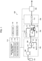
- the liquid chromatograph analyzer 100 is mainly comprised of a mobile phase tank 101, a liquid feeding unit 102 (liquid feeding part), a sample introduction unit 103 (sample introduction part), a column temperature adjustment unit 104, a detector 105, an integrated control part 114, an operating part 118, and a display part 119.
- the liquid feeding unit 102 includes, as an example, a liquid feeding apparatus 106, a pressure detector 107, a channel switching valve 108, a liquid feeding channel C0, an analysis channel C1, and a drainage channel C2.
- the liquid feeding apparatus 106 has the function to suck the mobile phase for use in transportation and separation of a sample, from the mobile phase tank 101 and compress it at high pressure and discharge it.
- the liquid feeding unit 102 can be configured as a liquid chromatograph system that can feed one or a plurality of mobile phases from one liquid feeding apparatus 106.
- the pressure detector 107 is a sensor device that detects the pressure in the liquid feeding channel C0 for feeding the mobile phase in the liquid feeding unit 102, and in the pipe up to the detector.
- the channel switching valve 108 is connected downstream of the liquid feeding apparatus 106 and has the function to selectively connect the liquid feeding channel C0 to either the analysis channel C1 connected to the sample introduction unit 103 or the drainage channel C2.
- the channel switching valve 108 is configured to be able to provide a tight stopper state in which no connection is performed to any of the analysis channel C1 and the drainage channel C2, when a pressure test is performed, which will be described later.
- the sample introduction unit 103 is mainly comprised of a sample introduction valve 109, a sample metering pump 110, and a needle 111.
- the sample introduction valve 109 is connected to the analysis channel C1 and has the switching function to introduce the sample discharged by the sample metering pump into the analysis channel C3 while introducing the mobile phase into the analysis channel C3 downstream.
- the sample introduction valve 109 has a sample inlet 112 for introducing sample.
- the sample metering pump 110 has the function to discharge the sample as the object of measurement into the sample inlet 112 through the needle 111.
- the sample introduced from the sample metering pump 110 into the sample introduction valve 109 is mixed with the mobile phase and discharged to the analysis channel C3.
- the column temperature adjustment unit 104 can house a separation column 113 and has the function to control the temperature of the separation column 113 to make it constant.
- the separation column 113 is connected to the sample introduction unit 103 through the analysis channel C3 and separates the sample introduced from the sample introduction unit 103 by the mobile phase, into components.
- the detector 105 is connected downstream of the column temperature adjustment unit 104 and has the function to detect the components separated in the separation column 113.
- the integrated control part 114 is a control part to control the liquid feeding unit 102, sample introduction unit 103, column temperature adjustment unit 104, and detector 105 to acquire liquid chromatograph data and control operation for a pressure test.
- the integrated control part 114 includes, as an example, an analysis condition setting part 115 for setting the analysis condition to control the abovementioned units 102 to 104, a data processing part 116 for analyzing the analysis result output from the detector 105, and an analysis control part 117 for outputting the timing to start each analysis, etc. to the units 102 to 104.
- the operating part 118 is a device that includes, for example, input devices such as a keyboard, ten key, and mouse and enables the user to enter various instructions relating to control by the integrated control part 114.
- the display part 119 is a device to display the analysis condition and the analysis result and can be constituted, for example, by a liquid crystal display, organic EL display or the like.
- Fig. 2 shows an example of the configuration and operation of the channel switching valve 108.
- the channel switching valve 108 includes three pipe joints 201A to C and a movable channel 202 to connect two of the three pipe joints 201A to C.
- the pipe joint 201A can be, for example, connected to the liquid feeding channel C0
- the pipe joint 201B can be connected to the analysis channel C1
- the pipe joint 201C can be, for example, connected to the drainage channel C2.
- the movable channel 202 is configured to be able to rotate around the pipe joint 201A with one end connected to the pipe joint 201A in the center.
- the other end of the movable channel 202 can be, by rotation, connected to one of the two other pipe joints, 201B and 201C (state (A) or (B) in Fig. 2 ) or unconnected to any pipe joint (state (C) in Fig. 2 ) (tight stopper state).
- the chromatograph analyzer in the first embodiment can provide not only the state (A) and state (B), but also the state (C), namely a tight stopper state in which no connection is performed to any of the analysis channel C1 and the drainage channel C2. Given this state (C), it is possible to provide the tight stopper function to perform an automatic pressure test. By providing the tight stopper state in a conventional channel switching valve, a pressure test can be performed without adding a special component.
- Fig. 3 shows an example of the configuration and operation of the sample introduction valve 109.
- the sample introduction valve 109 is comprised of six pipe joints 301A to F and three movable channels 302A to C to connect two pipe joints among them.
- the pipe joints 301A to F are arranged along one circumference.
- the movable channels 302A to C have a curvature approximately equal to the curvature of the circumference along which the pipe joints 301A to F are arranged and are movable along the circumference.
- the movable channels 302A to C are configured so that when one end thereof is connected to the pipe joint 301A to F, the other end is connected to the adjacent pipe joint 301A to 301F (states (A) and (B) in Fig. 3 ).
- the sample is introduced from the sample metering pump 110 and in the state (A), the introduced sample is fed to the downstream side by the mobile phase.
- the sample introduction valve 109 is not connected to any of the analysis channel C1, analysis channel C3, and drainage channel C4 and the sample introduction valve 109 goes into a tight stopper state. In the tight stopper state, a pressure test can be performed.
- the sample introduction valve 109 in the first embodiment in Fig. 1 can provide not only the state (A) and state (B), but also the state (C), namely a tight stopper state in which the analysis channel C1 is connected to neither the analysis channel C nor the drainage channel C4.
- the state (C) it is possible to provide a tight stopper state to perform a pressure test and a pressure test can be performed upstream of the sample introduction valve 109.
- a pressure test can be performed without adding a special component.
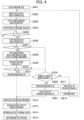
- FIG. 4 an explanation will be made of an exemplary procedure to perform a pressure test in the liquid chromatograph analyzer in the first embodiment.
- Fig. 4 an explanation is made, as an example, of the case that the channel switching valve 108 is in the tight stopper state but the procedure is the same as even in the case that the sample introduction valve 109 is in the tight stopper state.
- Step S401 As an instruction to start a pressure test is given (Step S401), the channel switching valve 108 of the liquid feeding unit 102 is switched to the tight stopper state (state (C) in Fig. 2 ) (Step S402).
- the liquid feeding apparatus 106 starts feeding the liquid until a preset flow rate is reached (Step S403).
- the pressure detector 107 in the liquid feeding unit 102 starts acquiring (tracing) the pressure value (P) (Step S404).
- the liquid feeding apparatus 106 should change the flow rate at a fixed acceleration rate or at regular time intervals in a stepwise fashion up to the set liquid feeding rate.
- Step S405 When the pressure value (P) approaches a pressure test pressure (Pset) as a set value and for example, reaches a pressure point smaller than Pset by a certain value a (Step S405), the liquid feeding apparatus 106 reduces the liquid feeding rate continuously or in a stepwise fashion in order to prevent an excessive pressure rise beyond the set pressure test pressure (Pset) (Step S406).
- Step S407 If the pressure value (P) reaches the pressure test pressure (Pset) or more (Yes at Step S407), the liquid feeding apparatus 106 stops feeding the liquid (Step S408). At this time, in order to prevent the pressure of the compressed mobile phase from activating the driving component of the liquid feeding apparatus 106, the state in which the driving component is held (holding state) is maintained. As a concrete holding method, the motor activating the driving component is stopped in an excited state so that the driving component can be held.
- the integrated control part 114 measures pressure variation ( ⁇ P) in the pressure value (P) detected by the pressure detector 107 just after the pressure test pressure (Pset) is reached (Step S409). At this time, if the variation ( ⁇ P) in pressure value (P) per given time is less than a threshold (b) (Yes at Step S410), the integrated control part 114 determines that the liquid chromatograph analyzer meets the required pressure resistance (OK) (Step S411) .
- Step S412 If it is determined that the required pressure resistance is met (OK), after the channel switching valve 108 is switched to the state (state B) in which the liquid feeding channel C0 is connected to the drainage channel C2 in order to release the pressure in the device (Step S412), the driving component holding state of the liquid feeding apparatus 106 is released (Step S413). Then, the channel switching valve 108 is returned to the state for normal analysis (A) (Step S414) and the pressure test is ended (Step S415) .
- Step S416 the purge step (bubble removal step) or the pressure resistance NG decision and subsequent step are carried out depending on the number of times of remeasurement.
- Step S416 a decision is made as to whether the number of times of remeasurement of pressure value (P) in the pressure test is not more than a prescribed number of times of repeating (m). If the number of times of remeasurement is not more than the prescribed number of times of repeating m (Yes at Step S416), a probable cause other than pressure leakage may be that bubbles may have entered the cylinder of the liquid feeding apparatus 106 that compresses and discharges the mobile phase. Therefore, the integrated control part 114 causes the liquid feeding apparatus 106 to start the purge step. In other words, if the pressure variation ( ⁇ P) is equal to or more than the threshold (b), the integrated control part 114 causes the liquid feeding apparatus 106 to repeat the purge step for the prescribed number of times of repeating (m) .
- the liquid feeding channel C0 of the channel switching valve 108 is connected to the drainage channel C2 (state B) to release the pressure in the liquid feeding channel C0 (Step S417) and then the purge step is started in the liquid feeding apparatus 106 (Step S418). After the purge step is ended, the process returns to Step S402 and subsequently the same steps as above are carried out again.
- the integrated control part 114 determines that the device as the object does not meet the pressure resistance (NG) (Step S420) and causes the display part 119 to output an alert (warning) (Step S421).
- the integrated control part 114 switches the channel switching valve 108 to obtain the state (B) in which the liquid feeding channel C0 and the drainage channel C2 are connected, to release the pressure in the device (Step S412), releases the driving component holding state (Step S413), returns the channel switching valve 108 to the state (A) as a normal analysis position (Step S414), and ends the pressure test (S415).
- Fig. 5 illustrates exemplary pressure variations during execution of a pressure test in the first embodiment.
- Fig. 5 (i) illustrates exemplary pressure variations in the case that in the pressure rise process, the pressure is increased continuously at a given flow rate after reaching the prescribed flow rate until the prescribed pressure (Pset) is reached ( Fig. 5 (i-a)).
- Pset prescribed pressure
- Fig. 5 (i-a) when the pressure is increased continuously at a given flow rate until the prescribed pressure (Pset) is reached, in some cases the pressure suddenly rises due to the time difference after reaching the prescribed pressure until the liquid feeding apparatus 106 is stopped. In such a case, an excessive load might be applied to the liquid feeding apparatus 106 or channel.
- Fig. 5 (ii) illustrates exemplary pressure variations in the case that when the pressure value (P) approaches the prescribed pressure (Pset) in the pressure rise process, the flow rate (velocity) of the mobile phase is reduced in a stepwise fashion. For example, if the pressure value (P) reaches a value smaller than the prescribed pressure (Pset) by a, reduction of the flow rate can be started. By doing so, a spike-like rise in the pressure at the time of reaching the prescribed pressure (Pset) can be suppressed.
- the method of reducing the flow rate may be to change the flow rate at a given acceleration rate as shown in Fig. 5 (ii-a) or to change the flow rate at regular time intervals in a stepwise fashion as shown in Fig. 5 (ii-b). Alternatively, a combination of the methods of changing the flow rate as shown in Fig. 5 (ii-a) and Fig. 5 (ii-b) can be applied.
- the channel switching valve 108 and the sample introduction valve 109 are configured to provide a tight stopper state in addition to the normal state, so a pressure test of the system as a whole can be performed easily without adding a complicated mechanism.
- a liquid chromatograph analyzer 100A according to the second embodiment will be described referring to Fig. 6 .
- the same elements as in the first embodiment are designated by the same reference signs and repeated description thereof is omitted.
- the liquid chromatograph analyzer 100A is mainly comprised of a mobile phase tank 101, a liquid feeding unit 102, a sample introduction unit 103, a column temperature adjustment unit 104, a detector 105, an integrated control part 114, an operating part 118, and a display part 119.
- the liquid feeding unit 102 includes two liquid feeding apparatuses 106A and 106B and the two liquid feeding apparatuses 106A and 106B are connected to different mobile phase tanks 101A and 101B.
- Pressure detectors 107A and 107B are connected to the liquid feeding channels C01 and C02 connected to the discharge ports of the liquid feeding apparatuses 106A and 106B, respectively.
- a channel switching valve 108A to selectively switch to the analysis channel or the drainage channel is provided downstream of the two liquid feeding apparatuses 106A and 106B.
- the mobile phase discharged from the channel switching valve 108A is introduced into the sample introduction unit 103 through a junction Q1.
- the configuration of the sample introduction unit 103 is the same as in the first embodiment.
- the junction Q1 is installed downstream of the channel switching valve 108A, but instead the junction Q1 can be installed upstream of the channel switching valve 108A.
- a pressure detector shared by the liquid feeding apparatuses 106A.and 106B can be installed downstream of the junction Q1 and upstream of the channel switching valve 108A.
- the column temperature adjustment unit 104 is configured to be able to house a plurality of separation columns 113A to E.
- the plural separation columns 113A to E contain fillers of different natures.
- the column temperature adjustment unit 104 has a bypass channel 120 that enables the mobile phase to be introduced into the detector 105 without passing through the separation columns 113A to E. This bypass channel 120 is arranged in parallel to the plural separation columns 113A to 113E in the column temperature adjustment unit 104.
- column switching valves 121 and 122 to selectively connect any of the separation columns 113A to E or the bypass channel 120 to the analysis channel are provided upstream and downstream of the separation columns 113A to E.
- the column switching valves 121 and 122 include a plurality of first pipe joints to be connected to the separation columns 113A to E and bypass channel 120, a second pipe joint to be connected to the analysis channel, and a movable channel to selectively connect the first and second pipe joints.
- One end of the movable channel rotates around the second pipe joint so as to be connected to one of the plural first pipe joints and thereby one of the plural separation columns or the bypass channel 120 can be connected to the analysis channel.
- the column switching valves 121 and 122 can provide not only a state in which they are connected to the plural separation columns 113A to E or the bypass channel 120, but also a state in which they are not connected to any of the separation columns 113A to E and the bypass channel 120 (tight stopper state). Since the column switching valves 121 and 122 have a structure to be able to provide a tight stopper state, a pressure test can be performed in a channel upstream of them.
- the channel switching valve 108, sample introduction valve 109 and column switching valve 121 are arranged upstream of the separation columns 113A to 113E that are put in a high pressure environment during analysis.
- the column switching valve 122 is located downstream of the separation columns 113A to 113E.
- the liquid feeding apparatus 106A or 106B can feed the mobile phase at a desired flow rate with the column switching valves 121 and 122 connected to the bypass channel 120.
- the liquid feeding pressure in the liquid chromatograph analyzer 100 except the separation columns 113A to E can be checked.
- the liquid feeding pressure can be calculated from such information as the physical property values of the mobile phase to be fed, the flow rate, and the inside diameter and length of the connected pipe, so it is possible to check whether there is a clog in the analysis channel or not.
- a liquid chromatograph analyzer 100B according to the third embodiment will be described referring to Fig. 8 .
- Fig. 8 the same elements as in the second embodiment are designated by the same reference signs as those in Fig. 6 and repeated description thereof is omitted.
- the sample introduction unit 103 in Fig. 8 is mainly comprised of a sample introduction valve 109', a sample metering pump 1101, and a needle 111.
- the mobile phase introduced from the analysis channel C1 extending from the liquid feeding unit 102 is once introduced into the sample introduction valve 109', and then again introduced into the sample introduction valve 109' through the sample metering pump 1101, needle 111, and sample inlet 112 and then introduced into the analysis channel C3.
- the sample metering pump 1101 and needle 111 are also required to have high pressure resistance.
- the column switching valve 121 of the column temperature adjustment unit 104 in a tight stopper state, it is possible to check whether or not there is a leak in the components upstream of the column switching valve 121, including the sample metering pump 1101 and needle 111.
- the order in which check for a leak and/or clog in the channels and pressure resistance tests are carried out can be arbitrarily selected.
- the order in which these are carried out can be changed by changing the order in which the valves 108', 109', 121, and 122 are switched to the tight stopper state.
- the liquid feeding unit 102 since the liquid feeding unit 102 must feed a liquid into the channels of the device, it is desirable to conduct pressure tests by increasing the pressure in the channels, after checking whether or not there is a clog in the channels, in the order from the upstream side.
- Step S801 the column switching valves 121 and 122 are connected to the bypass channel 120 (Step S802) and then the liquid feeding unit 102 starts feeding the liquid (Step S803).
- the pressure detectors 107A and 107B in the liquid feeding unit 102 start acquiring data on the pressure value (P) of the liquid feeding channels C01 and C02 and the integrated control part 114 compares the pressure value (P) with a preset specified pressure range (Step S804) . If the pressure value (P) exceeds the specified pressure range, it is determined that there is a clog in the channels and an alert is given (Step S819) .
- Step S805 operation of the liquid feeding apparatus 106A or 106B is once stopped in order to prevent a sudden pressure rise at the time of closing the valve (Step S805) and then the process goes to pressure tests of the units 102 to 104.
- Step S806 the channel switching valve 108' installed in the liquid feeding unit 102 is switched to the tight stopper state (Step S806) and a pressure test of the liquid feeding unit 102 is started (Step S807).
- the pressure value (P) detected by the pressure detectors 107A and 107B reaches the pressure test pressure (Pset)
- Step S808 calculation of leak pressure in the liquid feeding unit 102 is started and the pressure resistance is determined from pressure variations (P) at regular time intervals.
- Step S808 the same method as in the above embodiments can be adopted.
- the display part 119 or the like outputs an alert indicating pressure resistance NG for the inside of the liquid feeding unit 102 (Step S820) .
- the channel switching valve 108' is switched to the state (B) to release the pressure in the channels C01 and C02 (Step S809) and then the process goes to a pressure test of the sample introduction unit 103.
- the pressure test of the sample introduction unit 103 can also be performed almost in the same way as the process for the liquid feeding unit 102.
- the column switching valve 121 connected downstream of the sample introduction unit 103 is switched to the tight stopper state (Step S810).
- the liquid feeding unit 102 starts feeding the mobile phase.
- the pressure in the channels down to the sample introduction unit 103 rises.
- Step S812 As soon as the pressure value (P) detected by the pressure detectors 107A and 107B reaches the pressure test pressure (Pset), calculation of the pressure (P) from the liquid feeding unit 102 to the sample introduction unit 103 is started and the variation ( ⁇ P) in the pressure value (P) per given time are calculated and based on this, the pressure resistance of the sample introduction unit 103 is determined (Step S812).
- Step S820 If the sample introduction unit 103 does not meet the specification which prescribes the pressure resistance (NG), based on the fact that the pressure resistance of the liquid feeding unit 102, located immediately before it, meets the specification (OK), it is determined that there is a leak between the liquid feeding unit 102 and the sample introduction unit 103 and an alert is given (Step S820). On the other hand, if it is determined that the pressure resistance is met, the column switching valve 121 is switched for connection to the bypass channel 120 to release the pressure (Step S813). After that, the process goes to a pressure test of the column temperature adjustment unit 104.
- NG the specification which prescribes the pressure resistance
- the pressure test of the column temperature adjustment unit 104 is performed using the column switching valve 122.
- the liquid feeding unit 102 starts feeding the mobile phase and thereby pressure tests of the column temperature adjustment unit 104 and the separation columns 113A to E are started (Step S815) .
- the column switching valve 121 is connected to the separation column as the object of pressure test.
- the pressure in the channels from the liquid feeding apparatuses 106A and 106B to the column switching valve 12 rises.
- the pressure value (P) detected by the pressure detectors 107A and 107B reaches the pressure test pressure (Pset)
- calculation of the pressure from the liquid feeding unit 102 to the column switching valve 122 is started and according to the variation ( ⁇ P) in the pressure value (P) per given time, the pressure resistance of the column temperature adjustment unit 104 and the separation column as the object is determined (Step S816).
- Step S820 If the specification which prescribes the pressure resistance for the column temperature adjustment unit 104 and the like is not met (NG), based on the fact that the pressure resistances of the liquid feeding unit 102 and the sample introduction unit 103 meet the specification, it is determined that there is a leak between the column switching valve 121 and the column switching valve 122 and an alert is given (Step S820) .
- the present invention is not limited to the above embodiments but includes many variations.
- the above embodiments have been described in detail for easy understanding of the present invention; however the present invention is not limited to a structure which includes all the elements described above.
- An element of an embodiment may be replaced by an element of another embodiment or an element of an embodiment may be added to another embodiment.
- addition of another element, deletion, or replacement can be made.
Landscapes
- Physics & Mathematics (AREA)
- Health & Medical Sciences (AREA)
- Life Sciences & Earth Sciences (AREA)
- Chemical & Material Sciences (AREA)
- Analytical Chemistry (AREA)
- Biochemistry (AREA)
- General Health & Medical Sciences (AREA)
- General Physics & Mathematics (AREA)
- Immunology (AREA)
- Pathology (AREA)
- Treatment Of Liquids With Adsorbents In General (AREA)
- Sampling And Sample Adjustment (AREA)
Applications Claiming Priority (2)
| Application Number | Priority Date | Filing Date | Title |
|---|---|---|---|
| JP2019032872 | 2019-02-26 | ||
| PCT/JP2020/007598 WO2020175510A1 (ja) | 2019-02-26 | 2020-02-26 | 液体クロマトグラフ分析装置、及びその制御方法 |
Publications (3)
| Publication Number | Publication Date |
|---|---|
| EP3933399A1 EP3933399A1 (en) | 2022-01-05 |
| EP3933399A4 EP3933399A4 (en) | 2022-11-16 |
| EP3933399B1 true EP3933399B1 (en) | 2024-11-20 |
Family
ID=72239933
Family Applications (1)
| Application Number | Title | Priority Date | Filing Date |
|---|---|---|---|
| EP20762355.4A Active EP3933399B1 (en) | 2019-02-26 | 2020-02-26 | Liquid chromatographic analyzer and control method thereof |
Country Status (5)
| Country | Link |
|---|---|
| US (1) | US12298283B2 (https=) |
| EP (1) | EP3933399B1 (https=) |
| JP (1) | JP7351897B2 (https=) |
| CN (1) | CN113454450B (https=) |
| WO (1) | WO2020175510A1 (https=) |
Families Citing this family (4)
| Publication number | Priority date | Publication date | Assignee | Title |
|---|---|---|---|---|
| JP7444036B2 (ja) * | 2020-12-01 | 2024-03-06 | 株式会社島津製作所 | モニタリングシステム |
| US20240192180A1 (en) * | 2021-04-14 | 2024-06-13 | Hitachi High-Tech Corporation | Automatic analyzer including hplc and control method for the same |
| JPWO2024080246A1 (https=) * | 2022-10-14 | 2024-04-18 | ||
| CN120019274A (zh) * | 2022-10-31 | 2025-05-16 | 株式会社日立高新技术 | 液相色谱仪的控制方法以及液相色谱仪 |
Family Cites Families (29)
| Publication number | Priority date | Publication date | Assignee | Title |
|---|---|---|---|---|
| US2972246A (en) * | 1958-05-19 | 1961-02-21 | Phillips Petroleum Co | Chromatographic analyzer |
| US3892531A (en) * | 1973-07-05 | 1975-07-01 | Beckman Instruments Inc | Apparatus for sequencing peptides and proteins |
| US4059009A (en) * | 1976-09-10 | 1977-11-22 | Micromeritics Instrument Corporation | Liquid chromatography system |
| JP2504356B2 (ja) * | 1992-04-09 | 1996-06-05 | 株式会社島津製作所 | 示差屈折計 |
| EP0723152A2 (en) * | 1995-01-23 | 1996-07-24 | Hewlett-Packard Company | Method and apparatus for detector ignition |
| JP3603506B2 (ja) * | 1996-11-01 | 2004-12-22 | 株式会社島津製作所 | 液体クロマトグラフのオートインジェクタ |
| ATE419911T1 (de) * | 1999-04-23 | 2009-01-15 | Advion Biosystems Inc | Parallel ausgeführte flüssigkeitschromatographievorrichtung mit hohem durchsatz |
| JP4451067B2 (ja) * | 2001-03-02 | 2010-04-14 | ウォーターズ・インヴェストメンツ・リミテッド | 流体漏れの有無を決定する方法及び装置 |
| US6805799B2 (en) * | 2002-12-21 | 2004-10-19 | Qi-Feng Ma | Simulated moving bed chromatographic focusing |
| GB2434003B (en) * | 2004-03-05 | 2008-09-24 | Waters Investments Ltd | Pressure monitor optimization of fluid path utilization |
| JP2005257609A (ja) | 2004-03-15 | 2005-09-22 | Shimadzu Corp | 液体クロマトグラフ装置 |
| US7460958B2 (en) * | 2004-10-07 | 2008-12-02 | E.I. Du Pont De Nemours And Company | Computer-implemented system and method for analyzing mixtures of gases |
| EP1589336A1 (en) | 2005-02-04 | 2005-10-26 | Agilent Technologies, Inc. | Leakage checking and calibration of a liquid delivery system |
| JP5028109B2 (ja) * | 2007-02-28 | 2012-09-19 | 株式会社日立ハイテクノロジーズ | 液体クロマトグラフ装置 |
| EP2244091B8 (en) * | 2009-04-21 | 2016-02-24 | Agilent Technologies, Inc. | Leak detection upstream of a mixing point |
| WO2010139359A1 (en) | 2009-06-03 | 2010-12-09 | Agilent Technologies, Inc. | Sample injector with metering device balancing pressure differences in an intermediate valve state |
| JP5249908B2 (ja) * | 2009-11-06 | 2013-07-31 | 株式会社日立ハイテクノロジーズ | 液体クロマトグラフ装置 |
| US9417219B2 (en) | 2009-11-16 | 2016-08-16 | Agilent Technologies, Inc. | Sample separation device with valve |
| JP2012047655A (ja) * | 2010-08-30 | 2012-03-08 | Hitachi Ltd | 液体クロマトグラフ装置及び分析方法 |
| US10054569B2 (en) * | 2010-10-29 | 2018-08-21 | Thermo Finnigan Llc | Method and system for liquid chromatography fluidic monitoring |
| EP2632561B1 (en) | 2010-10-29 | 2017-09-20 | Thermo Finnigan LLC | Method and system for liquid chromatograph with compressibility and viscosity monitoring to identify fluids |
| US9228982B2 (en) * | 2011-09-16 | 2016-01-05 | Agilent Technologies, Inc. | Single injection valve for HPLC combining sample introduction, wash cycles and diagnosis |
| DE102011087935B4 (de) * | 2011-12-07 | 2020-01-02 | Agilent Technologies Inc. | Spülventil für Hochdruckpumpe im Niedrigflussbetrieb |
| WO2013086281A1 (en) * | 2011-12-09 | 2013-06-13 | Waters Technologies Corporation | Select valve for liquid chromatography systems |
| JP5270771B2 (ja) * | 2012-02-03 | 2013-08-21 | 株式会社日立ハイテクノロジーズ | 液体クロマトグラフ装置及び試料導入装置 |
| JP2015052533A (ja) * | 2013-09-06 | 2015-03-19 | 株式会社日立製作所 | クロマトグラフィー装置およびクロマトグラフィー方法 |
| WO2015189927A1 (ja) * | 2014-06-11 | 2015-12-17 | 株式会社島津製作所 | 液体試料導入装置 |
| DE102016121512A1 (de) | 2016-11-10 | 2018-05-17 | Dionex Softron Gmbh | System, Verfahren und Verwendung der Flüssigkeitschromatografie |
| WO2018207295A1 (ja) * | 2017-05-10 | 2018-11-15 | 株式会社島津製作所 | 送液装置及びその送液装置を備えた液体クロマトグラフ |
-
2020
- 2020-02-26 US US17/433,884 patent/US12298283B2/en active Active
- 2020-02-26 JP JP2021502293A patent/JP7351897B2/ja active Active
- 2020-02-26 CN CN202080015451.6A patent/CN113454450B/zh active Active
- 2020-02-26 EP EP20762355.4A patent/EP3933399B1/en active Active
- 2020-02-26 WO PCT/JP2020/007598 patent/WO2020175510A1/ja not_active Ceased
Also Published As
| Publication number | Publication date |
|---|---|
| JPWO2020175510A1 (https=) | 2020-09-03 |
| CN113454450B (zh) | 2024-12-03 |
| WO2020175510A1 (ja) | 2020-09-03 |
| EP3933399A1 (en) | 2022-01-05 |
| CN113454450A (zh) | 2021-09-28 |
| JP7351897B2 (ja) | 2023-09-27 |
| US12298283B2 (en) | 2025-05-13 |
| EP3933399A4 (en) | 2022-11-16 |
| US20220050088A1 (en) | 2022-02-17 |
Similar Documents
| Publication | Publication Date | Title |
|---|---|---|
| EP3933399B1 (en) | Liquid chromatographic analyzer and control method thereof | |
| EP3896440B1 (en) | Liquid chromatograph mass spectrometer | |
| EP2689244B1 (en) | Valve and splitting system for multi-dimensional liquid analysis | |
| US20150121996A1 (en) | Automated Sample Injection Apparatus, Multiport Valve, and Methods of Making and Using The Same | |
| KR101802186B1 (ko) | 온라인 유중가스 분석 시스템 | |
| EP2244091A1 (en) | Leak detection upstream of a mixing point | |
| EP3642613B1 (en) | Online dilution for a liquid chromatography system using a sample metering pump | |
| EP1544612A1 (en) | Chromatography system and method for operating the same | |
| JP6437005B2 (ja) | 多次元液体分析システムにおける体積フローの調整 | |
| CN104813164A (zh) | 用于液相色谱的混合器旁路样品注射 | |
| EP3739333A1 (en) | Analysis equipment having plurality of chromatographs | |
| CN113167772A (zh) | 具有多个色谱仪的分析装置及其控制方法 | |
| US11467137B2 (en) | Liquid chromatograph and analysis execution method | |
| EP3236256A1 (en) | Liquid chromatograph | |
| US20210302396A1 (en) | Large volume sample injection for liquid chromatography | |
| EP2781916A1 (en) | Coupling module | |
| US12360087B2 (en) | Method of controlling liquid chromatograph and liquid chromatograph | |
| JPH1123557A (ja) | 液体クロマトグラフ | |
| US12601719B2 (en) | Column device | |
| JP2021110548A (ja) | 分析装置及び分析装置の使用方法 | |
| EP2626697B1 (en) | Liquid chromatography device |
Legal Events
| Date | Code | Title | Description |
|---|---|---|---|
| STAA | Information on the status of an ep patent application or granted ep patent |
Free format text: STATUS: THE INTERNATIONAL PUBLICATION HAS BEEN MADE |
|
| PUAI | Public reference made under article 153(3) epc to a published international application that has entered the european phase |
Free format text: ORIGINAL CODE: 0009012 |
|
| STAA | Information on the status of an ep patent application or granted ep patent |
Free format text: STATUS: REQUEST FOR EXAMINATION WAS MADE |
|
| 17P | Request for examination filed |
Effective date: 20210927 |
|
| AK | Designated contracting states |
Kind code of ref document: A1 Designated state(s): AL AT BE BG CH CY CZ DE DK EE ES FI FR GB GR HR HU IE IS IT LI LT LU LV MC MK MT NL NO PL PT RO RS SE SI SK SM TR |
|
| DAV | Request for validation of the european patent (deleted) | ||
| DAX | Request for extension of the european patent (deleted) | ||
| A4 | Supplementary search report drawn up and despatched |
Effective date: 20221018 |
|
| RIC1 | Information provided on ipc code assigned before grant |
Ipc: B01D 15/14 20060101ALI20221013BHEP Ipc: G01N 30/86 20060101ALI20221013BHEP Ipc: G01N 30/46 20060101ALI20221013BHEP Ipc: G01N 30/32 20060101ALI20221013BHEP Ipc: G01N 30/26 20060101AFI20221013BHEP |
|
| GRAP | Despatch of communication of intention to grant a patent |
Free format text: ORIGINAL CODE: EPIDOSNIGR1 |
|
| STAA | Information on the status of an ep patent application or granted ep patent |
Free format text: STATUS: GRANT OF PATENT IS INTENDED |
|
| RIC1 | Information provided on ipc code assigned before grant |
Ipc: B01D 15/14 20060101ALI20240705BHEP Ipc: G01N 30/86 20060101ALI20240705BHEP Ipc: G01N 30/46 20060101ALI20240705BHEP Ipc: G01N 30/32 20060101ALI20240705BHEP Ipc: G01N 30/26 20060101AFI20240705BHEP |
|
| INTG | Intention to grant announced |
Effective date: 20240717 |
|
| GRAS | Grant fee paid |
Free format text: ORIGINAL CODE: EPIDOSNIGR3 |
|
| GRAA | (expected) grant |
Free format text: ORIGINAL CODE: 0009210 |
|
| STAA | Information on the status of an ep patent application or granted ep patent |
Free format text: STATUS: THE PATENT HAS BEEN GRANTED |
|
| AK | Designated contracting states |
Kind code of ref document: B1 Designated state(s): AL AT BE BG CH CY CZ DE DK EE ES FI FR GB GR HR HU IE IS IT LI LT LU LV MC MK MT NL NO PL PT RO RS SE SI SK SM TR |
|
| REG | Reference to a national code |
Ref country code: GB Ref legal event code: FG4D |
|
| REG | Reference to a national code |
Ref country code: CH Ref legal event code: EP |
|
| REG | Reference to a national code |
Ref country code: DE Ref legal event code: R096 Ref document number: 602020041707 Country of ref document: DE |
|
| REG | Reference to a national code |
Ref country code: IE Ref legal event code: FG4D |
|
| REG | Reference to a national code |
Ref country code: LT Ref legal event code: MG9D |
|
| REG | Reference to a national code |
Ref country code: NL Ref legal event code: MP Effective date: 20241120 |
|
| PG25 | Lapsed in a contracting state [announced via postgrant information from national office to epo] |
Ref country code: HR Free format text: LAPSE BECAUSE OF FAILURE TO SUBMIT A TRANSLATION OF THE DESCRIPTION OR TO PAY THE FEE WITHIN THE PRESCRIBED TIME-LIMIT Effective date: 20241120 Ref country code: PT Free format text: LAPSE BECAUSE OF FAILURE TO SUBMIT A TRANSLATION OF THE DESCRIPTION OR TO PAY THE FEE WITHIN THE PRESCRIBED TIME-LIMIT Effective date: 20250320 Ref country code: IS Free format text: LAPSE BECAUSE OF FAILURE TO SUBMIT A TRANSLATION OF THE DESCRIPTION OR TO PAY THE FEE WITHIN THE PRESCRIBED TIME-LIMIT Effective date: 20250320 |
|
| PG25 | Lapsed in a contracting state [announced via postgrant information from national office to epo] |
Ref country code: FI Free format text: LAPSE BECAUSE OF FAILURE TO SUBMIT A TRANSLATION OF THE DESCRIPTION OR TO PAY THE FEE WITHIN THE PRESCRIBED TIME-LIMIT Effective date: 20241120 Ref country code: NL Free format text: LAPSE BECAUSE OF FAILURE TO SUBMIT A TRANSLATION OF THE DESCRIPTION OR TO PAY THE FEE WITHIN THE PRESCRIBED TIME-LIMIT Effective date: 20241120 |
|
| REG | Reference to a national code |
Ref country code: AT Ref legal event code: MK05 Ref document number: 1744001 Country of ref document: AT Kind code of ref document: T Effective date: 20241120 |
|
| PG25 | Lapsed in a contracting state [announced via postgrant information from national office to epo] |
Ref country code: BG Free format text: LAPSE BECAUSE OF FAILURE TO SUBMIT A TRANSLATION OF THE DESCRIPTION OR TO PAY THE FEE WITHIN THE PRESCRIBED TIME-LIMIT Effective date: 20241120 |
|
| PG25 | Lapsed in a contracting state [announced via postgrant information from national office to epo] |
Ref country code: ES Free format text: LAPSE BECAUSE OF FAILURE TO SUBMIT A TRANSLATION OF THE DESCRIPTION OR TO PAY THE FEE WITHIN THE PRESCRIBED TIME-LIMIT Effective date: 20241120 |
|
| PG25 | Lapsed in a contracting state [announced via postgrant information from national office to epo] |
Ref country code: NO Free format text: LAPSE BECAUSE OF FAILURE TO SUBMIT A TRANSLATION OF THE DESCRIPTION OR TO PAY THE FEE WITHIN THE PRESCRIBED TIME-LIMIT Effective date: 20250220 |
|
| PG25 | Lapsed in a contracting state [announced via postgrant information from national office to epo] |
Ref country code: LV Free format text: LAPSE BECAUSE OF FAILURE TO SUBMIT A TRANSLATION OF THE DESCRIPTION OR TO PAY THE FEE WITHIN THE PRESCRIBED TIME-LIMIT Effective date: 20241120 Ref country code: GR Free format text: LAPSE BECAUSE OF FAILURE TO SUBMIT A TRANSLATION OF THE DESCRIPTION OR TO PAY THE FEE WITHIN THE PRESCRIBED TIME-LIMIT Effective date: 20250221 Ref country code: AT Free format text: LAPSE BECAUSE OF FAILURE TO SUBMIT A TRANSLATION OF THE DESCRIPTION OR TO PAY THE FEE WITHIN THE PRESCRIBED TIME-LIMIT Effective date: 20241120 |
|
| PG25 | Lapsed in a contracting state [announced via postgrant information from national office to epo] |
Ref country code: PL Free format text: LAPSE BECAUSE OF FAILURE TO SUBMIT A TRANSLATION OF THE DESCRIPTION OR TO PAY THE FEE WITHIN THE PRESCRIBED TIME-LIMIT Effective date: 20241120 |
|
| PG25 | Lapsed in a contracting state [announced via postgrant information from national office to epo] |
Ref country code: RS Free format text: LAPSE BECAUSE OF FAILURE TO SUBMIT A TRANSLATION OF THE DESCRIPTION OR TO PAY THE FEE WITHIN THE PRESCRIBED TIME-LIMIT Effective date: 20250220 |
|
| PG25 | Lapsed in a contracting state [announced via postgrant information from national office to epo] |
Ref country code: SM Free format text: LAPSE BECAUSE OF FAILURE TO SUBMIT A TRANSLATION OF THE DESCRIPTION OR TO PAY THE FEE WITHIN THE PRESCRIBED TIME-LIMIT Effective date: 20241120 |
|
| PG25 | Lapsed in a contracting state [announced via postgrant information from national office to epo] |
Ref country code: DK Free format text: LAPSE BECAUSE OF FAILURE TO SUBMIT A TRANSLATION OF THE DESCRIPTION OR TO PAY THE FEE WITHIN THE PRESCRIBED TIME-LIMIT Effective date: 20241120 |
|
| PG25 | Lapsed in a contracting state [announced via postgrant information from national office to epo] |
Ref country code: EE Free format text: LAPSE BECAUSE OF FAILURE TO SUBMIT A TRANSLATION OF THE DESCRIPTION OR TO PAY THE FEE WITHIN THE PRESCRIBED TIME-LIMIT Effective date: 20241120 |
|
| PG25 | Lapsed in a contracting state [announced via postgrant information from national office to epo] |
Ref country code: RO Free format text: LAPSE BECAUSE OF FAILURE TO SUBMIT A TRANSLATION OF THE DESCRIPTION OR TO PAY THE FEE WITHIN THE PRESCRIBED TIME-LIMIT Effective date: 20241120 |
|
| PG25 | Lapsed in a contracting state [announced via postgrant information from national office to epo] |
Ref country code: SK Free format text: LAPSE BECAUSE OF FAILURE TO SUBMIT A TRANSLATION OF THE DESCRIPTION OR TO PAY THE FEE WITHIN THE PRESCRIBED TIME-LIMIT Effective date: 20241120 |
|
| PG25 | Lapsed in a contracting state [announced via postgrant information from national office to epo] |
Ref country code: CZ Free format text: LAPSE BECAUSE OF FAILURE TO SUBMIT A TRANSLATION OF THE DESCRIPTION OR TO PAY THE FEE WITHIN THE PRESCRIBED TIME-LIMIT Effective date: 20241120 |
|
| PG25 | Lapsed in a contracting state [announced via postgrant information from national office to epo] |
Ref country code: IT Free format text: LAPSE BECAUSE OF FAILURE TO SUBMIT A TRANSLATION OF THE DESCRIPTION OR TO PAY THE FEE WITHIN THE PRESCRIBED TIME-LIMIT Effective date: 20241120 |
|
| REG | Reference to a national code |
Ref country code: DE Ref legal event code: R097 Ref document number: 602020041707 Country of ref document: DE |
|
| PG25 | Lapsed in a contracting state [announced via postgrant information from national office to epo] |
Ref country code: SE Free format text: LAPSE BECAUSE OF FAILURE TO SUBMIT A TRANSLATION OF THE DESCRIPTION OR TO PAY THE FEE WITHIN THE PRESCRIBED TIME-LIMIT Effective date: 20241120 |
|
| PG25 | Lapsed in a contracting state [announced via postgrant information from national office to epo] |
Ref country code: MC Free format text: LAPSE BECAUSE OF FAILURE TO SUBMIT A TRANSLATION OF THE DESCRIPTION OR TO PAY THE FEE WITHIN THE PRESCRIBED TIME-LIMIT Effective date: 20241120 |
|
| PLBE | No opposition filed within time limit |
Free format text: ORIGINAL CODE: 0009261 |
|
| STAA | Information on the status of an ep patent application or granted ep patent |
Free format text: STATUS: NO OPPOSITION FILED WITHIN TIME LIMIT |
|
| REG | Reference to a national code |
Ref country code: CH Ref legal event code: PL |
|
| PG25 | Lapsed in a contracting state [announced via postgrant information from national office to epo] |
Ref country code: LU Free format text: LAPSE BECAUSE OF NON-PAYMENT OF DUE FEES Effective date: 20250226 |
|
| PG25 | Lapsed in a contracting state [announced via postgrant information from national office to epo] |
Ref country code: CH Free format text: LAPSE BECAUSE OF NON-PAYMENT OF DUE FEES Effective date: 20250228 |
|
| 26N | No opposition filed |
Effective date: 20250821 |
|
| REG | Reference to a national code |
Ref country code: BE Ref legal event code: MM Effective date: 20250228 |
|
| PG25 | Lapsed in a contracting state [announced via postgrant information from national office to epo] |
Ref country code: FR Free format text: LAPSE BECAUSE OF NON-PAYMENT OF DUE FEES Effective date: 20250228 |
|
| PG25 | Lapsed in a contracting state [announced via postgrant information from national office to epo] |
Ref country code: BE Free format text: LAPSE BECAUSE OF NON-PAYMENT OF DUE FEES Effective date: 20250228 |
|
| PG25 | Lapsed in a contracting state [announced via postgrant information from national office to epo] |
Ref country code: IE Free format text: LAPSE BECAUSE OF NON-PAYMENT OF DUE FEES Effective date: 20250226 |
|
| PGFP | Annual fee paid to national office [announced via postgrant information from national office to epo] |
Ref country code: GB Payment date: 20260219 Year of fee payment: 7 |
|
| PGFP | Annual fee paid to national office [announced via postgrant information from national office to epo] |
Ref country code: DE Payment date: 20260228 Year of fee payment: 7 |