EP3933318A1 - Haushaltsgerät mit einem verschlusselement und einer spezifisch geformten griffmulde an einer schmalseite des verschlusselements - Google Patents
Haushaltsgerät mit einem verschlusselement und einer spezifisch geformten griffmulde an einer schmalseite des verschlusselements Download PDFInfo
- Publication number
- EP3933318A1 EP3933318A1 EP21177359.3A EP21177359A EP3933318A1 EP 3933318 A1 EP3933318 A1 EP 3933318A1 EP 21177359 A EP21177359 A EP 21177359A EP 3933318 A1 EP3933318 A1 EP 3933318A1
- Authority
- EP
- European Patent Office
- Prior art keywords
- recessed grip
- bottom wall
- household appliance
- narrow side
- closure element
- Prior art date
- Legal status (The legal status is an assumption and is not a legal conclusion. Google has not performed a legal analysis and makes no representation as to the accuracy of the status listed.)
- Granted
Links
Images

Classifications
-
- F—MECHANICAL ENGINEERING; LIGHTING; HEATING; WEAPONS; BLASTING
- F25—REFRIGERATION OR COOLING; COMBINED HEATING AND REFRIGERATION SYSTEMS; HEAT PUMP SYSTEMS; MANUFACTURE OR STORAGE OF ICE; LIQUEFACTION SOLIDIFICATION OF GASES
- F25D—REFRIGERATORS; COLD ROOMS; ICE-BOXES; COOLING OR FREEZING APPARATUS NOT OTHERWISE PROVIDED FOR
- F25D23/00—General constructional features
- F25D23/02—Doors; Covers
-
- F—MECHANICAL ENGINEERING; LIGHTING; HEATING; WEAPONS; BLASTING
- F25—REFRIGERATION OR COOLING; COMBINED HEATING AND REFRIGERATION SYSTEMS; HEAT PUMP SYSTEMS; MANUFACTURE OR STORAGE OF ICE; LIQUEFACTION SOLIDIFICATION OF GASES
- F25D—REFRIGERATORS; COLD ROOMS; ICE-BOXES; COOLING OR FREEZING APPARATUS NOT OTHERWISE PROVIDED FOR
- F25D23/00—General constructional features
- F25D23/02—Doors; Covers
- F25D23/028—Details
-
- F—MECHANICAL ENGINEERING; LIGHTING; HEATING; WEAPONS; BLASTING
- F25—REFRIGERATION OR COOLING; COMBINED HEATING AND REFRIGERATION SYSTEMS; HEAT PUMP SYSTEMS; MANUFACTURE OR STORAGE OF ICE; LIQUEFACTION SOLIDIFICATION OF GASES
- F25D—REFRIGERATORS; COLD ROOMS; ICE-BOXES; COOLING OR FREEZING APPARATUS NOT OTHERWISE PROVIDED FOR
- F25D2323/00—General constructional features not provided for in other groups of this subclass
- F25D2323/02—Details of doors or covers not otherwise covered
Definitions
- One aspect of the invention relates to a household appliance with a body. At least one receiving space for food is formed in the body.
- the household appliance has a closure element. This closure element is movably arranged on the body.
- the closure element has a narrow side.
- a recessed grip is arranged in this narrow side.
- the recessed grip has a recess bottom wall.
- the closure element can have a front plate.
- This front plate is formed, for example, from sheet metal.
- segments laterally adjoining the front panel are designed as edge areas. Gripping grooves are formed in these edge areas. These grip grooves are limited, for example, by front and rear boundary walls.
- the grip grooves are each delimited by a groove base.
- the object of the present invention is to create a household appliance in which such a recessed grip formed laterally in a narrow side of the closure element is improved in terms of its usability.
- One aspect of the invention relates to a household appliance with a body.
- a receiving space in particular for food, is formed in the body.
- the household appliance has a closure element.
- the closure element is movably arranged on the body.
- the receiving space can be closed or accessed by the closure element.
- the closure element has a front side.
- the closure element has several narrow sides adjoining the front side. The front and the narrow sides are in different levels and oriented at an angle to each other.
- the narrow sides extend in the depth direction of the closure element or at least essentially in the depth direction of the closure element.
- the front side is typically rectangular, so that the closure element has four narrow sides: namely a left, a right, an upper and a lower narrow side.
- a recessed grip is arranged, in particular formed, in at least one narrow side.
- the recessed grip is preferably delimited towards the front by a front delimiting wall viewed in the depth direction. It is also possible that the recessed grip is delimited towards the rear by a rear delimitation wall viewed in the depth direction.
- the recessed grip is delimited by a recess bottom wall.
- This trough bottom wall is designed to be inclined in the depth direction of the closure element. In a plane perpendicular to the longitudinal extension of the narrow side, the trough bottom wall is thus inclined or inclined with respect to the depth direction. In this plane, the trough bottom wall does not run parallel to the depth direction.
- Such a configuration thus provides a very specific cross-sectional geometry of the recessed grip.
- the recessed grip can be enlarged individually thanks to the specifically oriented recess bottom wall.
- the recess bottom wall can also serve as a contact surface on which, for example, viewed against the depth direction, a force can be exerted by one or more fingers that engage in the recessed grip. Pulling on the closure element can thus be improved by engaging the recessed grip. It is no longer just necessary for a corresponding force to be exerted on, for example, a front boundary wall.
- this orientation of the recess bottom wall enables deeper engagement with one or more fingers in the recessed grip.
- this orientation of the trough bottom wall is that one of the two possible boundary walls is more or less extended in this horizontal plane compared to the prior art. As a result, this boundary wall can be used in an improved manner for equipping with other components compared to the prior art.
- a household appliance with a body in which a receiving space is formed has a closure element which is movably arranged on the body.
- the receiving space can be closed or accessed by the closure element.
- the closure element has a front side and several narrow sides adjoining it.
- the front and the narrow sides are oriented in different planes and at an angle to one another.
- a recessed grip is formed in at least one of these narrow sides.
- the recessed grip is preferably delimited towards the front by a front delimiting wall viewed in the depth direction. It is also possible that the recessed grip is delimited towards the rear by a rear delimitation wall viewed in the depth direction.
- the recessed grip always has a recess bottom wall by which the recessed grip is delimited.
- Each narrow side has a longitudinal extension, i.e. an extension of the narrow side which is at a maximum compared to the other extensions of the narrow side.
- the trough bottom wall In a plane perpendicular to that of the longitudinal extension of the narrow side, the trough bottom wall has a first end and a second end. In this plane, the trough bottom wall extends between the first end and the second end. If this plane is a horizontal plane (recessed grip on the left or right narrow side), according to this aspect of the invention, the first end is arranged in a different width position relative to the second end.
- this plane is a vertical plane (recessed grip in the upper or lower narrow side)
- the first end is arranged in a different height position relative to the second end.
- the trough bottom wall is arranged inclined in the depth direction of the closure element. This means that the recess bottom wall is not oriented parallel to the depth direction in a plane oriented perpendicular to the longitudinal extension of the recessed grip. Rather, the trough bottom wall is arranged in this plane inclined to this depth direction.
- the household appliance has a body.
- a receiving space is formed in the body, in particular for receiving food.
- the household appliance has a closure element which is movably arranged on the body.
- the receiving space can be closed or accessed by the closure element.
- the closure element has a front side and several narrow sides adjoining it. In this aspect too, the front and the narrow sides are oriented in different planes and at an angle to one another.
- a recessed grip is formed in at least one of these narrow sides. The recessed grip is delimited towards the front by a front delimitation wall viewed in the depth direction. The recessed grip is limited to the rear by a rear delimitation wall viewed in the depth direction.
- the recessed grip has a recess bottom wall by which the recessed grip is also delimited.
- the trough bottom wall preferably adjoins the front and rear delimitation walls.
- Each narrow side has a longitudinal extension, i.e. an extension of the narrow side which is at a maximum compared to the other extensions of the narrow side.
- An interior angle which is thus dimensioned in the recessed grip and is thus dimensioned between the inner sides of the walls of the recessed grip, and which is formed between the recess bottom wall and the front boundary wall, is different from an interior angle between the recess bottom wall and the rear boundary wall.
- these above-mentioned aspects and advantageous embodiments apply to at least 50 percent or at least 70 percent or at least 80 percent or at least 90 percent of the length of the recessed grip and / or along the longitudinal extension of the recessed grip.
- the length of the recessed grip or the longitudinal extension of the recessed grip is the largest extension of the recessed grip.
- the longitudinal extension of the recessed grip runs parallel to the longitudinal extension of the narrow side.
- a first end of the trough bottom wall in Width direction or height direction viewed by a maximum of 2 cm, in particular a maximum of 1 cm, in particular a maximum of 0.7 cm, in particular a maximum of 0.5 cm with respect to a second end of the trough bottom wall is arranged offset.
- they are offset from one another between 0.3 cm and 0.5 cm, in particular 0.4 cm.
- This distance to a line parallel to the depth direction is dimensioned in the width direction or height direction, depending on whether the plane is a horizontal plane (width direction) or a vertical plane (height direction).
- the recess bottom wall is shorter than a rear delimitation wall of the recessed grip and / or is shorter than a front delimitation wall of the recessed grip.
- the recessed grip is designed to be relatively small or relatively narrow at its trough bottom.
- the recessed grip can also be designed in an ergonomically improved manner for intervention.
- other installation space of the closure element, which is filled with a thermally insulating material, is enlarged as a result. The insulating effect of the closure element is thus improved.
- the trough bottom wall is curved at least in sections in a plane that is perpendicular to a longitudinal extension of the narrow side.
- the recess bottom wall can be curved convexly or concavely, at least in sections, i.e. cambered towards a recess entrance of the recessed grip or cambered away from a recess entrance of the recessed grip.
- the trough bottom wall runs completely curved in this plane between a first end of the trough bottom wall and a second end of the trough bottom wall.
- the trough bottom wall in a plane which is perpendicular to a longitudinal extension of the narrow side, is at least partially straight.
- the trough bottom wall runs completely in a straight line in this plane between a first end of the trough bottom wall and a second end of the trough bottom wall.
- This is another very advantageous embodiment.
- this results in a simple geometry of the trough bottom wall.
- the recessed grip on this floor can be designed accordingly with regard to its width.
- a rectilinear design of the trough bottom wall also particularly promotes the advantages that can be achieved in the above-mentioned independent aspects.
- the trough bottom wall is inclined at an interior angle between 5 ° and 45 °, in particular between 15 ° and 40 °, to the depth direction. This can be seen in particular in the plane perpendicular to the longitudinal extent of the narrow side.
- the trough bottom wall is designed to be sloping in the depth direction. This means that in a plane perpendicular to a longitudinal extension of the narrow side, a rear end of the trough bottom wall (first end) viewed in the depth direction of the closure element is further spaced from a trough entrance of the recessed grip than a front end of the trough bottom wall (second) viewed in the depth direction of the closing element End).
- the recessed grip is thus enlarged in the bottom area of the recessed grip, viewed in the depth direction towards the rear, in particular enlarged in the width direction or height direction.
- an interior angle between the rear boundary wall and the trough bottom wall differs from an interior angle between the trough bottom wall and the front boundary wall.
- the interior angle between the rear boundary wall and the trough bottom wall is smaller than the interior angle between the trough bottom wall and the front boundary wall.
- the front delimiting wall and the trough bottom wall are formed in one piece. If a rear delimitation wall is present, it can be provided that the front delimitation wall, the rear delimitation wall and the trough bottom wall are formed in one piece. This can Installation effort can be saved. Interfaces that would exist between individual components can also be avoided in this way. In this way, leaks, such as, for example, the passage of contamination from the recessed grip into the interior of the closure element, can be avoided. Thermally insulating material, which is arranged in this interior space of the closure element, can also be prevented from entering the recessed grip through such interfaces.
- this narrow side of the closure element is covered by an edge cover and the recessed grip is formed in one piece with the edge cover.
- the edge cover is an edge-side visible component of the closure element. In particular, this edge covering covers the interior of the closure element laterally (left / right / top / bottom).
- the front side is formed by a front cover.
- the edge cover and the front cover are in particular formed in one piece.
- the interior of the closure element is covered on the front side by the front cover.
- the front cover forms a front-side visible component of the closure element.
- An outer shell or outer shell of the closure element is thus provided by the front cover and / or the edge cover.
- edge cover and / or the front cover are made of metal, for example sheet metal.
- the recessed grip has a rear delimiting wall and the narrow side is formed by an edge cover, with an end of the rear delimiting wall facing away from the trough bottom wall in a plane perpendicular to a longitudinal extension of the narrow side to one over its entire (within the plane dimensioned) length convex curved transition of the edge cover ends, wherein another end of the transition ends at a horizontal part of the edge cover.
- a steadily curved transition is thus created.
- This corner area of the edge cover is thus formed in a relatively small radius, which means that corresponding installation space can be saved.
- This The transition is thus formed without a section which is rectilinear.
- the "horizontal part of the edge cover" is preferably formed by a flat surface which lies in a plane spanned by the width and height of the closure element.
- this transition curved over its entire length, in particular convexly curved, is formed in such a way that an angle between 30 ° and 50 °, in particular between 35 ° and 45 °, in particular 40 °, is formed between the rear boundary wall and the horizontal part.
- the recessed grip has a rear and a front boundary wall and these are oriented towards one another in a plane perpendicular to a longitudinal extension of the narrow side, viewed from a recess entrance of the recessed grip to the recess bottom wall.
- the recessed grip is tapered towards the bottom of the recess.
- the recessed grip has a rear and a front delimitation wall and the rear delimitation wall and the front delimitation wall are each designed in a straight line in a plane perpendicular to a longitudinal extension of the narrow side.
- the recessed grip optionally with the boundary walls and the recess bottom wall, is designed as a deformed component, in particular as a flexible component.
- the recessed grip extends in the longitudinal extension of the narrow side over the entire narrow side.
- the recessed grip has a constant cross-sectional profile along at least 50%, or at least 75%, or at least 80% or at least 90% of its longitudinal extent.
- a separate functional component is arranged on an inside of the rear boundary wall.
- This Functional component can for example be at least one light source, in particular a light source array.
- this functional component is a display.
- An operating and / or display unit can also be arranged there as a functional component.
- the functional component can also have a touch-sensitive control panel.
- the recessed grip is closed on the front.
- the recessed grip can only be engaged via the narrow side in which the recessed grip is arranged or formed.
- the recessed grip does not protrude beyond the front in the width direction and / or height direction.
- the recessed grip forms an integrated handle.
- the closure element can be a door, a drawer or a drawer front or a flap.
- a "movable arrangement" of the closure element on the body is, for example, conceivable as an (exclusively) rotatable articulation of the closure element by means of hinges or an (exclusively) translatory articulation by means of (telescopic) extensions.
- the household appliance can in particular be a household refrigeration appliance, such as a refrigerator or a freezer or a fridge-freezer combination. It is also conceivable that the household appliance is an oven, a dishwasher or a washing machine.
- a household refrigeration appliance such as a refrigerator or a freezer or a fridge-freezer combination. It is also conceivable that the household appliance is an oven, a dishwasher or a washing machine.
- a household appliance 1 is shown in a schematic representation.
- the household appliance 1 is designed here for storing food.
- the household appliance 1 is a household refrigerator. It can thus be a refrigerator or a freezer or a combined refrigerator-freezer.
- the household appliance 1 has a body 2. At least one receiving space 3 is formed in the body 2.
- the receiving space 3 is designed here to receive food.
- a further, separate receiving space 4 can also be formed in addition to or instead of this.
- the receiving space 3 can be a cooling space.
- the receiving space 4 can, for example, be a freezer space. However, it can also be a second cooling room.
- the household appliance 1 also has a closure element 5.
- the closure element 5 is movably arranged on the body 2. In particular, it can be pivoted about a vertical axis A. If the household appliance 1 has a further receiving space 4, a further closure element 6 can be present. This is in particular separate from the closure element 5. In particular, the two closure elements 5 and 6 can be moved independently of one another.
- the second closure element 6 can be pivotable about a vertical axis B.
- the closure element 5 has a front side 7.
- the front side 7 is a front surface.
- the closure element 5 has an upper narrow side 8, a lower narrow side 9 and two opposite vertical narrow sides 10 and 11.
- the narrow sides 8 to 11 represent the narrow sides of the plate-like closure element 5.
- a recessed grip 12 is formed in the vertical narrow side 11. This is closed at the front and can only be accessed via this narrow side 11. This recessed grip 12 thus has only one recessed grip 12 that is open on the side in this regard. The recessed grip 12 can therefore only be engaged by engaging in the width direction (x direction).
- closure element 6 If the closure element 6 is present, it can have a further recessed grip 14 on a corresponding vertical narrow side 13.
- the recessed grips 12 and 14 extend in the longitudinal direction of the narrow sides 11 and 13 only over a section of these narrow sides 11 and 13. Alternatively, it can be provided that the recessed grips 12 and / or 14 extend over the entire length of the narrow sides 11 and 13.
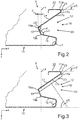
- Fig. 2 a partial element of the closure element 5 is partially shown in a sectional view.
- the level that is in Fig. 2 shown is a horizontal plane. This plane is spanned by the depth direction (z direction) of the closure element 5 and the width direction (x direction) of the closure element 5.
- the Closure element 5 has a front cover 15.
- the front side 7 is covered by this front cover 15.
- the closure element 5 has an edge cover 16.
- the narrow side 11 is covered by this edge cover 16.
- the front cover 15 represents a front-side visible component of the closure element 5.
- the edge cover 16 represents a side cover of the narrow side 11.
- the front cover 15 is made of sheet metal.
- the edge cover 16 is made of sheet metal.
- the front cover 15 and the edge cover 16 are preferably formed in one piece. In particular, these components are designed as a formed component, in particular as a bent component.
- the recessed grip 12 is delimited by a rear delimitation wall 17 in the depth direction (z-direction) and a separate front delimitation wall 18.
- the edge cover 16 is arranged at an angle ⁇ 1 to the front cover 15. The front cover 15 and the edge cover 16 thus do not extend in one plane.
- the recessed grip 12 is also delimited by a recess bottom wall 19.
- the trough bottom wall 19 is completely straight over its entire length in the horizontal plane.
- the rear delimiting wall 17 is designed to be completely straight over its entire length in this shown horizontal plane.
- the front boundary wall 18, viewed in this horizontal plane is straight over its entire length.
- the trough bottom wall 19 is at least partially cambered in this shown horizontal plane.
- the crown can be oriented in the direction of a trough entrance 20. However, it can also be oriented away from this trough entrance 20. Convex or concave curvatures of this trough bottom wall 19 can thus be provided.
- a first end 19a of the trough bottom wall 19, viewed in the width direction (x direction) is further away from a second end 19b of this trough bottom wall 19 in relation to the trough entrance 20.
- the distance between the first end 19a and the trough entrance 20 measured in the width direction is thus greater than the distance between the second end 19b and this trough entrance 20 measured in this width direction.
- the first end 19a is an end which, viewed in the depth direction, is arranged further back than the second end 19b.
- the two ends 19a and 19b are in this in Fig. 2 Horizontal plane shown, viewed in the width direction, arranged at different width positions.
- the trough bottom wall 19, viewed in this horizontal plane, is arranged at an interior angle ⁇ 2 to the rear boundary wall 17.
- the trough bottom wall 19 is arranged at an interior angle ⁇ 3 to the front boundary wall 18, viewed in this horizontal plane.
- the interior angle ⁇ 2 is smaller than the interior angle ⁇ 3.
- a corresponding angle ⁇ 4 is provided in an advantageous embodiment. This is then formed between the depth direction z in a straight line which runs through the ends 19a and 19b.
- a distance d measured in this horizontal plane perpendicular to the depth direction z, of the other end, here the first end 19a, between 2 mm and 7 mm, in particular between 2 mm and 5 mm, in particular 4 mm.
- This distance d is also in this horizontal plane, as shown in Fig. 2 shown is sized.
- the two boundary walls 17 and 18 are not oriented parallel in this horizontal plane. Starting from the trough entrance 20 to the trough bottom wall 19, they are oriented towards one another. As a result, the recessed grip 12, viewed in this horizontal plane, is tapered from the recess entrance 20 to the recess bottom.
- an end 17a of the rear boundary wall 17 facing away from the trough bottom wall 19 in this horizontal plane opens directly at a transition 21.
- This transition 21 is designed to be completely curved.
- this transition 21 is designed to be uniformly curved.
- This transition 21 preferably ends with an end 21a, which faces away from the end 17a of the rear boundary wall 17, in a horizontal part 22 of the edge cover 16.
- an angle ⁇ 5 in this horizontal plane between the boundary wall 17 and the horizontal part 22 is between 35 ° and 45 ° °, especially 40 °.
- the transition 21 is thus provided with a corresponding radius so that this angle is formed.
- the angle ⁇ 4 is preferably between 5 ° and 45 °, in particular between 15 ° and 40 °.
- this configuration allows an area of an inner side 17b of the rear delimiting wall 17 to be enlarged.
- This is the connection area for an additional separate functional component 23, as shown in FIG Fig. 3 shown is improved.
- this functional component 23 is in this horizontal plane viewed over the entire extent of this inner side 17b.
- a corresponding functional unit or functional component 23 with an individual material thickness can thereby be placed with a smaller gap. This results in a lower susceptibility to soiling.
- this configuration of the walls delimiting the recessed grip 12 also ensures that at a viewing angle ⁇ 6, as shown in FIG Fig. 3 is shown, the trough bottom or the trough bottom wall 19 is visible. This angle ⁇ 6 is smaller than in embodiments from the prior art, in which such a trough bottom wall is formed completely over its entire length in the depth direction.
Landscapes
- Engineering & Computer Science (AREA)
- Chemical & Material Sciences (AREA)
- Combustion & Propulsion (AREA)
- Physics & Mathematics (AREA)
- Mechanical Engineering (AREA)
- Thermal Sciences (AREA)
- General Engineering & Computer Science (AREA)
- Cookers (AREA)
- Refrigerator Housings (AREA)
Abstract
Description
- Ein Aspekt der Erfindung betrifft ein Haushaltsgerät mit einem Korpus. In dem Korpus ist zumindest ein Aufnahmeraum für Lebensmittel ausgebildet. Darüber hinaus weist das Haushaltsgerät ein Verschlusselement auf. Dieses Verschlusselement ist an dem Korpus bewegbar angeordnet. Das Verschlusselement weist eine Schmalseite auf. In dieser Schmalseite ist eine Griffmulde angeordnet. Die Griffmulde weist eine Muldenbodenwand auf.
- Haushaltsgeräte, wie beispielsweise Haushaltskältegeräte, sind als derartige Ausgestaltungen bekannt. In dem Zusammenhang kann das Verschlusselement eine Frontplatte aufweisen. Diese Frontplatte ist beispielsweise aus Blech ausgebildet. Darüber hinaus sind an die Frontplatte seitlich anschließende Segmente als Randbereiche ausgebildet. In diesen Randbereichen sind Griffnute ausgebildet. Diese Griffnute sind z.B. durch vordere und hintere Begrenzungswände begrenzt. Darüber hinaus sind die Griffnute jeweils durch einen Nutboden begrenzt.
- Es ist Aufgabe der vorliegenden Erfindung, ein Haushaltsgerät zu schaffen, bei welchem eine derartige seitlich in einer Schmalseite des Verschlusselements ausgebildete Griffmulde bezüglich ihrer Nutzbarkeit verbessert ist.
- Diese Aufgabe wird durch ein Haushaltsgerät, welches die Merkmale nach Anspruch 1 aufweist, gelöst.
- Ein Aspekt der Erfindung betrifft ein Haushaltsgerät mit einem Korpus. In dem Korpus ist ein Aufnahmeraum, insbesondere für Lebensmittel, ausgebildet. Darüber hinaus weist das Haushaltsgerät ein Verschlusselement auf. Die Verschlusselement ist an dem Korpus bewegbar angeordnet. Durch das Verschlusselement ist der Aufnahmeraum verschließbar bzw. zugänglich. Die Verschlusselement weist eine Frontseite auf. Darüber hinaus weist die Verschlusselement mehrere an die Frontseite anschließende Schmalseiten auf. Die Frontseite und die Schmalseiten sind in unterschiedlichen Ebenen und in einem Winkel zueinander orientiert. Die Schmalseiten erstrecken sich in Tiefenrichtung des Verschlusselements oder zumindest im Wesentlichen in Tiefenrichtung des Verschlusselements. Typischerweise ist die Frontseite rechteckig ausgebildet, so dass das Verschlusselement vier Schmalseiten aufweist: nämlich eine linke, eine rechte, eine obere und eine untere Schmalseite. In zumindest einer Schmalseite ist eine Griffmulde angeordnet, insbesondere ausgebildet. Die Griffmulde ist vorzugsweise durch eine in Tiefenrichtung betrachtet vordere Begrenzungswand nach vorne begrenzt. Möglich ist weiterhin, dass die Griffmulde durch eine in Tiefenrichtung betrachtet hintere Begrenzungswand nach hinten begrenzt ist. In jedem Fall ist die Griffmulde durch eine Muldenbodenwand begrenzt. Diese Muldenbodenwand ist in Tiefenrichtung des Verschlusselements geneigt ausgebildet. In einer zu der der Längserstreckung der Schmalseite senkrecht stehenden Ebene ist die Muldenbodenwand somit geneigt bzw. schräg gestellt gegenüber der Tiefenrichtung angeordnet. Die Muldenbodenwand verläuft in dieser Ebene nicht parallel zur Tiefenrichtung.
- Durch eine derartige Ausgestaltung wird somit eine ganz spezifische Querschnittgeometrie der Griffmulde bereitgestellt. Durch die diesbezüglich spezifisch orientierte Muldenbodenwand kann die Griffmulde individuell vergrößert werden. Dadurch ist einerseits das Eingreifen mit Fingern verbessert ermöglicht. Insbesondere kann somit in dem Zusammenhang die Muldenbodenwand auch bereits als Anlagefläche dienen, auf welche z.B. entgegen der Tiefenrichtung betrachtet eine Kraft durch einen oder mehrere Finger, die in die Griffmulde eingreifen, ausgeübt werden kann. Es kann somit ein Ziehen an dem Verschlusselement durch Eingriff in die Griffmulde verbessert werden. Es muss nicht mehr nur eine entsprechende Krafteinwirkung auf z.B. eine vordere Begrenzungswand erfolgen. Darüber hinaus ist durch diese Orientierung der Muldenbodenwand ein tieferer Eingriff mit einem oder mehreren Fingern in die Griffmulde ermöglicht. Dadurch ist das Herausrutschen der Finger aus der Griffmulde verbessert vermieden. Ein weiterer besonderer Vorteil durch diese Orientierung der Muldenbodenwand ist dahingehend gegeben, dass eine der beiden möglichen Begrenzungswände im Vergleich zum Stand der Technik in dieser Horizontalebene quasi verlängert ist. Dadurch kann diese Begrenzungswand im Vergleich zum Stand der Technik verbessert für die Bestückung mit anderen Komponenten genutzt werden.
- In einem weiteren unabhängigen Aspekt ein Haushaltsgerät mit einem Korpus, in dem ein Aufnahmeraum ausgebildet ist, vorgeschlagen ist. Das Haushaltsgerät weist ein Verschlusselement auf, das an dem Korpus bewegbar angeordnet ist. Durch das Verschlusselement ist der Aufnahmeraum verschließbar bzw. zugänglich. Das Verschlusselement weist eine Frontseite und mehrere daran anschließende Schmalseiten auf. Die Frontseite und die Schmalseiten sind auch bei diesem Aspekt in unterschiedlichen Ebenen und in einem Winkel zueinander orientiert. In zumindest einer dieser Schmalseiten ist eine Griffmulde ausgebildet. Die Griffmulde ist vorzugsweise durch eine in Tiefenrichtung betrachtet vordere Begrenzungswand nach vorne begrenzt. Möglich ist weiterhin, dass die Griffmulde durch eine in Tiefenrichtung betrachtet hintere Begrenzungswand nach hinten begrenzt ist. Die Griffmulde weist in jedem Fall eine Muldenbodenwand auf, durch welche die Griffmulde begrenzt ist. Jede Schmalseite weist eine Längserstreckung auf, d.h. eine Erstreckung der Schmalseite, die gegenüber den sonstigen Erstreckungen der Schmalseite, maximal ist. In einer zu der der Längserstreckung der Schmalseite senkrecht stehenden Ebene weist die Muldenbodenwand ein erstes Ende und ein zweites Ende auf. In dieser Ebene erstreckt sich die Muldenbodenwand zwischen dem ersten Ende und dem zweiten Ende. Sofern diese Ebene eine Horizontalebene ist (Griffmulde in linker oder rechter Schmalseite), ist gemäß diesem Aspekt der Erfindung das erste Ende gegenüber dem zweiten Ende in einer unterschiedlichen Breitenposition angeordnet. Sofern diese Ebene eine Vertikalebene ist (Griffmulde in oberer oder unterer Schmalseite), ist gemäß diesem Aspekt der Erfindung das erste Ende gegenüber dem zweiten Ende in einer unterschiedlichen Höhenposition angeordnet. Für diesen Aspekt sind die entsprechenden Vorteile, wie sie beim oben genannten ersten unabhängigen Aspekt eines Haushaltsgeräts genannt wurden, ebenfalls zutreffend.
- Zu diesem zweiten unabhängigen Aspekt ist insbesondere vorgesehen, dass die Muldenbodenwand in Tiefenrichtung des Verschlusselements geneigt angeordnet ist. Dies bedeutet, dass die Muldenbodenwand in einer senkrecht zur Längserstreckung der Griffmulde orientierten Ebene nicht parallel zur Tiefenrichtung orientiert ist. Vielmehr ist die Muldenbodenwand in dieser Ebene schräg gestellt zu dieser Tiefenrichtung angeordnet.
- In einem weiteren unabhängigen Aspekt des Haushaltsgeräts ist vorgesehen, dass dieses ein Korpus aufweist. In dem Korpus ist ein Aufnahmeraum ausgebildet, insbesondere zur Aufnahme von Lebensmitteln. Darüber hinaus weist das Haushaltsgerät ein Verschlusselement auf, das an dem Korpus bewegbar angeordnet ist. Durch das Verschlusselement ist der Aufnahmeraum verschließbar bzw. zugänglich. Die Verschlusselement weist eine Frontseite und mehrere daran anschließende Schmalseiten auf. Die Frontseite und die Schmalseiten sind auch bei diesem Aspekt in unterschiedlichen Ebenen und in einem Winkel zueinander orientiert. In zumindest einer dieser Schmalseiten ist eine Griffmulde ausgebildet. Die Griffmulde ist durch eine in Tiefenrichtung betrachtet vordere Begrenzungswand nach vorne begrenzt. Die Griffmulde ist durch eine in Tiefenrichtung betrachtet hintere Begrenzungswand nach hinten begrenzt. Die Griffmulde weist eine Muldenbodenwand auf, durch welche die Griffmulde ebenfalls begrenzt ist. Die Muldenbodenwand schließt vorzugsweise direkt an die vordere und an die hintere Begrenzungswand an. Jede Schmalseite weist eine Längserstreckung auf, d.h. eine Erstreckung der Schmalseite, die gegenüber den sonstigen Erstreckungen der Schmalseite, maximal ist. Ein Innenwinkel, der somit in der Griffmulde bemessen ist und somit zwischen den Innenseiten der Wände der Griffmulde bemessen ist, und der zwischen der Muldenbodenwand und der vorderen Begrenzungswand ausgebildet ist, ist unterschiedlich zu einem Innenwinkel zwischen der Muldenbodenwand und der hinteren Begrenzungswand. Diese Innenwinkel sind in der Ebene bemessen, die senkrecht zur Längserstreckung der Griffmulde orientiert ist. Durch diese Ausgestaltung der Muldenbodenwand sind die entsprechenden Vorteile, wie sie bereits zu dem eingangs genannten unabhängigen Aspekt eines Haushaltsgeräts benannt wurden, ebenso erreicht.
- Insbesondere gelten diese oben genannten Aspekte und vorteilhaften Ausführungen für zumindest 50 Prozent oder zumindest 70 Prozent oder zumindest 80 Prozent oder zumindest 90 Prozent der Länge der Griffmulde und/oder entlang der Längserstreckung der Griffmulde. Die Länge der Griffmulde bzw. die Längserstreckung der Griffmulde ist die größte Erstreckung der Griffmulde. Typischerweise verläuft die Längserstreckung der Griffmulde parallel zur Längserstreckung der Schmalseite.
- In einer Ausführungsform ist vorgesehen, dass in einer zu einer Längserstreckung der Schmalseite senkrecht stehenden Ebene ein erstes Ende der Muldenbodenwand in Breitenrichtung bzw. Höhenrichtung betrachtet um maximal 2 cm, insbesondere maximal 1 cm, insbesondere maximal 0,7 cm, insbesondere maximal 0,5 cm gegenüber einem zweiten Ende der Muldenbodenwand versetzt angeordnet ist. Insbesondere sind sie zwischen 0,3 cm und 0,5 cm, insbesondere 0,4 cm zueinander versetzt. Dieser Abstand zu einer Linie parallel zur Tiefenrichtung ist in Breitenrichtung bzw. Höhenrichtung bemessen, je nachdem, ob es sich bei der Ebene um eine Horizontalebene (Breitenrichtung) oder um eine Vertikalebene (Höhenrichtung) handelt. Durch diese spezifische Orientierung der Muldenbodenwand werden die oben genannten Vorteile besonders begünstigt.
- In einer Ausführungsform ist vorgesehen, dass in einer zu einer Längserstreckung der Schmalseite senkrecht stehenden Ebene die Muldenbodenwand kürzer ist, als eine hintere Begrenzungswand der Griffmulde und/oder kürzer ist als eine vordere Begrenzungswand der Griffmulde. Durch eine derartige Ausgestaltung wird die Griffmulde an ihrem Muldenboden relativ klein beziehungsweise relativ eng ausgebildet. Damit kann einerseits die Griffmulde auch ergonomisch für das Eingreifen verbessert gestaltet werden. Insbesondere wird anderweitiger Bauraum der Verschlusselement, der durch ein thermisch isolierendes Material gefüllt ist, dadurch vergrößert. Die Isolierwirkung der Verschlusselement ist somit verbessert.
- In einer Ausführungsform ist vorgesehen, dass in einer zu einer Längserstreckung der Schmalseite senkrecht stehenden Ebene die Muldenbodenwand zumindest abschnittsweise gekrümmt ist. Beispielsweise kann die Muldenbodenwand zumindest abschnittsweise konvex oder konkav gekrümmt sein, d.h. zu einem Muldeneingang der Griffmulde hin bombiert oder von einem Muldeneingang der Griffmulde weg bombiert sein. Denkbar ist insbesondere, dass die Muldenbodenwand in dieser Ebene vollständig zwischen einem ersten Ende der Muldenbodenwand und einem zweiten Ende der Muldenbodenwand gekrümmt verläuft.
- In einer Ausführungsform ist vorgesehen, dass in einer zu einer Längserstreckung der Schmalseite senkrecht stehenden Ebene die Muldenbodenwand zumindest abschnittsweise geradlinig ausgebildet ist. Denkbar ist insbesondere, dass die Muldenbodenwand in dieser Ebene vollständig zwischen einem ersten Ende der Muldenbodenwand und einem zweiten Ende der Muldenbodenwand geradlinig verläuft. Dies ist eine weitere sehr vorteilhafte Ausführungsform. Einerseits ist dadurch eine einfache Geometrie der Muldenbodenwand erreicht. Andererseits kann die Griffmulde an diesem Boden im Hinblick auf ihre Weite entsprechend gestaltet werden. Durch eine geradlinige Ausgestaltung der Muldenbodenwand sind auch die eingangs bei den oben genannten unabhängigen Aspekten erreichbaren Vorteile besonders begünstigt.
- In einer Ausführungsform ist vorgesehen, dass die Muldenbodenwand in einem Innenwinkel zwischen 5° und 45°, insbesondere zwischen 15° und 40°, zur Tiefenrichtung geneigt ist. Dies ist insbesondere in der senkrecht zur Längserstreckung der Schmalseite stehenden Ebene zu sehen.
- In einer Ausführungsform ist vorgesehen, dass die Muldenbodenwand in Tiefenrichtung abfallend geneigt ausgebildet ist. Das heißt, dass in einer zu einer Längserstreckung der Schmalseite senkrecht stehenden Ebene ein in Tiefenrichtung des Verschlusselements betrachtet hinteres Ende der Muldenbodenwand (erstes Ende) weiter von einem Muldeneingang der Griffmulde beabstandet ist, als ein in Tiefenrichtung des Verschlusselements betrachtet vorderes Ende der Muldenbodenwand (zweites Ende). Durch diese Ausgestaltung wird die Griffmulde somit in Tiefenrichtung nach hinten betrachtet im Bodenbereich der Griffmulde vergrößert, insbesondere in Breitenrichtung bzw. Höhenrichtung vergrößert. Die eingangs genannten Vorteile werden dadurch nochmals verstärkt.
- In einer Ausführungsform ist vorgesehen, dass in einer zu einer Längserstreckung der Schmalseite senkrecht stehenden Ebene ein Innenwinkel zwischen der hinteren Begrenzungswand und der Muldenbodenwand von einem Innenwinkel zwischen der Muldenbodenwand und der vorderen Begrenzungswand verschieden ist. Insbesondere kann vorgesehen sein, dass in dieser Ebene der Innenwinkel zwischen der hinteren Begrenzungswand und der Muldenbodenwand kleiner ist, als der Innenwinkel zwischen der Muldenbodenwand und der vorderen Begrenzungswand.
- In einer Ausführungsform ist vorgesehen, dass die vordere Begrenzungswand und die Muldenbodenwand einstückig ausgebildet sind. Sofern eine hintere Begrenzungswand vorhanden ist, kann vorgesehen sein, dass die vordere Begrenzungswand, die hintere Begrenzungswand und die Muldenbodenwand einstückig ausgebildet sind. Dadurch kann Montageaufwand eingespart werden. Ebenso können so Schnittstellen, die zwischen Einzelkomponenten vorhanden wären, vermieden werden. Dadurch können Leckagen, wie beispielsweise das Hindurchtreten von Verunreinigung von der Griffmulde in den Innenraum der Verschlusselement, vermieden werden. Ebenso kann thermisch isolierendes Material, welches in diesem Innenraum der Verschlusselement angeordnet ist, daran gehindert werden, durch derartige Schnittstellen in die Griffmulde einzutreten.
- In einer Ausführungsform ist vorgesehen, dass diese Schmalseite der Verschlusselement durch eine Randabdeckung abgedeckt ist und die Griffmulde einstückig mit der Randabdeckung ausgebildet ist. Die Randabdeckung ist in vorteilhafter Ausführung ein randseitiges Sichtbauteil des Verschlusselements. Insbesondere ist durch diese Randabdeckung der Innenraum des Verschlusselements seitlich (links/rechts/oben/unten) abgedeckt.
- In einer Ausführungsform ist vorgesehen, dass die Frontseite durch eine Frontabdeckung gebildet ist. Die Randabdeckung und die Frontabdeckung sind insbesondere einstückig ausgebildet. Durch die Frontabdeckung wird frontseitig der Innenraum des Verschlusselements abgedeckt. Insbesondere bildet die Frontabdeckung ein frontseitiges Sichtbauteil des Verschlusselements. Durch die Frontabdeckung und/oder die Randabdeckung ist somit eine Außenschale beziehungsweise Außenhülle des Verschlusselements bereitgestellt.
- Es kann vorgesehen sein, dass die Randabdeckung und/oder die Frontabdeckung aus Metall, z.B. Blech, ausgebildet sind.
- In einer Ausführungsform ist vorgesehen, dass die Griffmulde eine hintere Begrenzungswand aufweist und die Schmalseite durch eine Randabdeckung gebildet ist, wobei in einer zu einer Längserstreckung der Schmalseite senkrecht stehenden Ebene ein der Muldenbodenwand abgewandtes Ende der hinteren Begrenzungswand an einen über seine gesamte (innerhalb der Ebene bemessenen) Länge konvex gekrümmten Übergang der Randabdeckung endet, wobei ein weiteres Ende des Übergangs an ein Horizontalteil der Randabdeckung endet. Es wird somit ein stetig gekrümmter Übergang geschaffen. Damit ist dieser Eckbereich der Randabdeckung in einem relativ kleinen Radius ausgebildet, wodurch entsprechender Bauraum gespart werden kann. Dieser Übergang ist somit ohne ein Teilstück ausgebildet, welches geradlinig ist. Das "Horizontalteil der Randabdeckung" wird vorzugsweise durch eine ebene Fläche gebildet, die in einer durch die Breite und Höhe des Verschlusselements aufgespannten Ebene liegt.
- Insbesondere ist dieser über seine gesamte Länge gekrümmte, insbesondere konvex gekrümmte, Übergang so gebildet, dass zwischen der hinteren Begrenzungswand und dem Horizontalteil ein Winkel zwischen 30° und 50°, insbesondere zwischen 35° und 45°, insbesondere 40°, gebildet ist.
- In einer Ausführungsform ist vorgesehen, dass die Griffmulde eine hintere und eine vordere Begrenzungswand aufweist und diese in einer zu einer Längserstreckung der Schmalseite senkrecht stehenden Ebene betrachtet von einem Muldeneingang der Griffmulde zu der Muldenbodenwand hin aufeinander zu orientiert sind. Damit ist die Griffmulde in dieser Ebene betrachtet zum Muldenboden hin verjüngt ausgebildet.
- In einer Ausführungsform ist vorgesehen, dass die Griffmulde eine hintere und eine vordere Begrenzungswand aufweist und die hintere Begrenzungswand und die vordere Begrenzungswand in einer zu einer Längserstreckung der Schmalseite senkrecht stehenden Ebene jeweils geradlinig ausgebildet sind.
- In einer Ausführungsform ist vorgesehen, dass die Griffmulde, gegebenenfalls mit den Begrenzungswänden und der Muldenbodenwand, als Umformbauteil, insbesondere als Biegebauteil, ausgebildet ist.
- In einer Ausführungsform ist vorgesehen, dass sich die Griffmulde in Längserstreckung der Schmalseite über die komplette Schmalseite erstreckt.
- In einer Ausführungsform ist vorgesehen, dass die Griffmulde entlang zumindest 50 %, oder zumindest 75 % oder zumindest 80 % oder zumindest 90 % ihrer Längserstreckung ein konstantes Querschnittsprofil aufweist.
- In einer Ausführungsform ist vorgesehen, dass an einer Innenseite der hinteren Begrenzungswand ein dazu separates Funktionsbauteil angeordnet ist. Dieses Funktionsbauteil kann beispielsweise zumindest eine Lichtquelle, insbesondere ein Lichtquellenarray sein. Es kann jedoch auch vorgesehen sein, dass dieses Funktionsbauteil ein Display ist. Es kann auch eine Bedien- und/oder Anzeigeeinheit als Funktionsbauteil dort angeordnet sein. Das Funktionsbauteil kann auch ein berührsensitives Bedienfeld aufweisen.
- In einer Ausführungsform ist vorgesehen, dass die Griffmulde frontseitig verschlossen ist. Die Griffmulde kann nur über die Schmalseite, in welcher die Griffmulde angeordnet bzw. ausgebildet ist, eingegriffen werden. Insbesondere ragt die Griffmulde in Breitenrichtung und/oder Höhenrichtung nicht über die Frontseite hinaus. Die Griffmulde bildet einen integrierten Griff aus.
- Das Verschlusselement kann eine Tür, eine Schublade bzw. eine Schubladenfront oder eine Klappe sein. Unter einer "beweglichen Anordnung" des Verschlusselements an dem Korpus ist z.B. eine (ausschließlich) drehbare Anlenkung des Verschlusselements mittels Scharnieren oder eine (ausschließlich) translatorische Anlenkung mittels (Teleskop)Auszügen denkbar.
- Das Haushaltsgerät kann insbesondere ein Haushaltskältegerät, wie z.B. ein Kühlschrank oder ein Gefrierschrank oder eine Kühl-Gefrier-Kombination sein. Denkbar ist ebenfalls, dass das Haushaltsgerät ein Backofen, ein Geschirrspülgerät oder eine Waschmaschine ist.
- Mit Angaben "oben", "unten", "vorne", "hinten, "horizontal", "vertikal", "Tiefenrichtung", "Breitenrichtung", "Höhenrichtung" etc. sind die bei bestimmungsgemäßen Gebrauch und bestimmungsgemäßem Anordnen der Verschlusselement bzw. des Geräts gegebenen Positionen und Orientierungen angegeben.
- Weitere Merkmale der Erfindung ergeben sich aus den Ansprüchen, den Figuren und der Figurenbeschreibung. Die vorstehend in der Beschreibung genannten Merkmale und Merkmalskombinationen, sowie die nachfolgend in der Figurenbeschreibung genannten und/oder in den Figuren alleine gezeigten Merkmale und Merkmalskombinationen sind nicht nur in der jeweils angegebenen Kombination, sondern auch in anderen Kombinationen verwendbar, ohne den Rahmen der Erfindung zu verlassen. Es sind somit auch Ausführungen von der Erfindung als umfasst und offenbart anzusehen, die in den Figuren nicht explizit gezeigt und erläutert sind, jedoch durch separierte Merkmalskombinationen aus den erläuterten Ausführungen hervorgehen und erzeugbar sind. Es sind auch Ausführungen und Merkmalskombinationen als offenbart anzusehen, die somit nicht alle Merkmale eines ursprünglich formulierten unabhängigen Anspruchs aufweisen. Es sind darüber hinaus Ausführungen und Merkmalskombinationen, insbesondere durch die oben dargelegten Ausführungen, als offenbart anzusehen, die über die in den Rückbezügen der Ansprüche dargelegten Merkmalskombinationen hinausgehen oder abweichen.
- Ausführungsbeispiele der Erfindung werden nachfolgend anhand schematischer Zeichnungen näher erläutert. Es zeigen:
- Fig. 1
- eine perspektivische Darstellung eines Ausführungsbeispiels eines erfindungsgemäßen Haushaltsgeräts;
- Fig. 2
- eine Horizontalschnittdarstellung eines Teilbereichs eines Ausführungsbeispiels einer Frontabdeckung und einer Randabdeckung einer Verschlusselement des Haushaltsgeräts gemäß
Fig. 1 ; und - Fig. 3
- die Darstellung gemäß
Fig. 2 mit einer zusätzlichen Funktionseinheit in der Griffmulde. - In den Figuren werden gleiche oder funktionsgleiche Elemente mit den gleichen Bezugszeichen versehen.
- In
Fig. 1 ist in einer schematischen Darstellung ein Haushaltsgerät 1 gezeigt. Das Haushaltsgerät 1 ist hier zum Lagern von Lebensmitteln ausgebildet. Insbesondere ist das Haushaltsgerät 1 ein Haushaltskältegerät. Es kann somit ein Kühlgerät oder ein Gefriergerät oder ein Kühl-Gefrier-Kombigerät sein. Das Haushaltsgerät 1 weist ein Korpus 2 auf. In dem Korpus 2 ist zumindest ein Aufnahmeraum 3 ausgebildet. Der Aufnahmeraum 3 ist hier zur Aufnahme von Lebensmitteln ausgebildet. Es kann auch zusätzlich oder anstatt dazu ein weiterer, separater Aufnahmeraum 4 ausgebildet sein. Beispielsweise kann der Aufnahmeraum 3 ein Kühlraum sein. Der Aufnahmeraum 4 kann beispielsweise ein Gefrierraum sein. Es kann jedoch auch ein zweiter Kühlraum sein. - Das Haushaltsgerät 1 weist darüber hinaus eine Verschlusselement 5 auf. Die Verschlusselement 5 ist an dem Korpus 2 bewegbar angeordnet. Insbesondere ist sie um eine vertikale Achse A schwenkbar. Weist das Haushaltsgerät 1 einen weiteren Aufnahmeraum 4 auf, so kann eine weitere Verschlusselement 6 vorhanden sein. Diese ist insbesondere separat zur Verschlusselement 5. Insbesondere können die beiden Verschlusselementen 5 und 6 unabhängig voneinander bewegt werden. Die zweite Verschlusselement 6 kann um eine Vertikalachse B schwenkbar sein.
- Die Verschlusselement 5 weist eine Frontseite 7 auf. Die Frontseite 7 ist eine Frontfläche. Darüber hinaus weist die Verschlusselement 5 aufgrund ihrer dreidimensionalen Ausgestaltung eine obere Schmalseite 8, eine untere Schmalseite 9 und zwei gegenüberliegende vertikale Schmalseiten 10 und 11 auf. Die Schmalseiten 8 bis 11 stellen die Schmalseiten der plattenartigen Verschlusselement 5 dar. Im Ausführungsbeispiel ist in der vertikalen Schmalseite 11 eine Griffmulde 12 ausgebildet. Diese ist frontseitig verschlossen und kann nur über diese Schmalseite 11 eingegriffen werden. Diese Griffmulde 12 weist somit nur eine diesbezüglich seitlich offene Griffmulde 12 auf. Die Griffmulde 12 kann somit nur durch Eingriff in Breitenrichtung (x-Richtung) eingegriffen werden.
- Ist die Verschlusselement 6 vorhanden, kann diese an einer entsprechenden vertikalen Schmalseite 13 eine weitere Griffmulde 14 aufweisen.
- Die Griffmulden 12 und 14 erstrecken sich in Längsrichtung der Schmalseiten 11 und 13 jeweils nur über einen Teilabschnitt dieser Schmalseiten 11 und 13. Alternativ kann vorgesehen sein, dass sich die Griffmulden 12 und/oder 14 über die kompletten Längserstreckungen der Schmalseiten 11 und 13 erstrecken.
- In
Fig. 2 ist in einer Schnittdarstellung ein Teilelement der Verschlusselement 5 teilweise gezeigt. Die Ebene, die inFig. 2 gezeigt ist, ist eine Horizontalebene. Diese Ebene wird durch die Tiefenrichtung (z-Richtung) der Verschlusselement 5 und die Breitenrichtung (x-Richtung) der Verschlusselement 5 aufgespannt. Wie zu erkennen ist, weist die Verschlusselement 5 eine Frontabdeckung 15 auf. Die Frontseite 7 ist durch diese Frontabdeckung 15 abgedeckt. Darüber hinaus weist die Verschlusselement 5 eine Randabdeckung 16 auf. Durch diese Randabdeckung 16 ist die Schmalseite 11 abgedeckt. - Die Frontabdeckung 15 stellt ein frontseitiges Sichtbauteil der Verschlusselement 5 dar. Die Randabdeckung 16 stellt eine Seitenabdeckung der Schmalseite 11 dar.
- Insbesondere ist die Frontabdeckung 15 aus Blech. Insbesondere ist die Randabdeckung 16 aus Blech. Vorzugsweise sind die Frontabdeckung 15 und die Randabdeckung 16 einstückig ausgebildet. Insbesondere sind diese Bauteile als Umformbauteil, insbesondere als Biegebauteil, ausgebildet.
- Die Griffmulde 12 ist durch eine in Tiefenrichtung (z-Richtung) hintere Begrenzungswand 17 und eine dazu separate vordere Begrenzungswand 18 begrenzt. Grundsätzlich ist die Randabdeckung 16 in einem Winkel α1 zur Frontabdeckung 15 angeordnet. Die Frontabdeckung 15 und die Randabdeckung 16 erstrecken sich somit nicht in einer Ebene.
- Die Griffmulde 12 ist darüber hinaus durch eine Muldenbodenwand 19 begrenzt. Die Muldenbodenwand 19 ist im gezeigten Ausführungsbeispiel in der Horizontalebene über ihre gesamte Länge vollständig geradlinig ausgebildet. Insbesondere ist die hintere Begrenzungswand 17 in dieser gezeigten Horizontalebene über ihre gesamte Länge vollständig geradlinig ausgebildet. Insbesondere ist die vordere Begrenzungswand 18 in dieser Horizontalebene betrachtet über ihre gesamte Länge geradlinig ausgebildet.
- Es kann auch sein, dass die Muldenbodenwand 19 in dieser gezeigten Horizontalebene zumindest bereichsweise bombiert ist. Die Bombierung kann in Richtung zu einem Muldeneingang 20 orientiert sein. Sie kann jedoch auch von diesem Muldeneingang 20 weg orientiert sein. Es können somit konvexe oder konkave Krümmungen dieser Muldenbodenwand 19 vorgesehen sein.
In der inFig. 2 gezeigten Ausführung ist vorgesehen, dass ein erstes Ende 19a der Muldenbodenwand 19 in Breitenrichtung (x-Richtung) betrachtet weiter entfernt zu einem zweiten Ende 19b dieser Muldenbodenwand 19 in Bezug zum Muldeneingang 20 ist. Der in Breitenrichtung bemessene Abstand des ersten Endes 19a zum Muldeneingang 20 ist somit größer als der in dieser Breitenrichtung bemessene Abstand des zweiten Endes 19b zu diesem Muldeneingang 20. Diese Abstände und Orientierungen zueinander sind in dieser inFig. 2 gezeigten Horizontalebene zu sehen. - Insbesondere ist das erste Ende 19a ein in Tiefenrichtung betrachtet weiter hinten angeordnetes Ende als das zweite Ende 19b.
- Die beiden Enden 19a und 19b sind in dieser in
Fig. 2 gezeigten Horizontalebene in Breitenrichtung betrachtet auf unterschiedlichen Breitenpositionen angeordnet. - Insbesondere ist die Muldenbodenwand 19 in dieser Horizontalebene betrachtet in einem Innenwinkel α2 zur hinteren Begrenzungswand 17 angeordnet. Insbesondere ist die Muldenbodenwand 19 in einem Innenwinkel α3 zur vorderen Begrenzungswand 18 in dieser Horizontalebene betrachtet angeordnet. Insbesondere ist der Innenwinkel α2 kleiner als der Innenwinkel α3. Wie darüber hinaus in
Fig. 3 zu erkennen ist, ist bei dieser Ausgestaltung, bei welcher die Muldenbodenwand 19 vollständig geradlinig ausgebildet ist, in einem Winkel α4 geneigt zur Tiefenrichtung z angeordnet. - Bei einem Ausführungsbeispiel, bei welchem die Muldenbodenwand 19 nicht vollständig geradlinig ausgebildet ist, ist in vorteilhafter Ausführung ein entsprechender Winkel α4 vorgesehen. Dieser ist dann zwischen der Tiefenrichtung z bei einer Geraden, die durch die Enden 19a und 19b verläuft, gebildet.
- In einer vorteilhaften Ausführung ist vorgesehen, dass dann, wenn die Tiefenrichtung durch eine der beiden Enden 19a oder 19b verläuft, wie es in
Fig. 2 gezeigt ist, ein in dieser Horizontalebene dann senkrecht zur Tiefenrichtung z bemessener Abstand d des anderen Endes, hier des ersten Endes 19a, zwischen 2 mm und 7 mm, insbesondere zwischen 2 mm und 5 mm, insbesondere 4 mm. Dieser Abstand d ist ebenfalls in dieser Horizontalebene, wie sie inFig. 2 gezeigt ist, bemessen. - Wie darüber hinaus in
Fig. 2 zu erkennen ist, ist die hintere Begrenzungswand 17 in dieser Horizontalebene länger als die vordere Begrenzungswand 18. Indem darüber hinaus die dargelegte Orientierung der Muldenbodenwand 19 in dieser Horizontalebene vorgesehen ist, verlängert sich die hintere Begrenzungswand 17 in dieser Horizontalebene betrachtet um dasjenige Teilstück, welches von der Tiefenrichtung z bis zu dem ersten Ende 19a gebildet ist. - Insbesondere ist vorgesehen, dass die beiden Begrenzungswände 17 und 18 nicht parallel in dieser Horizontalebene orientiert sind. Sie sind ausgehend von dem Muldeneingang 20 zur Muldenbodenwand 19 hin aufeinander zu orientiert. Dadurch ist die Griffmulde 12 in dieser Horizontalebene betrachtet vom Muldeneingang 20 zum Muldenboden hin verjüngt ausgebildet.
- Es kann vorgesehen sein, dass ein der Muldenbodenwand 19 in dieser Horizontalebene abgewandtes Ende 17a der hinteren Begrenzungswand 17 direkt an einen Übergang 21 mündet. Dieser Übergang 21 ist vollständig gekrümmt ausgebildet. Insbesondere ist dieser Übergang 21 gleichmäßig gekrümmt ausgebildet. Vorzugsweise endet dieser Übergang 21 mit einem Ende 21a, welches dem Ende 17a der hinteren Begrenzungswand 17 abgewandt ist, in einem Horizontalteil 22 der Randabdeckung 16. Insbesondere beträgt ein Winkel α5 in dieser Horizontalebene zwischen der Begrenzungswand 17 und dem Horizontalteil 22 zwischen 35° und 45°, insbesondere 40°. Insbesondere ist somit der Übergang 21 mit einem entsprechenden Radius versehen, sodass dieser Winkel ausgebildet ist.
- Der Winkel α4 beträgt vorzugsweise zwischen 5° und 45°, insbesondere zwischen 15° und 40°.
- Durch die erläuterte Geometrie der Griffmulde 12, insbesondere die Anordnung der Begrenzungswände 17 und 18 sowie der Muldenbodenwand 19, ergibt sich auch eine ergonomische Kontur. Dadurch ist ein verbessertes Eingreifen mit Fingern, insbesondere mit Fingerkuppen, ermöglicht. Insbesondere dann, wenn ein Nutzer auch längere Fingernägel hat.
- Darüber hinaus lässt sich durch diese Ausgestaltung eine Fläche einer Innenseite 17b der hinteren Begrenzungswand 17 vergrößern. Damit ist die Anbindungsfläche für eine zusätzliche separate Funktionskomponente 23, wie dies in
Fig. 3 gezeigt ist, verbessert. Insbesondere dann, wenn sich diese Funktionskomponente 23 in dieser Horizontalebene betrachtet über die gesamte Erstreckung dieser Innenseite 17b anordnet. Insbesondere lässt sich dadurch eine entsprechende Funktionseinheit beziehungsweise Funktionskomponente 23 mit individueller Materialstärke mit einem geringeren Spalt platzieren. Dadurch ist eine geringere Verschmutzungsanfälligkeit erreicht. Nicht zuletzt ist durch diese Ausgestaltung von die Griffmulde 12 begrenzenden Wänden auch erreicht, dass bei einem Einblickwinkel α6, wie er inFig. 3 eingezeichnet ist, der Muldenboden beziehungsweise die Muldenbodenwand 19 sichtbar ist. Dieser Winkel α6 ist kleiner als bei Ausgestaltungen aus dem Stand der Technik, bei welchen eine derartige Muldenbodenwand vollständig über ihre gesamte Länge in Tiefenrichtung ausgebildet ist. -
- 1
- Haushaltsgerät
- 2
- Korpus
- 3
- Aufnahmeraum
- 4
- Aufnahmeraum
- 5
- Verschlusselement
- 6
- Verschlusselement
- 7
- Frontseite
- 8
- obere Schmalseite
- 9
- untere Schmalseite
- 10
- vertikale Schmalseite
- 11
- vertikale Schmalseite
- 12
- Griffmulde
- 13
- vertikale Schmalseite
- 14
- Griffmulde
- 15
- Frontabdeckung
- 16
- Randabdeckung
- 17
- hintere Begrenzungswand
- 17a
- Ende
- 17b
- Ende
- 18
- vordere Begrenzungswand
- 19
- Muldenbodenwand
- 19a
- erstes Ende
- 19b
- zweites Ende
- 20
- Muldeneingang
- 21
- Übergang
- 21a
- Ende
- 22
- Horizontalteil
- 23
- Funktionskomponente
- d
- Abstand
- x
- Breitenrichtung
- z
- Tiefenrichtung
- α1
- Winkel
- α2
- Innenwinkel
- α3
- Innenwinkel
- α4
- Winkel
- α5
- Winkel
- α6
- Einblickwinkel
- A
- Achse
- B
- Vertikalachse
Claims (15)
- Haushaltsgerät (1) mit einem Korpus (2), in dem ein Aufnahmeraum (3, 4) ausgebildet ist, und mit einem Verschlusselement (5, 6), das an dem Korpus (2) bewegbar angeordnet ist, wobei in einer Schmalseite (8, 9, 10, 11) des Verschlusselements (5, 6) eine Griffmulde (12) angeordnet ist, dadurch gekennzeichnet, dass eine Muldenbodenwand (19) der Griffmulde (12) in Tiefenrichtung (z) des Verschlusselements (5, 6) geneigt ausgebildet ist.
- Haushaltsgerät (1) nach Anspruch 1, dadurch gekennzeichnet, dass in einer zu einer Längserstreckung der Schmalseite (8, 9, 10, 11) senkrecht stehenden Ebene ein erstes Ende (19a) der Muldenbodenwand (19) in Breitenrichtung (x) bzw. Höhenrichtung (y) betrachtet um maximal 1 cm, insbesondere maximal 0,7 cm, gegenüber einem zweiten Ende (19b) der Muldenbodenwand (19) versetzt angeordnet ist.
- Haushaltsgerät (1) nach Anspruch 1 oder 2, dadurch gekennzeichnet, dass in einer zu einer Längserstreckung der Schmalseite (8, 9, 10, 11) senkrecht stehenden Ebene die Muldenbodenwand (19) kürzer ist, als eine hintere Begrenzungswand (17) der Griffmulde (12) und/oder kürzer ist als eine vordere Begrenzungswand (18) der Griffmulde (12).
- Haushaltgerät (1) nach einem der vorhergehenden Ansprüche, dadurch gekennzeichnet, dass in einer zu einer Längserstreckung der Schmalseite (8, 9, 10, 11) senkrecht stehenden Ebene die Muldenbodenwand (19) zumindest abschnittsweise gekrümmt ist.
- Haushaltsgerät (1) nach einem der Ansprüche 1 bis 3, dadurch gekennzeichnet, dass in einer zu einer Längserstreckung der Schmalseite (8, 9, 10, 11) senkrecht stehenden Ebene die Muldenbodenwand (19) zumindest abschnittsweise geradlinig ausgebildet ist.
- Haushaltsgerät (1) nach Anspruch 5, dadurch gekennzeichnet, dass die Muldenbodenwand (19) in einem Innenwinkel (α4) zwischen 5° und 45°, insbesondere zwischen 15° und 40°, zur Tiefenrichtung (z) geneigt ist.
- Haushaltsgerät (1) nach einem der vorhergehenden Ansprüche, dadurch gekennzeichnet, dass die Muldenbodenwand (19) in Tiefenrichtung (z) abfallend geneigt ausgebildet ist.
- Haushaltsgerät (1) nach einem der vorhergehenden Ansprüche, dadurch gekennzeichnet, dass in einer zu einer Längserstreckung der Schmalseite (8, 9, 10, 11) senkrecht stehenden Ebene ein erstes Ende (19a) der Muldenbodenwand (19) bezüglich einem zweiten Ende (19b) der der Muldenbodenwand (19) in Richtung eines Muldeneingangs (20) um einen Abstand (d) zwischen 2 mm und 5 mm, insbesondere zwischen 3 mm und 4 mm, versetzt angeordnet ist.
- Haushaltsgerät (1) nach einem der vorhergehenden Ansprüche, dadurch gekennzeichnet, dass eine vordere Begrenzungswand (18) der Griffmulde (12) und die Muldenbodenwand (19) einstückig ausgebildet sind, insbesondere dass die vordere Begrenzungswand (18) der Griffmulde (12), die Muldenbodenwand (19) und eine hintere Begrenzungswand (17) der Griffmulde (12) einstückig ausgebildet sind.
- Haushaltsgerät (1) nach einem der vorhergehenden Ansprüche, dadurch gekennzeichnet, dass die Schmalseite (8, 9, 10, 11) durch eine Randabdeckung (16) gebildet ist, und die Griffmulde (12) einstückig mit der Randabdeckung (16) ausgebildet ist, insbesondere eine Frontseite (7) des Verschlusselements (5, 6) durch eine Frontabdeckung (15) gebildet ist, wobei die Randabdeckung (16) und die Frontabdeckung (15) einstückig ausgebildet sind.
- Haushaltgerät (1) nach Anspruch 10, dadurch gekennzeichnet, dass die Randabdeckung (16) und/oder die Frontabdeckung (15) aus Metall, z.B. Blech, ausgebildet sind.
- Haushaltsgerät (1) nach einem der vorhergehenden Ansprüche , dadurch gekennzeichnet, dass die Griffmulde (12) eine hintere Begrenzungswand (17) aufweist und die Schmalseite (8, 9, 10, 11) durch eine Randabdeckung (16) gebildet ist, wobei in einer zu einer Längserstreckung der Schmalseite (8, 9, 10, 11) senkrecht stehenden Ebene ein der Muldenbodenwand (19) abgewandtes Ende (17a) der hinteren Begrenzungswand (17) an einen über seine gesamte Länge konvex gekrümmten Übergang (21) der Randabdeckung (16) endet, wobei ein weiteres Ende (21a) des Übergangs (21) an ein Horizontalteil (22) der Randabdeckung (16) endet.
- Haushaltsgerät (1) nach einem der vorhergehenden Ansprüche, dadurch gekennzeichnet, dass die Griffmulde (12) eine hintere Begrenzungswand (17) aufweist und in einer zu einer Längserstreckung der Schmalseite (8, 9, 10, 11) senkrecht stehenden Ebene ein Winkel (α5) zwischen der hinteren Begrenzungswand (17) und einer Haupterstreckungsebene des Verschlusselements (5, 6) zwischen 30° und 50°, insbesondere zwischen 35° und 45°, insbesondere 40°, beträgt.
- Haushaltsgerät (1) nach einem der vorhergehenden Ansprüche, dadurch gekennzeichnet, dass in einer zu einer Längserstreckung der Schmalseite (8, 9, 10, 11) senkrecht stehenden Ebene eine vordere Begrenzungswand (18) der Griffmulde (12) und eine hintere Begrenzungswand (17) der Griffmulde (12) von einem Muldeneingang (20) zu der Muldenbodenwand (19) hin aufeinander zu orientiert sind und/oder die hintere Begrenzungswand (17) und die vordere Begrenzungswand (18) in dieser Ebene betrachtet jeweils geradlinig ausgebildet sind.
- Haushaltsgerät (1) nach einem der vorhergehenden Ansprüche, dadurch gekennzeichnet, dass die Griffmulde (12) als Umformbauteil, insbesondere Biegebauteil, ausgebildet ist.
Applications Claiming Priority (1)
| Application Number | Priority Date | Filing Date | Title |
|---|---|---|---|
| DE102020208158.1A DE102020208158A1 (de) | 2020-06-30 | 2020-06-30 | Haushaltsgerät mit einem Verschlusselement und einer spezifisch geformten Griffmulde an einer Schmalseite des Verschlusselements |
Publications (2)
| Publication Number | Publication Date |
|---|---|
| EP3933318A1 true EP3933318A1 (de) | 2022-01-05 |
| EP3933318B1 EP3933318B1 (de) | 2023-10-18 |
Family
ID=76250185
Family Applications (1)
| Application Number | Title | Priority Date | Filing Date |
|---|---|---|---|
| EP21177359.3A Active EP3933318B1 (de) | 2020-06-30 | 2021-06-02 | Haushaltskältegerät mit einem verschlusselement und einer spezifisch geformten griffmulde an einer schmalseite des verschlusselements |
Country Status (3)
| Country | Link |
|---|---|
| EP (1) | EP3933318B1 (de) |
| CN (1) | CN113865238B (de) |
| DE (1) | DE102020208158A1 (de) |
Cited By (1)
| Publication number | Priority date | Publication date | Assignee | Title |
|---|---|---|---|---|
| US12442586B2 (en) | 2022-12-22 | 2025-10-14 | Whirlpool Corporation | Refrigerator appliance |
Families Citing this family (1)
| Publication number | Priority date | Publication date | Assignee | Title |
|---|---|---|---|---|
| WO2023134948A1 (en) * | 2022-01-13 | 2023-07-20 | BSH Hausgeräte GmbH | Refrigeration appliance |
Citations (10)
| Publication number | Priority date | Publication date | Assignee | Title |
|---|---|---|---|---|
| US3314196A (en) * | 1965-04-23 | 1967-04-18 | Gen Motors Corp | Insulated door |
| EP1096212A1 (de) * | 1999-10-25 | 2001-05-02 | Sharp Kabushiki Kaisha | Mechanismus zum Öffnen und Schliessen von Türen und Herstellungsverfahren dafür |
| WO2004048723A1 (en) * | 2002-11-25 | 2004-06-10 | Multibrás S.A. Eletrodomésticos | Handle arrangement for the front door of cabinets |
| EP2466234A2 (de) * | 2010-12-15 | 2012-06-20 | BSH Bosch und Siemens Hausgeräte GmbH | Kühlvorrichtung mit Türarm mit Sicherheitseinrichtung |
| DE102011007318A1 (de) * | 2011-04-13 | 2012-10-18 | BSH Bosch und Siemens Hausgeräte GmbH | Teilesatz für eine Kältegerätetür |
| CN202813969U (zh) * | 2012-09-18 | 2013-03-20 | 中韩科技有限公司 | 冰箱门体照明装置 |
| DE102012200813A1 (de) * | 2012-01-20 | 2013-07-25 | BSH Bosch und Siemens Hausgeräte GmbH | Wärmedämmende Tür für ein Kältegerät |
| WO2013126946A1 (en) * | 2012-02-27 | 2013-09-06 | Electrolux Home Products Pty Limited | Appliance lighting system |
| US20180010846A1 (en) * | 2016-07-11 | 2018-01-11 | Haier Us Appliance Solutions, Inc. | Handle lighting assembly for an appliance |
| US20200056832A1 (en) * | 2018-08-20 | 2020-02-20 | Haier US Appliances Solutions, Inc. | Adjustable auxiliary lighting for an appliance |
Family Cites Families (8)
| Publication number | Priority date | Publication date | Assignee | Title |
|---|---|---|---|---|
| DE102009028786A1 (de) * | 2009-08-21 | 2011-02-24 | BSH Bosch und Siemens Hausgeräte GmbH | Tür für ein Haushaltsgerät mit Griffeinsatz |
| DE102010002465B4 (de) * | 2010-03-01 | 2017-01-05 | BSH Hausgeräte GmbH | Kältegerät, insbesondere Haushaltskältegerät |
| DE102012200812A1 (de) * | 2012-01-20 | 2013-07-25 | BSH Bosch und Siemens Hausgeräte GmbH | Kältegerät mit in der Tür angeordneter Benutzerschnittstelle |
| DE102015221885A1 (de) * | 2015-11-06 | 2017-05-24 | BSH Hausgeräte GmbH | Tür mit einem Türrahmen und einem Griffmuldenelement sowie Haushaltskältegerät mit einer derartigen Tür |
| DE102017205184A1 (de) * | 2017-03-28 | 2018-10-04 | BSH Hausgeräte GmbH | Haushaltskältegerät mit einer Gerätekomponente mit von oben greifbarer Mulde in einer schrägen Streifenfläche |
| DE102017004136A1 (de) * | 2017-05-01 | 2018-11-08 | BSH Hausgeräte GmbH | Haushaltsgerät mit Beleuchtungseinrichtung für Griffmulde |
| DE102017217632A1 (de) | 2017-10-04 | 2019-04-04 | BSH Hausgeräte GmbH | Tür für ein Haushaltskältegerät mit gleicher Montagevorrichtung in seitlichen Rinnen von gegenüberliegenden Längsseiten, sowie Haushaltskältegerät und Verfahren zum Herstellen einer Tür |
| CN110243131B (zh) * | 2018-03-07 | 2022-02-11 | 博西华电器(江苏)有限公司 | 用于家用电器的门以及家用电器 |
-
2020
- 2020-06-30 DE DE102020208158.1A patent/DE102020208158A1/de not_active Withdrawn
-
2021
- 2021-06-02 EP EP21177359.3A patent/EP3933318B1/de active Active
- 2021-06-28 CN CN202110719168.8A patent/CN113865238B/zh active Active
Patent Citations (10)
| Publication number | Priority date | Publication date | Assignee | Title |
|---|---|---|---|---|
| US3314196A (en) * | 1965-04-23 | 1967-04-18 | Gen Motors Corp | Insulated door |
| EP1096212A1 (de) * | 1999-10-25 | 2001-05-02 | Sharp Kabushiki Kaisha | Mechanismus zum Öffnen und Schliessen von Türen und Herstellungsverfahren dafür |
| WO2004048723A1 (en) * | 2002-11-25 | 2004-06-10 | Multibrás S.A. Eletrodomésticos | Handle arrangement for the front door of cabinets |
| EP2466234A2 (de) * | 2010-12-15 | 2012-06-20 | BSH Bosch und Siemens Hausgeräte GmbH | Kühlvorrichtung mit Türarm mit Sicherheitseinrichtung |
| DE102011007318A1 (de) * | 2011-04-13 | 2012-10-18 | BSH Bosch und Siemens Hausgeräte GmbH | Teilesatz für eine Kältegerätetür |
| DE102012200813A1 (de) * | 2012-01-20 | 2013-07-25 | BSH Bosch und Siemens Hausgeräte GmbH | Wärmedämmende Tür für ein Kältegerät |
| WO2013126946A1 (en) * | 2012-02-27 | 2013-09-06 | Electrolux Home Products Pty Limited | Appliance lighting system |
| CN202813969U (zh) * | 2012-09-18 | 2013-03-20 | 中韩科技有限公司 | 冰箱门体照明装置 |
| US20180010846A1 (en) * | 2016-07-11 | 2018-01-11 | Haier Us Appliance Solutions, Inc. | Handle lighting assembly for an appliance |
| US20200056832A1 (en) * | 2018-08-20 | 2020-02-20 | Haier US Appliances Solutions, Inc. | Adjustable auxiliary lighting for an appliance |
Cited By (1)
| Publication number | Priority date | Publication date | Assignee | Title |
|---|---|---|---|---|
| US12442586B2 (en) | 2022-12-22 | 2025-10-14 | Whirlpool Corporation | Refrigerator appliance |
Also Published As
| Publication number | Publication date |
|---|---|
| DE102020208158A1 (de) | 2021-12-30 |
| CN113865238B (zh) | 2023-07-14 |
| EP3933318B1 (de) | 2023-10-18 |
| CN113865238A (zh) | 2021-12-31 |
Similar Documents
| Publication | Publication Date | Title |
|---|---|---|
| DE102009026659B4 (de) | Haushaltsgerät | |
| EP3467414B1 (de) | Tür für ein haushaltskältegerät mit gleicher montagevorrichtung in seitlichen rinnen von gegenüberliegenden längsseiten, sowie haushaltskältegerät und verfahren zum herstellen einer tür | |
| EP3933318B1 (de) | Haushaltskältegerät mit einem verschlusselement und einer spezifisch geformten griffmulde an einer schmalseite des verschlusselements | |
| DE102016007854A1 (de) | Rollo und Aufnahmevorrichtung mit Rollo | |
| DE102015102390A1 (de) | Schiebe-Schwenkmechanik einer Ablage eines Möbels oder Haushaltsgerätes, Möbel und Haushaltsgerät | |
| EP2274561B1 (de) | Haushaltsgerät | |
| EP3096098B1 (de) | Haushaltskältegerät mit einem eine schwenkachse aufweisenden türseitigen lagerteil und einer ausserhalb der seitlichen griffmulde angeordneten schwenkachse | |
| WO2015007607A1 (de) | Haushaltskältegerät mit einem ablageboden und ein verschiebbar daran angeordnetes griffteil | |
| WO2012139950A2 (de) | Teilesatz für eine kältegerätetür | |
| EP2496898B1 (de) | Kältegerät und eisbereiter dafür | |
| EP2686626B1 (de) | Kältegerättür | |
| EP3758553B1 (de) | Möbel oder haushaltsgerät und verfahren zur montage einer funktionseinheit eines schubelements in einem möbel oder haushaltsgerät | |
| DE102008043811A1 (de) | Haushaltsgerät mit Lagerzapfen mit Verdrehsicherung für Lagerbuchse | |
| EP3379180B1 (de) | Haushaltsgerätevorrichtung mit einem korpus, einem verschlusselement sowie einer an dem korpus und an dem verschlusselement befestigten leitung | |
| EP2993429B1 (de) | Haushaltskältegerät mit einem korpus und einer den korpus umgebenden verkleidung mit einer eingriffsmulde | |
| DE102009028786A1 (de) | Tür für ein Haushaltsgerät mit Griffeinsatz | |
| EP2730198B1 (de) | Frontplatte für Möbel mit einem Griffelement | |
| DE202006001833U1 (de) | Kältegerät | |
| DE102009028434A1 (de) | Einbaubehälter für ein Kältegerät | |
| EP3379182B1 (de) | Haushaltskältegerät mit mehrteiliger trennplatte und aufnahmenut an einem plattenteil der trennplatte | |
| EP2754785B1 (de) | Haustür-Türblatt | |
| DE102018216336A1 (de) | Haushaltsgerätegriffvorrichtung | |
| DE102020215997A1 (de) | Haushaltsgerätevorrichtung und Haushaltsgerät | |
| DE102020208803A1 (de) | Haushaltsgerätevorrichtung mit zumindest einer Schubladenfront | |
| DE102017205178A1 (de) | Haushaltskältegerät mit einer Tür und dazu separater leistenförmiger und vertikal orientierter Frontblende sowie Anordnung |
Legal Events
| Date | Code | Title | Description |
|---|---|---|---|
| PUAI | Public reference made under article 153(3) epc to a published international application that has entered the european phase |
Free format text: ORIGINAL CODE: 0009012 |
|
| STAA | Information on the status of an ep patent application or granted ep patent |
Free format text: STATUS: THE APPLICATION HAS BEEN PUBLISHED |
|
| AK | Designated contracting states |
Kind code of ref document: A1 Designated state(s): AL AT BE BG CH CY CZ DE DK EE ES FI FR GB GR HR HU IE IS IT LI LT LU LV MC MK MT NL NO PL PT RO RS SE SI SK SM TR |
|
| B565 | Issuance of search results under rule 164(2) epc |
Effective date: 20211118 |
|
| STAA | Information on the status of an ep patent application or granted ep patent |
Free format text: STATUS: REQUEST FOR EXAMINATION WAS MADE |
|
| 17P | Request for examination filed |
Effective date: 20220705 |
|
| RBV | Designated contracting states (corrected) |
Designated state(s): AL AT BE BG CH CY CZ DE DK EE ES FI FR GB GR HR HU IE IS IT LI LT LU LV MC MK MT NL NO PL PT RO RS SE SI SK SM TR |
|
| GRAP | Despatch of communication of intention to grant a patent |
Free format text: ORIGINAL CODE: EPIDOSNIGR1 |
|
| STAA | Information on the status of an ep patent application or granted ep patent |
Free format text: STATUS: GRANT OF PATENT IS INTENDED |
|
| INTG | Intention to grant announced |
Effective date: 20230607 |
|
| GRAS | Grant fee paid |
Free format text: ORIGINAL CODE: EPIDOSNIGR3 |
|
| GRAA | (expected) grant |
Free format text: ORIGINAL CODE: 0009210 |
|
| STAA | Information on the status of an ep patent application or granted ep patent |
Free format text: STATUS: THE PATENT HAS BEEN GRANTED |
|
| AK | Designated contracting states |
Kind code of ref document: B1 Designated state(s): AL AT BE BG CH CY CZ DE DK EE ES FI FR GB GR HR HU IE IS IT LI LT LU LV MC MK MT NL NO PL PT RO RS SE SI SK SM TR |
|
| REG | Reference to a national code |
Ref country code: GB Ref legal event code: FG4D Free format text: NOT ENGLISH |
|
| REG | Reference to a national code |
Ref country code: CH Ref legal event code: EP |
|
| REG | Reference to a national code |
Ref country code: DE Ref legal event code: R096 Ref document number: 502021001723 Country of ref document: DE |
|
| REG | Reference to a national code |
Ref country code: IE Ref legal event code: FG4D Free format text: LANGUAGE OF EP DOCUMENT: GERMAN |
|
| REG | Reference to a national code |
Ref country code: LT Ref legal event code: MG9D |
|
| REG | Reference to a national code |
Ref country code: NL Ref legal event code: MP Effective date: 20231018 |
|
| PG25 | Lapsed in a contracting state [announced via postgrant information from national office to epo] |
Ref country code: NL Free format text: LAPSE BECAUSE OF FAILURE TO SUBMIT A TRANSLATION OF THE DESCRIPTION OR TO PAY THE FEE WITHIN THE PRESCRIBED TIME-LIMIT Effective date: 20231018 |
|
| PG25 | Lapsed in a contracting state [announced via postgrant information from national office to epo] |
Ref country code: GR Free format text: LAPSE BECAUSE OF FAILURE TO SUBMIT A TRANSLATION OF THE DESCRIPTION OR TO PAY THE FEE WITHIN THE PRESCRIBED TIME-LIMIT Effective date: 20240119 |
|
| PG25 | Lapsed in a contracting state [announced via postgrant information from national office to epo] |
Ref country code: IS Free format text: LAPSE BECAUSE OF FAILURE TO SUBMIT A TRANSLATION OF THE DESCRIPTION OR TO PAY THE FEE WITHIN THE PRESCRIBED TIME-LIMIT Effective date: 20240218 |
|
| PG25 | Lapsed in a contracting state [announced via postgrant information from national office to epo] |
Ref country code: LT Free format text: LAPSE BECAUSE OF FAILURE TO SUBMIT A TRANSLATION OF THE DESCRIPTION OR TO PAY THE FEE WITHIN THE PRESCRIBED TIME-LIMIT Effective date: 20231018 |
|
| PG25 | Lapsed in a contracting state [announced via postgrant information from national office to epo] |
Ref country code: ES Free format text: LAPSE BECAUSE OF FAILURE TO SUBMIT A TRANSLATION OF THE DESCRIPTION OR TO PAY THE FEE WITHIN THE PRESCRIBED TIME-LIMIT Effective date: 20231018 |
|
| PG25 | Lapsed in a contracting state [announced via postgrant information from national office to epo] |
Ref country code: LT Free format text: LAPSE BECAUSE OF FAILURE TO SUBMIT A TRANSLATION OF THE DESCRIPTION OR TO PAY THE FEE WITHIN THE PRESCRIBED TIME-LIMIT Effective date: 20231018 Ref country code: IS Free format text: LAPSE BECAUSE OF FAILURE TO SUBMIT A TRANSLATION OF THE DESCRIPTION OR TO PAY THE FEE WITHIN THE PRESCRIBED TIME-LIMIT Effective date: 20240218 Ref country code: GR Free format text: LAPSE BECAUSE OF FAILURE TO SUBMIT A TRANSLATION OF THE DESCRIPTION OR TO PAY THE FEE WITHIN THE PRESCRIBED TIME-LIMIT Effective date: 20240119 Ref country code: ES Free format text: LAPSE BECAUSE OF FAILURE TO SUBMIT A TRANSLATION OF THE DESCRIPTION OR TO PAY THE FEE WITHIN THE PRESCRIBED TIME-LIMIT Effective date: 20231018 Ref country code: BG Free format text: LAPSE BECAUSE OF FAILURE TO SUBMIT A TRANSLATION OF THE DESCRIPTION OR TO PAY THE FEE WITHIN THE PRESCRIBED TIME-LIMIT Effective date: 20240118 Ref country code: PT Free format text: LAPSE BECAUSE OF FAILURE TO SUBMIT A TRANSLATION OF THE DESCRIPTION OR TO PAY THE FEE WITHIN THE PRESCRIBED TIME-LIMIT Effective date: 20240219 |
|
| PG25 | Lapsed in a contracting state [announced via postgrant information from national office to epo] |
Ref country code: SE Free format text: LAPSE BECAUSE OF FAILURE TO SUBMIT A TRANSLATION OF THE DESCRIPTION OR TO PAY THE FEE WITHIN THE PRESCRIBED TIME-LIMIT Effective date: 20231018 Ref country code: RS Free format text: LAPSE BECAUSE OF FAILURE TO SUBMIT A TRANSLATION OF THE DESCRIPTION OR TO PAY THE FEE WITHIN THE PRESCRIBED TIME-LIMIT Effective date: 20231018 Ref country code: PL Free format text: LAPSE BECAUSE OF FAILURE TO SUBMIT A TRANSLATION OF THE DESCRIPTION OR TO PAY THE FEE WITHIN THE PRESCRIBED TIME-LIMIT Effective date: 20231018 Ref country code: NO Free format text: LAPSE BECAUSE OF FAILURE TO SUBMIT A TRANSLATION OF THE DESCRIPTION OR TO PAY THE FEE WITHIN THE PRESCRIBED TIME-LIMIT Effective date: 20240118 Ref country code: LV Free format text: LAPSE BECAUSE OF FAILURE TO SUBMIT A TRANSLATION OF THE DESCRIPTION OR TO PAY THE FEE WITHIN THE PRESCRIBED TIME-LIMIT Effective date: 20231018 Ref country code: HR Free format text: LAPSE BECAUSE OF FAILURE TO SUBMIT A TRANSLATION OF THE DESCRIPTION OR TO PAY THE FEE WITHIN THE PRESCRIBED TIME-LIMIT Effective date: 20231018 |
|
| PG25 | Lapsed in a contracting state [announced via postgrant information from national office to epo] |
Ref country code: DK Free format text: LAPSE BECAUSE OF FAILURE TO SUBMIT A TRANSLATION OF THE DESCRIPTION OR TO PAY THE FEE WITHIN THE PRESCRIBED TIME-LIMIT Effective date: 20231018 |
|
| REG | Reference to a national code |
Ref country code: DE Ref legal event code: R097 Ref document number: 502021001723 Country of ref document: DE |
|
| PG25 | Lapsed in a contracting state [announced via postgrant information from national office to epo] |
Ref country code: CZ Free format text: LAPSE BECAUSE OF FAILURE TO SUBMIT A TRANSLATION OF THE DESCRIPTION OR TO PAY THE FEE WITHIN THE PRESCRIBED TIME-LIMIT Effective date: 20231018 |
|
| PG25 | Lapsed in a contracting state [announced via postgrant information from national office to epo] |
Ref country code: SK Free format text: LAPSE BECAUSE OF FAILURE TO SUBMIT A TRANSLATION OF THE DESCRIPTION OR TO PAY THE FEE WITHIN THE PRESCRIBED TIME-LIMIT Effective date: 20231018 |
|
| PG25 | Lapsed in a contracting state [announced via postgrant information from national office to epo] |
Ref country code: SM Free format text: LAPSE BECAUSE OF FAILURE TO SUBMIT A TRANSLATION OF THE DESCRIPTION OR TO PAY THE FEE WITHIN THE PRESCRIBED TIME-LIMIT Effective date: 20231018 Ref country code: SK Free format text: LAPSE BECAUSE OF FAILURE TO SUBMIT A TRANSLATION OF THE DESCRIPTION OR TO PAY THE FEE WITHIN THE PRESCRIBED TIME-LIMIT Effective date: 20231018 Ref country code: RO Free format text: LAPSE BECAUSE OF FAILURE TO SUBMIT A TRANSLATION OF THE DESCRIPTION OR TO PAY THE FEE WITHIN THE PRESCRIBED TIME-LIMIT Effective date: 20231018 Ref country code: IT Free format text: LAPSE BECAUSE OF FAILURE TO SUBMIT A TRANSLATION OF THE DESCRIPTION OR TO PAY THE FEE WITHIN THE PRESCRIBED TIME-LIMIT Effective date: 20231018 Ref country code: EE Free format text: LAPSE BECAUSE OF FAILURE TO SUBMIT A TRANSLATION OF THE DESCRIPTION OR TO PAY THE FEE WITHIN THE PRESCRIBED TIME-LIMIT Effective date: 20231018 Ref country code: DK Free format text: LAPSE BECAUSE OF FAILURE TO SUBMIT A TRANSLATION OF THE DESCRIPTION OR TO PAY THE FEE WITHIN THE PRESCRIBED TIME-LIMIT Effective date: 20231018 Ref country code: CZ Free format text: LAPSE BECAUSE OF FAILURE TO SUBMIT A TRANSLATION OF THE DESCRIPTION OR TO PAY THE FEE WITHIN THE PRESCRIBED TIME-LIMIT Effective date: 20231018 |
|
| PLBE | No opposition filed within time limit |
Free format text: ORIGINAL CODE: 0009261 |
|
| STAA | Information on the status of an ep patent application or granted ep patent |
Free format text: STATUS: NO OPPOSITION FILED WITHIN TIME LIMIT |
|
| 26N | No opposition filed |
Effective date: 20240719 |
|
| PG25 | Lapsed in a contracting state [announced via postgrant information from national office to epo] |
Ref country code: SI Free format text: LAPSE BECAUSE OF FAILURE TO SUBMIT A TRANSLATION OF THE DESCRIPTION OR TO PAY THE FEE WITHIN THE PRESCRIBED TIME-LIMIT Effective date: 20231018 |
|
| PG25 | Lapsed in a contracting state [announced via postgrant information from national office to epo] |
Ref country code: SI Free format text: LAPSE BECAUSE OF FAILURE TO SUBMIT A TRANSLATION OF THE DESCRIPTION OR TO PAY THE FEE WITHIN THE PRESCRIBED TIME-LIMIT Effective date: 20231018 |
|
| PG25 | Lapsed in a contracting state [announced via postgrant information from national office to epo] |
Ref country code: MC Free format text: LAPSE BECAUSE OF FAILURE TO SUBMIT A TRANSLATION OF THE DESCRIPTION OR TO PAY THE FEE WITHIN THE PRESCRIBED TIME-LIMIT Effective date: 20231018 |
|
| REG | Reference to a national code |
Ref country code: CH Ref legal event code: PL |
|
| PG25 | Lapsed in a contracting state [announced via postgrant information from national office to epo] |
Ref country code: LU Free format text: LAPSE BECAUSE OF NON-PAYMENT OF DUE FEES Effective date: 20240602 |
|
| PG25 | Lapsed in a contracting state [announced via postgrant information from national office to epo] |
Ref country code: IE Free format text: LAPSE BECAUSE OF NON-PAYMENT OF DUE FEES Effective date: 20240602 |
|
| PG25 | Lapsed in a contracting state [announced via postgrant information from national office to epo] |
Ref country code: BE Free format text: LAPSE BECAUSE OF NON-PAYMENT OF DUE FEES Effective date: 20240630 Ref country code: CH Free format text: LAPSE BECAUSE OF NON-PAYMENT OF DUE FEES Effective date: 20240630 |
|
| PG25 | Lapsed in a contracting state [announced via postgrant information from national office to epo] |
Ref country code: FR Free format text: LAPSE BECAUSE OF NON-PAYMENT OF DUE FEES Effective date: 20240630 |
|
| REG | Reference to a national code |
Ref country code: BE Ref legal event code: MM Effective date: 20240630 |
|
| PGFP | Annual fee paid to national office [announced via postgrant information from national office to epo] |
Ref country code: DE Payment date: 20250630 Year of fee payment: 5 |
|
| PGFP | Annual fee paid to national office [announced via postgrant information from national office to epo] |
Ref country code: AT Payment date: 20250721 Year of fee payment: 5 |
|
| PG25 | Lapsed in a contracting state [announced via postgrant information from national office to epo] |
Ref country code: CY Free format text: LAPSE BECAUSE OF FAILURE TO SUBMIT A TRANSLATION OF THE DESCRIPTION OR TO PAY THE FEE WITHIN THE PRESCRIBED TIME-LIMIT; INVALID AB INITIO Effective date: 20210602 |
|
| PG25 | Lapsed in a contracting state [announced via postgrant information from national office to epo] |
Ref country code: FI Free format text: LAPSE BECAUSE OF FAILURE TO SUBMIT A TRANSLATION OF THE DESCRIPTION OR TO PAY THE FEE WITHIN THE PRESCRIBED TIME-LIMIT Effective date: 20231019 |
|
| GBPC | Gb: european patent ceased through non-payment of renewal fee |
Effective date: 20250602 |
|
| PG25 | Lapsed in a contracting state [announced via postgrant information from national office to epo] |
Ref country code: HU Free format text: LAPSE BECAUSE OF FAILURE TO SUBMIT A TRANSLATION OF THE DESCRIPTION OR TO PAY THE FEE WITHIN THE PRESCRIBED TIME-LIMIT; INVALID AB INITIO Effective date: 20210602 |
|
| PG25 | Lapsed in a contracting state [announced via postgrant information from national office to epo] |
Ref country code: GB Free format text: LAPSE BECAUSE OF NON-PAYMENT OF DUE FEES Effective date: 20250602 |