EP3930552B1 - Bac d'égouttage pour l'application sur un système de distribution de doses ou sur un dispositif de fixation de récipient - Google Patents
Bac d'égouttage pour l'application sur un système de distribution de doses ou sur un dispositif de fixation de récipient Download PDFInfo
- Publication number
- EP3930552B1 EP3930552B1 EP20734491.2A EP20734491A EP3930552B1 EP 3930552 B1 EP3930552 B1 EP 3930552B1 EP 20734491 A EP20734491 A EP 20734491A EP 3930552 B1 EP3930552 B1 EP 3930552B1
- Authority
- EP
- European Patent Office
- Prior art keywords
- region
- fastening
- container
- shell
- lever element
- Prior art date
- Legal status (The legal status is an assumption and is not a legal conclusion. Google has not performed a legal analysis and makes no representation as to the accuracy of the status listed.)
- Active
Links
Images


Classifications
-
- A—HUMAN NECESSITIES
- A47—FURNITURE; DOMESTIC ARTICLES OR APPLIANCES; COFFEE MILLS; SPICE MILLS; SUCTION CLEANERS IN GENERAL
- A47K—SANITARY EQUIPMENT; ACCESSORIES THEREFOR, e.g. TOILET ACCESSORIES
- A47K5/00—Holders or dispensers for soap, toothpaste or the like
- A47K5/06—Dispensers for soap
- A47K5/12—Dispensers for soap for liquid or pasty soap
- A47K5/1201—Dispensers for soap for liquid or pasty soap hand-carried
-
- A—HUMAN NECESSITIES
- A47—FURNITURE; DOMESTIC ARTICLES OR APPLIANCES; COFFEE MILLS; SPICE MILLS; SUCTION CLEANERS IN GENERAL
- A47K—SANITARY EQUIPMENT; ACCESSORIES THEREFOR, e.g. TOILET ACCESSORIES
- A47K2201/00—Details of connections of bathroom accessories, e.g. fixing soap or towel holder to a wall
- A47K2201/02—Connections to a wall mounted support
-
- A—HUMAN NECESSITIES
- A47—FURNITURE; DOMESTIC ARTICLES OR APPLIANCES; COFFEE MILLS; SPICE MILLS; SUCTION CLEANERS IN GENERAL
- A47K—SANITARY EQUIPMENT; ACCESSORIES THEREFOR, e.g. TOILET ACCESSORIES
- A47K5/00—Holders or dispensers for soap, toothpaste or the like
- A47K5/06—Dispensers for soap
- A47K5/12—Dispensers for soap for liquid or pasty soap
- A47K5/1202—Dispensers for soap for liquid or pasty soap dispensing dosed volume
- A47K5/1204—Dispensers for soap for liquid or pasty soap dispensing dosed volume by means of a rigid dispensing chamber and pistons
- A47K5/1205—Dispensing from the top of the dispenser with a vertical piston
Definitions
- the present invention relates to a system comprising a drip tray and a dosing dispenser system or a container fastening device.
- Dispensing devices Cleaning fluids, disinfection fluids or care fluids are usually made available to the user in suitable dispensing devices.
- dispensing devices for example “dispenser”, “dispensing unit” and a variety of other terms.
- the dosing pump is connected to a holder (e.g. table stand or wall bracket).
- a container that is intended for single use only for hygiene reasons is usually replaced by inserting it into a receiving area of the device.
- dosing dispenser systems that are operated manually as well as devices in which the dosing pump is electrically driven.
- the term "container fastening device” in the following refers to a holding device into which a dosing dispenser consisting of a container and attached dosing pump can be inserted.
- a dosing pump that is already mounted on the filled container by the manufacturer and is intended as a disposable item avoids the need to clean the dosing pump, in contrast to the dosing dispenser system mentioned above.
- the holding device is intended, for example, for fastening to the wall or for clamping to objects.
- the container part of the dosing dispenser is inserted into the receiving area of the device.
- dispensers Dosing dispensing systems and “container fastening devices” within the meaning of the definitions used here are also referred to collectively as “dispensers” hereinafter.
- the US 2018/146828 A1 refers to a dispenser for liquids with a replaceable container and a drip tray.
- the drip tray is integrated into the base plate of the dispenser.
- Drip trays that protrude from the dispenser and extend into the room can be a source of danger, as they can be overlooked by nursing staff and especially by patients with impaired vision.
- the risk of getting caught on the drip tray that extends away from the dispenser is particularly high if no container or dosing pump is used, as the drip tray that extends into the room can then be overlooked even more easily.
- the object of the present invention is therefore to improve the handling of known dispensers, in particular container fastening systems.
- a system with a drip tray and a dosing dispenser system or a container fastening device is proposed.
- the drip tray has a bowl-shaped area which is designed to catch dripping liquids.
- the drip tray also comprises a hinge element and a lever element, wherein the lever element is angled relative to the plane of the bowl-shaped area.
- the bowl-shaped area is movably attached to the dosing dispenser or to the container fastening device by means of the hinge element.
- the bowl-shaped area is moved between a (hanging) vertical position and a horizontal position in relation to the plane of the bowl-shaped area.
- the lever element is designed and shaped in such a way that it protrudes into the receiving area in the absence of the liquid container and protrudes from this when the liquid container is inserted into the receiving area. is displaced so that when the liquid container is inserted into the receiving area, the bowl-shaped area is moved from a vertical position to a horizontal position.
- the drip tray according to the invention is thus in a horizontal "use” arrangement when a liquid container is in the dispenser and folds downwards when the container is removed. When the dispenser is not equipped with the liquid container, the drip tray does not protrude into the room, so that the risk for staff or patients of accidentally getting caught on the drip tray is significantly reduced.
- the drip tray comprises a bowl-shaped area which can catch dripping liquid so that it does not drip onto the floor.
- the bowl-shaped area should be dimensioned so that dripping liquid is safely caught. Any basic shape is possible, for example square or rounded.
- the bowl-shaped area has a depth T and width B in the range of 5 cm to 12 cm each.
- the height H is often between 1 cm and 4 cm, preferably 1.5 cm to 2.5 cm.
- the capacity of the bowl-shaped area is normally 20 ml to 200 ml.
- the bowl-shaped area is normally made of metal or plastic.
- the weight of the bowl-shaped area is typically 20 g to 60 g.
- the bowl-shaped area, the hinge element and the lever element can consist of separate components.
- the bowl-shaped area and the lever element are formed from a single piece of material (i.e. in one piece).
- the bowl-shaped area, the lever element and the hinge element are formed in one piece. Accordingly, a drip tray according to this particularly preferred embodiment can be produced practically and inexpensively from a single injection-molded part.
- the lever element is dimensioned in such a way that it extends into the receiving area of the dispenser in the absence of a liquid container, and is then pushed away to the side when the liquid container is inserted into the receiving area.
- the sideways movement of the lever element triggered by the pushing away simultaneously rotates the bowl-shaped area connected to the lever element from its vertical position by 90° into a horizontal orientation.
- the lever element must be connected to the bowl-shaped area at an approximately vertical angle, i.e. there must be an angle (in the hereinafter referred to as " ⁇ ") of 80° to 100°, in particular 85° to 95°, particularly preferably 90°.
- the lever element preferably has a ratio of its length L to a depth T of the bowl-shaped region of 0.20 to 0.6, with the depth T designating an extension of the bowl-shaped region pointing away from the hinge element.
- the bowl-shaped region can have a dimension (depth T x width B) of 10 cm x 12 cm and the lever element a length L of 4 cm. This results in a ratio L to T of 0.4.
- the hinge element is a component on the drip tray which, in conjunction with a component of the dispenser that is coordinated with it, creates a joint that can rotate around an axis.
- the hinge element is anchored to a rod with a round cross-section that is attached horizontally to the dispenser and then forms the axis of rotation.
- the hinge element partially or completely surrounds the rod.
- the dispenser can have pins that interact with the hinge element, for example.
- the hinge element and thus the drip tray can already be permanently connected to the dosing dispenser system or the container fastening device by the manufacturer.
- a detachable connection between the drip tray and the dispenser is provided.
- a detachable arrangement makes it easier to clean the drip tray.
- the hinge element as a "hinge tab" which partially surrounds the rod-shaped element, preferably by more than 50%, in particular 51% to 95%, particularly preferably 65% to 80% of its circumference.
- a hinge tab refers to an element which comprises one or more protruding, cylindrically curved shaped elements (tabs) which can surround the rod-shaped element and thus allow the drip tray to be attached to the dispenser in a movable manner.
- the attachment should be designed in such a way that the drip tray is held securely on the dispenser, but can only be pulled off the rod with a certain amount of force.
- the elasticity of the material used for the hinge tab must be taken into account here.
- the hinge tab is formed by a portion of the lever element, i.e. the lever element forms a continuous cylindrical groove in the area of its transition to the bowl-shaped area, which can engage around a rod-shaped element on the dispenser as a hinge tab.
- This embodiment of the hinge element can be provided in particular with the one-piece design of the drip tray mentioned above.
- the hinge tab should also engage around the rod-shaped element by more than 50% in this embodiment. This can be achieved by a suitable shape of the lever element.
- the portion of the lever element designed as a hinge tab to form a groove with an exactly semicircular cross-section (i.e. engaging around the rod by 50%). In this case, additional knobs in the area of the groove can cause the rod to engage around by more than 50%.
- the system can additionally comprise a liquid container which is filled with a cleaning liquid, a disinfectant liquid or a care liquid.
- a system with a drip tray and container fastening device can additionally comprise a liquid container provided with a dosing pump, which is already filled with a cleaning liquid, a disinfectant liquid or a care liquid.
- the drip tray in the WO2017089323 It is advisable to use the container fastening devices presented here, as these can be attached to a wide range of items present at the point of care.
- Figure 1 shows an already in WO2017089323 disclosed example of an alternative container fastening device 1 to which the drip tray proposed by the present invention is attached.
- the container fastening device 1 has a holder 4 and a fastening means 7.
- the holder 4 has a receiving area 5 which is designed to receive a container (not shown).
- the holder 4 is formed from several sections of a single continuous round rod 6 which is bent in sections and forms the receiving area 5.
- the round rod 6 is made of stainless steel and has a diameter of 4.0 mm.
- the receiving area 5 comprises a base 8, a rear part 9 and a front part 10.
- the front part 10 has a pair of round rods 19 running parallel in the longitudinal direction LR of the holder 4 to form front support elements 55 with a length of 80 mm, which are spaced apart by 80 mm.
- these round rods 19 are connected via a bend oriented essentially transversely to the longitudinal direction LR.
- the bend is also formed by a round rod 11.
- the round rod 11 is suitable for fastening the drip tray according to the invention.
- the base 8 has a pair of round bars with a length of 20 mm that run transversely (90°) to the longitudinal direction LR and parallel to one another and that run in a first plane.
- the round bars 20 of the first section of the base 8 merge into two round bars 21 of a length of 25 mm which bend outwards by 45° and whose distance from one another increases steadily with distance from the first section of the base 8, wherein the round bars 21 of the second section of the base 8 also run in the first plane, in order finally to merge in a short arc into the round bars 19 of the front part 10 which run essentially in the longitudinal direction LR of the holder 4.
- another pair of parallel round bars 23 is arranged at an angle of 45° to the round bars 20 of the first section of the base 8 and running in a third plane, such that this additional pair of parallel round bars 23, which have a length of 28 mm, connects the round bars 20 of the first section of the base 8 with those of the first section of the rear part, the respective round bars thus extend each one merges into the other in a short arc.
- the round bars 22 of the first section of the back part 9 merge via a short bend into a pair of parallel round bars 54 of the second section of the back part 9.
- the round bars 54 of the second section of the back part 9 are inclined, in this case at an angle of 45° to the round bars 22 of the first section of the back part 9, and are arranged inwards and thus running in a fourth plane.
- these round bars of the second section of the back part 9 merge into round bars 25 of the end section of the back part 9.
- the round bars 25 of the end section of the back part 9 are arranged perpendicularly, i.e.
- the fastening means 7 shown has a clamping device 12, by means of which the holder 4 can be fastened to the objects.
- the clamping device 12 has a first clamping jaw 13 and a second clamping jaw 14, wherein the distance between the first clamping jaw 13 and the second clamping jaw 14 can be changed by a screw device 15, which can be operated in particular manually, in such a way that the clamping jaws can be moved towards and away from one another.
- the second clamping jaw 14 is plate-shaped, wherein the effective clamping region 140 of the second clamping jaw 14 has a bulge which is adapted to the shape of a rod- or bar-shaped object.
- the first clamping jaw 13 consists of parallel round rods.
- the two round rods are connected to one another via a tight bend to form the effective clamping region 130 of the first clamping jaw 13.
- the effective clamping area 130 of the first clamping jaw 13 is thus adapted to the shape of a plate-shaped, flat, surface-extending object.
- the clamping device 12 is designed to be able to be fastened to rod- or plate-shaped objects with a thickness of 10-50 mm.
- the two round rods are articulated to the proximal end of the second clamping jaw 14.
- the regions 130, 140 of the clamping jaws which are effective with regard to the clamping effect on an object each have a plastic coating in order to protect the surface of the object.
- the second clamping jaw 14 has a bore through which a lower section of a bolt pin 63 is passed.
- the bolt pin 63 is previously passed between the round bars of the first clamping jaw 13.
- FIGS 2 a to c show a preferred embodiment of the drip tray 100 according to the invention in different views, namely from the side ( Figure 2 a) , from above ( Figure 2 b) and perspective from above ( Figure 2 c) .
- the embodiment of the drip tray 100 shown here as an example is designed in terms of its dimensions for attachment to the Figure 1 or Figure 4
- the container fastening devices shown are provided.
- the drip tray 100 comprises a bowl-shaped area 101, which in the embodiment shown here merges into a hinge element 103.
- a lever element 102 is connected to the hinge element 103. It would also be possible to connect the lever element 102 directly to the bowl-shaped area 101.
- the axial extension of the lever element 102 is in Figure 2 designated "h”. It forms an angle ⁇ of 90° with the plane e.
- the bowl-shaped area 101 serves to collect liquid residues that have dripped off when using a dosing dispenser.
- the bowl-shaped area 101 has a height H, a width B and a depth T.
- the width of the illustrated embodiment is 12 cm, the depth 10 cm and the height 2.5 cm.
- the depth T designates an extension of the bowl-shaped region pointing away from the hinge element 103.
- the capacity of the bowl-shaped region 101, which is made of plastic, is approximately 100 ml in the embodiment shown.
- the length L of the lever element 102 is 3 cm for the drip tray 100 shown. This results in a ratio L to T of 0.3.
- the ratio L to T should be at least 0.2 to ensure sufficient stabilization of the bowl-shaped area 101 in the horizontal (with the liquid container inserted).
- the shell-shaped area, the hinge element and the lever element could be separate, interconnected components.
- Figures 2 - 4 In the particularly advantageous embodiment presented, however, the shell-shaped region, the lever element and the hinge element are formed from a single piece of material (i.e. in one piece) as an injection-molded part.
- the hinge element 103 is designed such that it can be connected to a rod-shaped element of the container fastening device 1, namely the round rod 11 (see Figure 1 ) can be detachably connected.
- the detachable connection is achieved by the hinge element 103 partially enclosing the round rod 11.
- the hinge element 103 encloses the round rod 11 by approximately 70% of its circumference.
- the drip tray 100 can be placed on the round rod 11 with little effort and is simultaneously secured against falling off the container fastening device 1. The entire drip tray 100 can then perform a rotary movement on the round rod 11 in order to be able to move from a largely vertical position (in the absence of the liquid container) to a largely horizontal position (with the liquid container inserted).
- Figures 3 a to c show the container fastening device from Figure 1 with an attached drip tray 100.
- Figure 3 a there is no container in the receiving area 5.
- the drip tray 100 then hangs in a largely vertical position with its hinge element 103 on the round rod 11.
- the lever element 102 projects into the receiving area 5 in the absence of the liquid container 90.
- Figure 3 c shows a perspective view of the ready-to-use system comprising the container fastening device 1, the drip tray 100 attached thereto and the liquid container 90 provided with a dosing pump 80.
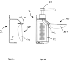
- drip tray 100 is attached to an alternative container fastening device 2.
- the container fastening device 2 comprises, like the container fastening device 1, Figure 1 a round rod 11, so that the drip tray 100 can perform a rotating or pivoting movement on the round rod 11 by means of its hinge element 103 when a liquid container 90 (with attached dosing pump 80) is inserted into the receiving area 5.
- the container fastening device 2 can be used as a stand-alone device or mounted on a wall (in Figure 4 not shown) to be available to the user near the point of care.
Landscapes
- Health & Medical Sciences (AREA)
- Public Health (AREA)
- Infusion, Injection, And Reservoir Apparatuses (AREA)
Claims (15)
- Système comprenant une coupelle d'égouttage (100) et un système de distribution de doses ou un dispositif (1, 2) de fixation de récipient,le système de distribution de doses ou le dispositif (1, 2) de fixation de récipient présentant une zone de réception (5) pour un récipient de liquide (90),la coupelle d'égouttage (100) présentant une zone (101) en forme de coupelle qui est conçue de façon à recueillir les liquides qui s'égouttent,la coupelle d'égouttage (100) comprenant un élément charnière (103) présent sur le bord de la zone (101) en forme de coupelle et un élément levier (102) relié de manière fixe à la zone (101) en forme de coupelle,et l'élément charnière (103) étant conçu de façon à fixer de manière mobile la coupelle d'égouttage (100) au distributeur de doses ou au dispositif (1, 2) de fixation de récipient, de sorte que la zone (101) en forme de coupelle soit apte à être déplacée par rapport au plan (e) de la zone (101) en forme de coupelle entre une position sensiblement verticale et une position sensiblement horizontale,l'élément levier (102) étant conçu pour faire saillie dans la zone de réception (5) en l'absence du récipient de liquide (90), tandis qu'il est positionné à l'extérieur de la zone de réception (5) lorsque le récipient de liquide (90) est inséré dans la zone de réception (5),la zone (101) en forme de coupelle, lorsque le réservoir de liquide (90) est inséré dans la zone de réception (5), étant maintenue dans une position sensiblement horizontale au moyen de l'élément levier (102), tandis qu'en l'absence du réservoir de liquide (90), la zone (101) en forme de coupelle est suspendue à l'élément charnière (103) dans une position sensiblement verticale.
- Système selon la revendication 1, dans lequel l'élément levier (102) est conçu de telle sorte que, suite à l'insertion du réservoir de liquide (90) dans la zone de réception (5), l'élément levier (102) soit déplacé hors de la zone de réception (5), ce qui permet de déplacer la zone (101) en forme de coupelle au moyen de l'élément levier (102) de la position sensiblement verticale à une position sensiblement horizontale.
- Système selon la revendication 1 ou la revendication 2,
dans lequel la zone (101) en forme de coupelle et l'élément levier (102) sont formés d'une seule pièce de matériau ou dans lequel la zone en forme de coupelle, l'élément levier (102) et l'élément charnière (103) sont formés d'une seule pièce de matériau. - Système selon la revendication 3, dans lequel la coupelle d'égouttage (100) est fabriquée à partir d'une seule pièce moulée par injection.
- Système selon une ou plusieurs des revendications précédentes, dans lequel la zone (101) en forme de coupelle présente une capacité allant de 20ml à 200ml et/ou une hauteur H allant de 1 à 4cm, de préférence de 1,5cm à 2,5cm.
- Système selon une ou plusieurs des revendications précédentes,
dans lequel l'élément charnière (103) est apte à être relié de manière inamovible, ou de préférence de manière amovible, au système de distribution de doses ou au dispositif (1, 2) de fixation de récipient. - Système selon une ou plusieurs des revendications précédentes, dans lequel l'élément charnière (103) est apte à être relié de manière inamovible ou de préférence amovible à un élément en forme de tige présent sur le système de distribution de doses ou sur le dispositif (1, 2) de fixation de récipient et disposé horizontalement.
- Système selon la revendication 7, dans lequel l'élément charnière (103) est configuré sous la forme d'une partie élastique de charnière (103) qui est apte à entourer au moins partiellement l'élément en forme de tige (11).
- Système selon la revendication 8, dans lequel la partie élastique de charnière (103) est formée par une partie de l'élément levier (102), en ce que l'élément levier (102) forme, dans la zone de sa transition avec la zone (101) en forme de coupelle, une rainure continue et de forme cylindrique, qui est apte à entourer au moins partiellement l'élément en forme de tige (11).
- Système selon la revendication 9, dans lequel la partie élastique de charnière (103) entoure l'élément en forme de tige (11) sur 51 % à 95 % de sa circonférence.
- Système selon une ou plusieurs des revendications précédentes,
dans lequel l'élément levier (102) est coudé par rapport au plan (e) de la zone (101) en forme de coupelle, selon un angle α allant de 80° à 100°, de préférence de 85° à 95°. - Système selon une ou plusieurs des revendications précédentes, dans lequel l'élément levier (102) présente un rapport de sa longueur L par rapport à une profondeur T de la zone (101) en forme de coupelle allant de 0,2 à 0,6, la profondeur T désignant une extension de la zone (101) en forme de coupelle allant en s'éloignant du système de distribution de doses ou du dispositif (1, 2) de fixation de récipient.
- Système selon une ou plusieurs des revendications précédentes, le système comprenant un système de distribution de doses et un récipient de liquide (90) rempli d'un liquide de nettoyage, d'un liquide de désinfection ou d'un liquide d'entretien.
- Système selon l'une ou plusieurs des revendications précédentes 1 à 12, dans lequel le système comprend un dispositif (1, 2) de fixation de récipient et un réservoir de liquide (90) muni d'une pompe de dosage (80) et rempli d'un liquide de nettoyage, d'un liquide de désinfection ou d'un liquide de soin.
- Système selon la revendication 14, dans lequel le dispositif (1, 2) de fixation du récipient comprend :- un support (4, 41) comportant une zone de réception (5) pour le récipient de liquide (90), le support (4, 41) comportant une première zone de fixation (51), une deuxième zone de fixation (52) et une troisième zone de fixation (53), les première (51), deuxième (52) et troisième (53) zones de fixation comprenant des tiges,- et un moyen de fixation (7) pour fixer de manière amovible le support (4, 41) à des objets, le moyen de fixation (7) étant apte à être fixé à la première zone de fixation (51), et le moyen de fixation (7) étant apte à prendre ainsi une première position de maintien, et le moyen de fixation (7) étant apte à être fixé à la deuxième zone de fixation (52), et le moyen de fixation (7) étant apte à ainsi prendre une deuxième position de maintien, et le moyen de fixation (7) étant apte à être fixé à la troisième zone de fixation (53), et le moyen de fixation (7) étant apte à prendre ainsi une troisième position de maintien,les tiges de la troisième (53) zone de fixation (54) s'étendant en biais par rapport aux tiges de la première zone de fixation (51), en particulier selon un angle allant de 10° à 80°, notamment de 20° à 60°, en particulier de 30 à 50°,la première position de maintien permettant la fixation du support (4, 41) à un objet orienté horizontalement et la deuxième position de maintien permettant la fixation du support (4, 41) à un objet orienté verticalement, et la troisième position de maintien permettant la fixation du support (4, 41) à un objet orienté obliquement.
Applications Claiming Priority (2)
| Application Number | Priority Date | Filing Date | Title |
|---|---|---|---|
| DE102019117450.3A DE102019117450A1 (de) | 2019-06-28 | 2019-06-28 | Tropfschale zum Anbringen an einem Dosierspendersystem oder an einer Behälterbefestigungsvorrichtung |
| PCT/EP2020/067080 WO2020260148A1 (fr) | 2019-06-28 | 2020-06-19 | Bac d'égouttage pour l'application sur un système de distribution de doses ou sur un dispositif de fixation de récipient |
Publications (2)
| Publication Number | Publication Date |
|---|---|
| EP3930552A1 EP3930552A1 (fr) | 2022-01-05 |
| EP3930552B1 true EP3930552B1 (fr) | 2024-08-28 |
Family
ID=71138724
Family Applications (1)
| Application Number | Title | Priority Date | Filing Date |
|---|---|---|---|
| EP20734491.2A Active EP3930552B1 (fr) | 2019-06-28 | 2020-06-19 | Bac d'égouttage pour l'application sur un système de distribution de doses ou sur un dispositif de fixation de récipient |
Country Status (3)
| Country | Link |
|---|---|
| EP (1) | EP3930552B1 (fr) |
| DE (1) | DE102019117450A1 (fr) |
| WO (1) | WO2020260148A1 (fr) |
Families Citing this family (1)
| Publication number | Priority date | Publication date | Assignee | Title |
|---|---|---|---|---|
| US20240188763A1 (en) * | 2021-04-21 | 2024-06-13 | ADA Cosmetics International GmbH | Wall-mounted dispenser |
Family Cites Families (8)
| Publication number | Priority date | Publication date | Assignee | Title |
|---|---|---|---|---|
| US8353427B2 (en) * | 2010-10-11 | 2013-01-15 | Konrad Landauer | Automatic dispenser for hand-sanitizer lotion |
| BR112014010694B1 (pt) * | 2011-11-04 | 2020-11-10 | Op-Hygiene Ip Gmbh | método de monitoramento de contaminante para dispensador |
| DE202015103187U1 (de) * | 2015-06-17 | 2016-06-20 | Schülke & Mayr GmbH | Spendersystem |
| DE102015120279A1 (de) * | 2015-11-24 | 2017-05-24 | Bode Chemie Gmbh | Behälterbefestigungssystem |
| DE102016119609A1 (de) * | 2016-10-14 | 2018-04-19 | Bode Chemie Gmbh | Behälteraufnahmevorrichtung für einen Abgabebehälter |
| US10182685B2 (en) * | 2016-11-11 | 2019-01-22 | Op-Hygiene Ip Gmbh | Cover lift mechanism for fluid dispenser |
| WO2018102164A1 (fr) * | 2016-11-29 | 2018-06-07 | Gojo Industries, Inc. | Distributeurs actionnés manuellement pour bouteilles compressibles |
| DE202018003655U1 (de) * | 2017-08-09 | 2018-10-29 | Matthias Fisser | Leicht handhabbare Vorrichtung als Desinfektionslösungsspender zur erleichterten Desinfektion und haltesicheren Anbringung an Bettgestellen |
-
2019
- 2019-06-28 DE DE102019117450.3A patent/DE102019117450A1/de active Pending
-
2020
- 2020-06-19 EP EP20734491.2A patent/EP3930552B1/fr active Active
- 2020-06-19 WO PCT/EP2020/067080 patent/WO2020260148A1/fr not_active Ceased
Also Published As
| Publication number | Publication date |
|---|---|
| DE102019117450A1 (de) | 2020-12-31 |
| WO2020260148A1 (fr) | 2020-12-30 |
| EP3930552A1 (fr) | 2022-01-05 |
Similar Documents
| Publication | Publication Date | Title |
|---|---|---|
| DE102015109681A1 (de) | Spendersystem | |
| DE202015103187U1 (de) | Spendersystem | |
| DE4016353A1 (de) | Vorrichtung zum auftragen von streichfaehigen, insbesondere medizinischen behandlungsstoffen auf menschliche oder tierische koerperteile | |
| EP3629864B1 (fr) | Système de retenue prévu pour fournir un emballage muni de lingettes de nettoyage ou de désinfection ou de gants jetables | |
| EP3930552B1 (fr) | Bac d'égouttage pour l'application sur un système de distribution de doses ou sur un dispositif de fixation de récipient | |
| EP3379987B1 (fr) | Système de fixation de récipient | |
| DE8512617U1 (de) | Absaugvorrichtung, insbesondere zur Verwendung bei der medizinischen Fußpflege | |
| DE102005047188B4 (de) | Chirurgische Halterung, dazugehörigen Satz und chirurgischer Behälter mit einer solchen Halterung | |
| DE102021131862B4 (de) | Halterung für Hygieneprodukte in der Dusche | |
| DE102006038273B4 (de) | Vorrichtung zum Fangen von Insekten | |
| DE202006018494U1 (de) | Strumpfausziehhilfsmittel | |
| DE2243761A1 (de) | Halter mit abreissvorrichtung fuer bahnfoermiges material | |
| DE69514452T2 (de) | Wegwerfbare Absaugvorrichtung für Speichel | |
| DE29603305U1 (de) | Haltevorrichtung für die Wandhalterung von Küchenutensilien | |
| DE20211602U1 (de) | Vorrichtung zur Abgabe von Putztüchern | |
| DE102015016405B4 (de) | Haltevorrichtung für zahnärztliche Übertragungsinstrumente | |
| DE3231274C2 (de) | Muskelkraftbetriebenes Wasch- und Massagegerät | |
| EP1023878A2 (fr) | Support comportant une pince | |
| DE202021106601U1 (de) | Halterung für Hygieneprodukte in der Dusche | |
| DE9012620U1 (de) | Flüssigkeitsaufnehmer | |
| DE819452C (de) | Fussraste in Verbindung mit einem Friseurwaschtisch o. dgl. | |
| DE202020102559U1 (de) | Desinfektionsmittelspender zur berührungslosen Ausgabe von Desinfektionsmittel | |
| EP3530164A1 (fr) | Baignoires d'accouchement | |
| DE202019101894U1 (de) | Vorrichtung zum Anbringen eines Gegenstandes an einem Patientenbett | |
| DE202019101893U1 (de) | Vorrichtung zum Anbringen eines Gegenstandes an einem Patientenbett |
Legal Events
| Date | Code | Title | Description |
|---|---|---|---|
| STAA | Information on the status of an ep patent application or granted ep patent |
Free format text: STATUS: UNKNOWN |
|
| STAA | Information on the status of an ep patent application or granted ep patent |
Free format text: STATUS: THE INTERNATIONAL PUBLICATION HAS BEEN MADE |
|
| PUAI | Public reference made under article 153(3) epc to a published international application that has entered the european phase |
Free format text: ORIGINAL CODE: 0009012 |
|
| STAA | Information on the status of an ep patent application or granted ep patent |
Free format text: STATUS: REQUEST FOR EXAMINATION WAS MADE |
|
| 17P | Request for examination filed |
Effective date: 20210928 |
|
| AK | Designated contracting states |
Kind code of ref document: A1 Designated state(s): AL AT BE BG CH CY CZ DE DK EE ES FI FR GB GR HR HU IE IS IT LI LT LU LV MC MK MT NL NO PL PT RO RS SE SI SK SM TR |
|
| DAV | Request for validation of the european patent (deleted) | ||
| DAX | Request for extension of the european patent (deleted) | ||
| GRAP | Despatch of communication of intention to grant a patent |
Free format text: ORIGINAL CODE: EPIDOSNIGR1 |
|
| STAA | Information on the status of an ep patent application or granted ep patent |
Free format text: STATUS: GRANT OF PATENT IS INTENDED |
|
| INTG | Intention to grant announced |
Effective date: 20240408 |
|
| GRAS | Grant fee paid |
Free format text: ORIGINAL CODE: EPIDOSNIGR3 |
|
| GRAA | (expected) grant |
Free format text: ORIGINAL CODE: 0009210 |
|
| STAA | Information on the status of an ep patent application or granted ep patent |
Free format text: STATUS: THE PATENT HAS BEEN GRANTED |
|
| AK | Designated contracting states |
Kind code of ref document: B1 Designated state(s): AL AT BE BG CH CY CZ DE DK EE ES FI FR GB GR HR HU IE IS IT LI LT LU LV MC MK MT NL NO PL PT RO RS SE SI SK SM TR |
|
| P01 | Opt-out of the competence of the unified patent court (upc) registered |
Free format text: CASE NUMBER: APP_39543/2024 Effective date: 20240724 |
|
| REG | Reference to a national code |
Ref country code: CH Ref legal event code: EP |
|
| REG | Reference to a national code |
Ref country code: DE Ref legal event code: R096 Ref document number: 502020009032 Country of ref document: DE |
|
| REG | Reference to a national code |
Ref country code: IE Ref legal event code: FG4D Free format text: LANGUAGE OF EP DOCUMENT: GERMAN |
|
| REG | Reference to a national code |
Ref country code: LT Ref legal event code: MG9D |
|
| PG25 | Lapsed in a contracting state [announced via postgrant information from national office to epo] |
Ref country code: NO Free format text: LAPSE BECAUSE OF FAILURE TO SUBMIT A TRANSLATION OF THE DESCRIPTION OR TO PAY THE FEE WITHIN THE PRESCRIBED TIME-LIMIT Effective date: 20241128 |
|
| PG25 | Lapsed in a contracting state [announced via postgrant information from national office to epo] |
Ref country code: NL Free format text: LAPSE BECAUSE OF FAILURE TO SUBMIT A TRANSLATION OF THE DESCRIPTION OR TO PAY THE FEE WITHIN THE PRESCRIBED TIME-LIMIT Effective date: 20240828 Ref country code: PT Free format text: LAPSE BECAUSE OF FAILURE TO SUBMIT A TRANSLATION OF THE DESCRIPTION OR TO PAY THE FEE WITHIN THE PRESCRIBED TIME-LIMIT Effective date: 20241230 Ref country code: PL Free format text: LAPSE BECAUSE OF FAILURE TO SUBMIT A TRANSLATION OF THE DESCRIPTION OR TO PAY THE FEE WITHIN THE PRESCRIBED TIME-LIMIT Effective date: 20240828 Ref country code: GR Free format text: LAPSE BECAUSE OF FAILURE TO SUBMIT A TRANSLATION OF THE DESCRIPTION OR TO PAY THE FEE WITHIN THE PRESCRIBED TIME-LIMIT Effective date: 20241129 Ref country code: FI Free format text: LAPSE BECAUSE OF FAILURE TO SUBMIT A TRANSLATION OF THE DESCRIPTION OR TO PAY THE FEE WITHIN THE PRESCRIBED TIME-LIMIT Effective date: 20240828 |
|
| PG25 | Lapsed in a contracting state [announced via postgrant information from national office to epo] |
Ref country code: BG Free format text: LAPSE BECAUSE OF FAILURE TO SUBMIT A TRANSLATION OF THE DESCRIPTION OR TO PAY THE FEE WITHIN THE PRESCRIBED TIME-LIMIT Effective date: 20240828 |
|
| PG25 | Lapsed in a contracting state [announced via postgrant information from national office to epo] |
Ref country code: LV Free format text: LAPSE BECAUSE OF FAILURE TO SUBMIT A TRANSLATION OF THE DESCRIPTION OR TO PAY THE FEE WITHIN THE PRESCRIBED TIME-LIMIT Effective date: 20240828 |
|
| REG | Reference to a national code |
Ref country code: NL Ref legal event code: MP Effective date: 20240828 |
|
| PG25 | Lapsed in a contracting state [announced via postgrant information from national office to epo] |
Ref country code: IS Free format text: LAPSE BECAUSE OF FAILURE TO SUBMIT A TRANSLATION OF THE DESCRIPTION OR TO PAY THE FEE WITHIN THE PRESCRIBED TIME-LIMIT Effective date: 20241228 |
|
| PG25 | Lapsed in a contracting state [announced via postgrant information from national office to epo] |
Ref country code: HR Free format text: LAPSE BECAUSE OF FAILURE TO SUBMIT A TRANSLATION OF THE DESCRIPTION OR TO PAY THE FEE WITHIN THE PRESCRIBED TIME-LIMIT Effective date: 20240828 |
|
| PG25 | Lapsed in a contracting state [announced via postgrant information from national office to epo] |
Ref country code: RS Free format text: LAPSE BECAUSE OF FAILURE TO SUBMIT A TRANSLATION OF THE DESCRIPTION OR TO PAY THE FEE WITHIN THE PRESCRIBED TIME-LIMIT Effective date: 20241128 Ref country code: ES Free format text: LAPSE BECAUSE OF FAILURE TO SUBMIT A TRANSLATION OF THE DESCRIPTION OR TO PAY THE FEE WITHIN THE PRESCRIBED TIME-LIMIT Effective date: 20240828 |
|
| PG25 | Lapsed in a contracting state [announced via postgrant information from national office to epo] |
Ref country code: RS Free format text: LAPSE BECAUSE OF FAILURE TO SUBMIT A TRANSLATION OF THE DESCRIPTION OR TO PAY THE FEE WITHIN THE PRESCRIBED TIME-LIMIT Effective date: 20241128 Ref country code: PT Free format text: LAPSE BECAUSE OF FAILURE TO SUBMIT A TRANSLATION OF THE DESCRIPTION OR TO PAY THE FEE WITHIN THE PRESCRIBED TIME-LIMIT Effective date: 20241230 Ref country code: PL Free format text: LAPSE BECAUSE OF FAILURE TO SUBMIT A TRANSLATION OF THE DESCRIPTION OR TO PAY THE FEE WITHIN THE PRESCRIBED TIME-LIMIT Effective date: 20240828 Ref country code: NO Free format text: LAPSE BECAUSE OF FAILURE TO SUBMIT A TRANSLATION OF THE DESCRIPTION OR TO PAY THE FEE WITHIN THE PRESCRIBED TIME-LIMIT Effective date: 20241128 Ref country code: NL Free format text: LAPSE BECAUSE OF FAILURE TO SUBMIT A TRANSLATION OF THE DESCRIPTION OR TO PAY THE FEE WITHIN THE PRESCRIBED TIME-LIMIT Effective date: 20240828 Ref country code: LV Free format text: LAPSE BECAUSE OF FAILURE TO SUBMIT A TRANSLATION OF THE DESCRIPTION OR TO PAY THE FEE WITHIN THE PRESCRIBED TIME-LIMIT Effective date: 20240828 Ref country code: IS Free format text: LAPSE BECAUSE OF FAILURE TO SUBMIT A TRANSLATION OF THE DESCRIPTION OR TO PAY THE FEE WITHIN THE PRESCRIBED TIME-LIMIT Effective date: 20241228 Ref country code: HR Free format text: LAPSE BECAUSE OF FAILURE TO SUBMIT A TRANSLATION OF THE DESCRIPTION OR TO PAY THE FEE WITHIN THE PRESCRIBED TIME-LIMIT Effective date: 20240828 Ref country code: GR Free format text: LAPSE BECAUSE OF FAILURE TO SUBMIT A TRANSLATION OF THE DESCRIPTION OR TO PAY THE FEE WITHIN THE PRESCRIBED TIME-LIMIT Effective date: 20241129 Ref country code: FI Free format text: LAPSE BECAUSE OF FAILURE TO SUBMIT A TRANSLATION OF THE DESCRIPTION OR TO PAY THE FEE WITHIN THE PRESCRIBED TIME-LIMIT Effective date: 20240828 Ref country code: ES Free format text: LAPSE BECAUSE OF FAILURE TO SUBMIT A TRANSLATION OF THE DESCRIPTION OR TO PAY THE FEE WITHIN THE PRESCRIBED TIME-LIMIT Effective date: 20240828 Ref country code: BG Free format text: LAPSE BECAUSE OF FAILURE TO SUBMIT A TRANSLATION OF THE DESCRIPTION OR TO PAY THE FEE WITHIN THE PRESCRIBED TIME-LIMIT Effective date: 20240828 |
|
| PG25 | Lapsed in a contracting state [announced via postgrant information from national office to epo] |
Ref country code: RO Free format text: LAPSE BECAUSE OF FAILURE TO SUBMIT A TRANSLATION OF THE DESCRIPTION OR TO PAY THE FEE WITHIN THE PRESCRIBED TIME-LIMIT Effective date: 20240828 Ref country code: SM Free format text: LAPSE BECAUSE OF FAILURE TO SUBMIT A TRANSLATION OF THE DESCRIPTION OR TO PAY THE FEE WITHIN THE PRESCRIBED TIME-LIMIT Effective date: 20240828 Ref country code: DK Free format text: LAPSE BECAUSE OF FAILURE TO SUBMIT A TRANSLATION OF THE DESCRIPTION OR TO PAY THE FEE WITHIN THE PRESCRIBED TIME-LIMIT Effective date: 20240828 |
|
| PG25 | Lapsed in a contracting state [announced via postgrant information from national office to epo] |
Ref country code: EE Free format text: LAPSE BECAUSE OF FAILURE TO SUBMIT A TRANSLATION OF THE DESCRIPTION OR TO PAY THE FEE WITHIN THE PRESCRIBED TIME-LIMIT Effective date: 20240828 |
|
| PG25 | Lapsed in a contracting state [announced via postgrant information from national office to epo] |
Ref country code: CZ Free format text: LAPSE BECAUSE OF FAILURE TO SUBMIT A TRANSLATION OF THE DESCRIPTION OR TO PAY THE FEE WITHIN THE PRESCRIBED TIME-LIMIT Effective date: 20240828 |
|
| PG25 | Lapsed in a contracting state [announced via postgrant information from national office to epo] |
Ref country code: SK Free format text: LAPSE BECAUSE OF FAILURE TO SUBMIT A TRANSLATION OF THE DESCRIPTION OR TO PAY THE FEE WITHIN THE PRESCRIBED TIME-LIMIT Effective date: 20240828 Ref country code: IT Free format text: LAPSE BECAUSE OF FAILURE TO SUBMIT A TRANSLATION OF THE DESCRIPTION OR TO PAY THE FEE WITHIN THE PRESCRIBED TIME-LIMIT Effective date: 20240828 |
|
| REG | Reference to a national code |
Ref country code: DE Ref legal event code: R097 Ref document number: 502020009032 Country of ref document: DE |
|
| PLBE | No opposition filed within time limit |
Free format text: ORIGINAL CODE: 0009261 |
|
| STAA | Information on the status of an ep patent application or granted ep patent |
Free format text: STATUS: NO OPPOSITION FILED WITHIN TIME LIMIT |
|
| PGFP | Annual fee paid to national office [announced via postgrant information from national office to epo] |
Ref country code: DE Payment date: 20250618 Year of fee payment: 6 |
|
| 26N | No opposition filed |
Effective date: 20250530 |
|
| PG25 | Lapsed in a contracting state [announced via postgrant information from national office to epo] |
Ref country code: SE Free format text: LAPSE BECAUSE OF FAILURE TO SUBMIT A TRANSLATION OF THE DESCRIPTION OR TO PAY THE FEE WITHIN THE PRESCRIBED TIME-LIMIT Effective date: 20240828 |
|
| REG | Reference to a national code |
Ref country code: CH Ref legal event code: H13 Free format text: ST27 STATUS EVENT CODE: U-0-0-H10-H13 (AS PROVIDED BY THE NATIONAL OFFICE) Effective date: 20260127 |
|
| PG25 | Lapsed in a contracting state [announced via postgrant information from national office to epo] |
Ref country code: MC Free format text: LAPSE BECAUSE OF FAILURE TO SUBMIT A TRANSLATION OF THE DESCRIPTION OR TO PAY THE FEE WITHIN THE PRESCRIBED TIME-LIMIT Effective date: 20240828 |
|
| PG25 | Lapsed in a contracting state [announced via postgrant information from national office to epo] |
Ref country code: LU Free format text: LAPSE BECAUSE OF NON-PAYMENT OF DUE FEES Effective date: 20250619 |
|
| GBPC | Gb: european patent ceased through non-payment of renewal fee |
Effective date: 20250619 |
|
| REG | Reference to a national code |
Ref country code: BE Ref legal event code: MM Effective date: 20250630 |
|
| PG25 | Lapsed in a contracting state [announced via postgrant information from national office to epo] |
Ref country code: GB Free format text: LAPSE BECAUSE OF NON-PAYMENT OF DUE FEES Effective date: 20250619 |
|
| PG25 | Lapsed in a contracting state [announced via postgrant information from national office to epo] |
Ref country code: IE Free format text: LAPSE BECAUSE OF NON-PAYMENT OF DUE FEES Effective date: 20250619 |
|
| PG25 | Lapsed in a contracting state [announced via postgrant information from national office to epo] |
Ref country code: BE Free format text: LAPSE BECAUSE OF NON-PAYMENT OF DUE FEES Effective date: 20250630 |
|
| PG25 | Lapsed in a contracting state [announced via postgrant information from national office to epo] |
Ref country code: FR Free format text: LAPSE BECAUSE OF NON-PAYMENT OF DUE FEES Effective date: 20250630 |
|
| PG25 | Lapsed in a contracting state [announced via postgrant information from national office to epo] |
Ref country code: CH Free format text: LAPSE BECAUSE OF NON-PAYMENT OF DUE FEES Effective date: 20250630 |