EP3930552B1 - Drip tray for attaching to a dispenser system, or to a container fixation device - Google Patents
Drip tray for attaching to a dispenser system, or to a container fixation device Download PDFInfo
- Publication number
- EP3930552B1 EP3930552B1 EP20734491.2A EP20734491A EP3930552B1 EP 3930552 B1 EP3930552 B1 EP 3930552B1 EP 20734491 A EP20734491 A EP 20734491A EP 3930552 B1 EP3930552 B1 EP 3930552B1
- Authority
- EP
- European Patent Office
- Prior art keywords
- region
- fastening
- container
- shell
- lever element
- Prior art date
- Legal status (The legal status is an assumption and is not a legal conclusion. Google has not performed a legal analysis and makes no representation as to the accuracy of the status listed.)
- Active
Links
Images


Classifications
-
- A—HUMAN NECESSITIES
- A47—FURNITURE; DOMESTIC ARTICLES OR APPLIANCES; COFFEE MILLS; SPICE MILLS; SUCTION CLEANERS IN GENERAL
- A47K—SANITARY EQUIPMENT; ACCESSORIES THEREFOR, e.g. TOILET ACCESSORIES
- A47K5/00—Holders or dispensers for soap, toothpaste or the like
- A47K5/06—Dispensers for soap
- A47K5/12—Dispensers for soap for liquid or pasty soap
- A47K5/1201—Dispensers for soap for liquid or pasty soap hand-carried
-
- A—HUMAN NECESSITIES
- A47—FURNITURE; DOMESTIC ARTICLES OR APPLIANCES; COFFEE MILLS; SPICE MILLS; SUCTION CLEANERS IN GENERAL
- A47K—SANITARY EQUIPMENT; ACCESSORIES THEREFOR, e.g. TOILET ACCESSORIES
- A47K2201/00—Details of connections of bathroom accessories, e.g. fixing soap or towel holder to a wall
- A47K2201/02—Connections to a wall mounted support
-
- A—HUMAN NECESSITIES
- A47—FURNITURE; DOMESTIC ARTICLES OR APPLIANCES; COFFEE MILLS; SPICE MILLS; SUCTION CLEANERS IN GENERAL
- A47K—SANITARY EQUIPMENT; ACCESSORIES THEREFOR, e.g. TOILET ACCESSORIES
- A47K5/00—Holders or dispensers for soap, toothpaste or the like
- A47K5/06—Dispensers for soap
- A47K5/12—Dispensers for soap for liquid or pasty soap
- A47K5/1202—Dispensers for soap for liquid or pasty soap dispensing dosed volume
- A47K5/1204—Dispensers for soap for liquid or pasty soap dispensing dosed volume by means of a rigid dispensing chamber and pistons
- A47K5/1205—Dispensing from the top of the dispenser with a vertical piston
Definitions
- the present invention relates to a system comprising a drip tray and a dosing dispenser system or a container fastening device.
- Dispensing devices Cleaning fluids, disinfection fluids or care fluids are usually made available to the user in suitable dispensing devices.
- dispensing devices for example “dispenser”, “dispensing unit” and a variety of other terms.
- the dosing pump is connected to a holder (e.g. table stand or wall bracket).
- a container that is intended for single use only for hygiene reasons is usually replaced by inserting it into a receiving area of the device.
- dosing dispenser systems that are operated manually as well as devices in which the dosing pump is electrically driven.
- the term "container fastening device” in the following refers to a holding device into which a dosing dispenser consisting of a container and attached dosing pump can be inserted.
- a dosing pump that is already mounted on the filled container by the manufacturer and is intended as a disposable item avoids the need to clean the dosing pump, in contrast to the dosing dispenser system mentioned above.
- the holding device is intended, for example, for fastening to the wall or for clamping to objects.
- the container part of the dosing dispenser is inserted into the receiving area of the device.
- dispensers Dosing dispensing systems and “container fastening devices” within the meaning of the definitions used here are also referred to collectively as “dispensers” hereinafter.
- the US 2018/146828 A1 refers to a dispenser for liquids with a replaceable container and a drip tray.
- the drip tray is integrated into the base plate of the dispenser.
- Drip trays that protrude from the dispenser and extend into the room can be a source of danger, as they can be overlooked by nursing staff and especially by patients with impaired vision.
- the risk of getting caught on the drip tray that extends away from the dispenser is particularly high if no container or dosing pump is used, as the drip tray that extends into the room can then be overlooked even more easily.
- the object of the present invention is therefore to improve the handling of known dispensers, in particular container fastening systems.
- a system with a drip tray and a dosing dispenser system or a container fastening device is proposed.
- the drip tray has a bowl-shaped area which is designed to catch dripping liquids.
- the drip tray also comprises a hinge element and a lever element, wherein the lever element is angled relative to the plane of the bowl-shaped area.
- the bowl-shaped area is movably attached to the dosing dispenser or to the container fastening device by means of the hinge element.
- the bowl-shaped area is moved between a (hanging) vertical position and a horizontal position in relation to the plane of the bowl-shaped area.
- the lever element is designed and shaped in such a way that it protrudes into the receiving area in the absence of the liquid container and protrudes from this when the liquid container is inserted into the receiving area. is displaced so that when the liquid container is inserted into the receiving area, the bowl-shaped area is moved from a vertical position to a horizontal position.
- the drip tray according to the invention is thus in a horizontal "use” arrangement when a liquid container is in the dispenser and folds downwards when the container is removed. When the dispenser is not equipped with the liquid container, the drip tray does not protrude into the room, so that the risk for staff or patients of accidentally getting caught on the drip tray is significantly reduced.
- the drip tray comprises a bowl-shaped area which can catch dripping liquid so that it does not drip onto the floor.
- the bowl-shaped area should be dimensioned so that dripping liquid is safely caught. Any basic shape is possible, for example square or rounded.
- the bowl-shaped area has a depth T and width B in the range of 5 cm to 12 cm each.
- the height H is often between 1 cm and 4 cm, preferably 1.5 cm to 2.5 cm.
- the capacity of the bowl-shaped area is normally 20 ml to 200 ml.
- the bowl-shaped area is normally made of metal or plastic.
- the weight of the bowl-shaped area is typically 20 g to 60 g.
- the bowl-shaped area, the hinge element and the lever element can consist of separate components.
- the bowl-shaped area and the lever element are formed from a single piece of material (i.e. in one piece).
- the bowl-shaped area, the lever element and the hinge element are formed in one piece. Accordingly, a drip tray according to this particularly preferred embodiment can be produced practically and inexpensively from a single injection-molded part.
- the lever element is dimensioned in such a way that it extends into the receiving area of the dispenser in the absence of a liquid container, and is then pushed away to the side when the liquid container is inserted into the receiving area.
- the sideways movement of the lever element triggered by the pushing away simultaneously rotates the bowl-shaped area connected to the lever element from its vertical position by 90° into a horizontal orientation.
- the lever element must be connected to the bowl-shaped area at an approximately vertical angle, i.e. there must be an angle (in the hereinafter referred to as " ⁇ ") of 80° to 100°, in particular 85° to 95°, particularly preferably 90°.
- the lever element preferably has a ratio of its length L to a depth T of the bowl-shaped region of 0.20 to 0.6, with the depth T designating an extension of the bowl-shaped region pointing away from the hinge element.
- the bowl-shaped region can have a dimension (depth T x width B) of 10 cm x 12 cm and the lever element a length L of 4 cm. This results in a ratio L to T of 0.4.
- the hinge element is a component on the drip tray which, in conjunction with a component of the dispenser that is coordinated with it, creates a joint that can rotate around an axis.
- the hinge element is anchored to a rod with a round cross-section that is attached horizontally to the dispenser and then forms the axis of rotation.
- the hinge element partially or completely surrounds the rod.
- the dispenser can have pins that interact with the hinge element, for example.
- the hinge element and thus the drip tray can already be permanently connected to the dosing dispenser system or the container fastening device by the manufacturer.
- a detachable connection between the drip tray and the dispenser is provided.
- a detachable arrangement makes it easier to clean the drip tray.
- the hinge element as a "hinge tab" which partially surrounds the rod-shaped element, preferably by more than 50%, in particular 51% to 95%, particularly preferably 65% to 80% of its circumference.
- a hinge tab refers to an element which comprises one or more protruding, cylindrically curved shaped elements (tabs) which can surround the rod-shaped element and thus allow the drip tray to be attached to the dispenser in a movable manner.
- the attachment should be designed in such a way that the drip tray is held securely on the dispenser, but can only be pulled off the rod with a certain amount of force.
- the elasticity of the material used for the hinge tab must be taken into account here.
- the hinge tab is formed by a portion of the lever element, i.e. the lever element forms a continuous cylindrical groove in the area of its transition to the bowl-shaped area, which can engage around a rod-shaped element on the dispenser as a hinge tab.
- This embodiment of the hinge element can be provided in particular with the one-piece design of the drip tray mentioned above.
- the hinge tab should also engage around the rod-shaped element by more than 50% in this embodiment. This can be achieved by a suitable shape of the lever element.
- the portion of the lever element designed as a hinge tab to form a groove with an exactly semicircular cross-section (i.e. engaging around the rod by 50%). In this case, additional knobs in the area of the groove can cause the rod to engage around by more than 50%.
- the system can additionally comprise a liquid container which is filled with a cleaning liquid, a disinfectant liquid or a care liquid.
- a system with a drip tray and container fastening device can additionally comprise a liquid container provided with a dosing pump, which is already filled with a cleaning liquid, a disinfectant liquid or a care liquid.
- the drip tray in the WO2017089323 It is advisable to use the container fastening devices presented here, as these can be attached to a wide range of items present at the point of care.
- Figure 1 shows an already in WO2017089323 disclosed example of an alternative container fastening device 1 to which the drip tray proposed by the present invention is attached.
- the container fastening device 1 has a holder 4 and a fastening means 7.
- the holder 4 has a receiving area 5 which is designed to receive a container (not shown).
- the holder 4 is formed from several sections of a single continuous round rod 6 which is bent in sections and forms the receiving area 5.
- the round rod 6 is made of stainless steel and has a diameter of 4.0 mm.
- the receiving area 5 comprises a base 8, a rear part 9 and a front part 10.
- the front part 10 has a pair of round rods 19 running parallel in the longitudinal direction LR of the holder 4 to form front support elements 55 with a length of 80 mm, which are spaced apart by 80 mm.
- these round rods 19 are connected via a bend oriented essentially transversely to the longitudinal direction LR.
- the bend is also formed by a round rod 11.
- the round rod 11 is suitable for fastening the drip tray according to the invention.
- the base 8 has a pair of round bars with a length of 20 mm that run transversely (90°) to the longitudinal direction LR and parallel to one another and that run in a first plane.
- the round bars 20 of the first section of the base 8 merge into two round bars 21 of a length of 25 mm which bend outwards by 45° and whose distance from one another increases steadily with distance from the first section of the base 8, wherein the round bars 21 of the second section of the base 8 also run in the first plane, in order finally to merge in a short arc into the round bars 19 of the front part 10 which run essentially in the longitudinal direction LR of the holder 4.
- another pair of parallel round bars 23 is arranged at an angle of 45° to the round bars 20 of the first section of the base 8 and running in a third plane, such that this additional pair of parallel round bars 23, which have a length of 28 mm, connects the round bars 20 of the first section of the base 8 with those of the first section of the rear part, the respective round bars thus extend each one merges into the other in a short arc.
- the round bars 22 of the first section of the back part 9 merge via a short bend into a pair of parallel round bars 54 of the second section of the back part 9.
- the round bars 54 of the second section of the back part 9 are inclined, in this case at an angle of 45° to the round bars 22 of the first section of the back part 9, and are arranged inwards and thus running in a fourth plane.
- these round bars of the second section of the back part 9 merge into round bars 25 of the end section of the back part 9.
- the round bars 25 of the end section of the back part 9 are arranged perpendicularly, i.e.
- the fastening means 7 shown has a clamping device 12, by means of which the holder 4 can be fastened to the objects.
- the clamping device 12 has a first clamping jaw 13 and a second clamping jaw 14, wherein the distance between the first clamping jaw 13 and the second clamping jaw 14 can be changed by a screw device 15, which can be operated in particular manually, in such a way that the clamping jaws can be moved towards and away from one another.
- the second clamping jaw 14 is plate-shaped, wherein the effective clamping region 140 of the second clamping jaw 14 has a bulge which is adapted to the shape of a rod- or bar-shaped object.
- the first clamping jaw 13 consists of parallel round rods.
- the two round rods are connected to one another via a tight bend to form the effective clamping region 130 of the first clamping jaw 13.
- the effective clamping area 130 of the first clamping jaw 13 is thus adapted to the shape of a plate-shaped, flat, surface-extending object.
- the clamping device 12 is designed to be able to be fastened to rod- or plate-shaped objects with a thickness of 10-50 mm.
- the two round rods are articulated to the proximal end of the second clamping jaw 14.
- the regions 130, 140 of the clamping jaws which are effective with regard to the clamping effect on an object each have a plastic coating in order to protect the surface of the object.
- the second clamping jaw 14 has a bore through which a lower section of a bolt pin 63 is passed.
- the bolt pin 63 is previously passed between the round bars of the first clamping jaw 13.
- FIGS 2 a to c show a preferred embodiment of the drip tray 100 according to the invention in different views, namely from the side ( Figure 2 a) , from above ( Figure 2 b) and perspective from above ( Figure 2 c) .
- the embodiment of the drip tray 100 shown here as an example is designed in terms of its dimensions for attachment to the Figure 1 or Figure 4
- the container fastening devices shown are provided.
- the drip tray 100 comprises a bowl-shaped area 101, which in the embodiment shown here merges into a hinge element 103.
- a lever element 102 is connected to the hinge element 103. It would also be possible to connect the lever element 102 directly to the bowl-shaped area 101.
- the axial extension of the lever element 102 is in Figure 2 designated "h”. It forms an angle ⁇ of 90° with the plane e.
- the bowl-shaped area 101 serves to collect liquid residues that have dripped off when using a dosing dispenser.
- the bowl-shaped area 101 has a height H, a width B and a depth T.
- the width of the illustrated embodiment is 12 cm, the depth 10 cm and the height 2.5 cm.
- the depth T designates an extension of the bowl-shaped region pointing away from the hinge element 103.
- the capacity of the bowl-shaped region 101, which is made of plastic, is approximately 100 ml in the embodiment shown.
- the length L of the lever element 102 is 3 cm for the drip tray 100 shown. This results in a ratio L to T of 0.3.
- the ratio L to T should be at least 0.2 to ensure sufficient stabilization of the bowl-shaped area 101 in the horizontal (with the liquid container inserted).
- the shell-shaped area, the hinge element and the lever element could be separate, interconnected components.
- Figures 2 - 4 In the particularly advantageous embodiment presented, however, the shell-shaped region, the lever element and the hinge element are formed from a single piece of material (i.e. in one piece) as an injection-molded part.
- the hinge element 103 is designed such that it can be connected to a rod-shaped element of the container fastening device 1, namely the round rod 11 (see Figure 1 ) can be detachably connected.
- the detachable connection is achieved by the hinge element 103 partially enclosing the round rod 11.
- the hinge element 103 encloses the round rod 11 by approximately 70% of its circumference.
- the drip tray 100 can be placed on the round rod 11 with little effort and is simultaneously secured against falling off the container fastening device 1. The entire drip tray 100 can then perform a rotary movement on the round rod 11 in order to be able to move from a largely vertical position (in the absence of the liquid container) to a largely horizontal position (with the liquid container inserted).
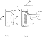
- Figures 3 a to c show the container fastening device from Figure 1 with an attached drip tray 100.
- Figure 3 a there is no container in the receiving area 5.
- the drip tray 100 then hangs in a largely vertical position with its hinge element 103 on the round rod 11.
- the lever element 102 projects into the receiving area 5 in the absence of the liquid container 90.
- Figure 3 c shows a perspective view of the ready-to-use system comprising the container fastening device 1, the drip tray 100 attached thereto and the liquid container 90 provided with a dosing pump 80.
- drip tray 100 is attached to an alternative container fastening device 2.
- the container fastening device 2 comprises, like the container fastening device 1, Figure 1 a round rod 11, so that the drip tray 100 can perform a rotating or pivoting movement on the round rod 11 by means of its hinge element 103 when a liquid container 90 (with attached dosing pump 80) is inserted into the receiving area 5.
- the container fastening device 2 can be used as a stand-alone device or mounted on a wall (in Figure 4 not shown) to be available to the user near the point of care.
Landscapes
- Health & Medical Sciences (AREA)
- Public Health (AREA)
- Infusion, Injection, And Reservoir Apparatuses (AREA)
Description
Die vorliegende Erfindung betrifft ein System aus einer Tropfschale und einem Dosierspendersystem oder einer Behälterbefestigungsvorrichtung.The present invention relates to a system comprising a drip tray and a dosing dispenser system or a container fastening device.
Die professionelle Händehygiene ist unumstritten ein Weg zur Verhinderung von Übertragungen mikrobieller Pathogene im Gesundheits- oder Pflegewesen, insbesondere in Kranken- oder Pflegeinstitutionen. Zur Händehygiene werden Reinigungsflüssigkeiten und Desinfektionsflüssigkeiten eingesetzt. Pflegeflüssigkeiten, die zur Anwendung auf der Haut vorgesehen sind, ergänzen die Hygienemaßnahmen.Professional hand hygiene is an undisputed way to prevent the transmission of microbial pathogens in the health or care sector, especially in hospitals or care institutions. Cleaning fluids and disinfectant fluids are used for hand hygiene. Care fluids intended for use on the skin complement the hygiene measures.
Reinigungsflüssigkeiten, Desinfektionsflüssigkeiten oder Pflegeflüssigkeiten werden dem Anwender üblicherweise in geeigneten Abgabevorrichtungen zur Verfügung gestellt. Bei der Beschreibung derartiger Abgabevorrichtungen wird im Stand der Technik eine uneinheitliche Terminologie verwendet, beispielsweise "Spender", "Dispensiereinheit" und eine Vielzahl weiterer Ausdrücke.Cleaning fluids, disinfection fluids or care fluids are usually made available to the user in suitable dispensing devices. In the prior art, inconsistent terminology is used to describe such dispensing devices, for example "dispenser", "dispensing unit" and a variety of other terms.
Bei den im Folgenden mit dem Ausdruck "Dosierspendersystem" bezeichneten Geräten ist die Dosierpumpe mit einer Halterung (z.B. Tischständer oder Wandhalterung) verbunden. Zum Nachfüllen des Gerätes mit der Flüssigkeit wird üblicherweise ein aus hygienischen Gründen nur zum Einmalgebrauch vorgesehener Behälter ausgetauscht, indem er in einen Aufnahmebereich des Gerätes eingesetzt wird. Es gibt Dosierspendersysteme, die manuell betätigt werden ebenso wie Geräte, bei denen die Dosierpumpe elektrisch angetrieben ist.In the devices referred to below as "dosing dispenser systems", the dosing pump is connected to a holder (e.g. table stand or wall bracket). To refill the device with liquid, a container that is intended for single use only for hygiene reasons is usually replaced by inserting it into a receiving area of the device. There are dosing dispenser systems that are operated manually as well as devices in which the dosing pump is electrically driven.
Mit dem Ausdruck "Behälterbefestigungsvorrichtung" ist im Folgenden dagegen eine Haltevorrichtung gemeint, in welche ein Dosierspender aus Behälter und aufgesetzter Dosierpumpe eingesetzt werden kann. Eine bereits herstellerseitig auf den befüllten Behälter montierte Dosierpumpe, die als Wegwerfartikel vorgesehen ist, vermeidet hierbei im Gegensatz zu dem vorstehend erwähnten Dosierspendersystem das Erfordernis die Dosierpumpe zu reinigen. Die Haltevorrichtung ist beispielsweise zum Befestigen an der Wand oder zum Anklemmen an Gegenstände vorgesehen. Der Behälteranteil des Dosierspenders wird dabei in den Aufnahmebereich der Vorrichtung eingesetzt.In contrast, the term "container fastening device" in the following refers to a holding device into which a dosing dispenser consisting of a container and attached dosing pump can be inserted. A dosing pump that is already mounted on the filled container by the manufacturer and is intended as a disposable item avoids the need to clean the dosing pump, in contrast to the dosing dispenser system mentioned above. The holding device is intended, for example, for fastening to the wall or for clamping to objects. The container part of the dosing dispenser is inserted into the receiving area of the device.
"Dosierspendersysteme" und "Behälterbefestigungsvorrichtungen" im Sinne der hier verwendeten Definitionen werden im Folgenden auch zusammenfassend als "Spender" bezeichnet."Dosing dispensing systems" and "container fastening devices" within the meaning of the definitions used here are also referred to collectively as "dispensers" hereinafter.
Entsprechende Spender sind auch zur Abgabe von pflegenden halbflüssigen oder flüssigen Pflegelotionen (im Folgenden als "Pflegeflüssigkeit" bezeichnet) im Handel.Appropriate dispensers are also available on the market for dispensing semi-liquid or liquid care lotions (hereinafter referred to as "care liquid").
Bei der Anwendung von Reinigungsflüssigkeiten, Desinfektionsflüssigkeiten oder Pflegeflüssigkeiten spielt die Wirksamkeit der Substanzen eine große Rolle. Auch die Art der Ausführung des Reinigungs- oder Desinfektionsvorgangs hat einen entscheidenden Einfluss auf die Effektivität der Reinigung oder Desinfektion.When using cleaning fluids, disinfectant fluids or care fluids, the effectiveness of the substances plays a major role. The way in which the cleaning or disinfection process is carried out also has a decisive influence on the effectiveness of the cleaning or disinfection.
Daneben kommt aber der Compliance in Bezug auf das Händedesinfektions- oder Händereinigungs- oder Händepflegeverhalten eine ebenso herausragende Bedeutung zu, mithin das Verhältnis von einer tatsächlich erfolgten Applikation der Substanz im Vergleich zu der Anzahl an Gelegenheiten, bei denen eine solche Reinigung, Desinfektion oder Pflege erfolgen sollte.In addition, compliance with hand disinfection, hand cleaning or hand care behaviour is of equally outstanding importance, i.e. the ratio of one actual application of the substance compared to the number of occasions on which such cleaning, disinfection or care should be carried out.
Es hat sich gezeigt, dass die Compliance verbessert werden kann, wenn die Verfügbarkeit des Reinigungs- oder Desinfektionsmittels in der Nähe oder besser unmittelbar am sogenannten "Point-of-Care", mithin unmittelbar dort, wo die Behandlung oder Pflege also der Patientenkontakt erfolgen soll, gegeben ist. Es sind daher bereits Spender bekannt, beispielsweise aus der Patentanmeldung
Nachteilig ist es, insbesondere am Point of Care, wenn bei der Abgabe der Flüssigkeiten Anteile derselben auf den Boden tropfen. Dies kann während der Abgabe ebenso geschehen wie durch ein Nachtropfen von Flüssigkeit aus der Dosierpumpe. Bei einigen der aus dem Stand der Technik bekannten Spender ist daher eine Tropfschale vorgesehen, welche so dimensioniert ist, dass Flüssigkeit, die während der Applikation von den Händen des Benutzers abläuft oder nach der Applikation aus der Dosierpumpe nachträufelt, aufgefangen wird, siehe beispielsweise
Die
Gerade am Point of Care herrschen häufig beengte Platzverhältnisse. Tropfschalen, welche vom Spender abstehen und in den Raum hineinragen können eine Gefahrenquelle darstellen, da sie von Pflegepersonal und insbesondere von Patienten, welche in ihrem Sehvermögen eingeschränkt sind, übersehen werden können. Die Gefahr eines Hängenbleibens an der vom Spender wegstehenden Tropfschale ist insbesondere dann erhöht, wenn kein Behälter oder keine Dosierpumpe eingesetzt ist, da die in den Raum hineinragende Tropfschale dann noch leichter übersehen werden kann.Space is often limited, particularly at the point of care. Drip trays that protrude from the dispenser and extend into the room can be a source of danger, as they can be overlooked by nursing staff and especially by patients with impaired vision. The risk of getting caught on the drip tray that extends away from the dispenser is particularly high if no container or dosing pump is used, as the drip tray that extends into the room can then be overlooked even more easily.
Die Aufgabe der vorliegenden Erfindung ist daher, die Handhabbarkeit bekannter Spender, insbesondere Behälterbefestigungssysteme zu verbessern.The object of the present invention is therefore to improve the handling of known dispensers, in particular container fastening systems.
Die Aufgabe wird vorliegend gelöst mit einem System nach Anspruch 1.The object is achieved here with a system according to claim 1.
Erfindungsgemäß vorgeschlagen wird ein System mit einer Tropfschale und einem Dosierspendersystem oder einer Behälterbefestigungsvorrichtung. Die Tropfschale weist einen schalenförmigen Bereich auf, welcher ausgestaltet ist, abtropfende Flüssigkeiten aufzufangen. Des Weiteren umfasst die Tropfschale ein Scharnierelement und ein Hebelelement, wobei das Hebelelement gegenüber der Ebene des schalenförmigen Bereichs abgewinkelt ist. Mittels des Scharnierelementes ist der schalenförmige Bereich beweglich an dem Dosierspender oder an der Behälterbefestigungsvorrichtung befestigt.According to the invention, a system with a drip tray and a dosing dispenser system or a container fastening device is proposed. The drip tray has a bowl-shaped area which is designed to catch dripping liquids. The drip tray also comprises a hinge element and a lever element, wherein the lever element is angled relative to the plane of the bowl-shaped area. The bowl-shaped area is movably attached to the dosing dispenser or to the container fastening device by means of the hinge element.
Es ist dann möglich, dass der schalenförmige Bereich bezogen auf die Ebene des schalenförmigen Bereichs zwischen einer (hängenden) vertikalen Stellung und einer horizontalen Stellung bewegt werden kann. Das Hebelelement ist so ausgestaltet und geformt, dass es in Abwesenheit des Flüssigkeitsbehälters in den Aufnahmebereich einragt und bei einem Einsetzen des Flüssigkeitsbehälters in den Aufnahmebereich aus diesem verdrängt wird, so dass in Folge des Einsetzens des Flüssigkeitsbehälters in den Aufnahmebereich der schalenförmige Bereich aus einer vertikalen Stellung in eine horizontale Stellung bewegt wird. Die erfindungsgemäße Tropfschale befindet sich somit in einer horizontalen "Gebrauchs"-Anordnung, wenn ein Flüssigkeitsbehälter im Spender ist und klappt nach unten weg, wenn der Behälter entfernt wird. Bei einem nicht mit dem Flüssigkeitsbehälter bestückten Spender ragt die Tropfschale daher nicht in den Raum, so dass die Gefahr für Personal oder Patienten, an der Tropfschale versehentlich hängen zu bleiben, deutlich reduziert wird.It is then possible for the bowl-shaped area to be moved between a (hanging) vertical position and a horizontal position in relation to the plane of the bowl-shaped area. The lever element is designed and shaped in such a way that it protrudes into the receiving area in the absence of the liquid container and protrudes from this when the liquid container is inserted into the receiving area. is displaced so that when the liquid container is inserted into the receiving area, the bowl-shaped area is moved from a vertical position to a horizontal position. The drip tray according to the invention is thus in a horizontal "use" arrangement when a liquid container is in the dispenser and folds downwards when the container is removed. When the dispenser is not equipped with the liquid container, the drip tray does not protrude into the room, so that the risk for staff or patients of accidentally getting caught on the drip tray is significantly reduced.
Die Tropfschale umfasst einen schalenförmigen Bereich, welcher abtropfende Flüssigkeit auffangen kann, so dass diese nicht auf den Fußboden tropft. Der schalenförmige Bereich soll so dimensioniert sein, dass abtropfende Flüssigkeit sicher aufgefangen wird. Es sind beliebige Grundformen möglich, beispielsweise quadratisch oder abgerundet. Typischerweise weist der schalenförmige Bereich eine Tiefenerstreckung T und Breite B im Bereich von jeweils 5 cm bis 12 cm auf. Die Höhe H beträgt häufig zwischen 1 cm bis 4 cm, vorzugsweise 1,5 cm bis 2,5 cm. Das Fassungsvermögen des schalenförmigen Bereichs liegt normalerweise bei 20 ml bis 200 ml. Der schalenförmige Bereich wird normalerweise aus Metall oder Kunststoff hergestellt. Das Gewicht des schalenförmigen Bereichs liegt typischerweise bei 20 g bis 60 g.The drip tray comprises a bowl-shaped area which can catch dripping liquid so that it does not drip onto the floor. The bowl-shaped area should be dimensioned so that dripping liquid is safely caught. Any basic shape is possible, for example square or rounded. Typically, the bowl-shaped area has a depth T and width B in the range of 5 cm to 12 cm each. The height H is often between 1 cm and 4 cm, preferably 1.5 cm to 2.5 cm. The capacity of the bowl-shaped area is normally 20 ml to 200 ml. The bowl-shaped area is normally made of metal or plastic. The weight of the bowl-shaped area is typically 20 g to 60 g.
Der schalenförmige Bereich, das Scharnierelement und das Hebelelement können aus separaten Bauteilen bestehen. Vorzugsweise sind der schalenförmige Bereich und das Hebelelement aus einem einzigen Materialstück (also einstückig) geformt. Besonders bevorzugt sind der schalenförmige Bereich, das Hebelelement und das Scharnierelement einstückig ausgebildet. Entsprechend kann eine Tropfschale nach dieser besonders bevorzugten Ausführungsform aus einem einzigen Spritzgussteil praktikabel und kostengünstig hergestellt werden.The bowl-shaped area, the hinge element and the lever element can consist of separate components. Preferably, the bowl-shaped area and the lever element are formed from a single piece of material (i.e. in one piece). Particularly preferably, the bowl-shaped area, the lever element and the hinge element are formed in one piece. Accordingly, a drip tray according to this particularly preferred embodiment can be produced practically and inexpensively from a single injection-molded part.
Das Hebelelement ist so bemessen, dass es in Abwesenheit eines Flüssigkeitsbehälters in den Aufnahmebereich des Spenders hineinragt, um dann bei einem Einsetzen des Flüssigkeitsbehälters in den Aufnahmebereich zur Seite weggedrückt zu werden. Die durch das Wegdrücken ausgelöste Seitwärtsbewegung des Hebelelement dreht gleichzeitig den mit dem Hebelelement verbundenen schalenförmige Bereich aus seiner vertikalen Position um 90° in eine horizontale Ausrichtung. Um dies zu ermöglichen, muss das Hebelelement in einem etwa senkrechten Winkel mit dem schalenförmigen Bereich verbunden sein, d.h. zwischen Hebelelement und der Ebene des schalenförmigen Bereichs ist ein Winkel (im Folgenden mit "α" bezeichnet) von 80° bis 100°, insbesondere 85° bis 95°, besonders bevorzugt 90° vorgesehen.The lever element is dimensioned in such a way that it extends into the receiving area of the dispenser in the absence of a liquid container, and is then pushed away to the side when the liquid container is inserted into the receiving area. The sideways movement of the lever element triggered by the pushing away simultaneously rotates the bowl-shaped area connected to the lever element from its vertical position by 90° into a horizontal orientation. To make this possible, the lever element must be connected to the bowl-shaped area at an approximately vertical angle, i.e. there must be an angle (in the hereinafter referred to as "α") of 80° to 100°, in particular 85° to 95°, particularly preferably 90°.
Bevorzugt weist das Hebelelement ein Verhältnis seiner Länge L bezogen auf eine Tiefe T des schalenförmigen Bereichs von 0,20 bis 0,6 auf, wobei die Tiefe T eine von dem Scharnierelement wegweisende Erstreckung des schalenförmigen Bereichs bezeichnet. Beispielsweise kann bei einer Tropfschale der schalenförmige Bereich eine Abmessung (Tiefe T x Breite B) von 10 cm x 12 cm aufweisen und das Hebelelement eine Länge L von 4 cm. Hierdurch ergibt sich ein Verhältnis L zu T von 0,4.The lever element preferably has a ratio of its length L to a depth T of the bowl-shaped region of 0.20 to 0.6, with the depth T designating an extension of the bowl-shaped region pointing away from the hinge element. For example, in a drip tray, the bowl-shaped region can have a dimension (depth T x width B) of 10 cm x 12 cm and the lever element a length L of 4 cm. This results in a ratio L to T of 0.4.
Bei dem Scharnierelement handelt es sich um ein an der Tropfschale vorhandenes Bauteil, welches in Zusammenwirkung mit einem hierauf abgestimmten Bauteil des Spenders ein um eine Achse drehbares Gelenk verwirklicht. Insbesondere ist vorgesehen, dass das Scharnierelement an einem horizontal am Spender angebrachten Stab mit rundem Querschnitt, welcher dann die Drehachse bildet, verankert ist. Hierbei umgreift das Scharnierelement den Stab teilweise oder vollständig. Anstelle eines Stabes können am Spender beispielsweise Zapfen vorhanden sein, die mit dem Scharnierelement interagieren.The hinge element is a component on the drip tray which, in conjunction with a component of the dispenser that is coordinated with it, creates a joint that can rotate around an axis. In particular, it is intended that the hinge element is anchored to a rod with a round cross-section that is attached horizontally to the dispenser and then forms the axis of rotation. The hinge element partially or completely surrounds the rod. Instead of a rod, the dispenser can have pins that interact with the hinge element, for example.
Das Scharnierelement und somit die Tropfschale kann bereits herstellerseitig unlösbar mit dem Dosierspendersystem oder der Behälterbefestigungsvorrichtung verbunden sein.The hinge element and thus the drip tray can already be permanently connected to the dosing dispenser system or the container fastening device by the manufacturer.
Vorzugsweise ist jedoch eine lösbare Verbindung von Tropfschale und Spender vorgesehen. Eine lösbare Anordnung erleichtert die Reinigung der Tropfschale. Dies kann beispielsweise erreicht werden, indem das Scharnierelement als "Scharnierlasche" ausgestaltet ist, welches das stabförmige Element teilweise umgreift, vorzugsweise um mehr als 50 %, insbesondere 51 % bis 95 %, besonders bevorzugt 65 % bis 80 % seines Umfangs. Als Scharnierlasche wird im Zusammenhang mit der vorliegenden Erfindung ein Element bezeichnet, welches ein oder mehrere vorstehende, zylindrisch gebogene Formelemente (Laschen) umfasst, welche das stabförmige Element umgreifen können und so eine bewegliche Befestigung der Tropfschale an dem Spender erlauben. Insofern eine lösbare Befestigung beabsichtigt ist, sollte das Umgreifen so ausgestaltet sein, dass die Tropfschale sicher am Spender gehalten wird, jedoch nur durch einen gewissen Krafteinwand von der Stange abgezogen werden kann. Hierbei ist die Elastizität des für die Scharnierlasche verwendeten Materials zu berücksichtigen.Preferably, however, a detachable connection between the drip tray and the dispenser is provided. A detachable arrangement makes it easier to clean the drip tray. This can be achieved, for example, by designing the hinge element as a "hinge tab" which partially surrounds the rod-shaped element, preferably by more than 50%, in particular 51% to 95%, particularly preferably 65% to 80% of its circumference. In the context of the present invention, a hinge tab refers to an element which comprises one or more protruding, cylindrically curved shaped elements (tabs) which can surround the rod-shaped element and thus allow the drip tray to be attached to the dispenser in a movable manner. If a detachable attachment is intended, the attachment should be designed in such a way that the drip tray is held securely on the dispenser, but can only be pulled off the rod with a certain amount of force. The elasticity of the material used for the hinge tab must be taken into account here.
Es ist im Zusammenhang mit der Erfindung vorteilhaft, dass die Scharnierlasche durch einen Anteil des Hebelelementes gebildet wird, d.h. das Hebelelement bildet im Bereich seines Übergangs zu dem schalenförmigen Bereich eine durchgehende zylindrisch geformte Rille, welche als Scharnierlasche ein an dem Spender vorhandenes stabförmiges Element umgreifen kann. Diese Ausführungsform des Scharnierelementes kann besonders bei der oben erwähnten einstückigen Ausbildung der Tropfschale vorgesehen werden. Die Scharnierlasche soll das stabförmige Element auch bei dieser Ausführungsform um mehr als 50 % umgreifen. Dies kann durch eine geeignete Formgebung des Hebelelementes bewirkt werden. Es ist auch möglich, dass der als Scharnierlasche ausgebildete Anteil des Hebelelementes eine Rille mit exakt halbkreisförmigem Querschnitt (d.h. Umgreifen des Stabes um 50 %) bildet. Solchenfalls können zusätzlich Noppen im Bereich der Rille ein Umgreifen des Stabes um mehr als 50 % bewirken.In connection with the invention, it is advantageous that the hinge tab is formed by a portion of the lever element, i.e. the lever element forms a continuous cylindrical groove in the area of its transition to the bowl-shaped area, which can engage around a rod-shaped element on the dispenser as a hinge tab. This embodiment of the hinge element can be provided in particular with the one-piece design of the drip tray mentioned above. The hinge tab should also engage around the rod-shaped element by more than 50% in this embodiment. This can be achieved by a suitable shape of the lever element. It is also possible for the portion of the lever element designed as a hinge tab to form a groove with an exactly semicircular cross-section (i.e. engaging around the rod by 50%). In this case, additional knobs in the area of the groove can cause the rod to engage around by more than 50%.
Das System kann zusätzlich einen Flüssigkeitsbehälter umfassen, welcher mit einer Reinigungsflüssigkeit, einer Desinfektionsflüssigkeit oder einer Pflegeflüssigkeit gefüllt ist. Entsprechend kann auch ein System mit Tropfschale und Behälterbefestigungsvorrichtung zusätzlich einen mit einer Dosierpumpe versehenen Flüssigkeitsbehälter umfassen, welcher bereits mit einer Reinigungsflüssigkeit, einer Desinfektionsflüssigkeit oder einer Pflegeflüssigkeit gefüllt ist.The system can additionally comprise a liquid container which is filled with a cleaning liquid, a disinfectant liquid or a care liquid. Accordingly, a system with a drip tray and container fastening device can additionally comprise a liquid container provided with a dosing pump, which is already filled with a cleaning liquid, a disinfectant liquid or a care liquid.
Nach einer besonders vorteilhaften Ausführungsform wird vorgeschlagen, die Tropfschale bei den in
Nach einer besonders bevorzugten Variante umfasst die Behälterbefestigungsvorrichtung der
- einen Halter mit einem Aufnahmebereich für den Flüssigkeitsbehälter, wobei der Halter einen ersten Befestigungsbereich, einen zweiten Befestigungsbereich und einen dritten Befestigungsbereich aufweist, wobei der erste, zweite und dritte Befestigungsbereich Stäbe umfassen,
- und ein Befestigungsmittel zur lösbaren Befestigung des Halters an Gegenständen, wobei das Befestigungsmittel an dem ersten Befestigungsbereich fixierbar ist, und das Befestigungsmittel dadurch eine erste Halteposition einnehmen kann, und das Befestigungsmittel an dem zweiten Befestigungsbereich fixierbar ist, und das Befestigungsmittel dadurch eine zweite Halteposition einnehmen kann, und das Befestigungsmittel an dem dritten Befestigungsbereich fixierbar ist, und das Befestigungsmittel dadurch eine dritte Halteposition einnehmen kann,
- wobei die Stäbe des dritten Befestigungsbereichs schräg zu den Stäben des ersten Befestigungsbereichs verlaufen, insbesondere in
einem Winkel von 10° und 80°, weiter insbesondere von 20° und 60°, weiter insbesondere von 30 und 50°, - und wobei die erste Halteposition die Befestigung des Halters an einem horizontal orientierten Gegenstand ermöglicht und die zweite Halteposition die Befestigung des Halters an einem senkrecht orientierten Gegenstand ermöglicht und die dritte Halteposition die Befestigung des Halters an einem schräg orientierten Gegenstand ermöglicht.
- a holder having a receiving area for the liquid container, the holder having a first fastening area, a second fastening area and a third fastening area, the first, second and third fastening areas comprising rods,
- and a fastening means for releasably fastening the holder to objects, wherein the fastening means can be fixed to the first fastening region, and the fastening means can thereby assume a first holding position, and the Fastening means can be fixed to the second fastening area, and the fastening means can thereby assume a second holding position, and the fastening means can be fixed to the third fastening area, and the fastening means can thereby assume a third holding position,
- wherein the bars of the third fastening region extend obliquely to the bars of the first fastening region, in particular at an angle of 10° and 80°, further in particular of 20° and 60°, further in particular of 30 and 50°,
- and wherein the first holding position enables the holder to be attached to a horizontally oriented object, the second holding position enables the holder to be attached to a vertically oriented object, and the third holding position enables the holder to be attached to an obliquely oriented object.
-
Figur 1 zeigt ein inWO2017089323 Figure 1 shows a inWO2017089323 -
Figuren 2 a, b, c zeigen eine bevorzugte Ausführungsform der erfindungsgemäßen Tropfschale.Figures 2 a, b, c show a preferred embodiment of the drip tray according to the invention. -
Figuren 3 a, b, c zeigen eine an der Behälterbefestigungsvorrichtung ausWO2017089323 Figures 3 a, b, c show a container fastening device made ofWO2017089323 -
Figuren 4 a, b zeigen eine an einem als Standgerät ausgebildeten Behälterbefestigungsvorrichtung angebrachte Tropfschale.Figures 4 a, b show a drip tray attached to a container fastening device designed as a free-standing unit.
Weitere Ansichten der Behälterbefestigungsvorrichtung können der
Die Behälterbefestigungsvorrichtung 1 weist einen Halter 4 und ein Befestigungsmittel 7 auf.The container fastening device 1 has a holder 4 and a fastening means 7.
Der Halter 4 besitzt einen Aufnahmebereich 5, welcher dafür eingerichtet ist, einen nicht dargestellten Behälter aufzunehmen. Hierfür ist der Halter 4 aus mehreren Abschnitten eines einzigen durchgehenden, abschnittsweise gebogenen und den Aufnahmebereich 5 bildenden Rundstabs 6 gebildet. Der Rundstab 6 besteht aus Edelstahl und weist einen Durchmesser von 4,0 mm auf.The holder 4 has a receiving
Der Aufnahmebereich 5 umfasst einen Boden 8, ein Rückteil 9 und ein Vorderteil 10. Das Vorderteil 10 weist ein Paar parallel in Längsrichtung LR des Halters 4 verlaufender Rundstäbe 19 zur Bildung von vorderen Stützelementen 55 einer Länge von 80 mm auf, welche einen Abstand voneinander von 80 mm aufweisen.The receiving
In einem oberen Bereich des Vorderteils 10 sind diese Rundstäbe 19 über eine im Wesentlichen quer zur Längsrichtung LR orientierte Abbiegung verbunden. Die Abbiegung wird ebenfalls durch einen Rundstab 11 gebildet. Der Rundstab 11 ist zum Befestigen der erfindungsgemäßen Tropfschale geeignet.In an upper region of the
Der Boden 8 weist in einem ersten Abschnitt ein Paar quer (90°) zu der Längsrichtung LR und parallel zueinander verlaufender Rundstäbe einer Länge von 20 mm auf, die in einer ersten Ebene verlaufen. Der Abstand dieser Rundstäbe in diesem ersten Abschnitt des Bodens 8 voneinander beträgt a=20 mm.In a first section, the base 8 has a pair of round bars with a length of 20 mm that run transversely (90°) to the longitudinal direction LR and parallel to one another and that run in a first plane. The distance between these round bars in this first section of the base 8 is a=20 mm.
In einem zweiten Abschnitt des Bodens 8 gehen die Rundstäbe 20 des ersten Abschnitts des Bodens 8 in zwei um 45° nach außen abknickende Rundstäbe 21 einer Länge von 25 mm über, deren Abstand voneinander sich mit Entfernung von dem ersten Abschnitt des Bodens 8 stetig vergrößert, wobei die Rundstäbe 21 des zweiten Abschnitts des Bodens 8 ebenfalls in der ersten Ebene verlaufen, um schließlich in einem kurzen Bogen in die im Wesentlichen in Längsrichtung LR des Halters 4 verlaufenden Rundstäbe 19 des Vorderteils 10 überzugehen.In a second section of the base 8, the round bars 20 of the first section of the base 8 merge into two
Das Rückteil 9 weist in einem ersten Abschnitt ein Paar parallel in Längsrichtung LR des Halters und damit senkrecht zu den Rundstäben 20 des ersten Abschnitts des Bodens und in einer zweiten Ebene verlaufender Rundstäbe 22 einer Länge von 40 mm auf, welche einen Abstand voneinander von b=20 mm aufweisen.The
Zwischen diesen Rundstäben 22 des ersten Abschnitts des Rückteils 9 und den Rundstäben 20 des ersten Abschnitts des Bodens 8 ist in einem Zwischenteil des Halters 4 ein weiteres Paar parallel verlaufender Rundstäbe 23 schräg und zwar in einem Winkel von 45° zu den Rundstäben 20 des ersten Abschnitts des Bodens 8 und in einer dritten Ebene verlaufend angeordnet, derart dass dieses weitere Paar parallel verlaufender Rundstäbe 23, welche eine Länge von 28 mm aufweisen, die Rundstäbe 20 des ersten Abschnitts des Bodens 8 mit denen des ersten Abschnitts des Rückteils verbindet, die jeweiligen Rundstäbe gehen also jeweils in einem kurzen Bogen ineinander über. Auch der Abstand der Rundstäbe 23 in dem Zwischenteil beträgt c= 20 mm.Between these round bars 22 of the first section of the
Oberhalb der Rundstäbe 22 des ersten Abschnitts des Rückteils 9 gehen die Rundstäbe über eine kurze Biegung in ein Paar parallel verlaufender Rundstäbe 54 des zweiten Abschnitts des Rückteils 9 über. Die Rundstäbe 54 des zweiten Abschnitts des Rückteils 9 sind schräg und zwar im vorliegenden Fall in einem Winkel von 45° zu den Rundstäben 22 des ersten Abschnitts des Rückenteils 9 verlaufend und zwar nach innen gerichtet angeordnet und damit in einer vierten Ebene verlaufend angeordnet. Auch der Abstand dieser Rundstäbe 54, die eine Länge von 18 mm aufweisen, beträgt d = 20 mm. Über eine kurze Biegung gehen diese Rundstäbe des zweiten Abschnitts des Rückteils 9 in Rundstäbe 25 des Endabschnitts des Rückteils 9 über. Die Rundstäbe 25 des Endabschnitts des Rückteils 9 sind senkrecht, das heißt in einem Winkel von 90° nach außen zu den Rundstäben 24 des zweiten Abschnitts des Rückenteils verlaufend angeordnet. Durch die kurze nach innen gerichtete Biegung zwischen den Rundstäben 25 des Endabschnitts des Rückteils 9 und den Rundstäben 24 des zweiten Abschnitts des Rückteils 9 ist eine Verengung des Aufnahmebereichs 5 gebildet.Above the round bars 22 of the first section of the
Das in
Die hinsichtlich der Klemmwirkung an einem Gegenstand wirksamen Bereiche 130, 140 der Klemmbacken weisen jeweils einen Kunststoffüberzug auf, um die Oberfläche des Gegenstandes zu schonen.The
Die zweite Klemmbacke 14 weist eine Bohrung auf, durch die ein unterer Abschnitt eines Bolzenstifts 63 hindurchgeführt ist. Zuvor ist der Bolzenstift 63 zwischen den Rundstäben der ersten Klemmbacke 13 hindurchgeführt.The
Das hier beispielhaft gezeigte Ausführungsbeispiels der Tropfschale 100 ist hinsichtlich ihrer Abmessungen zum Anbringen an den in
Die Tropfschale 100 umfasst einen schalenförmigen Bereich 101, welcher bei der hier gezeigten Ausführungsform in ein Scharnierelement 103 übergeht. An das Scharnierelement 103 schließt sich ein Hebelelement 102 an. Es wäre auch möglich, das Hebelelement 102 unmittelbar mit dem schalenförmigen Bereich 101 zu verbinden. Die axiale Erstreckung des Hebelelementes 102 ist in
Der schalenförmige Bereich 101 dient der Aufnahme von Flüssigkeitsresten, welche bei der Benutzung eines Dosierspenders abgetropft sind. Der schalenförmige Bereich 101 weist eine Höhe H, eine Breite B und eine Tiefe T auf. Bei der in den
Die Länge L des Hebelelementes 102 beträgt bei der gezeigten Tropfschale 100 3 cm. Hierdurch ergibt sich ein Verhältnis L zu T von 0,3. Das Verhältnis L zu T sollte mindestens 0,2 betragen, um eine ausreichende Stabilisierung des schalenförmigen Bereichs 101 in der Horizontalen (bei eingesetztem Flüssigkeitsbehälter) zu gewährleisten.The length L of the
Der schalenförmige Bereich, das Scharnierelement und das Hebelelement könnten als separate, miteinander verbundene Bauteile vorliegen. Bei der in den
Das Scharnierelement 103 ist derart ausgestaltet, dass es mit einem stabförmigen Element der Behälterbefestigungsvorrichtung 1, nämlich mit dem Rundstab 11 (siehe
Wenn sodann ein Benutzer einen Flüssigkeitsbehälter 90 von oben in den Aufnahmebereich 5 einschiebt, wird das Hebelelement 102 nach unten aus dem Aufnahmebereich 5 weggedrückt, wodurch sich der schalenförmige Bereich 101 aus seiner vertikalen Stellung in eine weitestgehend horizontale Stellung bewegt. Diese Situation ist in
Bei dem in den
Die Behälterbefestigungsvorrichtung 2 umfasst ebenso wie die Behälterbefestigungsvorrichtung 1 aus
Claims (15)
- System having a drip tray (100) and a dosing-dispenser system or a container-fastening device (1, 2), wherein the dosing-dispenser system or the container-fastening device (1, 2) has a receiving region (5) for a liquid container (90),wherein the drip tray (100) has a shell-like region (101) which is configured to collect dripping liquids,wherein the drip tray (100) comprises a hinge element (103), which is present at the edge of the shell-like region (101), and also comprises a lever element (102), which is fixed to the shell-like region (101),and wherein the hinge element (103) is configured to fasten the drip tray (100) in a movable manner on the dosing dispenser or on the container-fastening device (1, 2), so that the shell-like region (101) can be moved - as seen in relation to the plane (e) of the shell-like region (101) - between an as far as possible vertical position and an as far as possible horizontal position, wherein the lever element (102) is configured so that, in the absence of the liquid container (90), it projects into the receiving region (5) whereas, if a liquid container (90) has been inserted into the receiving region (5), it is positioned outside the receiving region (5), wherein, when a liquid container (90) has been inserted into the receiving region (5), the shell-like region (101) is retained in the as far as possible horizontal position by means of the lever element (102) whereas, in the absence of the liquid container (90), the shell-like region (101) hangs in an as far as possible vertical position on the hinge element (103).
- System according to Claim 1, wherein the lever element (102) is configured such that, due to the liquid container (90) being inserted into the receiving region (5), the lever element (102) is displaced out of the receiving region (5), as a result of which the shell-like region (101) is moved out of the as far as possible vertical position into an as far as possible horizontal position by means of the lever element (102).
- System according to Claim 1 or 2, wherein the shell-like region (101) and the lever element (102) are formed from a single piece of material or wherein the shell-like region, the lever element (102) and the hinge element (103) are formed from a single piece of material.
- System according to Claim 3, wherein the drip tray (100) is produced from a single injection moulding.
- System according to one or more of the preceding claims, wherein the shell-like region (101) has a capacity of 20 ml to 200 ml and/or a height H of 1 to 4 cm, preferably 1.5 cm to 2.5 cm.
- System according to one or more of the preceding claims, wherein the hinge element (103) can be connected in a non-releasable or preferably releasable manner to the dosing-dispenser system or the container-fastening device (1, 2).
- System according to one or more of the preceding claims, wherein the hinge element (103) can be connected in a non-releasable or preferably releasable manner to a horizontally arranged rod-like element present on the dosing-dispenser system or on the container-fastening device (1, 2).
- System according to Claim 7, wherein the hinge element (103) is configured in the form of a hinge lug (103) which can at least partially engage around the rod-like element (11).
- System according to Claim 8, wherein the hinge lug (103) is formed by part of the lever element (102) in that, in the region of its transition to the shell-like region (101), the lever element (102) forms a continuous and cylindrical groove, which can at least partially engage around the rod-like element (11).
- System according to Claim 9, wherein the hinge lug (103) engages around 51% to 95% of the circumference of the rod-like element (11).
- System according to one or more of the preceding claims, wherein the lever element (102) is angled in relation to the plane (e) of the shell-like region (101) by an angle α of 80° to 100°, preferably 85° to 95°.
- System according to one or more of the preceding claims, wherein the ratio of the length L of the lever element (102) to a depth T of the shell-like region (101) is 0.2 to 0.6, wherein the depth T denotes an extent of the shell-like region (101) which is oriented away from the dosing-dispenser system or the container-fastening device (1, 2).
- System according to one or more of the preceding claims, wherein the system comprises a dosing-dispenser system and a liquid container (90) filled with a cleaning liquid, a disinfecting liquid or a body-care liquid.
- System according to one or more of preceding Claims 1 to 12, wherein the system comprises a container-fastening device (1, 2) and a liquid container (90) which is provided with a dosing pump (80) and is filled with a cleaning liquid, a disinfecting liquid or a body-care liquid.
- System according to Claim 14, wherein the container-fastening device (1, 2) comprises:- a holder (4, 41) with a receiving region (5) for the liquid container (90), wherein the holder (4, 41) has a first fastening region (51), a second fastening region (52) and a third fastening region (53), wherein the first (51), second (52) and third (53) fastening regions comprise rods,- and a fastening means (7) for releasably fastening the holder (4, 41) on objects, wherein the fastening means (7) can be fixed on the first fastening region (51), and the fastening means (7) can thus assume a first retaining position, and the fastening means (7) can be fixed on the second fastening region (52), and the fastening means (7) can thus assume a second retaining position, and the fastening means (7) can be fixed on the third fastening region (53), and the fastening means (7) can thus assume a third retaining position,wherein the rods of the third (53) fastening region (54) run obliquely in relation to the rods of the first fastening region (51), in particular at an angle of 10° and 80°, further particularly of 20° and 60°, further particularly of 30° and 50°,and wherein the first retaining position allows the holder (4, 41) to be fastened on a horizontally oriented object and the second retaining position allows the holder (4, 41) to be fastened on a vertically oriented object and the third retaining position allows the holder (4, 41) to be fastened on an obliquely oriented object.
Applications Claiming Priority (2)
| Application Number | Priority Date | Filing Date | Title |
|---|---|---|---|
| DE102019117450.3A DE102019117450A1 (en) | 2019-06-28 | 2019-06-28 | Drip tray for attachment to a metering dispenser system or a container fastening device |
| PCT/EP2020/067080 WO2020260148A1 (en) | 2019-06-28 | 2020-06-19 | Drip tray for attaching to a dispenser system, or to a container fixation device |
Publications (2)
| Publication Number | Publication Date |
|---|---|
| EP3930552A1 EP3930552A1 (en) | 2022-01-05 |
| EP3930552B1 true EP3930552B1 (en) | 2024-08-28 |
Family
ID=71138724
Family Applications (1)
| Application Number | Title | Priority Date | Filing Date |
|---|---|---|---|
| EP20734491.2A Active EP3930552B1 (en) | 2019-06-28 | 2020-06-19 | Drip tray for attaching to a dispenser system, or to a container fixation device |
Country Status (3)
| Country | Link |
|---|---|
| EP (1) | EP3930552B1 (en) |
| DE (1) | DE102019117450A1 (en) |
| WO (1) | WO2020260148A1 (en) |
Families Citing this family (1)
| Publication number | Priority date | Publication date | Assignee | Title |
|---|---|---|---|---|
| US20240188763A1 (en) * | 2021-04-21 | 2024-06-13 | ADA Cosmetics International GmbH | Wall-mounted dispenser |
Family Cites Families (8)
| Publication number | Priority date | Publication date | Assignee | Title |
|---|---|---|---|---|
| US8353427B2 (en) * | 2010-10-11 | 2013-01-15 | Konrad Landauer | Automatic dispenser for hand-sanitizer lotion |
| BR112014010694B1 (en) * | 2011-11-04 | 2020-11-10 | Op-Hygiene Ip Gmbh | contaminant monitoring method for dispenser |
| DE202015103187U1 (en) * | 2015-06-17 | 2016-06-20 | Schülke & Mayr GmbH | dispensing system |
| DE102015120279A1 (en) * | 2015-11-24 | 2017-05-24 | Bode Chemie Gmbh | Container fixing system |
| DE102016119609A1 (en) * | 2016-10-14 | 2018-04-19 | Bode Chemie Gmbh | Container receiving device for a dispensing container |
| US10182685B2 (en) * | 2016-11-11 | 2019-01-22 | Op-Hygiene Ip Gmbh | Cover lift mechanism for fluid dispenser |
| WO2018102164A1 (en) * | 2016-11-29 | 2018-06-07 | Gojo Industries, Inc. | Manually activated dispensers for squeezable bottles |
| DE202018003655U1 (en) * | 2017-08-09 | 2018-10-29 | Matthias Fisser | Easy-to-handle device as disinfectant solution dispenser for easier disinfection and safe attachment to bedsteads |
-
2019
- 2019-06-28 DE DE102019117450.3A patent/DE102019117450A1/en active Pending
-
2020
- 2020-06-19 EP EP20734491.2A patent/EP3930552B1/en active Active
- 2020-06-19 WO PCT/EP2020/067080 patent/WO2020260148A1/en not_active Ceased
Also Published As
| Publication number | Publication date |
|---|---|
| DE102019117450A1 (en) | 2020-12-31 |
| WO2020260148A1 (en) | 2020-12-30 |
| EP3930552A1 (en) | 2022-01-05 |
Similar Documents
| Publication | Publication Date | Title |
|---|---|---|
| DE102015109681A1 (en) | dispensing system | |
| DE202015103187U1 (en) | dispensing system | |
| DE4016353A1 (en) | Application of creams and jellies onto body - involves container with filler opening, outlet, applicator brush and valve | |
| EP3629864B1 (en) | Holding system for making a package available that accommodates cleaning or disinfectant wipes or disposable gloves | |
| EP3930552B1 (en) | Drip tray for attaching to a dispenser system, or to a container fixation device | |
| EP3379987B1 (en) | Container-attaching system | |
| DE8512617U1 (en) | Suction device, in particular for use in medical foot care | |
| DE102005047188B4 (en) | Surgical support, associated set and surgical container with such a holder | |
| DE102021131862B4 (en) | Holder for hygiene products in the shower | |
| DE102006038273B4 (en) | Device for catching insects | |
| DE202006018494U1 (en) | Strumpfausziehhilfsmittel | |
| DE2243761A1 (en) | HOLDER WITH TEAR-OFF DEVICE FOR RAIL-SHAPED MATERIAL | |
| DE69514452T2 (en) | Disposable suction device for saliva | |
| DE29603305U1 (en) | Holding device for wall mounting of kitchen utensils | |
| DE20211602U1 (en) | Tissue and cleansing fluid dispensing unit, in particular to be used for cleaning surfaces of exercising devices in gym | |
| DE102015016405B4 (en) | Holding device for dental transmission instruments | |
| DE3231274C2 (en) | Muscle-powered washing and massage device | |
| EP1023878A2 (en) | Clip holding device | |
| DE202021106601U1 (en) | Holder for hygiene products in the shower | |
| DE9012620U1 (en) | Liquid absorber | |
| DE819452C (en) | Footrest in connection with a hairdresser's washstand or the like. | |
| DE202020102559U1 (en) | Disinfectant dispenser for contactless dispensing of disinfectant | |
| EP3530164A1 (en) | Birthing tub | |
| DE202019101894U1 (en) | Device for attaching an object to a patient bed | |
| DE202019101893U1 (en) | Device for attaching an object to a patient bed |
Legal Events
| Date | Code | Title | Description |
|---|---|---|---|
| STAA | Information on the status of an ep patent application or granted ep patent |
Free format text: STATUS: UNKNOWN |
|
| STAA | Information on the status of an ep patent application or granted ep patent |
Free format text: STATUS: THE INTERNATIONAL PUBLICATION HAS BEEN MADE |
|
| PUAI | Public reference made under article 153(3) epc to a published international application that has entered the european phase |
Free format text: ORIGINAL CODE: 0009012 |
|
| STAA | Information on the status of an ep patent application or granted ep patent |
Free format text: STATUS: REQUEST FOR EXAMINATION WAS MADE |
|
| 17P | Request for examination filed |
Effective date: 20210928 |
|
| AK | Designated contracting states |
Kind code of ref document: A1 Designated state(s): AL AT BE BG CH CY CZ DE DK EE ES FI FR GB GR HR HU IE IS IT LI LT LU LV MC MK MT NL NO PL PT RO RS SE SI SK SM TR |
|
| DAV | Request for validation of the european patent (deleted) | ||
| DAX | Request for extension of the european patent (deleted) | ||
| GRAP | Despatch of communication of intention to grant a patent |
Free format text: ORIGINAL CODE: EPIDOSNIGR1 |
|
| STAA | Information on the status of an ep patent application or granted ep patent |
Free format text: STATUS: GRANT OF PATENT IS INTENDED |
|
| INTG | Intention to grant announced |
Effective date: 20240408 |
|
| GRAS | Grant fee paid |
Free format text: ORIGINAL CODE: EPIDOSNIGR3 |
|
| GRAA | (expected) grant |
Free format text: ORIGINAL CODE: 0009210 |
|
| STAA | Information on the status of an ep patent application or granted ep patent |
Free format text: STATUS: THE PATENT HAS BEEN GRANTED |
|
| AK | Designated contracting states |
Kind code of ref document: B1 Designated state(s): AL AT BE BG CH CY CZ DE DK EE ES FI FR GB GR HR HU IE IS IT LI LT LU LV MC MK MT NL NO PL PT RO RS SE SI SK SM TR |
|
| P01 | Opt-out of the competence of the unified patent court (upc) registered |
Free format text: CASE NUMBER: APP_39543/2024 Effective date: 20240724 |
|
| REG | Reference to a national code |
Ref country code: CH Ref legal event code: EP |
|
| REG | Reference to a national code |
Ref country code: DE Ref legal event code: R096 Ref document number: 502020009032 Country of ref document: DE |
|
| REG | Reference to a national code |
Ref country code: IE Ref legal event code: FG4D Free format text: LANGUAGE OF EP DOCUMENT: GERMAN |
|
| REG | Reference to a national code |
Ref country code: LT Ref legal event code: MG9D |
|
| PG25 | Lapsed in a contracting state [announced via postgrant information from national office to epo] |
Ref country code: NO Free format text: LAPSE BECAUSE OF FAILURE TO SUBMIT A TRANSLATION OF THE DESCRIPTION OR TO PAY THE FEE WITHIN THE PRESCRIBED TIME-LIMIT Effective date: 20241128 |
|
| PG25 | Lapsed in a contracting state [announced via postgrant information from national office to epo] |
Ref country code: NL Free format text: LAPSE BECAUSE OF FAILURE TO SUBMIT A TRANSLATION OF THE DESCRIPTION OR TO PAY THE FEE WITHIN THE PRESCRIBED TIME-LIMIT Effective date: 20240828 Ref country code: PT Free format text: LAPSE BECAUSE OF FAILURE TO SUBMIT A TRANSLATION OF THE DESCRIPTION OR TO PAY THE FEE WITHIN THE PRESCRIBED TIME-LIMIT Effective date: 20241230 Ref country code: PL Free format text: LAPSE BECAUSE OF FAILURE TO SUBMIT A TRANSLATION OF THE DESCRIPTION OR TO PAY THE FEE WITHIN THE PRESCRIBED TIME-LIMIT Effective date: 20240828 Ref country code: GR Free format text: LAPSE BECAUSE OF FAILURE TO SUBMIT A TRANSLATION OF THE DESCRIPTION OR TO PAY THE FEE WITHIN THE PRESCRIBED TIME-LIMIT Effective date: 20241129 Ref country code: FI Free format text: LAPSE BECAUSE OF FAILURE TO SUBMIT A TRANSLATION OF THE DESCRIPTION OR TO PAY THE FEE WITHIN THE PRESCRIBED TIME-LIMIT Effective date: 20240828 |
|
| PG25 | Lapsed in a contracting state [announced via postgrant information from national office to epo] |
Ref country code: BG Free format text: LAPSE BECAUSE OF FAILURE TO SUBMIT A TRANSLATION OF THE DESCRIPTION OR TO PAY THE FEE WITHIN THE PRESCRIBED TIME-LIMIT Effective date: 20240828 |
|
| PG25 | Lapsed in a contracting state [announced via postgrant information from national office to epo] |
Ref country code: LV Free format text: LAPSE BECAUSE OF FAILURE TO SUBMIT A TRANSLATION OF THE DESCRIPTION OR TO PAY THE FEE WITHIN THE PRESCRIBED TIME-LIMIT Effective date: 20240828 |
|
| REG | Reference to a national code |
Ref country code: NL Ref legal event code: MP Effective date: 20240828 |
|
| PG25 | Lapsed in a contracting state [announced via postgrant information from national office to epo] |
Ref country code: IS Free format text: LAPSE BECAUSE OF FAILURE TO SUBMIT A TRANSLATION OF THE DESCRIPTION OR TO PAY THE FEE WITHIN THE PRESCRIBED TIME-LIMIT Effective date: 20241228 |
|
| PG25 | Lapsed in a contracting state [announced via postgrant information from national office to epo] |
Ref country code: HR Free format text: LAPSE BECAUSE OF FAILURE TO SUBMIT A TRANSLATION OF THE DESCRIPTION OR TO PAY THE FEE WITHIN THE PRESCRIBED TIME-LIMIT Effective date: 20240828 |
|
| PG25 | Lapsed in a contracting state [announced via postgrant information from national office to epo] |
Ref country code: RS Free format text: LAPSE BECAUSE OF FAILURE TO SUBMIT A TRANSLATION OF THE DESCRIPTION OR TO PAY THE FEE WITHIN THE PRESCRIBED TIME-LIMIT Effective date: 20241128 Ref country code: ES Free format text: LAPSE BECAUSE OF FAILURE TO SUBMIT A TRANSLATION OF THE DESCRIPTION OR TO PAY THE FEE WITHIN THE PRESCRIBED TIME-LIMIT Effective date: 20240828 |
|
| PG25 | Lapsed in a contracting state [announced via postgrant information from national office to epo] |
Ref country code: RS Free format text: LAPSE BECAUSE OF FAILURE TO SUBMIT A TRANSLATION OF THE DESCRIPTION OR TO PAY THE FEE WITHIN THE PRESCRIBED TIME-LIMIT Effective date: 20241128 Ref country code: PT Free format text: LAPSE BECAUSE OF FAILURE TO SUBMIT A TRANSLATION OF THE DESCRIPTION OR TO PAY THE FEE WITHIN THE PRESCRIBED TIME-LIMIT Effective date: 20241230 Ref country code: PL Free format text: LAPSE BECAUSE OF FAILURE TO SUBMIT A TRANSLATION OF THE DESCRIPTION OR TO PAY THE FEE WITHIN THE PRESCRIBED TIME-LIMIT Effective date: 20240828 Ref country code: NO Free format text: LAPSE BECAUSE OF FAILURE TO SUBMIT A TRANSLATION OF THE DESCRIPTION OR TO PAY THE FEE WITHIN THE PRESCRIBED TIME-LIMIT Effective date: 20241128 Ref country code: NL Free format text: LAPSE BECAUSE OF FAILURE TO SUBMIT A TRANSLATION OF THE DESCRIPTION OR TO PAY THE FEE WITHIN THE PRESCRIBED TIME-LIMIT Effective date: 20240828 Ref country code: LV Free format text: LAPSE BECAUSE OF FAILURE TO SUBMIT A TRANSLATION OF THE DESCRIPTION OR TO PAY THE FEE WITHIN THE PRESCRIBED TIME-LIMIT Effective date: 20240828 Ref country code: IS Free format text: LAPSE BECAUSE OF FAILURE TO SUBMIT A TRANSLATION OF THE DESCRIPTION OR TO PAY THE FEE WITHIN THE PRESCRIBED TIME-LIMIT Effective date: 20241228 Ref country code: HR Free format text: LAPSE BECAUSE OF FAILURE TO SUBMIT A TRANSLATION OF THE DESCRIPTION OR TO PAY THE FEE WITHIN THE PRESCRIBED TIME-LIMIT Effective date: 20240828 Ref country code: GR Free format text: LAPSE BECAUSE OF FAILURE TO SUBMIT A TRANSLATION OF THE DESCRIPTION OR TO PAY THE FEE WITHIN THE PRESCRIBED TIME-LIMIT Effective date: 20241129 Ref country code: FI Free format text: LAPSE BECAUSE OF FAILURE TO SUBMIT A TRANSLATION OF THE DESCRIPTION OR TO PAY THE FEE WITHIN THE PRESCRIBED TIME-LIMIT Effective date: 20240828 Ref country code: ES Free format text: LAPSE BECAUSE OF FAILURE TO SUBMIT A TRANSLATION OF THE DESCRIPTION OR TO PAY THE FEE WITHIN THE PRESCRIBED TIME-LIMIT Effective date: 20240828 Ref country code: BG Free format text: LAPSE BECAUSE OF FAILURE TO SUBMIT A TRANSLATION OF THE DESCRIPTION OR TO PAY THE FEE WITHIN THE PRESCRIBED TIME-LIMIT Effective date: 20240828 |
|
| PG25 | Lapsed in a contracting state [announced via postgrant information from national office to epo] |
Ref country code: RO Free format text: LAPSE BECAUSE OF FAILURE TO SUBMIT A TRANSLATION OF THE DESCRIPTION OR TO PAY THE FEE WITHIN THE PRESCRIBED TIME-LIMIT Effective date: 20240828 Ref country code: SM Free format text: LAPSE BECAUSE OF FAILURE TO SUBMIT A TRANSLATION OF THE DESCRIPTION OR TO PAY THE FEE WITHIN THE PRESCRIBED TIME-LIMIT Effective date: 20240828 Ref country code: DK Free format text: LAPSE BECAUSE OF FAILURE TO SUBMIT A TRANSLATION OF THE DESCRIPTION OR TO PAY THE FEE WITHIN THE PRESCRIBED TIME-LIMIT Effective date: 20240828 |
|
| PG25 | Lapsed in a contracting state [announced via postgrant information from national office to epo] |
Ref country code: EE Free format text: LAPSE BECAUSE OF FAILURE TO SUBMIT A TRANSLATION OF THE DESCRIPTION OR TO PAY THE FEE WITHIN THE PRESCRIBED TIME-LIMIT Effective date: 20240828 |
|
| PG25 | Lapsed in a contracting state [announced via postgrant information from national office to epo] |
Ref country code: CZ Free format text: LAPSE BECAUSE OF FAILURE TO SUBMIT A TRANSLATION OF THE DESCRIPTION OR TO PAY THE FEE WITHIN THE PRESCRIBED TIME-LIMIT Effective date: 20240828 |
|
| PG25 | Lapsed in a contracting state [announced via postgrant information from national office to epo] |
Ref country code: SK Free format text: LAPSE BECAUSE OF FAILURE TO SUBMIT A TRANSLATION OF THE DESCRIPTION OR TO PAY THE FEE WITHIN THE PRESCRIBED TIME-LIMIT Effective date: 20240828 Ref country code: IT Free format text: LAPSE BECAUSE OF FAILURE TO SUBMIT A TRANSLATION OF THE DESCRIPTION OR TO PAY THE FEE WITHIN THE PRESCRIBED TIME-LIMIT Effective date: 20240828 |
|
| REG | Reference to a national code |
Ref country code: DE Ref legal event code: R097 Ref document number: 502020009032 Country of ref document: DE |
|
| PLBE | No opposition filed within time limit |
Free format text: ORIGINAL CODE: 0009261 |
|
| STAA | Information on the status of an ep patent application or granted ep patent |
Free format text: STATUS: NO OPPOSITION FILED WITHIN TIME LIMIT |
|
| PGFP | Annual fee paid to national office [announced via postgrant information from national office to epo] |
Ref country code: DE Payment date: 20250618 Year of fee payment: 6 |
|
| 26N | No opposition filed |
Effective date: 20250530 |
|
| PG25 | Lapsed in a contracting state [announced via postgrant information from national office to epo] |
Ref country code: SE Free format text: LAPSE BECAUSE OF FAILURE TO SUBMIT A TRANSLATION OF THE DESCRIPTION OR TO PAY THE FEE WITHIN THE PRESCRIBED TIME-LIMIT Effective date: 20240828 |
|
| REG | Reference to a national code |
Ref country code: CH Ref legal event code: H13 Free format text: ST27 STATUS EVENT CODE: U-0-0-H10-H13 (AS PROVIDED BY THE NATIONAL OFFICE) Effective date: 20260127 |
|
| PG25 | Lapsed in a contracting state [announced via postgrant information from national office to epo] |
Ref country code: MC Free format text: LAPSE BECAUSE OF FAILURE TO SUBMIT A TRANSLATION OF THE DESCRIPTION OR TO PAY THE FEE WITHIN THE PRESCRIBED TIME-LIMIT Effective date: 20240828 |
|
| PG25 | Lapsed in a contracting state [announced via postgrant information from national office to epo] |
Ref country code: LU Free format text: LAPSE BECAUSE OF NON-PAYMENT OF DUE FEES Effective date: 20250619 |
|
| GBPC | Gb: european patent ceased through non-payment of renewal fee |
Effective date: 20250619 |
|
| REG | Reference to a national code |
Ref country code: BE Ref legal event code: MM Effective date: 20250630 |
|
| PG25 | Lapsed in a contracting state [announced via postgrant information from national office to epo] |
Ref country code: GB Free format text: LAPSE BECAUSE OF NON-PAYMENT OF DUE FEES Effective date: 20250619 |
|
| PG25 | Lapsed in a contracting state [announced via postgrant information from national office to epo] |
Ref country code: IE Free format text: LAPSE BECAUSE OF NON-PAYMENT OF DUE FEES Effective date: 20250619 |
|
| PG25 | Lapsed in a contracting state [announced via postgrant information from national office to epo] |
Ref country code: BE Free format text: LAPSE BECAUSE OF NON-PAYMENT OF DUE FEES Effective date: 20250630 |
|
| PG25 | Lapsed in a contracting state [announced via postgrant information from national office to epo] |
Ref country code: FR Free format text: LAPSE BECAUSE OF NON-PAYMENT OF DUE FEES Effective date: 20250630 |
|
| PG25 | Lapsed in a contracting state [announced via postgrant information from national office to epo] |
Ref country code: CH Free format text: LAPSE BECAUSE OF NON-PAYMENT OF DUE FEES Effective date: 20250630 |