EP3927412B1 - Applikator für mikronadelpflaster - Google Patents
Applikator für mikronadelpflaster Download PDFInfo
- Publication number
- EP3927412B1 EP3927412B1 EP20706234.0A EP20706234A EP3927412B1 EP 3927412 B1 EP3927412 B1 EP 3927412B1 EP 20706234 A EP20706234 A EP 20706234A EP 3927412 B1 EP3927412 B1 EP 3927412B1
- Authority
- EP
- European Patent Office
- Prior art keywords
- applicator
- plaster
- microneedle
- pressing body
- pressure body
- Prior art date
- Legal status (The legal status is an assumption and is not a legal conclusion. Google has not performed a legal analysis and makes no representation as to the accuracy of the status listed.)
- Active
Links
Images



Classifications
-
- A—HUMAN NECESSITIES
- A61—MEDICAL OR VETERINARY SCIENCE; HYGIENE
- A61M—DEVICES FOR INTRODUCING MEDIA INTO, OR ONTO, THE BODY; DEVICES FOR TRANSDUCING BODY MEDIA OR FOR TAKING MEDIA FROM THE BODY; DEVICES FOR PRODUCING OR ENDING SLEEP OR STUPOR
- A61M37/00—Other apparatus for introducing media into the body; Percutany, i.e. introducing medicines into the body by diffusion through the skin
- A61M37/0015—Other apparatus for introducing media into the body; Percutany, i.e. introducing medicines into the body by diffusion through the skin by using microneedles
-
- A—HUMAN NECESSITIES
- A61—MEDICAL OR VETERINARY SCIENCE; HYGIENE
- A61K—PREPARATIONS FOR MEDICAL, DENTAL OR TOILETRY PURPOSES
- A61K9/00—Medicinal preparations characterised by special physical form
- A61K9/0012—Galenical forms characterised by the site of application
- A61K9/0019—Injectable compositions; Intramuscular, intravenous, arterial, subcutaneous administration; Compositions to be administered through the skin in an invasive manner
- A61K9/0021—Intradermal administration, e.g. through microneedle arrays or needleless injectors
-
- A—HUMAN NECESSITIES
- A61—MEDICAL OR VETERINARY SCIENCE; HYGIENE
- A61M—DEVICES FOR INTRODUCING MEDIA INTO, OR ONTO, THE BODY; DEVICES FOR TRANSDUCING BODY MEDIA OR FOR TAKING MEDIA FROM THE BODY; DEVICES FOR PRODUCING OR ENDING SLEEP OR STUPOR
- A61M37/00—Other apparatus for introducing media into the body; Percutany, i.e. introducing medicines into the body by diffusion through the skin
- A61M37/0015—Other apparatus for introducing media into the body; Percutany, i.e. introducing medicines into the body by diffusion through the skin by using microneedles
- A61M2037/0023—Drug applicators using microneedles
-
- A—HUMAN NECESSITIES
- A61—MEDICAL OR VETERINARY SCIENCE; HYGIENE
- A61M—DEVICES FOR INTRODUCING MEDIA INTO, OR ONTO, THE BODY; DEVICES FOR TRANSDUCING BODY MEDIA OR FOR TAKING MEDIA FROM THE BODY; DEVICES FOR PRODUCING OR ENDING SLEEP OR STUPOR
- A61M37/00—Other apparatus for introducing media into the body; Percutany, i.e. introducing medicines into the body by diffusion through the skin
- A61M37/0015—Other apparatus for introducing media into the body; Percutany, i.e. introducing medicines into the body by diffusion through the skin by using microneedles
- A61M2037/0046—Solid microneedles
-
- A—HUMAN NECESSITIES
- A61—MEDICAL OR VETERINARY SCIENCE; HYGIENE
- A61M—DEVICES FOR INTRODUCING MEDIA INTO, OR ONTO, THE BODY; DEVICES FOR TRANSDUCING BODY MEDIA OR FOR TAKING MEDIA FROM THE BODY; DEVICES FOR PRODUCING OR ENDING SLEEP OR STUPOR
- A61M37/00—Other apparatus for introducing media into the body; Percutany, i.e. introducing medicines into the body by diffusion through the skin
- A61M37/0015—Other apparatus for introducing media into the body; Percutany, i.e. introducing medicines into the body by diffusion through the skin by using microneedles
- A61M2037/0061—Methods for using microneedles
Definitions
- the invention relates to an applicator with a handle and with a pressure body connected to the handle for a microneedle plaster and a unit consisting of such an applicator and a microneedle plaster with a large number of microneedles.
- the present invention is based on the object of enabling the microneedles to be pressed in largely uniformly.
- the pressure body is mounted so that it can be adjusted relative to the handle in a thrust joint or in a swivel joint, at least between a rest position and a use position by means of external operating forces and an internal reset device.
- the pressure body has a pressure surface spaced from the swivel joint or thrust joint. In the rest position, the pressure body is unloaded by external operating forces and the reset device has the lowest internal energy.
- the pressure body can be adjusted relative to the handle in the direction of the use position by means of external operating forces acting on the pressure surface, thereby increasing the internal energy of the restoring device.
- the smallest radius of the pressure surface is at least one and a half times the product of the circle number ⁇ and the length of the needle foot in the longitudinal direction of the plaster.
- This length is, for example, the diameter of the needle base for a conical microneedle. In the case of a pyramid-shaped microneedle, this length corresponds, for example, to the edge length or the diagonal of the needle base, depending on the arrangement of the microneedle in relation to the longitudinal direction of the plaster. Other shapes of the microneedles are also conceivable.
- the pressure body is mounted so that it can pivot or move longitudinally relative to the handle. In the rest position, the lowest forces act on the pressure body and on the thrust or swivel joint. The reset device is relieved.
- an external operating force acts on the pressure surface.
- the pressure body is pivoted or pushed relative to the handle in the direction of the position of use.
- the restoring device is loaded here.
- the restoring force generated when loading the restoring device correlates with the force applied by the operator and with the contact force of the applicator on the microneedle plaster. This means that when you pull or push the applicator along the microneedle patch, the microneedles are pressed evenly into the skin and secured with the help of a patch.
- a sliding body or a rolling body can be used as the pressure body.
- the pressure body has a curved pressure surface.
- the curvature is constantly developed. It can have a constant radius or be composed of several areas of different radii. All radius center lines of the pressure surface are parallel to one another. For example, each radius center line lies in a normal plane to a longitudinal direction of the handle. At least in the position of use, at least the curvature radius center line with the smallest curvature radius is skewed to the longitudinal axis of the handle. The curvature radius centerline therefore has no intersection with the longitudinal axis.
- the smallest radius of the pressure surface is selected depending on the geometry of the microneedles of the microneedle patch. This can prevent the microneedles from jamming when inserted into the skin.
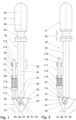
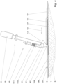
- the Figure 1 shows, in very simplified form, an applicator (10) in a rest position (11).
- the Figure 2 shows this applicator (10) in a position of use (12).
- Such applicators (10) are used to fix microneedle plasters (130) on the skin (1) of a patient, cf. Figure 4 .
- the individual microneedle patch (130) has a large number of microneedles (132), for example of geometrically identical design, on the underside (131) facing away from the applicator (10). These microneedles (132) are held together with a backing layer, not shown here, which is provided by is covered with a plaster (133).
- the microneedles (132) are pressed or pressed into the skin (1) with the help of the applicator (10).
- active ingredients contained in the microneedle plaster (130) can be released into skin layers (3) lying under the cornea (2).
- the plaster (133), cf. Figure 4 protrudes over the area of the microneedles (132) in the longitudinal direction of the plaster (135) and in the transverse direction of the plaster oriented normally thereto.
- the plaster is covered by a sterile barrier (not shown here) and a cover film (136), for example a release liner. Both the sterile barrier and the cover film (136) must be removed before applying the microneedle plaster (130).
- the one in the Figures 1 - 4 Applicator (10) shown comprises a handle (21) and a pressure body (51) connected to it.
- the handle (21) is shown reduced in size compared to the pressure body (51) and the microneedle plaster (130).
- the connection of the pressure body (51) to the handle (21) is designed in the exemplary embodiment as a swivel joint (91) with a reset device (111).
- the handle (21) has a palm body (22) and a finger recess (23). This area of the handle (21) is, for example, rotationally symmetrical with respect to a longitudinal axis (33) of the handle (21).
- the finger recess (23) is a circumferential groove.
- the handle (21) has a support rod (24). In the exemplary embodiment, this has a largely square cross-sectional area.
- the center line of the support rod (24) lies, for example, in the longitudinal axis (33) of the handle (21). At its end facing away from the palm body (22), the support rod (24) has a pivot bolt receptacle (26).
- a pivot bolt (92) is mounted in this pivot bolt receptacle (26), which penetrates the pressure body (51).
- the pivot axis (95) forming the center line of the pivot bolt receptacle (26) is oriented, for example, normal to the longitudinal axis (33) of the handle (21) in the rest position (11).
- the pivot axis (95) can also be aligned skewed to the longitudinal axis (33) in the rest position (11).
- the pressure body (51) is therefore by means of a Swivel joint (91) is pivotably mounted relative to the handle (21).
- the swivel joint (91) has two degrees of freedom (93, 94) oriented in opposite directions.
- the two degrees of pivoting freedom (93, 94) are limited by means of stops (96, 97).
- a first stop (96) limits the pivoting range of the pressure body (51) relative to the handle (21) in the rest position (11).
- This first stop (96) forms a securing element (96) of the applicator (10) in the rest position (11).
- the pivoting range of the pressure body (51) is limited relative to the handle (21) in the use position (12) by means of the second stop (97).
- the applicator (10) can also be designed without the second stop (97). Both the first stop (96) and the second stop (97) can also be arranged differently.
- the pressure body (51) is constructed, for example, in the shape of a prism.
- its cross-sectional area which is oriented normal to the pivot axis (95) corresponds at least approximately to the area of an equilateral triangle.
- the cross-sectional area can also have more than three corners or roundings. It can also be designed asymmetrically.
- the pressure body (51) has a handle holder (52).
- the handle piece (21) is mounted in this handle receptacle (52), which is designed as a recess. It is also conceivable that the handle (21) grips the pressure body (51) on its two end faces, for example parallel to one another.
- the pressure body (51) has, for example, a flat top (53).
- the first stop (96) rests on this top side (53) in the rest position (11) and the second stop (97) in the use position (12).
- the pivot pin recess (54) of the pressure piece (51) is shown in the illustrations Figures 1 and 2 in the direction of the top (53) offset from the geometric center line of the cross-sectional area of the pressure body (51).
- the top (53) is delimited by two flanks (55, 56).
- flanks (55, 56) are, for example, flat surfaces that are connected to one another by means of a pressure surface (57) facing away from the top (53).
- the pressure surface (57) is a uniaxially curved surface.
- the center line of the curvature penetrates the pressure body (51) parallel to the pivot axis (95).
- the curvature radius in this exemplary embodiment is 5 millimeters.
- the pressure surface (57) can also be composed of several arched sections.
- the center lines of these curvature sections which, for example, cover the entire width of the pressure body (51), are then parallel to one another.
- the transitions between the individual curvature sections are continuous.
- the transitions from the pressure surface (57) to the flanks (55, 56) can also be continuous.
- a holder (27, 28) for the reset device (111) is arranged on the support rod (24).
- This holder (27, 28) comprises, for example, two guide tabs (27, 28) attached to the support rod (24).
- These guide tabs (27, 28) can also be parts of the support rod (24). They are spaced apart from one another in the longitudinal direction (25) of the handle (21). In the exemplary embodiment, the distance between the guide tabs (27, 28) is 15% of the length of the support rod (24).
- Each of the guide tabs (27; 28) has a breakthrough (29; 31). For example, both openings (29, 31) are aligned with each other.
- the cross-sectional area of the individual opening (29; 31) can be circular, rectangular, hexagonal, etc.
- the reset device (111) comprises a push rod (112) mounted in the guide tabs (27, 28) and a spring energy store (115) seated on the push rod (112).
- the push rod (112) inserted in the openings (29, 31) lies parallel to the longitudinal direction (25) of the handle (21). Its upper end protrudes from the upper guide tab (27).
- the push rod (112) has a support collar (113) below the lower guide tab (28). For example, this has the shape of a circumferential ring collar.
- the lower one, in the Figures 1 and 2 The pressure end (114) of the pressure rod (112), which contacts the pressure body (51), is hemispherical in the exemplary embodiment.
- the push rod (112) has an indicator (116), for example a marking (116).
- a marking for example, a color ring, a dot, a notch, etc.
- This marking (116) lies within the upper guide tab (27).
- the marking (116) is above the upper guide tab (27).
- the applicator (10) can also give a haptic, acoustic, etc. signal to the operator.
- the push rod (112) With the support collar (113), the push rod (112) carries the spring energy storage (115). In the exemplary embodiment, this is designed as a compression spring (115).
- the compression spring (115) is located in the illustration Figure 1 prestressed to a residual energy value between the support collar (113) and the lower guide tab (28). In this exemplary embodiment, in the rest position (11), this impressed force of the restoring device (111) presses the pressure rod (112) onto the pressure body (51) resting on the securing element (96).
- the spring energy storage (115) can also be fixed to the support collar (113) and to the lower guide tab (28), for example in a form-fitting manner.
- the pressure rod (112) can be connected to the pressure body (51) with its pressure end (114), for example by means of a thrust swivel joint.
- the stops (96, 97) can be omitted.
- the pressure body (51) moves from the rest position (11) towards the use position (12), the pressure body (51) is pivoted about the pivot axis (95).
- the top (53) of the pressure body (51) presses on the ducking end (114) of the pressure rod (112).
- the push rod (112) is pushed upwards.
- the support collar (113) and the lower guide tab (28) compress the compression spring (115) without hysteresis, for example.
- the internal energy of the reset device (111) increases.
- the marking (116) moves upwards so that, for example, the green area above the upper guide tab (27) becomes visible.
- the restoring device (111) can also have a tension spring, a helical torsion spring, a conical helical compression spring, a plate spring package, etc. as a spring energy storage (115). All of these spring energy storage devices (115) are designed in such a way that that in the rest position (11) the reset device (111) has the lowest internal energy.
- the spring energy storage (115) can be completely relieved or have a slight preload.
- the pressure body (51) is constantly loaded in the direction of the rest position (11) relative to the handle (21).
- the respective spring energy storage (115) is additionally loaded. His internal energy is increased. This also increases the restoring force.
- the leg spring when using a helical torsion spring or torsion spring, it encompasses the pivot axis (95) or the pivot bolt (92).
- one leg of the leg spring is fixed, e.g. clamped, to the pressure body (51) and the other leg to the handle (21). In the rest position (11), the leg spring is unloaded, for example. The position of the pressure body (51) relative to the handle (21) is maintained even without the first stop (96). As soon as the pressure body (51) is pivoted out of this position, the legs of the leg spring are pivoted relative to one another about the pivot axis (95). The leg spring is loaded, and the internal energy of the restoring device (111) increases.
- the pressure body (51) can be designed as described above or, for example, as a roller.
- an indicator (116) can, for example, display the angular position of the pressure body (51) relative to the handle (21).
- the microneedle plaster (130) is placed on the patient's skin (1). After removing the cover film (136), the applicator (10) is pulled over the microneedle plaster (130), for example in the longitudinal direction (135) of the plaster, cf. Figure 4 .
- the operator tilts the applicator (10). He presses it against the microneedle plaster (130) in such a way that the rear edge of the plaster (133) in the longitudinal direction of the plaster (135) is first pressed against the patient's skin (1).
- the width of the pressure body (51) in the transverse direction of the plaster is greater than or equal to the width of the microneedle plaster (130).
- the microneedle plaster (130) is fixed to the skin (1) over its entire width in the transverse direction of the plaster (135). This minimizes air pockets, for example
- the pressure body (51) slides with its pressure surface (57) along the surface (134) of the plaster (133).
- An external operating force acts on the pressure surface (57).
- This external operating force is oriented counter to the pulling direction (15) of the applicator (10).
- the external operating force is also oriented parallel to the surface (134) of the microneedle plaster (130). The external operating force thus delays the movement of the applicator (10).
- the pressure body (51) is pivoted about the pivot axis (95) of the pivot joint (91) in the direction of the use position (12).
- the spring energy storage (115) is loaded depending on the level of contact pressure of the pressure body (51) on the microneedle plaster (130). For example, the green marking (116) becomes visible. This signal means to the operator that the contact pressure is, for example, sufficiently large. The operator can continue attaching the microneedle patch (130).
- the pressure body (51) is now in the use position (12) relative to the handle (21) or in an area adjacent to the use position (12).
- the individual microneedles (132) of the microneedle patch (130) are pressed into the skin (1).
- the radius of the pressure surface (57) is at least 1.5 times the product of the circle number ⁇ and the diameter of a needle foot (137).
- the microneedles (132) are pressed in line by line.
- the over-plaster (133) is also attached to the patient's skin (1). After application, the applicator (10) can either be used again or disposed of. When the applicator (10) is removed from the microneedle plaster (130) and from the patient's skin (1), the compressed spring energy storage (115) is relieved.
- the compression spring (115) lengthens. Using the energy released by the reset device (111), the pressure body (51) is returned to the rest position (11) relative to the handle (21).
- the applicator (10) is used in the same way with a differently constructed reset device (111).
- the force applied by the operator relative to the microneedle patch (130) is divided into a tangential component along the microneedle patch (130) and a normal component in the direction of the microneedle patch (130).
- Each one of these force components and thus also the resultant of these components causes the pressing body (51) to pivot relative to the handle (21) in the direction of the use position (12).
- the swivel angle achieved can also be monitored in this exemplary embodiment using a display. This ensures a minimum contact pressure for reliable insertion of the microneedles (132).
- a pressure body (51) designed as a roller it can roll on the microneedle plaster (130) and/or slide along it.
- the Figures 5 - 7 show a unit (150) consisting of an applicator (10) and a microneedle plaster (130) as well as the pressure body (51) as an individual part.
- the unit (150) for example, is supplied for one-time use.
- the microneedle plaster (130) carries the cover film (136) on the overplaster (133).
- the applicator (10) is arranged on the edge of the plaster (133) and the cover film (136), the handle (21) of which rests on the cover film (136).
- the applicator (10) in this exemplary embodiment is largely constructed in the same way as in connection with the one in the Figures 1 - 4 illustrated embodiment described.
- the spring energy storage (115) for example, is positively connected to both the support collar (113) and the lower guide tab (28).
- the handle (21) lies in a distribution position (32) in which its longitudinal direction (25) forms an angle of, for example, 65 degrees to a connecting plane (58) spanned by the pivot axis (95) and the radius center line of the pressure surface (57).
- the connecting plane (58) for example, closes the same angle this representation with the longitudinal direction of the pavement (135).
- the ratio of the radius of the pressure surface (57) to the diameter of the needle foot (137) or to the length of the needle foot (137) in the longitudinal direction (135) of the plaster corresponds to the above-mentioned ratio in this exemplary embodiment.
- FIG. 6 a longitudinal section of the pressure body (51) of this applicator (10) is shown.
- the cutting plane of this representation lies in the vertical central longitudinal plane of the applicator (10).
- the pivot pin recess (54), the pressure surface (57), the rear flank (55) and the top (53) are designed as described in connection with the first exemplary embodiment.
- the handle holder (52) is open towards the front flank (56). This means that the handle (21) is stored in the sales position (32), for example without a stop.
- a detent or wedge lock (61) is arranged in the handle receptacle (52) on at least one recess surface (59) oriented parallel to the vertical central longitudinal plane.
- the wedge surface (63) pointing in the direction of the connecting plane (58) is a locking surface.
- the front flank (56) comprises two guide surfaces (64, 65), which are separated from one another by a separating edge (66).
- the separating edge (66) runs parallel to the pivot axis (95). It protrudes from the pressure body (51) at an acute angle in the pulling direction (15).
- the two concavely curved guide surfaces (64, 65) for example, form an angle of 10 degrees to 20 degrees. In the exemplary embodiment, the included angle is 17 degrees.
- the plane of the bisector of the separating edge (66) forms the same angle with the connecting plane (58) as the longitudinal direction of the pavement (135) with the connecting plane (58).
- both guide surfaces (64, 65) are composed of several uniaxial curvature sections lying parallel to one another.
- the pressure body () has the same cross-sectional area over its entire width - with the exception of the handle holder (52).
- the imaginary center lines of the individual curvature sections of both guide surfaces (64, 65) lie parallel to the pivot axis (95). These center lines are offset from the pressure body (51) in the pulling direction (15).
- the lower guide surface (64) merges continuously into the pressure surface (57). For example, its curvature radius decreases from the separating edge (66).
- the lower guide surface (64) then merges tangentially into the oppositely curved pressure surface (57).
- the upper guide surface (65) is shown in the illustration Figure 6 a radius of curvature that expands spirally from the separating edge (66).
- the tangential plane at the upper outlet (67) of the upper guide surface (65) is parallel to the plane of the bisector of the separating edge (66).
- the upper guide surface (65) collides with the top side (53) of the pressure body (51) in a longitudinal edge (68).
- the pressure body (51) carries a guide element (71) on each of the end faces (69).
- the pressure body (51) and the two guide elements (71) form a pressure body group (50).
- both guide elements (71) which are mirror images of one another, are rigidly connected to the pressure body (51).
- they are molded.
- the pivot axes of both guide elements (71), which are aligned with one another in pivotable guide elements (71), lie parallel to the radius center line of the pressure surface (57).
- the individual guide element (71) has a guide plate (72) and two guide webs pointing in the direction of the vertical central longitudinal plane of the pressure body (51). (73, 74).
- the guide plates (72) lie parallel to the vertical central longitudinal plane on the outer sides of the pressure body (51). For example, you have a cuboid envelope contour. At their lower end, which points towards the pressure surface (57), they have a notch (75).
- the guide webs (73, 74) are flat. At their end pointing in the direction of the pressure surface (57), they taper in an arc shape from the inside to the outside.
- the respective central axis of the radius corresponds, for example, to the central axis of the curvature section of the respective adjacent guide surface (64; 65).
- the distance between the upper taper (76) and the upper guide surface (65) corresponds to the thickness of the cover film (136).
- the distance between the lower taper (77) and the lower guide surface (64) corresponds to the thickness of the plaster (133).
- the Figure 8 shows a detail of the microneedle plaster (130) with the cover film (136).
- the right edge of the microneedle plaster (130) seen in the longitudinal direction (135) of the plaster is shown.
- the cover film (136) is positively connected to the microneedle plaster (130) on both long sides (139).
- the cover film (136) has an elastically deformable longitudinal nose (141), which engages in an elastically deformable longitudinal groove (142) with a grip (143) of the microneedle plaster (130).
- the applicator (10) reaches with the separating edge (66) into the space between the cover film (136) and the plaster (133).
- the upper guide bar (73) rests on the cover film (136).
- the lower guide bar (74) contacts the underside (131) of the plaster (133).
- the cover film (136) has a free end in an upper guide path (78) between the separating edge (66) and the upper guide web (73) and between the upper taper (76) and the upper guide surface (65). For example, the cover film (136) is already in contact with the upper guide surface (65).
- the plaster (133) is guided along the lower guide path (79). This runs between the separating edge (66) and the lower guide web (74) and between the lower taper (77) and the lower guide surface (64).
- the plaster (133) is in the Figure 5 shown distribution position (32) up to below the pressure surface (57).
- microneedle plaster (130) In order to use the microneedle plaster (130), it is glued to the patient's skin (1) with the end of the plaster (133) on which the applicator (10) is located.
- the handle (21) is made from the one in the Figure 5
- the sales position (32) shown is folded out until, for example, the detent or wedge lock (61) is activated.
- the pressure body (51) is now in the rest position (11) relative to the handle (21).
- the spring energy storage (115) is not loaded or only slightly loaded.
- the applicator (10) is pressed in the longitudinal direction (25) of the handle (21). Since when pulling, the longitudinal direction (25) forms an angle with the connecting plane (58) that is not equal to 0 degrees and 180 degrees, a torque around the instantaneous pole line (81) acts on the pressure body (51).
- This instantaneous pole line (81) is the contact line of the pressure surface (57) with the plaster (133).
- the spring energy storage (115) is loaded until the spring force and the force applied by the operator reach equilibrium. At the same time, for example, the marking (116) moves into the visible area.
- the separating edge (66) separates the connection between the cover film (136) and the plaster (133).
- the cover film (136) is guided along the upper guide surface (65) and, for example, lies loosely on the area of the cover film (136) that has not yet been processed.
- microneedle plaster (130) with the overplaster (133) is guided down to the pressure surface (57) by means of the separating edge (66).
- the microneedles (132) are pressed into the skin (1) line by line, for example.
- the plaster (133) is pressed onto the skin (1) and adheres there adhesively.
- the cover film (136) is completely removed.
- the applicator (10) has detached from the microneedle patch (130).
- the Figure 9 shows an applicator (10) with a push joint (101).
- This thrust joint (101) connects a pressure body group (50) to the handle (21).
- the thrust joint (101) consists of a hollow prism (102) in which a solid prism (103) is guided telescopically.
- the handle (21) is constructed largely as described in connection with the first exemplary embodiment.
- the support rod (24) has an area of circular cross-section which ends at, for example, a circumferential retaining collar (34).
- the hollow prism (102) is centrally formed on this retaining collar (34). This is, for example, a hollow rod with a circular cross-sectional area.
- this hollow prism (102) has an elongated hole-like longitudinal slot (104) oriented in the longitudinal direction (25).
- the support rod (24) can also have a different, for example a square, cross-sectional area.
- the retaining collar (34) can consist of individual segments or sections.
- the hollow prism (102) can also have, for example, a square cross-sectional area or another cross-sectional area that deviates from a circular cross-sectional area.
- the pressure body group (50) comprises a pressure body (51) and a guide rod (82) arranged on the pressure body (51).
- the pressure body (51) for example, is constructed largely as described in connection with the first exemplary embodiment.
- the guide rod (82) is rigidly connected to the pressure body (51). It protrudes from this in the longitudinal direction (25).
- the guide rod (82) has a cylindrical area (83), from which the solid prism (103), which is also cylindrical, protrudes centrally.
- the transition between the cylindrical area (83) and the full prism (103), which is designed as a cylindrical rod, is formed by, for example, a circumferential support collar (84).
- the support collar (84) can be designed like the retaining collar (34).
- the cross-sectional area of the solid prism (103) is geometrically similar to the inner cross-sectional area of the hollow prism (102), so that the hollow prism (102) can accommodate and guide the solid prism (103).
- the solid prism (103) has a spring-loaded locking pin (105), for example, which engages in the longitudinal slot (104) of the hollow prism (102) when the push joint (101) is installed.
- Other designs of anti-twist protection and pull-out protection are also conceivable.
- the pressure body (51) can also be designed as a roller in this exemplary embodiment.
- the roller radius corresponds, for example, to the above-mentioned radius of the pressure surface (57).
- the pressure body (51) is then rotatably mounted on both end faces on a fork-shaped guide rod (82).
- the reset device (111) also comprises a spring energy storage (115) in the form of a compression spring (115).
- a spring energy storage in the form of a compression spring (115).
- the compression spring (115) can, for example, be fixed in a form-fitting manner on the support collar (84) and on the retaining collar (34).
- the applicator (10) can then be designed without additional pull-out protection.
- the spring energy storage (115) can also be designed as a plate spring package, as a conical helical compression spring, etc.
- the thrust joint (101) can, for example, have a haptic indicator (116).
- the push joint (101) is designed in such a way that a locking lug must be overcome shortly before reaching the position of use (12). The resistance felt by the operator increases briefly when overcoming the locking lug and then suddenly drops again.
- the locking lug can have differently designed flanks so that the operator receives a different haptic signal if the contact pressure is accidentally reduced.
- An optical or an acoustic indicator (116) are also conceivable.
- the operator pulls the applicator (10) over the microneedle plaster (130) after removing the cover film (136).
- the applicator (10) can be held vertically or at an angle, with the handle (21) being inclined, for example, in the direction of the longitudinal direction (135) of the plaster.
- the applicator (10) is then pulled.
- the compression spring (115) is compressed.
- the operator is informed whether the contact pressure is sufficient or needs to be increased.
- the Figures 10 - 12 show an applicator (10) with an integrated dispensing device (121).
- the handle (21) of this applicator (10) is designed as a housing (35) in which the dispensing device (121) for a microneedle plaster (130) and a pressure body group (50) are arranged.
- the dispensing device (121) comprises, for example, six cylindrical bearing rollers (122 - 125).
- two of these bearing rollers (122, 123) are rotatably mounted above the cover film (136) of a microneedle plaster (130) and, for example, four bearing rollers (124, 125) below this microneedle plaster (130) in the housing (35).
- the microneedles (132) of the microneedle patch (130) point downwards.
- the individual bearing rollers (122 - 125) can also be moved using a linkage be connected to each other.
- the bearing rollers (122, 124; 123, 125) lying opposite one another above and below the microneedle patch (130) can also be loaded against one another, for example by means of a tension spring.
- the axes of rotation (126) of all bearing rollers (122 - 125) are aligned parallel to one another.
- the upper bearing rollers (122, 123) are, for example, continuous. Your roll length, oriented transversely to the longitudinal direction of the plaster (135), is greater than or equal to the width of the microneedle plaster (130). However, it is also conceivable to replace each of these upper bearing rollers (122; 123) with two individual rollers, the roller length of which is, for example, shorter than half the width of the pavement.
- the lower bearing rollers (124, 125) are short rollers (124, 125). Its length in the transverse direction of the plaster corresponds, for example, to the width of the lateral projection (138) of the plaster (133) over the microneedles (132).
- the bearing rollers (122 - 125) can rotate freely or with brakes. The normal force of the tension spring mentioned can also increase the rolling or rolling resistance of the bearing rollers (122 - 125).
- the microneedle patch (130), for example, is designed largely as described in connection with the previous exemplary embodiments.
- the longitudinal direction of the plaster (135) forms an angle between, for example, between 30 degrees and 60 degrees, for example 45 degrees, with the longitudinal direction (25) of the handle (21).
- the cover film (136), for example, adheres over the entire surface to the microneedle plaster (130).
- the cover film (136) can also be connected to the microneedle plaster (130), as in connection with the exemplary embodiment Figures 5 - 8 described.
- the plaster (133) and the cover film (136) are separated from each other.
- the pressure body group (50) is pivotally mounted in the housing (35) in a swivel joint (91).
- the pivot axis (95) of the pivot joint (91) is arranged in the axis of rotation (126) of the first upper bearing roller (122).
- the pressure body group (50) comprises a pressure body (51) and a fork-shaped lever arm (85).
- This lever arm (85) is mounted in the pivot bearing (91).
- the fork (86) of the lever arm (85) carries an axle rod (87) on which the pressure body (51), designed as a cylindrical roller, is rotatably mounted.
- the radius of the roller (51) corresponds, for example, to the radius of the in connection with the exemplary embodiment Figure 9 described roller-shaped pressure body (51).
- the envelope contour of the pressure body (51) can then correspond to the envelope contour of one of the non-rotatable pressure bodies (51) described in connection with the aforementioned exemplary embodiments.
- the applicator (10) has an internal reset device (111) arranged in the housing (35).
- This comprises a spring energy storage device (115) which is supported on the housing (35) and on a yoke-like spring plate (117).
- the yoke arms (118) of the spring plate (117) surround the pressure body (51) on its end faces (69). They are connected to the axle rod (87) of the pressure body (51). For example, they are pivotally mounted on the axle rod (87).
- the spring energy storage (115) is designed as a compression spring (115).
- the spring energy storage (115) it is also conceivable to design the spring energy storage (115) as a plate spring package, as a tension spring, etc.
- the spring plate (117) is shown in the illustrations Figures 10 - 12 a pointer arm (119) with an indicator (116) is arranged.
- the housing (35) has, for example, a viewing window (36). Through this the indicator (116) is in the representation Figure 10 invisible. In the representations of the Figures 11 and 12 , which show the loaded applicator (10), the indicator (116) is visible through the viewing window (36).
- a retaining hook (37) is also attached to the housing (35). This penetrates and engages behind the spring plate (117). This holding hook (37) protects the restoring device (111) from lifting off.
- the bottom (38) of the housing (35) has an opening (39) through which the Figure 10 the paving (133) protrudes through. It is also conceivable that in the shipping position of the applicator (10) the opening (39) is closed.
- the microneedle plaster (130) is then inserted, for example, by means of a slider, a crank, etc. that can be actuated from the outside of the housing (35). Figure 10 preparedness situation shown (13).
- a guide wedge (42) is arranged in the housing interior (41) on the bottom (38) between the opening (39) and the pressure body (51). This has a separating edge (43) and a guide surface (44) adjacent to the separating edge (43) and oriented in the direction of the housing interior (41).
- the guide surface (44) can, for example, be designed like the upper guide surface (65) in the Figures 5 - 8 illustrated embodiment.
- Figure 6 in an applicator (10).
- Figure 10 the guide wedge (42) can be omitted.
- the pressure body group (50) from the exemplary embodiment Figures 5 - 8 replace the guide wedge (42) and the pressure body (51).
- the guide elements (71) can also be arranged on the housing side.
- the microneedle plaster (130) is pulled out of the dispensing device (121), see Figure 11.
- the pressure body (51) is pressed in the direction of the position of use (12), whereby the reset device (111) is loaded.
- the indicator (116) becomes visible in the viewing window (36).
- the microneedle plaster (130) is pressed onto the patient's skin (1), with the microneedles (132) being pressed into the skin (1).
- the pressure body (51) rolls on the microneedle plaster (130).
- all microneedles (132) are pressed in.
- the microneedle plaster (130) is fixed on the skin (1), cf. Figure 12 .
Landscapes
- Health & Medical Sciences (AREA)
- Dermatology (AREA)
- Engineering & Computer Science (AREA)
- Veterinary Medicine (AREA)
- Life Sciences & Earth Sciences (AREA)
- Public Health (AREA)
- General Health & Medical Sciences (AREA)
- Animal Behavior & Ethology (AREA)
- Hematology (AREA)
- Anesthesiology (AREA)
- Heart & Thoracic Surgery (AREA)
- Biomedical Technology (AREA)
- Medical Informatics (AREA)
- Chemical & Material Sciences (AREA)
- Medicinal Chemistry (AREA)
- Pharmacology & Pharmacy (AREA)
- Epidemiology (AREA)
- Media Introduction/Drainage Providing Device (AREA)
Description
- Die Erfindung betrifft einen Applikator mit einem Griffstück und mit einem mit dem Griffstück verbundenen Druckkörper für ein Mikronadelpflaster sowie eine Einheit aus einem derartigen Applikator und einem Mikronadelpflaster mit einer Vielzahl von Mikronadeln.
- Aus der
US 2018/0177991 A1 ist ein Applikator für ein Mikronadelpflaster bekannt. Die Nadeln werden beim Abrollen des Stempels mittels des variierenden Normalkraftanteils in die Haut des Patienten eingedrückt. - Der vorliegenden Erfindung liegt die Aufgabe zugrunde, ein weitgehend gleichförmiges Einpressen der Mikronadeln zu ermöglichen.
- Diese Problemstellung wird mit den Merkmalen des Hauptanspruchs gelöst. Dazu ist der Druckkörper relativ zum Griffstück in einem Schubgelenk oder in einem Schwenkgelenk zumindest zwischen einer Ruhestellung und einer Gebrauchsstellung mittels äußerer Betriebskräfte und einer internen Rückstellvorrichtung verstellbar gelagert. Der Druckkörper weist eine vom Schwenkgelenk oder Schubgelenk beabstandete Andruckfläche auf. In der Ruhestellung ist der Druckkörper von äußeren Betriebskräften unbelastet und die Rückstellvorrichtung weist die geringste innere Energie auf. Außerdem ist der Druckkörper mittels an der Andruckfläche angreifenden äußeren Betriebskräften relativ zum Griffstück in Richtung der Gebrauchsstellung unter Erhöhung der inneren Energie der Rückstellvorrichtung verstellbar.
- In der Einheit aus dem Applikator und dem Mikronadelpflaster beträgt der kleinste Radius der Andruckfläche mindestens dem anderthalbfachen Produkt aus der Kreiszahl π und der Länge des Nadelfußes in der Pflasterlängsrichtung. Diese Länge ist z.B. bei einer kegelförmigen Mikronadel der Durchmesser des Nadelfußes. Bei einer pyramidenförmigen Mikronadel entspricht diese Länge je nach Anordnung der Mikronadel zur Pflasterlängsrichtung z.B. der Kantenlänge oder der Diagonalen des Nadelfußes. Auch andere Gestalten der Mikronadeln sind denkbar.
- Der Druckkörper ist relativ zum Griffstück schwenkbar oder längsverschieblich gelagert. In der Ruhestellung wirken die geringsten Kräfte auf den Druckkörper und auf das Schub- oder Schwenkgelenk. Die Rückstellvorrichtung ist entlastet.
- Sobald der Bediener den Applikator auf das Mikronadelpflaster drückt und/oder den Applikator entlang des Mikronadelpflasters z.B. zieht, greift eine äußere Betriebskraft an der Andruckfläche an. Der Druckkörper wird relativ zum Griffstück in Richtung der Gebrauchsstellung geschwenkt oder geschoben. Hierbei wird die Rückstellvorrichtung belastet. Die beim Belasten der Rückstellvorrichtung erzeugte Rückstellkraft korreliert mit der vom Bediener aufgebrachten Kraft und mit der Anpresskraft des Applikators auf das Mikronadelpflaster. Damit werden beim Ziehen oder Schieben des Applikators entlang des Mikronadelpflasters die Mikronadeln gleichmäßig in die Haut eingepresst und mit Hilfe eines Überpflasters befestigt.
- Als Druckkörper kann ein Gleitkörper oder ein Wälzkörper eingesetzt werden. Der Druckkörper hat eine gewölbte Andruckfläche. Die Wölbung ist stetig ausgebildet. Sie kann einen konstanten Radius aufweisen oder aus mehreren Bereichen unterschiedlicher Radien zusammengesetzt sein. Sämtliche Radiusmittellinien der Andruckfläche liegen parallel zueinander. Beispielsweise liegt jede Radiusmittellinie in einer Normalenebene zu einer Längsrichtung des Griffstücks. Zumindest in der Gebrauchsstellung ist zumindest die Wölbungsradius-Mittellinie mit dem kleinsten Wölbungsradius windschief zur Längsachse des Griffstücks. Die Wölbungsradius-Mittellinie hat damit keinen Schnittpunkt mit der Längsachse.
- Der kleinste Radius der Andruckfläche wird in Abhängigkeit der Geometrie der Mikronadeln des Mikronadelpflasters gewählt. Hiermit kann ein Verkanten der Mikronadeln beim Einbringen in die Haut verhindert werden.
- Weitere Einzelheiten der Erfindung ergeben sich aus den Unteransprüchen und den nachfolgenden Beschreibungen schematisch dargestellter Ausführungsbeispiele.
-
Figur 1 : Applikator in der Ruhestellung; -
Figur 2 : Applikator in der Gebrauchsstellung; -
Figur 3 : Rückansicht des Applikators; -
Figur 4 : Applikator beim Fixieren des Mikronadelpflasters auf der Haut; -
Figur 5 : Einheit aus Applikator und Mikronadelpflaster; -
Figur 6 : Schnitt des Druckkörpers der Einheit ausFigur 5 ; -
Figur 7 : Einheit ausFigur 5 beim Aufbringen des Mikronadelpflasters; -
Figur 8 : Detail des Mikronadelpflasters mit der Abdeckfolie; -
Figur 9 : Applikator mit Schubgelenk; -
Figur 10 : Applikator mit Spendiervorrichtung in der Bereitschaftsstellung; -
Figur 11 : Applikator ausFigur 10 beim Applizieren; -
Figur 12 : Applikator ausFigur 10 nach dem Aufbringen des Mikronadelpflasters. - Die
Figur 1 zeigt stark vereinfacht einen Applikator (10) in einer Ruhestellung (11). DieFigur 2 zeigt diesen Applikator (10) in einer Gebrauchsstellung (12). Derartige Applikatoren (10) werden eingesetzt, um Mikronadelpflaster (130) auf der Haut (1) eines Patienten zu fixieren, vgl.Figur 4 . Das einzelne Mikronadelpflaster (130) hat auf der dem Applikator (10) abgewandten Unterseite (131) eine Vielzahl z.B. geometrisch identisch ausgebildeter Mikronadeln (132). Diese Mikronadeln (132) werden mit einem hier nicht dargestellten Backing Layer zusammengehalten, der von einem Überpflaster (133) überdeckt ist. Bei der Applikation werden die Mikronadeln (132) mit Hilfe des Applikators (10) in die Haut (1) eingedrückt oder eingepresst. Nach dem Befestigen des Mikronadelpflasters (130) auf der Haut (1) können z.B. im Mikronadelpflaster (130) enthaltene Wirkstoffe in unter der Hornhaut (2) liegende Hautschichten (3) abgegeben werden. - Das Überpflaster (133), vgl.
Figur 4 , steht in der Pflasterlängsrichtung (135) und in der normal hierzu orientierten Pflasterquerrichtung über den Bereich der Mikronadeln (132) über. Im Lieferzustand, vgl. z.B.Figur 8 , ist das Überpflaster mittels einer hier nicht dargestellten Sterilbarriere und einer Abdeckfolie (136), z.B. eines Release liners, abgedeckt. Sowohl die Sterilbarriere als auch die Abdeckfolie (136) sind vor dem Applizieren des Mikronadelpflasters (130) zu entfernen. - Der in den
Figuren 1 - 4 dargestellte Applikator (10) umfasst ein Griffstück (21) und einen mit diesem verbundenen Druckkörper (51). In allen Darstellungen ist das Griffstück (21) im Vergleich zum Druckkörper (51) und zum Mikronadelpflaster (130) verkleinert dargestellt. Die Verbindung des Druckkörpers (51) mit dem Griffstück (21) ist im Ausführungsbeispiel als Schwenkgelenk (91) mit einer Rückstellvorrichtung (111) ausgebildet. - Das Griffstück (21) hat einen Handballenkörper (22) und eine Fingerausnehmung (23). Dieser Bereich des Griffstücks (21) ist beispielsweise rotationssymmetrisch in Bezug auf eine Längsachse (33) des Griffstücks (21) ausgebildet. Die Fingerausnehmung (23) ist in diesem Ausführungsbeispiel eine umlaufende Rinne. Weiterhin hat das Griffstück (21) eine Tragstange (24) Diese hat im Ausführungsbeispiel eine weitgehend quadratische Querschnittsfläche. Die Mittellinie der Tragstange (24) liegt z.B. in der Längsachse (33) des Griffstücks (21). An ihrem dem Handballenkörper (22) abgewandten Ende hat die Tragstange (24) eine Schwenkbolzenaufnahme (26). In dieser Schwenkbolzenaufnahme (26) ist im Ausführungsbeispiel ein Schwenkbolzen (92) gelagert, der den Druckkörper (51) durchdringt. Die die Mittellinie der Schwenkbolzenaufnahme (26) bildende Schwenkachse (95) ist in der Ruhestellung (11) z.B. normal zur Längsachse (33) des Griffstücks (21) orientiert. Die Schwenkachse (95) kann in der Ruhestellung (11) auch windschief zur Längsachse (33) ausgerichtet sein. Der Druckkörper (51) ist somit mittels eines Schwenkgelenks (91) relativ zum Griffstück (21) schwenkbar gelagert. Das Schwenkgelenk (91) hat zwei einander entgegengesetzt orientierte Freiheitsgrade (93, 94). Die beiden Schwenkfreiheitsgrade (93, 94) sind in diesem Ausführungsbeispiel mittels Anschlägen (96, 97) begrenzt. In der Darstellung der
Figur 1 begrenzt ein erster Anschlag (96) den Schwenkbereich des Druckkörpers (51) relativ zum Griffstück (21) in der Ruhestellung (11). Dieser erste Anschlag (96) bildet ein Sicherungselement (96) des Applikators (10) in der Ruhestellung (11). Gemäß derFigur 2 wird der Schwenkbereich des Druckkörpers (51) relativ zum Griffstück (21) in der Gebrauchsstellung (12) mittels des zweiten Anschlags (97) begrenzt. Der Applikator (10) kann auch ohne den zweiten Anschlag (97) ausgebildet sein. Sowohl der erste Anschlag (96) als auch der zweite Anschlag (97) können auch anders angeordnet sein. - Der Druckkörper (51) ist z.B. prismenförmig aufgebaut. Im Ausführungsbeispiel entspricht seine normal zur Schwenkachse (95) orientierte Querschnittsfläche zumindest annähernd der Fläche eines gleichseitigen Dreiecks. Die Querschnittsfläche kann auch mehr als drei Ecken oder Abrundungen aufweisen. Sie kann auch unsymmetrisch ausgebildet sein. Im mittleren Bereich der Schwenkachse (95), vgl. Figur 3, hat der Druckkörper (51) eine Griffstückaufnahme (52). In dieser als Aussparung ausgebildeten Griffstückaufnahme (52) ist das Griffstück (21) gelagert. Es ist auch denkbar, dass das Griffstück (21) den Druckkörper (51) an dessen beiden z.B. zueinander parallelen Stirnseiten greift. Im Ausführungsbeispiel hat der Druckkörper (51) eine z.B. ebene Oberseite (53). An dieser Oberseite (53) liegt in der Ruhestellung (11) der erste Anschlag (96) und in der Gebrauchsstellung (12) der zweite Anschlag (97) an. Die Schwenkbolzenausnehmung (54) des Druckstücks (51) ist in den Darstellungen der
Figuren 1 und 2 in Richtung der Oberseite (53) versetzt zur geometrischen Mittellinie der Querschnittsfläche des Druckkörpers (51). - Die Oberseite (53) wird im Ausführungsbeispiel von zwei Flanken (55, 56) begrenzt. Dies sind z.B. ebene Flächen, die mittels einer der Oberseite (53) abgewandten Andruckfläche (57) miteinander verbunden sind. Die Andruckfläche (57) ist in diesem Ausführungsbeispiel eine einachsig gewölbte Fläche. Die Mittellinie der Wölbung durchdringt den Druckkörper (51) parallel zur Schwenkachse (95). Der Wölbungsradius beträgt in diesem Ausführungsbeispiel 5 Millimeter. Die Andruckfläche (57) kann auch aus mehreren Wölbungsabschnitten zusammengesetzt sein. Die Mittellinien dieser Wölbungsabschnitte, die z.B. die gesamte Breite des Druckkörpers (51) umfassen, liegen dann parallel zueinander. Die Übergänge zwischen den einzelnen Wölbungsabschnitten sind stetig ausgebildet. Auch die Übergänge der Andruckfläche (57) zu den Flanken (55, 56) können stetig ausgebildet sein.
- An der Tragstange (24) ist im Ausführungsbeispiel eine Halterung (27, 28) für die Rückstellvorrichtung (111) angeordnet. Diese Halterung (27, 28) umfasst z.B. zwei an der Tragstange (24) befestigte Führungslaschen (27, 28). Diese Führungslaschen (27, 28) können auch Teile der Tragstange (24) sein. Sie sind in der Längsrichtung (25) des Griffstücks (21) zueinander beabstandet. Im Ausführungsbeispiel beträgt der Abstand der Führungslaschen (27, 28) zueinander 15 % der Länge der Tragstange (24). Jede der Führungslaschen (27; 28) hat einen Durchbruch (29; 31). Beispielsweise fluchten beide Durchbrüche (29, 31) miteinander. Die Querschnittsfläche des einzelnen Durchbruchs (29; 31) kann kreisförmig, rechteckig, sechseckig, etc. ausgebildet sein.
- Die Rückstellvorrichtung (111) umfasst eine in den Führungslaschen (27, 28) gelagerte Druckstange (112) und einen auf der Druckstange (112) sitzenden Federenergiespeicher (115). Die in den Durchbrüchen (29, 31) steckende Druckstange (112) liegt parallel zur Längsrichtung (25) des Griffstücks (21). Ihr oberes Ende ragt aus der oberen Führungslasche (27) heraus. Unterhalb der unteren Führungslasche (28) hat die Druckstange (112) einen Stützbund (113). Dieser hat beispielsweise die Gestalt eines umlaufenden Ringbunds. Das untere, in den
Figuren 1 und 2 den Druckkörper (51) kontaktierende Druckende (114) der Druckstange (112) ist im Ausführungsbeispiel halbkugelförmig ausgebildet. - Im oberen Bereich hat die Druckstange (112) einen Indikator (116), z.B. eine Markierung (116). Dies ist beispielsweise ein Farbring, ein Punkt, eine Kerbe, etc. In der Darstellung der
Figur 1 liegt diese Markierung (116) innerhalb der oberen Führungslasche (27). In der in derFigur 2 gezeigten Gebrauchsstellung (12) steht die Markierung (116) oberhalb der oberen Führungslasche (27). Anstatt einer einzelnen Markierung (116) ist es denkbar, z.B. untereinander abgeordnete verschiedenfarbige Markierungen auf der Druckstange (112) anzubringen. Beispielsweise könnte die oberste Markierung rot, eine mittlere Markierung gelb und die unterste Markierung (116) grün sein. Anstatt des beschriebenen optischen Signals mittels der Markierung (116) kann der Applikator (10) auch ein haptisches, akustisches, etc. Signal an den Bediener geben. - Mit dem Stützbund (113) trägt die Druckstange (112) den Federenergiespeicher (115). Dieser ist im Ausführungsbeispiel als Druckfeder (115) ausgebildet. Die Druckfeder (115) sitzt in der Darstellung der
Figur 1 auf einen Restenergiewert vorgespannt zwischen dem Stützbund (113) und der unteren Führungslasche (28). Diese eingeprägte Kraft der Rückstellvorrichtung (111) drückt in diesem Ausführungsbeispiel in der Ruhestellung (11) die Druckstange (112) auf den am Sicherungselement (96) anliegenden Druckkörper (51). - Der Federenergiespeicher (115) kann auch am Stützbund (113) und an der unteren Führungslasche (28) z.B. formschlüssig fixiert sein. Weiterhin kann die Druckstange (112) mit ihrem Druckende (114) z.B. mittels eines Schub-Schwenkgelenks mit dem Druckkörper (51) verbunden sein. Bei derartigen Ausführungen können z.B. die Anschläge (96, 97) entfallen.
- Bei einer Bewegung des Druckkörpers (51) aus der Ruhestellung (11) in Richtung der Gebrauchsstellung (12) wird der Druckkörper (51) um die Schwenkachse (95) geschwenkt. Die Oberseite (53) des Druckkörpers (51) drückt auf das Duckende (114) der Druckstange (112). Die Druckstange (112) wird nach oben verdrängt. Hierbei komprimieren der Stützbund (113) und die untere Führungslasche (28) z.B. hysteresefrei die Druckfeder (115). Die innere Energie der Rückstellvorrichtung (111) steigt an. Gleichzeitig wandert die Markierung (116) nach oben, sodass beispielsweise der grüne Bereich oberhalb der oberen Führungslasche (27) sichtbar wird. Beim Entlasten des Druckkörpers (51) schnellt dieser wieder unter Entladung des Federenergiespeichers (115) in die Ruhestellung (11) zurück.
- Die Rückstellvorrichtung (111) kann als Federenergiespeicher (115) auch eine Zugfeder, eine Schrauben-Drehfeder, eine kegelige Schrauben-Druckfeder, ein Tellerfederpaket, etc. aufweisen. Alle diese Federenergiespeicher (115) sind so ausgebildet, dass in der Ruhestellung (11) die Rückstellvorrichtung (111) die geringste innere Energie hat. Der Federenergiespeicher (115) kann hierbei vollständig entlastet sein oder eine geringe Vorspannung aufweisen. Beim Einsatz eines Federenergiespeichers (115) mit Vorspannung wird der Druckkörper (51) relativ zum Griffstück (21) ständig in Richtung der Ruhestellung (11) belastet. Bei einer Bewegung des Druckkörpers (51) in Richtung der Gebrauchsstellung (12) wird der jeweilige Federenergiespeicher (115) zusätzlich belastet. Seine innere Energie wird erhöht. Damit steigt auch die Rückstellkraft an.
- Beispielsweise beim Einsatz einer Schrauben-Drehfeder bzw. Schenkelfeder umgreift diese die Schwenkachse (95) bzw. den Schwenkbolzen (92). Beispielsweise ist ein Schenkel der Schenkelfeder am Druckkörper (51) und der andere Schenkel am Griffstück (21) fixiert, z.B. geklemmt. In der Ruhestellung (11) ist die Schenkelfeder z.B. unbelastet. Die Position des Druckkörpers (51) relativ zum Griffstück (21) wird auch ohne den ersten Anschlag (96) gehalten. Sobald der Druckkörper (51) aus dieser Lage ausgeschwenkt wird, werden die Schenkel der Schenkelfeder relativ zueinander um die Schwenkachse (95) verschwenkt. Die Schenkelfeder wird belastet, wobei die innere Energie der Rückstellvorrichtung (111) zunimmt. Der Drucckörper (51) kann wie oben beschrieben oder beispielsweise als Rolle ausgebildet sein. In diesem Ausführungsbeispiel kann ein Indikator (116) beispielsweise die Winkellage des Druckkörpers (51) relativ zum Griffstück (21) anzeigen.
- Vor dem Einsatz des in den
Figuren 1 bis 4 dargestellten Applikators (10) wird das Mikronadelpflaster (130) auf die Haut (1) des Patienten aufgelegt. Nach dem Entfernen der Abdeckfolie (136) wird der Applikator (10) z.B. in Pflasterlängsrichtung (135) über das Mikronadelpflaster (130) gezogen, vgl.Figur 4 . Beim Ziehen stellt der Bediener den Applikator (10) schräg. Er drückt ihn so gegen das Mikronadelpflaster (130), dass zunächst der in der Pflasterlängsrichtung (135) hintere Rand des Überpflasters (133) an die Haut (1) des Patienten angepresst wird. Die Breite des Druckkörpers (51) in der Pflasterquerrichtung ist größer oder gleich der Breite des Mikronadelpflasters (130). Das Mikronadelpflaster (130) wird auf der ganzen Breite in der Pflasterquerrichtung (135) auf der Haut (1) fixiert. Hiermit werden z.B. Lufteinschlüsse minimiert- - Beim Ziehen des Applikators (10) und Anpressen des Druckkörpers (51) an das Mikronadelpflaster (130) gleitet der Druckkörper (51) mit seiner Andruckfläche (57) entlang der Oberfläche (134) des Überpflasters (133). Auf die Andruckfläche (57) wirkt eine äußere Betriebskraft. Diese äußere Betriebskraft ist entgegen der Zugrichtung (15) des Applikators (10) orientiert. Zumindest im Bereich des Überpflasters (133) ist die äußere Betriebskraft auch parallel zur Oberfläche (134) des Mikronadelpflasters (130) orientiert. Die äußere Betriebskraft verzögert damit die Bewegung des Applikators (10). Der Druckkörper (51) wird um die Schwenkachse (95) des Schwenkgelenks (91) in Richtung der Gebrauchsstellung (12) geschwenkt. Der Federenergiespeicher (115) wird in Abhängigkeit der Höhe der Anpresskraft des Druckkörpers (51) auf das Mikronadelpflaster (130) belastet. Beispielsweise wird die grüne Markierung (116) sichtbar. Dieses Signal bedeutet für den Bediener, dass die Anpresskraft z.B. genügend groß ist. Der Bediener kann das Befestigen des Mikronadelpflasters (130) fortsetzen. Der Druckkörper (51) befindet sich nun relativ zum Griffstück (21) in der Gebrauchsstellung (12) oder in einem an die Gebrauchsstellung (12) angrenzenden Bereich.
- Beim weiteren schleppenden Ziehen des Applikators (10) entlang des Mikronadelpflasters (130) werden die einzelnen Mikronadeln (132) des Mikronadelpflasters (130) in die Haut (1) eingedrückt. Beispielsweise beträgt der Radius der Andruckfläche (57) mindestens das 1,5 -fache des Produkts aus der Kreiszahl π und dem Durchmesser eines Nadelfußes (137). Im Ausführungsbeispiel erfolgt das Eindrücken der Mikronadeln (132) zeilenweise. Es ist aber auch denkbar, den Applikator (10) z.B. diagonal über das Mikronadelpflaster (130) zu ziehen. Der Bediener kann die Anpresskraft mittels der optischen, haptischen oder akustischen Anzeige weiterhin überwachen. Wird die Anpresskraft zu niedrig, wenn also z.B. die grüne Markierung (116) unsichtbar wird, kann er die Anpresskraft durch stärkeres Drücken auf das Griffstück (21) wieder erhöhen.
- Beim Fixieren des Mikronadelpflasters (130) mittels des Applikators (10) wird auch das Überpflaster (133) an der Haut (1) des Patienten befestigt. Nach der Applikation kann der Applikator (10) entweder erneut eingesetzt werden oder entsorgt werden. Beim Abnehmen des Applikators (10) vom Mikronadelpflaster (130) und von der Haut (1) des Patienten entlastet sich der komprimierte Federenergiespeicher (115).
- Die Druckfeder (115) längt sich. Mittels der freigesetzten Energie der Rückstellvorrichtung (111) wird der Druckkörper (51) relativ zum Griffstück (21) in die Ruhestellung (11) zurückgestellt.
- Der Einsatz des Applikators (10) mit einer anders aufgebauten Rückstellvorrichtung (111) erfolgt analog. Bei Belastung des Applikators (10) teilt sich die vom Bediener aufgebrachte Kraft relativ zum Mikronadelpflaster (130) in eine Tangentialkomponente entlang des Mikronadelpflasters (130) und eine Normalkomponente in Richtung des Mikronadelpflasters (130) auf. Jede einzelne dieser Kraftkomponenten und damit auch die Resultierende dieser Komponenten bewirkt ein Schwenken des Drückkörpers (51) relativ zum Griffstück (21) in Richtung der Gebrauchsstellung (12). Beispielsweise kann der erreichte Schwenkwinkel auch in diesem Ausführungsbeispiel mittels einer Anzeige überwacht werden. Hiermit wird eine Mindestanpresskraft zum zuverlässigen Einbringen der Mikronadeln (132) sichergestellt. Beim Einsatz eines als Rolle ausgebildeten Druckkörpers (51) kann dieser auf dem Mikronadelpflaster (130) abwälzen und/oder auf diesem entlang gleiten.
- Die
Figuren 5 - 7 zeigen eine Einheit (150) aus einem Applikator (10) und einem Mikronadelpflaster (130) sowie den Druckkörper (51) als Einzelteil. Die Einheit (150) wird beispielsweise zum einmaligen Gebrauch geliefert. In dieser Einheit (150) trägt das Mikronadelpflaster (130) auf dem Überpflaster (133) die Abdeckfolie (136). In dem in derFigur 5 dargestellten Lieferzustand ist am Rand des Überpflasters (133) und der Abdeckfolie (136) der Applikator (10) angeordnet, dessen Griffstück (21) auf der Abdeckfolie (136) aufliegt. - Der Applikator (10) ist in diesem Ausführungsbeispiel weitgehend so aufgebaut, wie im Zusammenhang mit dem in den
Figuren 1 - 4 dargestellten Ausführungsbeispiel beschrieben. Der Federenergiespeicher (115) ist z.B. formschlüssig sowohl mit dem Stützbund (113) als auch mit der unteren Führungslasche (28) verbunden. Das Griffstück (21) liegt in einer Vertriebslage (32), bei der seine Längsrichtung (25) einen Winkel von z.B. 65 Grad zu einer durch die Schwenkachse (95) und die Radiusmittellinie der Andruckfläche (57) aufgespannten Verbindungsebene (58) einschließt. Den gleichen Winkel schließt beispielsweise die Verbindungsebene (58) in dieser Darstellung mit der Pflasterlängsrichtung (135) ein. Das Verhältnis des Radius der Andruckfläche (57) zum Durchmesser des Nadelfußes (137) bzw. zur Länge des Nadelfußes (137) in der Pflasterlängsrichtung (135) entspricht in diesem Ausführungsbeispiel dem oben genannten Verhältnis. - In der
Figur 6 ist ein Längsschnitt des Druckkörpers (51) dieses Applikators (10) dargestellt. Die Schnittebene dieser Darstellung liegt in der vertikalen Mittenlängsebene des Applikators (10). Die Schwenkbolzenausnehmung (54), die Andruckfläche (57), die hintere Flanke (55) und die Oberseite (53) sind so ausgebildet, wie im Zusammenhang mit dem ersten Ausführungsbeispiel beschrieben. Die Griffstückaufnahme (52) ist zur vorderen Flanke (56) hin offen. Damit ist das Griffstück (21) in der Vertriebslage (32) z.B. ohne Anschlag gelagert. - In der Griffstückaufnahme (52) ist in diesem Ausführungsbeispiel an mindestens einer parallel vertikalen Mittenlängsebene orientieren Ausnehmungsfläche (59) ein Rast- oder Keilgesperre (61) angeordnet. Dieses umfasst z.B. einen elastisch verformbaren Keil (62), dessen Dicke von der vorderen Flanke (56) in Richtung der hinteren Flanke (55) ansteigt. Die in Richtung der Verbindungsebene (58) zeigende Keilfläche (63) ist eine Rastfläche. Beim Schwenken des Griffstücks (21) aus der Vertriebslage (32) in Richtung der Ruhelage (11) verrastet die Tragstange (24) in der Ruhelage (11) hinter der Keilfläche (63). Das Rast- oder Keilgesperre (61) blockiert damit z.B. unlösbar ein Zurückschwenken des Griffstücks (21) in die Vertriebslage (32). In der Ruhelage (11) bildet das Rast- oder Keilgesperre (61) damit ein Sicherungselement (61). Der in den
Figuren 5 - 7 dargestellte Applikator (10) kann auch ohne das Rast- oder Keilgesperre (61) ausgebildet sein. - Die vordere Flanke (56) umfasst in diesem Ausführungsbeispiel zwei Leitflächen (64, 65), die voneinander durch eine Trennkante (66) getrennt sind. Die Trennkante (66) verläuft parallel zur Schwenkachse (95). Sie ragt spitzwinklig in der Zugrichtung (15) aus dem Druckkörper (51) hervor. In der Trennkante (66) schließen die beiden konkav gewölbt ausgebildeten Leitflächen (64, 65) beispielsweise einen Winkel von 10 Grad bis 20 Grad ein. Im Ausführungsbeispiel beträgt der eingeschlossene Winkel 17 Grad. Die Ebene der Winkelhalbierenden der Trennkante (66) schließt mit der Verbindungsebene (58) den gleichen Winkel ein wie Pflasterlängsrichtung (135) mit der Verbindungsebene (58).
- Im Ausführungsbeispiel sind beide Leitflächen (64, 65) aus mehreren, parallel zueinander liegenden einachsigen Wölbungsabschnitten zusammengesetzt. Der Drucckörper () hat über seine gesamte Breite - mit Ausnahme der Griffstückaufnahme (52) - die gleiche Querschnittsfläche. Die gedachten Mittellinien der einzelnen Wölbungsabschnitte beider Leitflächen (64, 65) liegen parallel zur Schwenkachse (95). Diese Mittellinien sind in der Zugrichtung (15) versetzt zum Druckkörper (51). Die untere Leitfläche (64) geht stetig in die Andruckfläche (57) über. Beispielsweise nimmt ihr Wölbungsradius von der Trennkante (66) aus ab. Die untere Leitfläche (64) geht dann tangential in die entgegengesetzt gewölbte Andruckfläche (57) über.
- Die obere Leitfläche (65) hat in der Darstellung der
Figur 6 einen sich von der Trennkante (66) aus spiralförmig aufweitenden Krümmungsradius. Im Ausführungsbeispiel ist die Tangentialebene am oberen Auslauf (67) der oberen Leitfläche (65) parallel zur Ebene der Winkelhalbierenden der Trennkante (66). Die obere Leitfläche (65) stößt im Ausführungsbeispiel mit der Oberseite (53) des Druckkörpers (51) in einer Längskante (68) zusammen. - An jeder der Stirnseiten (69) trägt der Druckkörper (51) jeweils ein Führungselement (71). Der Druckkörper (51) und die beiden Führungselemente (71) bilden in diesem Ausführungsbeispiel eine Druckkörpergruppe (50). In dieser Druckkörpergruppe (50) sind beide spiegelbildlich zueinander ausgebildete Führungselemente (71) starr mit dem Druckkörper (51) verbunden. Beispielsweise sind sie angeformt. Es ist aber auch denkbar, die Führungselemente (71) in jeweils einem Schwenkgelenk mit dem Druckkörper (51) zu verbinden. Die bei schwenkbaren Führungselementen (71) miteinander fluchtenden Schwenkachsen beider Führungselemente (71) liegen parallel zur Radiusmittellinie der Andruckfläche (57).
- Das einzelne Führungselement (71) hat eine Führungsplatte (72) und jeweils zwei in Richtung der vertikalen Mittenlängsebene des Druckkörpers (51) zeigende Führungsstege (73, 74). Die Führungsplatten (72) liegen parallel zur vertikalen Mittenlängsebene an den Außenseiten des Druckkörpers (51). Sie haben beispielsweise eine quaderförmige Hüllkontur. An ihrem unteren, in Richtung der Andruckfläche (57) zeigenden Ende haben sie eine Ausklinkung (75).
- Die Führungsstege (73, 74) sind flach ausgebildet. An ihrem in Richtung der Andruckfläche (57) zeigenden Ende sind sie von innen nach außen hin bogenförmig verjüngt. Die jeweilige Mittelachse des Radius entspricht beispielsweise der Mittelachse des Wölbungsabschnittes der jeweils benachbarten Leitfläche (64; 65). Der Abstand der oberen Verjüngung (76) zur oberen Leitfläche (65) entspricht der Dicke der Abdeckfolie (136). Der Abstand der unteren Verjüngung (77) zur unteren Leitfläche (64) entspricht der Dicke des Überpflasters (133). Beide Führungsstege (73, 74) ragen beispielsweise um den Betrag des seitlichen Überstands (138) des Überpflasters (133) über die Mikronadeln (132), vgl.
Figur 8 , in Richtung der vertikalen Mittenlängsebene. Es ist aber auch denkbar, den oberen Führungssteg (73) durchgehend zwischen den beiden Führungsplatten (72) auszubilden. - Die
Figur 8 zeigt ein Detail des Mikronadelpflasters (130) mit der Abdeckfolie (136). Beispielsweise ist der in der Pflasterlängsrichtung (135) gesehene rechte Rand des Mikronadelpflasters (130) dargestellt. An beiden Längsseiten (139) ist die Abdeckfolie (136) formschlüssig mit dem Mikronadelpflaster (130) verbunden. Hierbei hat beispielsweise die Abdeckfolie (136) eine elastisch verformbare Längsnase (141), die in eine elastisch verformbare Längsnut (142) mit Umgriff (143) des Mikronadelpflasters (130) eingreift. - In der in den
Figuren 5 und 7 dargestellten Einheit (150) greift der Applikator (10) mit der Trennkante (66) in den Zwischenraum zwischen der Abdeckfolie (136) und dem Überpflaster (133). Der obere Führungssteg (73) liegt auf der Abdeckfolie (136) auf. Der untere Führungssteg (74) kontaktiert die Unterseite (131) des Überpflasters (133). - Die Abdeckfolie (136) ist mit einem freien Ende in einen oberen Leitpfad (78) zwischen der Trennkante (66) und dem oberen Führungssteg (73) und zwischen der oberen Verjüngung (76) und der oberen Leitfläche (65) eingeführt. Beispielsweise liegt die Abdeckfolie (136) bereits an der oberen Leitfläche (65) an.
- Das Überpflaster (133) ist entlang des unteren Leitpfades (79) geführt. Dieser verläuft zwischen der Trennkante (66) und dem unteren Führungssteg (74) sowie zwischen der unteren Verjüngung (77) und der unteren Leitfläche (64). Im Ausführungsbeispiel ist das Überpflaster (133) in der in der
Figur 5 dargestellten Vertriebslage (32) bis unter die Andruckfläche (57) geführt. - Um das Mikronadelpflaster (130) einzusetzen, wird dieses beispielsweise mit demjenigen Ende des Überpflasters (133) auf die Haut (1) des Patienten aufgeklebt, an dem sich der Applikator (10) befindet. Das Griffstück (21) wird aus der in der
Figur 5 dargestellten Vertriebslage (32) ausgeklappt, bis es beispielsweise das Rast- oder Keilgesperre (61) betätigt. Der Druckkörper (51) steht nun relativ zum Griffstück (21) in der Ruhestellung (11). Der Federenergiespeicher (115) ist nicht oder nur geringfügig belastet. - Der Bediener zieht nun unter gleichzeitigem Andrücken den Applikator (10) in der Zugrichtung (15) entlang des Mikronadelpflasters (130). Das Andrücken des Applikators (10) erfolgt in der Längsrichtung (25) des Griffstücks (21). Da beim Ziehen die Längsrichtung (25) mit der Verbindungsebene (58) einen Winkel ungleich 0 Grad und 180 Grad einschließt, wirkt auf den Druckkörper (51) ein Drehmoment um die Momentanpollinie (81). Diese Momentanpollinie (81) ist die Kontaktlinie der Andruckfläche (57) mit dem Überpflaster (133). Die Andruckfläche (57) wälzt am Überpflaster (133) beim Verstellen des Druckkörpers (51) ab, wobei sich der Winkel zwischen der Längsachse (33) und der Verbindungsebene (58) weiter vergrößert. Der Federenergiespeicher (115) wird belastet, bis sich ein Gleichgewicht der Federkraft und der vom Bediener aufgebrachten Kraft einstellt. Gleichzeitig wandert beispielsweise die Markierung (116) in den sichtbaren Bereich.
- Beim Ziehen des Applikators (10) entlang des Mikronadelpflasters (130) trennt die Trennkante (66) die Verbindung zwischen der Abdeckfolie (136) und dem Überpflaster (133) auf. Die Abdeckfolie (136) wird entlang der oberen Leitfläche (65) abgeleitet und legt sich beispielsweise lose auf den noch nicht bearbeiteten Bereich der Abdeckfolie (136).
- Das Mikronadelpflaster (130) mit dem Überpflaster (133) wird mittels der Trennkante (66) nach unten zur Andruckfläche (57) geleitet. Die Mikronadeln (132) werden z.B. zeilenweise in die Haut (1) eingedrückt. Das Überpflaster (133) wird auf die Haut (1) gedrückt und haftet dort adhäsiv.
- Sobald das Mikronadelpflaster (130) auf der Haut (1) des Patienten fixiert ist, ist die Abdeckfolie (136) vollständig entfernt. Der Applikator (10) hat sich vom Mikronadelpflaster (130) gelöst.
- Die
Figur 9 zeigt einen Applikator (10) mit einem Schubgelenk (101). Dieses Schubgelenk (101) verbindet eine Druckkörpergruppe (50) mit dem Griffstück (21). Das Schubgelenk (101) besteht aus einem Hohlprisma (102), in dem teleskopartig ein Vollprisma (103) geführt ist. Auf dem Schubgelenk (101) sitzt eine Rückstellvorrichtung (111), die sich am Griffstück (21) und an der Druckkörpergruppe (50) abstützt. - Das Griffstück (21) ist weitgehend so aufgebaut, wie im Zusammenhang mit dem ersten Ausführungsbeispiel beschrieben. Die Tragstange (24) hat einen Bereich kreisförmigen Querschnitts, der an einem z.B. umlaufenden Haltebund (34) endet. An diesem Haltebund (34) ist zentral das Hohlprisma (102) angeformt. Dies ist beispielsweise eine Hohlstange mit kreisförmiger Querschnittsfläche. Dieses Hohlprisma (102) hat im Ausführungsbeispiel einen langlochartigen, in der Längsrichtung (25) orientierten Längsschlitz (104).
- Die Tragstange (24) kann auch eine andere, z.B. eine quadratische Querschnittsfläche aufweisen. Der Haltebund (34) kann aus einzelnen Segmenten oder Abschnitten bestehen. Auch das Hohlprisma (102) kann z.B. eine quadratische oder eine andere von einer kreisförmigen Querschnittsfläche abweichende Querschnittsfläche haben.
- Die Druckkörpergruppe (50) umfasst einen Druckkörper (51) und eine am Druckkörper (51) angeordnete Führungsstange (82). Der Druckkörper (51) ist beispielsweise weitgehend so aufgebaut, wie im Zusammenhang mit dem ersten Ausführungsbeispiel beschrieben. Die Führungsstange (82) ist starr mit dem Druckkörper (51) verbunden. Sie ragt in der Längsrichtung (25) aus diesem heraus.
- Die Führungsstange (82) hat im Ausführungsbeispiel einen zylindrischen Bereich (83), aus dem zentral das z.B. ebenfalls zylindrisch ausgebildete Vollprisma (103) herausragt. Den Übergang zwischen dem zylindrischen Bereich (83) und dem als zylindrische Stange ausgebildeten Vollprisma (103) bildet ein z.B. umlaufender Stützbund (84). Der Stützbund (84) kann wie der Haltebund (34) ausgebildet sein. Die Querschnittsfläche des Vollprismas (103) ist geometrisch ähnlich der Innenquerschnittsfläche des Hohlprismas (102), sodass das Hohlprisma (102) das Vollprisma (103) aufnehmen und führen kann. Im Ausführungsbeispiel hat das Vollprisma (103) einen z.B. federbelasteten Rastzapfen (105), der bei montiertem Schubgelenk (101) in den Längsschlitz (104) des Hohlprismas (102) eingreift. Damit wird beispielsweise sowohl eine Verdrehsicherung als auch eine Auszugssicherung des Schubgelenks (101) gebildet. Auch andere Ausbildungen einer Verdrehsicherung und einer Auszugssicherung sind denkbar.
- Der Druckkörper (51) kann auch in diesem Ausführungsbeispiel als Rolle ausgebildet sein. Der Rollenradius entspricht beispielsweise dem oben genannten Radius der Andruckfläche (57). Der Druckkörper (51) ist dann z.B. an beiden Stirnseiten drehbar an einer gabelförmig ausgebildeten Führungsstange (82) gelagert.
- Die Rückstellvorrichtung (111) umfasst auch in diesem Ausführungsbeispiel einen Federenergiespeicher (115) in der Bauform einer Druckfeder (115). Diese ist beispielsweise so aufgebaut, wie im Zusammenhang mit dem ersten Ausführungsbeispiel beschrieben. Die Druckfeder (115) kann z.B. formschlüssig am Stützbund (84) und am Haltebund (34) fixiert sein. Beispielsweise kann der Applikator (10) dann ohne zusätzliche Auszugssicherung ausgeführt sein.
- Anstatt als zylindrische Schrauben-Druckfeder kann der Federenergiespeicher (115) auch als Tellerfederpaket, als kegelige Schrauben-Druckfeder, etc. ausgebildet sein.
- Das Schubgelenk (101) kann z.B. einen haptischen Indikator (116) aufweisen. Beispielsweise ist das Schubgelenk (101) so gestaltet, dass kurz vor dem Erreichen der Gebrauchsstellung (12) eine Rastnase überwunden werden muss. Der für den Bediener spürbare Widerstand wird beim Überwinden der Rastnase kurzfristig höher und sinkt dann schlagartig wieder ab. Die Rastnase kann unterschiedlich ausgebildete Flanken haben, sodass der Bediener beim versehentlichen Vermindern des Anpressdrucks ein anderes haptisches Signal erhält. Auch ein optischer oder ein akustischer Indikator (116) sind denkbar.
- Bei der Anwendung des in der
Figur 9 dargestellten Applikators (10) zieht der Bediener nach dem Entfernen der Abdeckfolie (136) den Applikator (10) über das Mikronadelpflaster (130). Hierbei drückt er den Applikator (10) auf das Mikronadelpflaster (130). Der Applikator (10) kann senkrecht oder schräg gehalten werden, wobei bei einer Schrägstellung das Griffstück (21) z.B. in Richtung der Pflasterlängsrichtung (135) geneigt ist. Der Applikator (10) wird dann gezogen. Die Druckfeder (115) wird komprimiert. Mittels des z.B. haptischen Signals wird der Bediener informiert, ob der Anpressdruck ausreichend ist oder erhöht werden muss. - Die
Figuren 10 - 12 zeigen einen Applikator (10) mit einer integrierten Spendiervorrichtung (121). Das Griffstück (21) dieses Applikators (10) ist als Gehäuse (35) ausgebildet, in dem die Spendiervorrichtung (121) für ein Mikronadelpflaster (130) sowie eine Druckkörpergruppe (50) angeordnet sind. - Die Spendiervorrichtung (121) umfasst beispielsweise sechs zylindrisch ausgebildete Lagerrollen (122 - 125). Beispielsweise zwei dieser Lagerrollen (122, 123) sind oberhalb der Abdeckfolie (136) eines Mikronadelpflasters (130) und z.B. vier Lagerrollen (124, 125) unterhalb dieses Mikronadelpflasters (130) im Gehäuse (35) drehbar gelagert. Die Mikronadeln (132) des Mikronadelpflasters (130) zeigen nach unten. Die einzelnen Lagerrollen (122 - 125) können auch mittels eines Gestänges miteinander verbunden sein. Auch können die oberhalb und unterhalb des Mikronadelpflasters (130) einander gegenüberliegenden Lagerrollen (122, 124; 123, 125) z.B. mittels einer Zugfeder gegeneinander belastet sein. Die Drehachsen (126) aller Lagerrollen (122 - 125) sind parallel zueinander ausgerichtet. Die oberen Lagerrollen (122, 123) sind beispielsweise durchgehend ausgebildet. Ihre quer zur Pflasterlängsrichtung (135) orientierte Rollenlänge ist größer oder gleich der Breite des Mikronadelpflasters (130). Es ist aber auch denkbar, jede dieser oberen Lagerrollen (122; 123) durch zwei Einzelrollen zu ersetzen, deren Rollenlänge z.B. kürzer ist als die halbe Pflasterbreite.
- Die unteren Lagerrollen (124, 125) sind Kurzrollen (124, 125). Ihre Länge in der Pflasterquerrichtung entspricht beispielsweise der Breite des seitlichen Überstands (138) des Überpflasters (133) über die Mikronadeln (132). Die Lagerrollen (122 - 125) können frei oder gebremst drehbar sein. Auch kann die Normalkraft der genannten Zugfeder den Roll- oder Wälzwiderstand der Lagerrollen (122 - 125) erhöhen.
- Das Mikronadelpflaster (130) ist beispielsweise weitgehend so ausgebildet, wie im Zusammenhang mit den vorhergehenden Ausführungsbeispielen beschrieben. Im Gehäuse (35) schließt die Pflasterlängsrichtung (135) mit der Längsrichtung (25) des Griffstücks (21) beispielsweise einen Winkel zwischen 30 Grad und 60 Grad, z.B. 45 Grad, ein. Die Abdeckfolie (136) liegt z.B. vollflächig haftend auf dem Mikronadelpflaster (130) auf. Die Abdeckfolie (136) kann aber auch mit dem Mikronadelpflaster (130) verbunden sein, wie im Zusammenhang mit dem Ausführungsbeispiel der
Figuren 5 - 8 beschrieben. An dem dem Druckkörper (51) zugewandten Ende sind in der Darstellung derFigur 10 das Überpflaster (133) und die Abdeckfolie (136) voneinander getrennt. - Die Druckkörpergruppe (50) ist in einem Schwenkgelenk (91) schwenkbar im Gehäuse (35) gelagert. Im Ausführungsbeispiel ist die Schwenkachse (95) des Schwenkgelenks (91) in der Drehachse (126) der ersten oberen Lagerrolle (122) angeordnet. Die Druckkörpergruppe (50) umfasst einen Druckkörper (51) und einen gabelförmig ausgebildeten Hebelarm (85). Dieser Hebelarm (85) ist im Schwenklager (91) gelagert. Im Ausführungsbeispiel trägt die Gabel (86) des Hebelarms (85) einen Achsstab (87), auf dem der als zylindrische Rolle ausgebildete Druckkörper (51) drehbar gelagert ist. Der Radius der Rolle (51) entspricht beispielsweise dem Radius des im Zusammenhang mit dem Ausführungsbeispiel der
Figur 9 beschriebenen rollenförmigen Druckkörpers (51). Es ist aber auch denkbar, den Druckkörper (51) starr mit dem Hebelarm (85) zu verbinden. Beispielsweise kann die Hüllkontur des Druckkörpers (51) dann der Hüllkontur eines der im Zusammenhang mit den vorgenannten Ausführungsbeispielen beschriebenen nicht drehbaren Druckkörpern (51) entsprechen. - Der Applikator (10) hat eine im Gehäuse (35) angeordnete interne Rückstellvorrichtung (111). Diese umfasst einen Federenergiespeicher (115), der sich am Gehäuse (35) und an einem jochartig ausgebildeten Federteller (117) abstützt. Die Jocharme (118) des Federtellers (117) umgreifen den Druckkörper (51) an dessen Stirnseiten (69). Sie sind mit dem Achsstab (87) des Druckkörpers (51) verbunden. Beispielsweise sind sie am Achsstab (87) schwenkbar gelagert.
- Der Federenergiespeicher (115) ist in diesem Ausführungsbeispiel als Druckfeder (115) ausgebildet. Es ist aber auch denkbar, den Federenergiespeicher (115) als Tellerfederpaket, als Zugfeder, etc. auszubilden.
- Am Federteller (117) ist in den Darstellungen der
Figuren 10 - 12 ein Zeigerarm (119) mit einem Indikator (116) angeordnet. Das Gehäuse (35) weist beispielsweise ein Sichtfenster (36) auf. Durch dieses hindurch ist der Indikator (116) in der Darstellung derFigur 10 unsichtbar. In den Darstellungen derFiguren 11 und 12 , die den belasteten Applikator (10) zeigen, ist der Indikator (116) durch das Sichtfenster (36) hindurch sichtbar. - Am Gehäuse (35) ist weiterhin ein Haltehaken (37) befestigt. Dieser durchdringt und hintergreift den Federteller (117). Dieser Haltehaken (37) bildet eine Abhebesicherung der Rückstellvorrichtung (111).
- Der Boden (38) des Gehäuses (35) hat eine Öffnung (39), durch die in der Darstellung der
Figur 10 das Überpflaster (133) hindurchragt. Es ist auch denkbar, dass in der Versandlage des Applikators (10) die Öffnung (39) verschlossen ist. Das Mikronadelpflaster (130) wird dann beispielsweise mittels eines von der Außenseite des Gehäuses (35) betätigbaren Schiebers, einer Kurbel, etc. in die in derFigur 10 dargestellte Bereitschaftslage (13) gefördert. - Zwischen der Öffnung (39) und dem Druckkörper (51) ist im Gehäuseinnenraum (41) am Boden (38) ein Leitkeil (42) angeordnet. Dieser hat eine Trennkante (43) und eine an die Trennkante (43) angrenzende, in Richtung des Gehäuseinnenraums (41) orientierte Leitfläche (44). Die Leitfläche (44) kann beispielsweise so ausgebildet sein wie die obere Leitfläche (65) des in den
Figuren 5 - 8 dargestellten Ausführungsbeispiels. - Beim Einsatz eines Druckkörpers (51) nach
Figur 6 in einem Applikator (10) nachFigur 10 kann der Leitkeil (42) entfallen. Auch kann - bei einer formschlüssigen Verbindung zwischen Mikronadelpflaster (130) und Abdeckfolie (136) - die Druckkörpergruppe (50) aus dem Ausführungsbeispiel derFiguren 5 - 8 den Leitkeil (42) und den Druckkörper (51) ersetzen. Die Führungselemente (71) können hierbei auch gehäuseseitig angeordnet sein. - In der in der
Figur 10 dargestellten Bereitschaftslage (13) liegt das Überpflaster (133) an der Andruckfläche (57) an. Die Abdeckfolie (136) ist bereichsweise entlang der Leitfläche (44) geführt. Der Druckkörper (51) steht relativ zum Gehäuse (35) in der Ruhestellung (11). Die Rückstellvorrichtung (111) ist entlastet. - Beim Andrücken und Ziehen des Applikators (10) entlang der Haut (1) wird das Mikronadelpflaster (130) aus der Spendiervorrichtung (121) herausgezogen, vgl. Figur 11. Der Druckkörper (51) wird in Richtung der Gebrauchslage (12) eingedrückt, wobei die Rückstellvorrichtung (111) belastet wird. Der Indikator (116) wird im Sichtfenster (36) sichtbar. Mittels des Druckkörpers (51) wird das Mikronadelpflaster (130) auf die Haut (1) des Patienten gepresst, wobei die Mikronadeln (132) in die Haut (1) eingedrückt werden. Der Druckkörper (51) wälzt hierbei auf dem Mikronadelpflaster (130) ab. Beim weiteren Ziehen des Applikators (10) in der Zugrichtung (15) werden sämtliche Mikronadeln (132) eingepresst. Nach vollständigem Abwälzen auf dem Mikronadelpflaster (130) ist das Mikronadelpflaster (130) auf der Haut (1) fixiert, vgl.
Figur 12 . - Die genannten Ausführungsbeispiele können auch miteinander kombiniert werden.
Claims (9)
- Applikator (10) mit einem Griffstück (21) und mit einem mit dem Griffstück (21) verbundenen Druckkörper (51) für ein Mikronadelpflaster (130),
dadurch gekennzeichnet,- dass der Druckkörper (51) relativ zum Griffstück (21) in einem Schubgelenk (101) oder in einem Schwenkgelenk (91) zumindest zwischen einer Ruhestellung (11) und einer Gebrauchsstellung (12) mittels äußerer Betriebskräfte und einer internen Rückstellvorrichtung (111) verstellbar gelagert ist,- dass der Druckkörper (51) eine vom Schwenkgelenk (91) oder Schubgelenk (101) beabstandete Andruckfläche (57) aufweist,- dass in der Ruhestellung (11) der Druckkörper (51) von äußeren Betriebskräften unbelastet ist und die Rückstellvorrichtung (111) die geringste innere Energie aufweist und- dass der Druckkörper (51) mittels an der Andruckfläche (57) angreifenden äußeren Betriebskräften relativ zum Griffstück (21) in Richtung der Gebrauchsstellung (12) unter Erhöhung der inneren Energie der Rückstellvorrichtung (111) verstellbar ist. - Applikator (10) nach Anspruch 1,
dadurch gekennzeichnet,
dass ein Sicherungselement (61, 96) den Verstellbereich in der Ruhestellung (11) begrenzt. - Applikator (10) nach Anspruch 1,
dadurch gekennzeichnet,
dass der Druckkörper (51) oder eine den Druckkörper (51) beinhaltende Druckkörpergruppe (50) am oder im Griffstück (21) gelagert ist. - Applikator (10) nach Anspruch 1,
dadurch gekennzeichnet,
dass die Rückstellvorrichtung (111) einen belastungsabhängigen optischen, haptischen oder akustischen Indikator (116) aufweist, - Applikator (10) nach Anspruch 1,
dadurch gekennzeichnet,
dass die Andruckfläche (57) eine stetig gewölbte Fläche ist, deren mindestens eine Wölbungsradius-Mittellinie mit dem kleinsten Radius zumindest in der Gebrauchsstellung (12) normal zu einer Längsrichtung (25) und windschief zu einer Längsachse (33) des Griffstücks (21) ist. - Einheit (150) aus einem Applikator (10) nach Anspruch 1 und aus einem Mikronadelpflaster (130) mit einer Vielzahl von Mikronadeln (132),
dadurch gekennzeichnet,
dass der kleinste Radius der Andruckfläche (57) mindestens dem anderthalbfachen Produkt aus der Kreiszahl π und der Länge des Nadelfußes (137) einer Mikronadel (132) in der Pflasterlängsrichtung (135) beträgt. - Einheit (150) nach Anspruch 6,
dadurch gekennzeichnet,
dass das Mikronadelpflaster (130) zumindest bereichsweise eine Abdeckfolie (136) trägt und dass der Applikator (10) eine keilförmige Trennkante (43; 66) mit einer daran angrenzenden Leitfläche (44; 65) zum Ableiten der Abdeckfolie (136) aufweist. - Einheit (150) nach Anspruch 7,
dadurch gekennzeichnet,
dass die Trennkante (66) am Druckkörper (51) ausgebildet ist. - Einheit (150) nach Anspruch 8,
dadurch gekennzeichnet,
dass am Druckkörper (51) Führungselemente (71) angeordnet sind, die zumindest ein Überpflaster (133) des Mikronadelpflasters (130) und die Abdeckfolie (136) übergreifen.
Applications Claiming Priority (2)
| Application Number | Priority Date | Filing Date | Title |
|---|---|---|---|
| DE102019001251.8A DE102019001251A1 (de) | 2019-02-21 | 2019-02-21 | Applikator für Mikronadelpflaster |
| PCT/EP2020/054362 WO2020169667A1 (de) | 2019-02-21 | 2020-02-19 | Applikator für mikronadelpflaster |
Publications (3)
| Publication Number | Publication Date |
|---|---|
| EP3927412A1 EP3927412A1 (de) | 2021-12-29 |
| EP3927412C0 EP3927412C0 (de) | 2023-09-13 |
| EP3927412B1 true EP3927412B1 (de) | 2023-09-13 |
Family
ID=69631607
Family Applications (1)
| Application Number | Title | Priority Date | Filing Date |
|---|---|---|---|
| EP20706234.0A Active EP3927412B1 (de) | 2019-02-21 | 2020-02-19 | Applikator für mikronadelpflaster |
Country Status (9)
| Country | Link |
|---|---|
| US (1) | US20220126079A1 (de) |
| EP (1) | EP3927412B1 (de) |
| JP (1) | JP7478162B2 (de) |
| CN (1) | CN113474035B (de) |
| BR (1) | BR112021016246A2 (de) |
| CA (1) | CA3129127A1 (de) |
| DE (1) | DE102019001251A1 (de) |
| ES (1) | ES2966126T3 (de) |
| WO (1) | WO2020169667A1 (de) |
Families Citing this family (1)
| Publication number | Priority date | Publication date | Assignee | Title |
|---|---|---|---|---|
| DE102021130950A1 (de) * | 2021-11-25 | 2023-05-25 | Lts Lohmann Therapie-Systeme Ag. | Applikationshilfe |
Citations (1)
| Publication number | Priority date | Publication date | Assignee | Title |
|---|---|---|---|---|
| EP3421074A1 (de) * | 2016-02-24 | 2019-01-02 | Hisamitsu Pharmaceutical Co., Inc. | Applikator |
Family Cites Families (18)
| Publication number | Priority date | Publication date | Assignee | Title |
|---|---|---|---|---|
| US4460433A (en) * | 1982-11-04 | 1984-07-17 | Boyd Walter K | Pressure roller for roofing machines |
| US6589202B1 (en) * | 2000-06-29 | 2003-07-08 | Becton Dickinson And Company | Method and apparatus for transdermally sampling or administering a substance to a patient |
| WO2007002521A2 (en) * | 2005-06-27 | 2007-01-04 | 3M Innovative Properties Company | Microneedle array applicator device |
| US7658728B2 (en) * | 2006-01-10 | 2010-02-09 | Yuzhakov Vadim V | Microneedle array, patch, and applicator for transdermal drug delivery |
| EP2121111B1 (de) * | 2007-01-22 | 2018-03-14 | Corium International, Inc. | Applikator für mikronadelanordnung |
| CN103687643B (zh) * | 2011-07-27 | 2016-04-20 | 久光制药株式会社 | 施放器 |
| WO2013038890A1 (ja) * | 2011-09-16 | 2013-03-21 | 久光製薬株式会社 | アプリケータ |
| ES2786508T3 (es) * | 2012-06-12 | 2020-10-13 | Hisamitsu Pharmaceutical Co | Lámina de microagujas |
| CA2903748C (en) * | 2013-03-12 | 2021-11-02 | Corium International, Inc. | Microprojection applicators |
| CN105073180B (zh) * | 2013-03-22 | 2016-08-10 | 3M创新有限公司 | 包括计数器组件的微针施用装置 |
| EP3042690B1 (de) * | 2013-09-06 | 2021-04-14 | Hisamitsu Pharmaceutical Co., Inc. | Mikronadelfolie |
| ES3059965T3 (en) * | 2014-04-24 | 2026-03-24 | Georgia Tech Res Inst | Microneedles and methods of manufacture thereof |
| JP6398293B2 (ja) * | 2014-04-25 | 2018-10-03 | 凸版印刷株式会社 | 針状体デバイス |
| JPWO2016129184A1 (ja) * | 2015-02-13 | 2017-04-27 | 株式会社 メドレックス | マイクロニードルの穿刺装置及びマイクロニードルパッチの貼付装置 |
| KR102297238B1 (ko) * | 2016-12-20 | 2021-09-01 | 히사미쓰 세이야꾸 가부시키가이샤 | 어플리케이터 |
| WO2018116986A1 (ja) * | 2016-12-20 | 2018-06-28 | 久光製薬株式会社 | アプリケータ |
| KR102749882B1 (ko) * | 2016-12-26 | 2025-01-02 | 연세대학교 산학협력단 | 마이크로 니들 어플리케이터 |
| WO2019107092A1 (ja) * | 2017-11-30 | 2019-06-06 | 久光製薬株式会社 | アプリケータ、カートリッジ、およびアプリケーション・キット |
-
2019
- 2019-02-21 DE DE102019001251.8A patent/DE102019001251A1/de not_active Ceased
-
2020
- 2020-02-19 EP EP20706234.0A patent/EP3927412B1/de active Active
- 2020-02-19 WO PCT/EP2020/054362 patent/WO2020169667A1/de not_active Ceased
- 2020-02-19 CN CN202080014414.3A patent/CN113474035B/zh not_active Expired - Fee Related
- 2020-02-19 US US17/432,581 patent/US20220126079A1/en not_active Abandoned
- 2020-02-19 CA CA3129127A patent/CA3129127A1/en active Pending
- 2020-02-19 ES ES20706234T patent/ES2966126T3/es active Active
- 2020-02-19 BR BR112021016246-1A patent/BR112021016246A2/pt not_active Application Discontinuation
- 2020-02-19 JP JP2021549343A patent/JP7478162B2/ja active Active
Patent Citations (1)
| Publication number | Priority date | Publication date | Assignee | Title |
|---|---|---|---|---|
| EP3421074A1 (de) * | 2016-02-24 | 2019-01-02 | Hisamitsu Pharmaceutical Co., Inc. | Applikator |
Also Published As
| Publication number | Publication date |
|---|---|
| WO2020169667A1 (de) | 2020-08-27 |
| BR112021016246A2 (pt) | 2021-10-13 |
| EP3927412C0 (de) | 2023-09-13 |
| EP3927412A1 (de) | 2021-12-29 |
| CN113474035B (zh) | 2023-06-20 |
| US20220126079A1 (en) | 2022-04-28 |
| DE102019001251A1 (de) | 2020-08-27 |
| ES2966126T3 (es) | 2024-04-18 |
| CN113474035A (zh) | 2021-10-01 |
| JP2022546654A (ja) | 2022-11-07 |
| JP7478162B2 (ja) | 2024-05-02 |
| CA3129127A1 (en) | 2020-08-27 |
Similar Documents
| Publication | Publication Date | Title |
|---|---|---|
| DE2419637C3 (de) | Gelenk-Stativ | |
| DE1578774C3 (de) | Haltevorrichtung für ein auslösendes TeU einer Sicherheits-Skibindung | |
| DE3104353C2 (de) | ||
| EP2139542B1 (de) | Einweginjektor mit mindestens einem zughaken und einem schiebekeilgetriebe zum entsichernden lösen eines sperrelements | |
| EP1778504B1 (de) | Lenkrolle mit einem laufrad | |
| DE20008417U1 (de) | Fußbekleidung | |
| EP2341960A1 (de) | Nadelloser einweginjektor mit hoher injektionssicherheit | |
| DE3102010A1 (de) | "sicherheitsskibindung" | |
| DE102017121146A1 (de) | Formschluss-Feststelleinrichtung für eine Rolle | |
| DE4237263C2 (de) | Karabinerhaken | |
| DE102012012134B4 (de) | Als Kindersitz ausgebildete Sicherheitssitzvorrichtung | |
| DE2227500A1 (de) | Skibindung | |
| DE2221105B2 (de) | Sicherheits-Skibindung | |
| AT402158B (de) | Sicherheitsskibindung | |
| WO2020169667A1 (de) | Applikator für mikronadelpflaster | |
| DE69000206T2 (de) | Sicherheitsskibindung. | |
| DE3151222C2 (de) | Vorderbacken für eine Sicherheits-Skibindung | |
| DE1428956A1 (de) | Schibindung mit Anschlag | |
| AT406032B (de) | Schreibgerät | |
| CH498636A (de) | Sicherheitsskibindung | |
| DE2528017C3 (de) | Verriegelungsorgan für eine Skibindung | |
| EP2965791B1 (de) | Pinfrontautomatskischuhpositionierungseinheit | |
| DE102012009653B4 (de) | Prothesengelenk mit Sperrvorrichtung | |
| DE1578903A1 (de) | Vordere Ski-Sicherheitsbindung | |
| DE102015105190B4 (de) | Seitenauslöse- und Andruckfedereinrichtung |
Legal Events
| Date | Code | Title | Description |
|---|---|---|---|
| STAA | Information on the status of an ep patent application or granted ep patent |
Free format text: STATUS: UNKNOWN |
|
| STAA | Information on the status of an ep patent application or granted ep patent |
Free format text: STATUS: THE INTERNATIONAL PUBLICATION HAS BEEN MADE |
|
| PUAI | Public reference made under article 153(3) epc to a published international application that has entered the european phase |
Free format text: ORIGINAL CODE: 0009012 |
|
| STAA | Information on the status of an ep patent application or granted ep patent |
Free format text: STATUS: REQUEST FOR EXAMINATION WAS MADE |
|
| 17P | Request for examination filed |
Effective date: 20210819 |
|
| AK | Designated contracting states |
Kind code of ref document: A1 Designated state(s): AL AT BE BG CH CY CZ DE DK EE ES FI FR GB GR HR HU IE IS IT LI LT LU LV MC MK MT NL NO PL PT RO RS SE SI SK SM TR |
|
| DAV | Request for validation of the european patent (deleted) | ||
| DAX | Request for extension of the european patent (deleted) | ||
| REG | Reference to a national code |
Ref country code: HK Ref legal event code: DE Ref document number: 40064294 Country of ref document: HK |
|
| STAA | Information on the status of an ep patent application or granted ep patent |
Free format text: STATUS: EXAMINATION IS IN PROGRESS |
|
| 17Q | First examination report despatched |
Effective date: 20220808 |
|
| GRAP | Despatch of communication of intention to grant a patent |
Free format text: ORIGINAL CODE: EPIDOSNIGR1 |
|
| STAA | Information on the status of an ep patent application or granted ep patent |
Free format text: STATUS: GRANT OF PATENT IS INTENDED |
|
| INTG | Intention to grant announced |
Effective date: 20230405 |
|
| GRAS | Grant fee paid |
Free format text: ORIGINAL CODE: EPIDOSNIGR3 |
|
| GRAA | (expected) grant |
Free format text: ORIGINAL CODE: 0009210 |
|
| STAA | Information on the status of an ep patent application or granted ep patent |
Free format text: STATUS: THE PATENT HAS BEEN GRANTED |
|
| AK | Designated contracting states |
Kind code of ref document: B1 Designated state(s): AL AT BE BG CH CY CZ DE DK EE ES FI FR GB GR HR HU IE IS IT LI LT LU LV MC MK MT NL NO PL PT RO RS SE SI SK SM TR |
|
| REG | Reference to a national code |
Ref country code: CH Ref legal event code: EP |
|
| REG | Reference to a national code |
Ref country code: DE Ref legal event code: R096 Ref document number: 502020005230 Country of ref document: DE |
|
| REG | Reference to a national code |
Ref country code: IE Ref legal event code: FG4D Free format text: LANGUAGE OF EP DOCUMENT: GERMAN |
|
| U01 | Request for unitary effect filed |
Effective date: 20231004 |
|
| U07 | Unitary effect registered |
Designated state(s): AT BE BG DE DK EE FI FR IT LT LU LV MT NL PT SE SI Effective date: 20231013 |
|
| PG25 | Lapsed in a contracting state [announced via postgrant information from national office to epo] |
Ref country code: GR Free format text: LAPSE BECAUSE OF FAILURE TO SUBMIT A TRANSLATION OF THE DESCRIPTION OR TO PAY THE FEE WITHIN THE PRESCRIBED TIME-LIMIT Effective date: 20231214 |
|
| PG25 | Lapsed in a contracting state [announced via postgrant information from national office to epo] |
Ref country code: RS Free format text: LAPSE BECAUSE OF FAILURE TO SUBMIT A TRANSLATION OF THE DESCRIPTION OR TO PAY THE FEE WITHIN THE PRESCRIBED TIME-LIMIT Effective date: 20230913 Ref country code: NO Free format text: LAPSE BECAUSE OF FAILURE TO SUBMIT A TRANSLATION OF THE DESCRIPTION OR TO PAY THE FEE WITHIN THE PRESCRIBED TIME-LIMIT Effective date: 20231213 Ref country code: HR Free format text: LAPSE BECAUSE OF FAILURE TO SUBMIT A TRANSLATION OF THE DESCRIPTION OR TO PAY THE FEE WITHIN THE PRESCRIBED TIME-LIMIT Effective date: 20230913 Ref country code: GR Free format text: LAPSE BECAUSE OF FAILURE TO SUBMIT A TRANSLATION OF THE DESCRIPTION OR TO PAY THE FEE WITHIN THE PRESCRIBED TIME-LIMIT Effective date: 20231214 |
|
| U20 | Renewal fee for the european patent with unitary effect paid |
Year of fee payment: 5 Effective date: 20240227 |
|
| PG25 | Lapsed in a contracting state [announced via postgrant information from national office to epo] |
Ref country code: IS Free format text: LAPSE BECAUSE OF FAILURE TO SUBMIT A TRANSLATION OF THE DESCRIPTION OR TO PAY THE FEE WITHIN THE PRESCRIBED TIME-LIMIT Effective date: 20240113 |
|
| REG | Reference to a national code |
Ref country code: ES Ref legal event code: FG2A Ref document number: 2966126 Country of ref document: ES Kind code of ref document: T3 Effective date: 20240418 |
|
| PG25 | Lapsed in a contracting state [announced via postgrant information from national office to epo] |
Ref country code: SM Free format text: LAPSE BECAUSE OF FAILURE TO SUBMIT A TRANSLATION OF THE DESCRIPTION OR TO PAY THE FEE WITHIN THE PRESCRIBED TIME-LIMIT Effective date: 20230913 Ref country code: RO Free format text: LAPSE BECAUSE OF FAILURE TO SUBMIT A TRANSLATION OF THE DESCRIPTION OR TO PAY THE FEE WITHIN THE PRESCRIBED TIME-LIMIT Effective date: 20230913 Ref country code: IS Free format text: LAPSE BECAUSE OF FAILURE TO SUBMIT A TRANSLATION OF THE DESCRIPTION OR TO PAY THE FEE WITHIN THE PRESCRIBED TIME-LIMIT Effective date: 20240113 Ref country code: CZ Free format text: LAPSE BECAUSE OF FAILURE TO SUBMIT A TRANSLATION OF THE DESCRIPTION OR TO PAY THE FEE WITHIN THE PRESCRIBED TIME-LIMIT Effective date: 20230913 Ref country code: SK Free format text: LAPSE BECAUSE OF FAILURE TO SUBMIT A TRANSLATION OF THE DESCRIPTION OR TO PAY THE FEE WITHIN THE PRESCRIBED TIME-LIMIT Effective date: 20230913 |
|
| PGFP | Annual fee paid to national office [announced via postgrant information from national office to epo] |
Ref country code: GB Payment date: 20240219 Year of fee payment: 5 Ref country code: CH Payment date: 20240301 Year of fee payment: 5 |
|
| PG25 | Lapsed in a contracting state [announced via postgrant information from national office to epo] |
Ref country code: PL Free format text: LAPSE BECAUSE OF FAILURE TO SUBMIT A TRANSLATION OF THE DESCRIPTION OR TO PAY THE FEE WITHIN THE PRESCRIBED TIME-LIMIT Effective date: 20230913 |
|
| REG | Reference to a national code |
Ref country code: DE Ref legal event code: R097 Ref document number: 502020005230 Country of ref document: DE |
|
| PLBE | No opposition filed within time limit |
Free format text: ORIGINAL CODE: 0009261 |
|
| STAA | Information on the status of an ep patent application or granted ep patent |
Free format text: STATUS: NO OPPOSITION FILED WITHIN TIME LIMIT |
|
| PGFP | Annual fee paid to national office [announced via postgrant information from national office to epo] |
Ref country code: ES Payment date: 20240328 Year of fee payment: 5 |
|
| 26N | No opposition filed |
Effective date: 20240614 |
|
| PG25 | Lapsed in a contracting state [announced via postgrant information from national office to epo] |
Ref country code: MC Free format text: LAPSE BECAUSE OF FAILURE TO SUBMIT A TRANSLATION OF THE DESCRIPTION OR TO PAY THE FEE WITHIN THE PRESCRIBED TIME-LIMIT Effective date: 20230913 |
|
| PG25 | Lapsed in a contracting state [announced via postgrant information from national office to epo] |
Ref country code: IE Free format text: LAPSE BECAUSE OF NON-PAYMENT OF DUE FEES Effective date: 20240219 |
|
| PG25 | Lapsed in a contracting state [announced via postgrant information from national office to epo] |
Ref country code: IE Free format text: LAPSE BECAUSE OF NON-PAYMENT OF DUE FEES Effective date: 20240219 |
|
| PG25 | Lapsed in a contracting state [announced via postgrant information from national office to epo] |
Ref country code: CY Free format text: LAPSE BECAUSE OF FAILURE TO SUBMIT A TRANSLATION OF THE DESCRIPTION OR TO PAY THE FEE WITHIN THE PRESCRIBED TIME-LIMIT; INVALID AB INITIO Effective date: 20200219 |
|
| PG25 | Lapsed in a contracting state [announced via postgrant information from national office to epo] |
Ref country code: HU Free format text: LAPSE BECAUSE OF FAILURE TO SUBMIT A TRANSLATION OF THE DESCRIPTION OR TO PAY THE FEE WITHIN THE PRESCRIBED TIME-LIMIT; INVALID AB INITIO Effective date: 20200219 |
|
| REG | Reference to a national code |
Ref country code: CH Ref legal event code: PL |
|
| PG25 | Lapsed in a contracting state [announced via postgrant information from national office to epo] |
Ref country code: CH Free format text: LAPSE BECAUSE OF NON-PAYMENT OF DUE FEES Effective date: 20250228 |
|
| GBPC | Gb: european patent ceased through non-payment of renewal fee |
Effective date: 20250219 |
|
| U90 | Renewal fees not paid: noting of loss of rights |
Free format text: RENEWAL FEE NOT PAID FOR YEAR 06 Effective date: 20250919 |
|
| PG25 | Lapsed in a contracting state [announced via postgrant information from national office to epo] |
Ref country code: TR Free format text: LAPSE BECAUSE OF FAILURE TO SUBMIT A TRANSLATION OF THE DESCRIPTION OR TO PAY THE FEE WITHIN THE PRESCRIBED TIME-LIMIT Effective date: 20230913 |
|
| U93 | Unitary patent lapsed |
Free format text: RENEWAL FEE NOT PAID Effective date: 20250228 |
|
| PG25 | Lapsed in a contracting state [announced via postgrant information from national office to epo] |
Ref country code: GB Free format text: LAPSE BECAUSE OF NON-PAYMENT OF DUE FEES Effective date: 20250219 |
|
| REG | Reference to a national code |
Ref country code: ES Ref legal event code: FD2A Effective date: 20260327 |
|
| PG25 | Lapsed in a contracting state [announced via postgrant information from national office to epo] |
Ref country code: ES Free format text: LAPSE BECAUSE OF NON-PAYMENT OF DUE FEES Effective date: 20250220 |