EP3924552B1 - Schneefräse für die vorbereitung von skipisten - Google Patents
Schneefräse für die vorbereitung von skipisten Download PDFInfo
- Publication number
- EP3924552B1 EP3924552B1 EP20705119.4A EP20705119A EP3924552B1 EP 3924552 B1 EP3924552 B1 EP 3924552B1 EP 20705119 A EP20705119 A EP 20705119A EP 3924552 B1 EP3924552 B1 EP 3924552B1
- Authority
- EP
- European Patent Office
- Prior art keywords
- snow
- pressure bar
- casing
- tiller
- longitudinal axis
- Prior art date
- Legal status (The legal status is an assumption and is not a legal conclusion. Google has not performed a legal analysis and makes no representation as to the accuracy of the status listed.)
- Active
Links
Images


Classifications
-
- E—FIXED CONSTRUCTIONS
- E01—CONSTRUCTION OF ROADS, RAILWAYS, OR BRIDGES
- E01H—STREET CLEANING; CLEANING OF PERMANENT WAYS; CLEANING BEACHES; DISPERSING OR PREVENTING FOG IN GENERAL CLEANING STREET OR RAILWAY FURNITURE OR TUNNEL WALLS
- E01H4/00—Working on surfaces of snow or ice in order to make them suitable for traffic or sporting purposes, e.g. by compacting snow
- E01H4/02—Working on surfaces of snow or ice in order to make them suitable for traffic or sporting purposes, e.g. by compacting snow for sporting purposes, e.g. preparation of ski trails; Construction of artificial surfacings for snow or ice sports ; Trails specially adapted for on-the-snow vehicles, e.g. devices adapted for ski-trails
Definitions
- the present invention relates to a snow tiller for the preparation of ski runs.
- a snow tiller for the preparation of ski runs comprises a frame; a rotating shaft; a plurality of tools that protrude from the shaft; a casing arranged around the shaft and delimiting a processing chamber in which the snow is processed by the tools; and a finisher that, in this case, comprises a pressure bar and a flexible mat, which is connected to one end of the casing and has the function of compacting the tilled snow.
- the snow tiller is generally dragged over the snow cover by a tracked vehicle in a traveling direction by means of a drawbar.
- the snow tiller rests on the snow cover, in this case, the snow tiller rests on the finisher and, at the front, is supported by the drawbar, which is, in turn, connected to and controlled by the tracked vehicle.
- Document CN 106884401 discloses a snow tiller for keeping the flexible mat permanently in contact with the snow cover.
- Document DE 4101617 discloses a levelling device for snow surfaces, in particular for the preparation and/or maintenance of ski slopes.
- the properties of a ski run's snow cover such as the thickness and mechanical properties of the snow, vary within very wide ranges depending on the weather conditions. Therefore, the optimal preparation of a ski run is conditioned by the properties of the snow cover itself, which can vary considerably both depending on the area of the processed run and over short periods of time.
- the optimal preparation of a ski run involves eliminating irregularities in the snow cover in order to achieve an aesthetically pleasing snow cover.
- This operation is particularly complicated, given the considerable variability of the snow cover properties, e.g. in the case of ski runs that have both areas of frozen snow cover and areas of soft snow cover.
- the purpose of the present invention is to provide a snow tiller that mitigates the drawbacks of the prior art.
- a snow tiller for the preparation of the snow cover of ski runs according to claim 1.
- the snow tiller is configured to be advanced in a traveling direction and comprising:
- the controlled adjustment of the distance between the pressure bar and the casing makes it possible to adjust the configuration of the flexible mat portion between the pressure bar and the casing, which can selectively determine an accumulation of a suitable amount of tilled snow between the pressure bar and the casing to fill in irregularities in the snow cover in order to obtain an aesthetically pleasing snow cover.
- the portion of flexible mat between the pressure bar and the casing can take on a plurality of configurations between an extended configuration, to be used in fresh snow conditions, and an arched configuration, with a concavity facing upwards, to increase the accumulation of snow in the processing chamber and the levelling of irregularities in the snow cover. This second configuration is to be used when there is compact snow.
- the present invention enables an optimal and aesthetically pleasing snow cover to be obtained, in the case of ski runs that have both areas of frozen snow cover and areas of soft snow cover.
- the free oscillation of the pressure bar around an axis parallel to the longitudinal axis is independent with respect to the tiller module and enables the pressure bar and the flexible mat to adapt to the transverse profile of the snow cover, even when the snow cover has close variations in the traveling direction.
- the crossbar and the pressure bar it is possible to enable the crossbar and the pressure bar to freely oscillate around an axis passing through the spherical joint and substantially parallel to the longitudinal axis and the crossbar and pressure bar to oscillate in a controlled manner around an axis passing through the spherical joint and transverse to the longitudinal axis.
- the rear end of the casing, to which the flexible mat is coupled is slightly higher than the pressure bar.
- the adjusting assembly is configured to selectively control the pressure bar's oscillating around an axis transverse to the longitudinal axis in order to adjust the distance between the pressure bar and the casing.
- the adjusting assembly comprises a linear actuator coupled to the frame by means of a first universal joint and coupled to the crossbar by means of a second universal joint.
- the linear actuator is, in this embodiment, configured to control the crossbar's oscillating around an axis passing through the spherical joint transversal to the longitudinal axis in order to adjust the distance between the pressure bar and the casing.
- the first universal joint comprises an articulated head and/or the second universal joint comprises an articulated head.
- the pressure bar is coupled to the crossbar and to the flexible mat so as to allow a substantially translatory movement of the pressure bar along a direction substantially parallel to the longitudinal axis.
- the pressure bar is made up of sections, which are rigid and coupled to each other so as to enable small relative oscillations between the sections with respect to axes substantially parallel to the longitudinal axis, the cross bar being connected to each section by a connecting element shaped like an articulated head.
- the cross bar is coupled to the pressure bar so that the cross bar and the pressure bar are configured to oscillate solidly around an axis passing through the spherical joint and transverse to the longitudinal axis.
- the linear actuator comprises a double-acting hydraulic cylinder controlled by force.
- the number 1 indicates a snow tiller 1, as a whole, for the preparation of the snow cover on ski runs.
- the snow tiller 1 mainly extends symmetrically on opposite sides with respect to a longitudinal axis A1 and is configured to be dragged over the snow cover in a traveling direction D1 by means of a tracked vehicle (not shown in the attached figures).
- the snow tiller 1 is connected by means of a drawbar (not shown in the attached figures) to the tracked vehicle (not shown).
- front will specifically refer to the traveling direction D1 of the snow tiller 1.
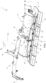
- the snow tiller 1 comprises a frame 2; two tiller modules 3 (one of which is not shown) supported by the frame 2 and substantially aligned in a transverse direction with respect to the longitudinal axis A1; a finisher 4 at the rear; and an adjusting assembly 5 for each tiller module 3.
- the frame 2 comprises a front hitch 6 configured to be connected to the drawbar (not shown in the attached figures); a support bar 7; two forks 8, each of which is configured to support a respective tiller module 3 and to enable small oscillations of the tiller module 3 around an axis parallel to the longitudinal axis A1.
- Each tiller module 3 is suspended from the respective fork 8, so that it can oscillate, and is hinged to the adjacent tiller module 3 so that the snow tiller 1 is able to adapt to the ground hollows transverse to the traveling direction D1.
- the frame 2 comprises a support 9 coupled to a respective fork 8 and configured to support the adjusting assembly 5.
- Each tiller module 3 comprises a motorised shaft 10, which rotates around a rotation axis A2 that extends in a direction substantially transversal to the longitudinal axis A1 and is equipped with a plurality of tools 11 configured to penetrate the snow cover; and a casing 12 arranged around the shaft 10 and configured to define a processing chamber 13 in which the snow is processed.
- the casing 12 also has a bearing function to support the shaft 10 and to connect the tiller module 3 to the frame 2.
- the finisher 4 comprises a flexible mat 14 coupled to the casing 12 to define the continuation of the casing 12; and a pressure bar 15 that extends in a direction transverse to the longitudinal axis A1 and is fixed above the flexible mat 14.
- the flexible mat 14 comprises a portion 16 that extends from the casing 12 to the pressure bar 15 and can be configured according to the distance between the pressure bar 15 and the casing 12.
- the pressure bar 15 is made up of sections 17, which are rigid and coupled to each other so as to enable small relative oscillations between adjacent sections 17 around axes substantially parallel to the longitudinal axis A1 and, thus, to adapt the pressure bar 15 and the flexible mat 14 to the irregularities and undulations of the snow cover transversely to the traveling direction D1.
- the sections 17 are made of metallic material, especially aluminium.
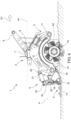
- the adjusting assembly 5 comprises a crossbar 18 that extends transversely to the longitudinal axis A1 directly above the pressure bar 15, and is coupled to the pressure bar 15 and to the support 9.
- crossbar 18 is connected to each section 17 of the pressure bar 15 by means of respective connecting elements 19.
- each connecting element 19 comprises an articulated head so as to enable small independent oscillations of each section 17 of the pressure bar 15 around a plurality of axes passing through the respective articulated head.
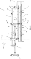
- the adjusting assembly 5 comprises a universal joint 20 to connect the crossbar 18 to the support 9, and a linear actuator 21, which is coupled to the frame 2 by means of a universal joint 22 and to the crossbar 18 by means of a universal joint 23.
- the linear actuator 21 is a hydraulic cylinder selectively controlled by force and in a position to adjust the distance between the pressure bar 15 and the casing 12.
- the snow tiller 1 comprises two adjusting assemblies 5, in which each linear actuator 21 is coupled to the respective fork 8 and in which each crossbar 18 is coupled to the respective support 9.
- a housing for the universal joint 20, which is a spherical joint, is located in the central portion of the body of the crossbar 18.
- the linear actuator 21 is a double-acting hydraulic cylinder the ends of which are coupled, respectively, to the frame 2 by means of a universal joint 22 and to the crossbar 18 by means of a universal joint 23.
- a central portion of the crossbar 18 comprises a seat for connecting to the linear actuator 21 by means of the universal joint 23, which comprises an articulated head.
- the adjusting assembly 5 enables the selective adjustment of the distance between the pressure bar 15 and the casing 12, by means of adjusting the length of the linear actuator 21.
- the adjustment of the distance between the pressure bar 15 and the casing 12 enables the configuration of the portion 16 of flexible mat 14, between the pressure bar 15 and the casing 12, to be adjusted, thus varying the amount of snow present in the processing chamber 13.
- the crossbar 18 rotates counter-clockwise around an axis passing through the universal joint 20 and parallel to the extension direction of the crossbar 18, causing the pressure rod 15 to approach the casing 12.
- the portion 16 of the flexible mat 14 is compressed and arches, defining a concavity towards the top.
- the length of the linear actuator 21 is manually controlled by the driver of the tracked vehicle by means of a special control interface arranged in the cab (not shown in the attached figures).
- the length of the linear actuator 21 is controlled automatically.
- the length of the linear actuator 21 is controlled according to some parameters detected by special sensors (not shown in the attached figures), preferably according to the properties of the snow cover, the height of the shaft 10 with respect to the snow cover, and the position of the shaft 10 with respect to the casing 12.
- the universal joint 20 which is a spherical joint, enables the crossbar 18 to oscillate, in a controlled manner, around an axis transverse to the longitudinal axis A1 and passing through the universal joint 20 in order to adjust the distance between the pressure bar 15 and the casing 12.
- the crossbar 18 also enables the crossbar 18 to oscillate freely around the universal joint 20 to adapt the pressure bar 15 and the flexible mat 14 to the transverse profile of the ski run, independently of the tiller module 3.
- the flexible mat 14 is able to remain in constant contact with the snow cover, even when the ski run has close variations in the transverse profile in the traveling direction D1.
- the adaptation of the pressure bar 15 to the snow cover conformation is also favoured by the connecting elements 19 comprising the articulated heads that make it possible for each section 17 to make small independent oscillations around a plurality of axes.
- a plane P on which the rotation axis A2 lies and passing through the universal joint 20 identifies a first spatial region above the plane P and a second spatial region below the plane P.
- the linear actuator 21 is arranged in the first spatial region, while the pressure bar 15 and the end of the flexible mat 14, which is connected to the casing 12, are arranged in the second spatial region.
- the amount of snow contained in the processing chamber 13 can be selectively adjusted so as to enable sufficient snow accumulation, when processing a snow cover, in order to level out irregularities in the snow cover or to avoid excessive amounts of tilled snow in the processing chamber 13 when not required.
Landscapes
- Engineering & Computer Science (AREA)
- Architecture (AREA)
- Civil Engineering (AREA)
- Structural Engineering (AREA)
- Soil Working Implements (AREA)
- Cleaning Of Streets, Tracks, Or Beaches (AREA)
- Structures Of Non-Positive Displacement Pumps (AREA)
- Control Of Transmission Device (AREA)
Claims (8)
- Schneefräse zur Präparierung einer Schneedecke von Skipisten, wobei die Schneefräse (1) konfiguriert ist, in einer Fahrtrichtung (D1) vorwärts bewegt zu werden, und umfasst:- einen Rahmen (2), der sich symmetrisch auf gegenüberliegenden bzw. entgegengesetzten Seiten einer Längsachse (A1) parallel zu der Fahrtrichtung (D1) erstreckt;- zumindest ein Fräsmodul (3), das mit dem Rahmen (2) gekoppelt ist und eine Welle (10), die sich um eine Drehachse (A2) quer zu der Längsachse (A1) dreht und mit einer Mehrzahl von Werkzeugen (11) ausgestattet ist, die konfiguriert sind, die Schneedecke zu durchdringen; und ein Gehäuse (12) umfasst, das um die Welle (10) herum angeordnet ist und eine Ver- bzw. Bearbeitungskammer begrenzt, in der der Schnee ver- bzw. bearbeitet wird;- einen Finisher (4), der eine flexible Matte (14), die konfiguriert ist, einen Stütz- bzw. Auflagebereich für die Schneefräse (1) auf der Schneedecke zu definieren und ein mit dem Gehäuse (12) gekoppeltes Ende umfasst; und eine Druckstange (15) umfasst, die sich quer zu der Längsachse (A1) erstreckt und an der flexiblen Matte (14) in einem Abstand von dem mit dem Gehäuse (12) gekoppelten Ende befestigt ist; und- zumindest eine Einstellanordnung bzw. -baugruppe (5), die mit der Druckstange (15) und dem Rahmen (2) und/oder Gehäuse (12) verbunden und konfiguriert ist, ein freies Schwingen der Druckstange (15) um eine Achse parallel zu der Längsachse (A1) der Schneefräse (1) zu ermöglichen und den Abstand zwischen der Druckstange (15) und dem Gehäuse (12) selektiv einzustellen, so dass der Abschnitt der flexiblen Matte (14) zwischen der Druckstange (15) und dem Gehäuse (12) eine Mehrzahl von Konfigurationen zwischen einer ausgefahrenen Konfiguration, die bei Neuschneebedingungen zu verwenden ist, und einer gewölbten Konfiguration mit einer nach oben gewandten Konkavität annehmen kann, um die Ansammlung von Schnee in der Verarbeitungskammer (13) zu erhöhen und Unebenheiten in der Schneedecke auszugleichen;wobei die zumindest eine Einstellanordnung (5) eine Querstange (18) umfasst, die sich quer zu der Längsachse (A1) erstreckt und mit der Druckstange (15) und, mittels eines Kugelgelenks (20), mit dem Rahmen (2) gekoppelt ist; wobei eine Ebene (P), auf der die Drehachse (A2) liegt und die durch das Kugelgelenk (20) verläuft, einen Raumbereich unter der Ebene (P) identifiziert; wobei die Druckstange (15) und das Ende der flexiblen Matte (14), das mit dem Gehäuse (12) gekoppelt ist, in diesem Raumbereich angeordnet sind.
- Schneefräse nach Anspruch 1, wobei die Einstellanordnung (5) konfiguriert ist, das Schwingen der Druckstange (15) um eine Achse quer zu der Längsachse (A1) selektiv zu steuern bzw. zu regeln, um den Abstand zwischen der Druckstange (15) und dem Gehäuse (12) einzustellen.
- Schneefräse nach Anspruch 1 oder 2, wobei die Einstellanordnung (5) einen Linearantrieb bzw. -aktuator (21) umfasst, der mittels eines ersten Universalgelenks (22) mit dem Rahmen (2) gekoppelt ist und mittels eines zweiten Universalgelenks (23) mit der Querstange (18) gekoppelt ist; wobei der Linearantrieb (21) konfiguriert ist, ein Schwingen der Querstange (18) um eine Achse zu steuern bzw. zu regeln, die durch das Kugelgelenk (20) verläuft und quer zu der Längsachse (A1) ist, um den Abstand zwischen der Druckstange (15) und dem Gehäuse (12) einzustellen.
- Schneefräse nach Anspruch 3, wobei das erste Universalgelenk (22) einen Gelenkkopf umfasst und/oder das zweite Universalgelenk (23) einen Gelenkkopf umfasst.
- Schneefräse nach einem der vorhergehenden Ansprüche, wobei die Druckstange (15) mit der Querstange (18) und der flexiblen Matte (14) gekoppelt ist, um eine im Wesentlichen translatorische Bewegung der Druckstange (15) entlang einer Richtung im Wesentlichen parallel zu der Längsachse (A1) zu ermöglichen.
- Schneefräse nach Anspruch 5, wobei die Druckstange (15) aus Sektionen (17) besteht, die starr und miteinander gekoppelt sind, um relative Schwingungen zwischen den Sektionen (17) in Bezug auf Achsen im Wesentlichen parallel zu der Längsachse (A1) zu ermöglichen; wobei die Querstange (18) mit jeder Sektion (17) durch ein Verbindungselement (19) verbunden ist, das wie ein Gelenkkopf geformt ist.
- Schneefräse nach einem der vorhergehenden Ansprüche, wobei die Querstange (18) mit der Druckstange (15) gekoppelt ist, so dass die Querstange (18) und die Druckstange (15) konfiguriert sind, fest um eine Achse zu schwingen, die durch das Kugelgelenk (20) verläuft und quer zu der Längsachse (A1) ist.
- Schneefräse nach einem der Ansprüche 3 bis 7, wobei der Linearantrieb (21) einen doppeltwirkenden, kraftgesteuerten bzw. -geregelten Hydraulikzylinder umfasst.
Applications Claiming Priority (2)
| Application Number | Priority Date | Filing Date | Title |
|---|---|---|---|
| IT102019000002017A IT201900002017A1 (it) | 2019-02-12 | 2019-02-12 | Fresa da neve per la preparazione di piste da sci |
| PCT/IB2020/051142 WO2020165799A1 (en) | 2019-02-12 | 2020-02-12 | A snow tiller for the preparation of ski runs |
Publications (3)
| Publication Number | Publication Date |
|---|---|
| EP3924552A1 EP3924552A1 (de) | 2021-12-22 |
| EP3924552C0 EP3924552C0 (de) | 2025-01-15 |
| EP3924552B1 true EP3924552B1 (de) | 2025-01-15 |
Family
ID=66476752
Family Applications (1)
| Application Number | Title | Priority Date | Filing Date |
|---|---|---|---|
| EP20705119.4A Active EP3924552B1 (de) | 2019-02-12 | 2020-02-12 | Schneefräse für die vorbereitung von skipisten |
Country Status (6)
| Country | Link |
|---|---|
| US (1) | US12221755B2 (de) |
| EP (1) | EP3924552B1 (de) |
| CN (1) | CN113728139A (de) |
| CA (1) | CA3129287A1 (de) |
| IT (1) | IT201900002017A1 (de) |
| WO (1) | WO2020165799A1 (de) |
Families Citing this family (3)
| Publication number | Priority date | Publication date | Assignee | Title |
|---|---|---|---|---|
| CN114250737A (zh) * | 2020-09-24 | 2022-03-29 | 普瑞诺斯股份公司 | 压雪车和控制压雪车的方法 |
| DE102022200466B4 (de) * | 2022-01-18 | 2024-08-01 | Kässbohrer Geländefahrzeug Aktiengesellschaft | Pistenraupe mit einem Fahrerhaus sowie mit einer Heckfräse und Heckfräse für eine Pistenraupe mit einem Fahrerhaus |
| DE102022208600A1 (de) * | 2022-08-18 | 2024-02-29 | Kässbohrer Geländefahrzeug Aktiengesellschaft | Heckfräse für eine Pistenraupe sowie Pistenraupe |
Citations (1)
| Publication number | Priority date | Publication date | Assignee | Title |
|---|---|---|---|---|
| DE4101617A1 (de) * | 1990-01-22 | 1991-07-25 | Bombardier Inc | Planiergeraet fuer schneeflaechen und verfahren zur aufbereitung und/oder pflege einer schneeflaeche |
Family Cites Families (12)
| Publication number | Priority date | Publication date | Assignee | Title |
|---|---|---|---|---|
| DE8536530U1 (de) * | 1985-12-24 | 1986-04-24 | Karl Kässbohrer Fahrzeugwerke GmbH, 7900 Ulm | Schneefräse |
| US4788783A (en) * | 1987-03-24 | 1988-12-06 | Bachler Anton R | Ski-track forming apparatus |
| US5067264A (en) * | 1987-04-21 | 1991-11-26 | Logan Manufacturing Company | Flexible rotary snow tiller |
| US4897941A (en) * | 1988-08-21 | 1990-02-06 | Logan Manufacturing Company | Snow grooming comb |
| DE9217472U1 (de) * | 1992-12-21 | 1993-02-25 | Karl Kässbohrer Fahrzeugwerke GmbH, 7900 Ulm | Pistenpflegevorrichtung |
| DE102006057272B4 (de) * | 2006-11-23 | 2011-11-10 | Kässbohrer Geländefahrzeug AG | Pistenpflegevorrichtung für ein Kraftfahrzeug, insbesondere ein Kettenfahrzeug |
| ITMI20070565A1 (it) * | 2007-03-21 | 2008-09-22 | Prinoth Spa | Fresa per la preparazione del manto nevoso delle piste da sci |
| ITMI20071783A1 (it) | 2007-09-14 | 2009-03-15 | Rolic Invest Sarl | Fresa rotante da neve per la preparazione del manto nevoso delle piste da sci |
| ITUA20162388A1 (it) * | 2016-04-07 | 2017-10-07 | Prinoth Spa | Apparato per realizzare una pista da sci di fondo |
| CN106884401B (zh) * | 2017-04-07 | 2018-07-03 | 广西玉林悍牛工程机器有限公司 | 压雪车雪犁刮板压实装置 |
| CN207582403U (zh) * | 2017-10-24 | 2018-07-06 | 北京宾度明德滑雪设备有限公司 | 一种雪道平整车 |
| IT201800003000A1 (it) * | 2018-02-23 | 2019-08-23 | Prinoth Spa | Fresa da neve e relativo metodo di regolazione |
-
2019
- 2019-02-12 IT IT102019000002017A patent/IT201900002017A1/it unknown
-
2020
- 2020-02-12 WO PCT/IB2020/051142 patent/WO2020165799A1/en not_active Ceased
- 2020-02-12 CN CN202080013454.6A patent/CN113728139A/zh active Pending
- 2020-02-12 CA CA3129287A patent/CA3129287A1/en active Pending
- 2020-02-12 EP EP20705119.4A patent/EP3924552B1/de active Active
- 2020-02-12 US US17/429,566 patent/US12221755B2/en active Active
Patent Citations (1)
| Publication number | Priority date | Publication date | Assignee | Title |
|---|---|---|---|---|
| DE4101617A1 (de) * | 1990-01-22 | 1991-07-25 | Bombardier Inc | Planiergeraet fuer schneeflaechen und verfahren zur aufbereitung und/oder pflege einer schneeflaeche |
Also Published As
| Publication number | Publication date |
|---|---|
| CA3129287A1 (en) | 2020-08-20 |
| US12221755B2 (en) | 2025-02-11 |
| WO2020165799A1 (en) | 2020-08-20 |
| EP3924552A1 (de) | 2021-12-22 |
| EP3924552C0 (de) | 2025-01-15 |
| IT201900002017A1 (it) | 2020-08-12 |
| US20220106750A1 (en) | 2022-04-07 |
| CN113728139A (zh) | 2021-11-30 |
Similar Documents
| Publication | Publication Date | Title |
|---|---|---|
| EP3924552B1 (de) | Schneefräse für die vorbereitung von skipisten | |
| US4651451A (en) | Lightweight snow compactor for ski runs | |
| RU2001109114A (ru) | Сельскохозяйственная уборочная машина | |
| US10119233B2 (en) | Plow assembly with cushioning attachment | |
| US10299421B2 (en) | Biasing system for harrows | |
| CA2956162C (en) | Tracked piste grooming vehicle for maintenance and shaping of snowy terrain | |
| KR20110099314A (ko) | 궤도 차량의 궤도 텐션 휠을 제어하기 위한 장치 | |
| CA2359861C (en) | Towed implement | |
| CN110184986B (zh) | 犁雪机及其调节方法 | |
| CA1101723A (en) | Transport wheel assembly for implements | |
| US6079193A (en) | Implement suspension with lost motion coupling | |
| US4487267A (en) | Agricultural apparatus with tool supported thereon and wheel adjustment structure therefor | |
| DK3085836T3 (en) | snowplow | |
| JP5217228B2 (ja) | クローラ型農用トラクタ | |
| EP2522779B1 (de) | Verbesserter Schneepflug zum Schneeräumen | |
| US8042873B2 (en) | Driver's seat of work vehicle | |
| KR20220022988A (ko) | 트랙터용 써레 | |
| EP2625943B1 (de) | Arbeitsgerät | |
| FI126587B (fi) | Alusaura ajoneuvoa varten | |
| JP3213251B2 (ja) | 刈取収穫機の刈取前処理装置支持構造 | |
| WO2001071098A1 (en) | Snow groomer with a variable snowchamber tiller assembly | |
| JP4126351B2 (ja) | コンバイン | |
| CA2403753A1 (en) | Snow groomer with a variable snowchamber tiller assembly | |
| SE469178B (sv) | Dragmekanism foer en straengspridare | |
| JPH11332355A (ja) | コンバイン |
Legal Events
| Date | Code | Title | Description |
|---|---|---|---|
| STAA | Information on the status of an ep patent application or granted ep patent |
Free format text: STATUS: UNKNOWN |
|
| STAA | Information on the status of an ep patent application or granted ep patent |
Free format text: STATUS: THE INTERNATIONAL PUBLICATION HAS BEEN MADE |
|
| PUAI | Public reference made under article 153(3) epc to a published international application that has entered the european phase |
Free format text: ORIGINAL CODE: 0009012 |
|
| STAA | Information on the status of an ep patent application or granted ep patent |
Free format text: STATUS: REQUEST FOR EXAMINATION WAS MADE |
|
| 17P | Request for examination filed |
Effective date: 20210823 |
|
| AK | Designated contracting states |
Kind code of ref document: A1 Designated state(s): AL AT BE BG CH CY CZ DE DK EE ES FI FR GB GR HR HU IE IS IT LI LT LU LV MC MK MT NL NO PL PT RO RS SE SI SK SM TR |
|
| DAV | Request for validation of the european patent (deleted) | ||
| DAX | Request for extension of the european patent (deleted) | ||
| P01 | Opt-out of the competence of the unified patent court (upc) registered |
Effective date: 20230518 |
|
| STAA | Information on the status of an ep patent application or granted ep patent |
Free format text: STATUS: EXAMINATION IS IN PROGRESS |
|
| 17Q | First examination report despatched |
Effective date: 20230908 |
|
| GRAP | Despatch of communication of intention to grant a patent |
Free format text: ORIGINAL CODE: EPIDOSNIGR1 |
|
| STAA | Information on the status of an ep patent application or granted ep patent |
Free format text: STATUS: GRANT OF PATENT IS INTENDED |
|
| INTG | Intention to grant announced |
Effective date: 20240816 |
|
| GRAS | Grant fee paid |
Free format text: ORIGINAL CODE: EPIDOSNIGR3 |
|
| GRAA | (expected) grant |
Free format text: ORIGINAL CODE: 0009210 |
|
| STAA | Information on the status of an ep patent application or granted ep patent |
Free format text: STATUS: THE PATENT HAS BEEN GRANTED |
|
| AK | Designated contracting states |
Kind code of ref document: B1 Designated state(s): AL AT BE BG CH CY CZ DE DK EE ES FI FR GB GR HR HU IE IS IT LI LT LU LV MC MK MT NL NO PL PT RO RS SE SI SK SM TR |
|
| REG | Reference to a national code |
Ref country code: CH Ref legal event code: EP Ref country code: GB Ref legal event code: FG4D |
|
| REG | Reference to a national code |
Ref country code: DE Ref legal event code: R096 Ref document number: 602020044759 Country of ref document: DE |
|
| REG | Reference to a national code |
Ref country code: IE Ref legal event code: FG4D |
|
| U01 | Request for unitary effect filed |
Effective date: 20250115 |
|
| U07 | Unitary effect registered |
Designated state(s): AT BE BG DE DK EE FI FR IT LT LU LV MT NL PT RO SE SI Effective date: 20250121 |
|
| P04 | Withdrawal of opt-out of the competence of the unified patent court (upc) registered |
Free format text: CASE NUMBER: APP_2818/2025 Effective date: 20250117 |
|
| U20 | Renewal fee for the european patent with unitary effect paid |
Year of fee payment: 6 Effective date: 20250212 |
|
| PG25 | Lapsed in a contracting state [announced via postgrant information from national office to epo] |
Ref country code: RS Free format text: LAPSE BECAUSE OF FAILURE TO SUBMIT A TRANSLATION OF THE DESCRIPTION OR TO PAY THE FEE WITHIN THE PRESCRIBED TIME-LIMIT Effective date: 20250415 |
|
| PG25 | Lapsed in a contracting state [announced via postgrant information from national office to epo] |
Ref country code: PL Free format text: LAPSE BECAUSE OF FAILURE TO SUBMIT A TRANSLATION OF THE DESCRIPTION OR TO PAY THE FEE WITHIN THE PRESCRIBED TIME-LIMIT Effective date: 20250115 |
|
| PG25 | Lapsed in a contracting state [announced via postgrant information from national office to epo] |
Ref country code: ES Free format text: LAPSE BECAUSE OF FAILURE TO SUBMIT A TRANSLATION OF THE DESCRIPTION OR TO PAY THE FEE WITHIN THE PRESCRIBED TIME-LIMIT Effective date: 20250115 |
|
| PG25 | Lapsed in a contracting state [announced via postgrant information from national office to epo] |
Ref country code: IS Free format text: LAPSE BECAUSE OF FAILURE TO SUBMIT A TRANSLATION OF THE DESCRIPTION OR TO PAY THE FEE WITHIN THE PRESCRIBED TIME-LIMIT Effective date: 20250515 Ref country code: NO Free format text: LAPSE BECAUSE OF FAILURE TO SUBMIT A TRANSLATION OF THE DESCRIPTION OR TO PAY THE FEE WITHIN THE PRESCRIBED TIME-LIMIT Effective date: 20250415 |
|
| PG25 | Lapsed in a contracting state [announced via postgrant information from national office to epo] |
Ref country code: HR Free format text: LAPSE BECAUSE OF FAILURE TO SUBMIT A TRANSLATION OF THE DESCRIPTION OR TO PAY THE FEE WITHIN THE PRESCRIBED TIME-LIMIT Effective date: 20250115 |
|
| PG25 | Lapsed in a contracting state [announced via postgrant information from national office to epo] |
Ref country code: GR Free format text: LAPSE BECAUSE OF FAILURE TO SUBMIT A TRANSLATION OF THE DESCRIPTION OR TO PAY THE FEE WITHIN THE PRESCRIBED TIME-LIMIT Effective date: 20250416 |
|
| PG25 | Lapsed in a contracting state [announced via postgrant information from national office to epo] |
Ref country code: SM Free format text: LAPSE BECAUSE OF FAILURE TO SUBMIT A TRANSLATION OF THE DESCRIPTION OR TO PAY THE FEE WITHIN THE PRESCRIBED TIME-LIMIT Effective date: 20250115 |
|
| PG25 | Lapsed in a contracting state [announced via postgrant information from national office to epo] |
Ref country code: MC Free format text: LAPSE BECAUSE OF FAILURE TO SUBMIT A TRANSLATION OF THE DESCRIPTION OR TO PAY THE FEE WITHIN THE PRESCRIBED TIME-LIMIT Effective date: 20250115 |
|
| PG25 | Lapsed in a contracting state [announced via postgrant information from national office to epo] |
Ref country code: CZ Free format text: LAPSE BECAUSE OF FAILURE TO SUBMIT A TRANSLATION OF THE DESCRIPTION OR TO PAY THE FEE WITHIN THE PRESCRIBED TIME-LIMIT Effective date: 20250115 |
|
| PG25 | Lapsed in a contracting state [announced via postgrant information from national office to epo] |
Ref country code: SK Free format text: LAPSE BECAUSE OF FAILURE TO SUBMIT A TRANSLATION OF THE DESCRIPTION OR TO PAY THE FEE WITHIN THE PRESCRIBED TIME-LIMIT Effective date: 20250115 |
|
| PLBE | No opposition filed within time limit |
Free format text: ORIGINAL CODE: 0009261 |
|
| STAA | Information on the status of an ep patent application or granted ep patent |
Free format text: STATUS: NO OPPOSITION FILED WITHIN TIME LIMIT |
|
| REG | Reference to a national code |
Ref country code: CH Ref legal event code: L10 Free format text: ST27 STATUS EVENT CODE: U-0-0-L10-L00 (AS PROVIDED BY THE NATIONAL OFFICE) Effective date: 20251126 |
|
| 26N | No opposition filed |
Effective date: 20251016 |
|
| GBPC | Gb: european patent ceased through non-payment of renewal fee |
Effective date: 20250415 |
|
| PG25 | Lapsed in a contracting state [announced via postgrant information from national office to epo] |
Ref country code: GB Free format text: LAPSE BECAUSE OF NON-PAYMENT OF DUE FEES Effective date: 20250415 |
|
| PG25 | Lapsed in a contracting state [announced via postgrant information from national office to epo] |
Ref country code: IE Free format text: LAPSE BECAUSE OF NON-PAYMENT OF DUE FEES Effective date: 20250212 |
|
| U20 | Renewal fee for the european patent with unitary effect paid |
Year of fee payment: 7 Effective date: 20260109 |
|
| REG | Reference to a national code |
Ref country code: CH Ref legal event code: U11 Free format text: ST27 STATUS EVENT CODE: U-0-0-U10-U11 (AS PROVIDED BY THE NATIONAL OFFICE) Effective date: 20260301 |
|
| PGFP | Annual fee paid to national office [announced via postgrant information from national office to epo] |
Ref country code: CH Payment date: 20260301 Year of fee payment: 7 |