EP3922372B1 - Maschine zum formen von rohrenden - Google Patents
Maschine zum formen von rohrenden Download PDFInfo
- Publication number
- EP3922372B1 EP3922372B1 EP21178633.0A EP21178633A EP3922372B1 EP 3922372 B1 EP3922372 B1 EP 3922372B1 EP 21178633 A EP21178633 A EP 21178633A EP 3922372 B1 EP3922372 B1 EP 3922372B1
- Authority
- EP
- European Patent Office
- Prior art keywords
- support body
- machine
- tool
- tools
- bearing table
- Prior art date
- Legal status (The legal status is an assumption and is not a legal conclusion. Google has not performed a legal analysis and makes no representation as to the accuracy of the status listed.)
- Active
Links
Images

Classifications
-
- B—PERFORMING OPERATIONS; TRANSPORTING
- B21—MECHANICAL METAL-WORKING WITHOUT ESSENTIALLY REMOVING MATERIAL; PUNCHING METAL
- B21D—WORKING OR PROCESSING OF SHEET METAL OR METAL TUBES, RODS OR PROFILES WITHOUT ESSENTIALLY REMOVING MATERIAL; PUNCHING METAL
- B21D19/00—Flanging or other edge treatment, e.g. of tubes
-
- B—PERFORMING OPERATIONS; TRANSPORTING
- B21—MECHANICAL METAL-WORKING WITHOUT ESSENTIALLY REMOVING MATERIAL; PUNCHING METAL
- B21D—WORKING OR PROCESSING OF SHEET METAL OR METAL TUBES, RODS OR PROFILES WITHOUT ESSENTIALLY REMOVING MATERIAL; PUNCHING METAL
- B21D41/00—Application of procedures in order to alter the diameter of tube ends
-
- B—PERFORMING OPERATIONS; TRANSPORTING
- B30—PRESSES
- B30B—PRESSES IN GENERAL
- B30B1/00—Presses, using a press ram, characterised by the features of the drive therefor, pressure being transmitted directly, or through simple thrust or tension members only, to the press ram or platen
- B30B1/26—Presses, using a press ram, characterised by the features of the drive therefor, pressure being transmitted directly, or through simple thrust or tension members only, to the press ram or platen by cams, eccentrics, or cranks
- B30B1/261—Presses, using a press ram, characterised by the features of the drive therefor, pressure being transmitted directly, or through simple thrust or tension members only, to the press ram or platen by cams, eccentrics, or cranks by cams
Definitions
- the present invention concerns a forming machine for ends of tubes, able to perform mechanical deformation operations on the ends of tubular elements, typically made of metal material.
- the forming machine for ends of tubes described here also called “end forming machine”
- the operations that can be carried out on the ends of the tubes with the machine described here can generally be shaping, rolling or butting.
- tubular elements hereafter also tubes, made of metal material require particular working of their end portions, for example to define shaped junction zones such as flanges, connections, attachments, characterized by widening and/or narrowing of the section with respect to the remaining portion of the tube, or other deformation operations.
- the support body can be configured either as a mobile slider on a vertical or horizontal plane, or as a table rotating on its central axis, to align the desired tool for the specific deformation operation with the end of the tube fixed on the vice, while the tools, or possibly even the entire support body in the case of a rotating table, are mobile forward/backward to engage the end portion of the tube on which to perform the working.
- Another purpose of the present invention is to provide a forming machine for the ends of metal tubular elements in which the impulsive stresses on the vice are reduced to a minimum.
- the tools are associated with the support body and have an adjustable working depth.
- the machine comprises at least one adjustment device attached to the support body, and which can be selectively associated with the tools in order to adjust their distance from the holding means in an adjustment direction parallel to the working direction.
- each tool comprises a working head always facing the holding means, and an opposite adjustment tang always facing the at least one adjustment device which is provided with a motorized head, wherein the adjustment tang of each tool and the motorized head are mobile with respect to each other so as to allow their reciprocal and temporary coupling.
- the support body comprises a slider sliding on guides parallel to each other and to the working direction and attached to the support frame, and a tool-bearing table on which the tools are mounted integrally, such tool-bearing table being mobile in rotation or translation with respect to the slider.
- the machine comprises a first motor member, able to drive and control the rotation or translation of the tool-bearing table, a second motor member, able to drive the adjustment device, and a command unit configured to coordinate at least the functioning of the first motor member and of the rotating motor member.
- the command unit is configured to coordinate the functioning of the motor members in such a way that when the support body is moved toward the inactive position, the first motor member drives the movement of the tool-bearing table in order to change the tool.
- the tools are mounted cantilevered on the tool-bearing table with respect to its thickness, which is defined in the working direction, the working heads and the adjustment tangs being disposed on opposite sides of the tool-bearing table.
- the uniform circular movement of the crank is characterized by a lower dead center, in correspondence with which the support body is in an inactive position away from the holding means, and by an upper dead center, in correspondence with which the support body is in an operative position close to the holding means.
- the machine comprises a support frame with which the holding means are associated, which are configured as a vice provided with a lower block and an upper block mobile one with respect to the other between a clamping position and a removed position.
- the drive means are attached to the support frame and to a rear portion of the support body in an opposite position with respect to the position in which the holding means are provided.
- the tool-bearing table has a cylindrical shape and is attached in a rotatable manner to a front portion of the tool-bearing table in order to align the development axis of a specific one of the tools with the axis of a tubular product being worked.
- the tool-bearing table has the shape of a parallelepiped and is attached in a translatable manner to a front portion of the tool-bearing table on guides that allow its movement along an exchange axis, transverse with respect to said working direction, in order to align the development axis of a specific one of the tools with the axis of a tubular product being worked.
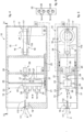
- the drive means 15 comprise a rotating motor member 32 able to supply a circular rotary movement with the same sense and operatively connected to a motion conversion device 16 configured to convert the circular rotary movement with the same sense into a linear alternating movement, alternately displacing the support body 13 in the working direction X.
- the motion conversion device 16 comprises actuation elements 17, 18 configured to convert the circular rotary movement with the same sense into linear alternating movement.
- the holding means 12 are configured as a vice 19 provided with a lower block and an upper block mobile with respect to each other between a clamping position and a removed position.
- each block is conformed in such a way that the vice 19 has one or more grooves with the shape of the at least one tubular element T to be clamped.
- the tubular element T is delimited along its development axis by ends 111, 112 and is disposed so that the end 112 facing the support body 13 is positioned cantilevered with respect to the vice 19 in order to allow its deformation.
- the length of the cantilevered end portion 112 depends on the specific working to be performed.
- the support body 13 comprises a slider 20 sliding on guides 21 parallel to each other and to the working axis X and attached to the support frame 11, and a tool-bearing table 22 on which the tools 14 are mounted integrally.
- the tools 14 are disposed in such a way that their development axis is parallel to the axis of the tubular element T clamped in the vice 19, in particular at least parallel to the development axis of the end portion 112.
- the tools 14 can comprise punches, rolling devices, chip removal tools, devices for making a thread or suchlike.
- the slider 20 can have lateral walls, which cooperate in a sliding manner with the guides 21, and transverse walls having a stiffening and supporting function.
- the machine 10 comprises a first motor member 30 able to drive and control the rotation or translation of the tool-bearing table 22 according to the specific working cycle. If the tool-bearing table 22 has a circular shape, the first motor member 30 is able to activate and control its rotation, while if the tool-bearing table 22 has the shape of a parallelepiped, the first motor member 30 drives and controls its translation along the exchange axis Y.
- the guides 25 can be disposed horizontally, for example parallel to each other and with respect to the support plane where the machine 10 is installed.
- the machine 10 comprises at least one adjustment device 28 which can be selectively associated with the adjustment tangs 27 of the tools 14 so as to adjust the distance of the working heads 26 from the holding means 12, according to the specific family of tubular elements T to be worked, along an adjustment axis, or direction, Z parallel to the working axis X.
- the adjustment axis Z coincides with the working axis X, but, depending on requirements, this does not always have to be the case.
- the motion conversion device 16 can be selected from a group comprising a connecting rod-crank mechanism, an eccentric mechanism, an oscillating yoke, a cam mechanism or other mechanisms that have the characteristics expressed in claim 1.
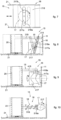
- the uniform circular movement of the crank 117 is characterized by a lower dead center, in correspondence with which the support body 13 is in the inactive position away from the holding means, and by an upper dead center, in correspondence with which the support body 13 is in the operative position close to the holding means (indicated by a dashed line in figs. 1-2 and figs. 4-5 ).
- the conversion device 16 comprises a first actuation element 17 configured as a cam 517 and a second actuation element 18 configured as a transmission rod 518 provided at a first end with a plate 518a cooperating with the cam 517.
- the transmission rod 518 is associated, with respect to an opposite second end, with the slider 20 of the support body 13.
Landscapes
- Engineering & Computer Science (AREA)
- Mechanical Engineering (AREA)
- Bending Of Plates, Rods, And Pipes (AREA)
- Shaping Metal By Deep-Drawing, Or The Like (AREA)
Claims (12)
- Formmaschine (10) für Enden von metallischen Rohrelementen (T), wobei die genannte Maschine (10) umfasst:- Mittel (12) zum Halten der genannten Rohrelemente (T),- einen Stützkörper (13) zum Stützen einer Vielzahl von Werkzeugen (14) zum Formen von Enden (111, 112) der genannten Rohrelemente (T), die selektiv mit dem genannten zumindest einen Rohrelement (T) in einer Arbeitsrichtung (X) ausgerichtet werden können, wobei die genannten Werkzeuge (14) mit dem genannten Stützkörper (13) verbunden sind und eine einstellbare Arbeitstiefe aufweisen,
worin der genannte Stützkörper (13) einen Schieber (20), der auf Führungen (21) gleitet, die zueinander und zur Arbeitsrichtung (X) parallel sind und die am Stützrahmen (11) befestigt sind, und einen Werkzeughaltetisch (22) umfasst, an dem die Werkzeuge (14) einstückig montiert sind, wobei der genannte Werkzeughaltetisch (22) im Hinblick auf den genannten Schieber (20) dreh- oder verschiebebeweglich ist;- Mittel (15) zum Antreiben des genannten Stützkörpers (13), um ihn in der genannten Arbeitsrichtung (X) zu den/weg von den genannten Haltemitteln (12) zu bewegen,dadurch gekennzeichnet, dass die genannte Maschine (10) zumindest eine Einstellungseinrichtung (28) umfasst, die am genannten Stützkörper (13) befestigt ist und die mit den genannten Werkzeugen (14) selektiv verbunden werden kann, um ihren Abstand von den genannten Haltemitteln (12) in einer Einstellungsrichtung (Z) einzustellen, die parallel zur genannten Arbeitsrichtung (X) ist, wobei jedes Werkzeug (14) einen Arbeitskopf (26), der immer den genannten Haltemitteln (12) zugewandt ist, und einen gegenüberliegenden Einstellungsschaft (27), der immer der genannten zumindest einen Einstellungseinrichtung (28) zugewandt ist, die mit einem motorbetriebenen Kopf (29) versehen ist, umfasst, wobei der genannte Einstellungsschaft (27) jedes Werkzeugs (14) und der motorbetriebene Kopf (29) zueinander beweglich sind, um ihre gegenseitige und zeitweilige Kupplung zu ermöglichen.worin die genannten Antriebsmittel (15) ein Drehmotorelement (32) umfassen, das in der Lage ist, eine kreisförmige Drehbewegung in demselben Sinne zu liefern, und mit einer Bewegungsumwandlungsvorrichtung (16) wirkmäßig verbunden ist, die dafür ausgelegt ist, die genannte kreisförmige Drehbewegung in demselben Sinne in eine lineare alternierende Bewegung umzuwandeln, indem der genannte Stützkörper (13) in der Arbeitsrichtung (X) abwechselnd verfahren wird,worin die genannte Bewegungsumwandlungsvorrichtung (16) einen Verbindungsstange-Kurbel-Mechanismus umfasst, in dem ein erstes Betätigungselement (17) als Kurbel (117) ausgestaltet ist, die sich um eine Achse dreht, die zur genannten Arbeitsrichtung (X) orthogonal ist, und in dem ein zweites Betätigungselement (18) als Verbindungsstange (118) ausgestaltet ist, die an einer Seite an der genannten Kurbel (117) und an der gegenüberliegenden Seite am Hinterteil des genannten Stützkörpers (13) schwenkbar gelagert ist; - Maschine (10) nach Anspruch 1, dadurch gekennzeichnet, dass die genannten Werkzeuge (14) mit dem genannten Stützkörper (13) einstückig sind und auf eine voreinstellbare Arbeitstiefe eingestellt sind.
- Maschine (10) nach Anspruch oder 2, dadurch gekennzeichnet, dass die genannten Werkzeuge (14) mit dem genannten Stützkörper (13) verbunden sind, um eine Arbeitstiefe zu haben, die ohne Vorbereitung eingestellt werden kann.
- Maschine (10) nach Anspruch 1, 2 oder 3, dadurch gekennzeichnet, dass die genannte Maschine (10) ein erstes Motorelement (30), das die Drehung oder die Verschiebung des genannten Werkzeughaltetisches (22) antreiben und steuern kann, ein zweites Motorelement (31), das die Einstellungseinrichtung (28) antreiben kann, und eine Bedienungseinheit (33) umfasst, die dafür ausgelegt ist, zumindest das Funktionieren des genannten ersten Motorelementes (30) und des genannten Drehmotorelementes (32) zu koordinieren.
- Maschine (10) nach Anspruch 4, dadurch gekennzeichnet, dass die genannte Bedienungseinheit (33) dafür ausgelegt ist, das Funktionieren der genannten Motorelemente (30, 32) so zu koordinieren, dass, wenn der genannte Stützkörper (13) zu einer inaktiven Stellung bewegt wird, das genannte erste Motorelement (30) die Bewegung des genannten Werkzeughaltetisches (22) antreibt, um das Werkzeug (14) zu wechseln.
- Maschine (10) nach Anspruch 4 oder 5, dadurch gekennzeichnet, dass die genannten Motorelemente (30, 31, 32) als Induktionslinearmotore, Synchronlinearmotore, bürstenlose Synchronlinearmotore, homopolare Linearmotore, Schwingspulen-Linearmotore oder Rohrlinearmotore ausgestaltet sind.
- Maschine (10) nach einem der vorhergehenden Ansprüche, dadurch gekennzeichnet, dass die genannten Werkzeuge (14) am genannten Werkzeughaltetisch (22) im Hinblick auf seine Dicke, die in der genannten Arbeitsrichtung (X) definiert ist, freitragend montiert sind, wobei die genannten Arbeitsköpfe (26) und die genannten Einstellungsschäfte (27) an gegenüberliegenden Seiten des genannten Werkzeughaltetisches (22) angeordnet sind.
- Maschine (10) nach einem der vorhergehenden Ansprüche, dadurch gekennzeichnet, dass die gleichmäßige kreisförmige Bewegung der genannten Kurbel (117) durch einen unteren Totpunkt, an welchem der genannte Stützkörper (13) sich in einer inaktiven Stellung weg von den genannten Haltemitteln (12) befindet, und durch einen oberen Totpunkt, an welchem der genannte Stützkörper (13) sich in einer betriebsfähigen Stellung nahe bei den genannten Haltemitteln (12) befindet, gekennzeichnet ist.
- Maschine (10) nach einem der vorhergehenden Ansprüche, dadurch gekennzeichnet, dass sie einen Stützrahmen (11) umfasst, mit dem die genannten Haltemittel (12) verbunden sind, die als Spannstock (19) ausgestaltet sind, der mit einem unteren Block und einem oberen Block versehen ist, die zueinander zwischen einer Spannstellung und einer Ausziehstellung beweglich sind.
- Maschine (10) nach einem der vorhergehenden Ansprüche, dadurch gekennzeichnet, dass die genannten Antriebsmittel (15) am genannten Stützrahmen (11) und an einem Hinterabschnitt (24) des genannten Stützkörpers (13) in einer gegenüberliegenden Stellung im Hinblick auf die Stellung, in der die genannten Haltemittel (12) vorgesehen sind, befestigt sind.
- Maschine (10) nach einem der vorhergehenden Ansprüche, dadurch gekennzeichnet, dass der genannte Werkzeughaltetisch (22) eine zylindrische Form hat und in einer drehbaren Weise an einem Vorderabschnitt (23) des genannten Werkzeughaltetisches (22) befestigt ist, um die Verlaufsachse eines spezifischen von den genannten Werkzeugen (14) zu der Achse eines rohrförmigen Produktes (T), das gerade bearbeitet wird, auszurichten.
- Maschine (10) nach einem der Ansprüche 1 bis 10, dadurch gekennzeichnet, dass der genannte Werkzeughaltetisch (22) die Form eines Parallelepipeds hat und in einer verfahrbaren Weise an einem Vorderabschnitt (23) des genannten Werkzeughaltetisches (22) auf Führungen (25) befestigt ist, die seine Bewegung entlang einer Wechselachse (Y), quer zur genannten Arbeitsrichtung (X), ermöglichen, um die Verlaufsachse eines spezifischen von den genannten Werkzeugen (14) zu der Achse eines rohrförmigen Produktes (T), das gerade bearbeitet wird, auszurichten.
Applications Claiming Priority (1)
| Application Number | Priority Date | Filing Date | Title |
|---|---|---|---|
| IT202000013672 | 2020-06-09 |
Publications (3)
| Publication Number | Publication Date |
|---|---|
| EP3922372A1 EP3922372A1 (de) | 2021-12-15 |
| EP3922372B1 true EP3922372B1 (de) | 2024-07-03 |
| EP3922372C0 EP3922372C0 (de) | 2024-07-03 |
Family
ID=72266689
Family Applications (1)
| Application Number | Title | Priority Date | Filing Date |
|---|---|---|---|
| EP21178633.0A Active EP3922372B1 (de) | 2020-06-09 | 2021-06-09 | Maschine zum formen von rohrenden |
Country Status (1)
| Country | Link |
|---|---|
| EP (1) | EP3922372B1 (de) |
Families Citing this family (1)
| Publication number | Priority date | Publication date | Assignee | Title |
|---|---|---|---|---|
| CN115138741B (zh) * | 2022-08-16 | 2025-01-28 | 山东奥扬新能源科技股份有限公司 | 一种金属杆冲压装置 |
Family Cites Families (5)
| Publication number | Priority date | Publication date | Assignee | Title |
|---|---|---|---|---|
| US3696657A (en) | 1970-11-19 | 1972-10-10 | Coors Porcelain Co | Metal working crank and slide press mechanism |
| EP2123373A4 (de) | 2007-03-09 | 2015-10-14 | Mitsubishi Materials Corp | Dosenherstellungsvorrichtung und dosenherstellungsverfahren |
| FR2921003B1 (fr) | 2007-09-17 | 2009-12-18 | Silfax Group | Machine electrique pour la deformation des extremites d'un profil. |
| ES2398642T3 (es) | 2010-03-05 | 2013-03-20 | Hinterkopf Gmbh | Dispositivo de conformado |
| CN102688922A (zh) | 2012-06-25 | 2012-09-26 | 王俊强 | 管件端部成型机 |
-
2021
- 2021-06-09 EP EP21178633.0A patent/EP3922372B1/de active Active
Also Published As
| Publication number | Publication date |
|---|---|
| EP3922372C0 (de) | 2024-07-03 |
| EP3922372A1 (de) | 2021-12-15 |
Similar Documents
| Publication | Publication Date | Title |
|---|---|---|
| JPS6229157Y2 (de) | ||
| US7004006B2 (en) | Motor driven link press | |
| KR101528584B1 (ko) | 바아형 부재 지지장치 및 이를 이용한 바아형 부재 가공용 레이저 가공기 | |
| CN107591976B (zh) | 四头内绕绕线机 | |
| US3245433A (en) | Wire bending machine | |
| US4753099A (en) | Bending press for sheet metal | |
| CN108380715B (zh) | 一种弯管机 | |
| EP3922372A1 (de) | Maschine zum formen von rohrenden | |
| CN114871818B (zh) | 一种机床换刀装置、机床以及机床换刀方法 | |
| CN209829942U (zh) | 一种弯管机 | |
| CN220781890U (zh) | 一种全自动u形弯管机 | |
| US4462741A (en) | Pressing machine with a built-in robot | |
| US6295857B1 (en) | Method and machine for automatically bending profiled elements and the like | |
| KR20120002876A (ko) | 고정자의 권선 장치 | |
| JP2008161922A (ja) | フィン付き蛇行チューブの多段重ね曲げ加工方法およびその装置 | |
| CN203913194U (zh) | 全自动锯骨机退刀机构 | |
| CN216528415U (zh) | 一种自动化磁环绕线机 | |
| CN221454172U (zh) | 数控钢筋折弯机 | |
| CN213763540U (zh) | 一种钣金折弯中心 | |
| JPH01192436A (ja) | 空気圧又は油圧駆動されるクランク装置を備えた挟持送り装置 | |
| CN210208202U (zh) | 一种双弯弯管机 | |
| CN218855270U (zh) | 新型折弯机 | |
| CN210253694U (zh) | 一种自动折弯机 | |
| CN215918738U (zh) | 一种电容器用散热机构的铜管扩折弯装置 | |
| CN213183751U (zh) | 一种全自动数控母线折弯机的折弯机构 |
Legal Events
| Date | Code | Title | Description |
|---|---|---|---|
| PUAI | Public reference made under article 153(3) epc to a published international application that has entered the european phase |
Free format text: ORIGINAL CODE: 0009012 |
|
| STAA | Information on the status of an ep patent application or granted ep patent |
Free format text: STATUS: THE APPLICATION HAS BEEN PUBLISHED |
|
| AK | Designated contracting states |
Kind code of ref document: A1 Designated state(s): AL AT BE BG CH CY CZ DE DK EE ES FI FR GB GR HR HU IE IS IT LI LT LU LV MC MK MT NL NO PL PT RO RS SE SI SK SM TR |
|
| B565 | Issuance of search results under rule 164(2) epc |
Effective date: 20211026 |
|
| STAA | Information on the status of an ep patent application or granted ep patent |
Free format text: STATUS: REQUEST FOR EXAMINATION WAS MADE |
|
| 17P | Request for examination filed |
Effective date: 20220615 |
|
| RBV | Designated contracting states (corrected) |
Designated state(s): AL AT BE BG CH CY CZ DE DK EE ES FI FR GB GR HR HU IE IS IT LI LT LU LV MC MK MT NL NO PL PT RO RS SE SI SK SM TR |
|
| GRAP | Despatch of communication of intention to grant a patent |
Free format text: ORIGINAL CODE: EPIDOSNIGR1 |
|
| STAA | Information on the status of an ep patent application or granted ep patent |
Free format text: STATUS: GRANT OF PATENT IS INTENDED |
|
| INTG | Intention to grant announced |
Effective date: 20240131 |
|
| GRAS | Grant fee paid |
Free format text: ORIGINAL CODE: EPIDOSNIGR3 |
|
| GRAA | (expected) grant |
Free format text: ORIGINAL CODE: 0009210 |
|
| STAA | Information on the status of an ep patent application or granted ep patent |
Free format text: STATUS: THE PATENT HAS BEEN GRANTED |
|
| AK | Designated contracting states |
Kind code of ref document: B1 Designated state(s): AL AT BE BG CH CY CZ DE DK EE ES FI FR GB GR HR HU IE IS IT LI LT LU LV MC MK MT NL NO PL PT RO RS SE SI SK SM TR |
|
| REG | Reference to a national code |
Ref country code: CH Ref legal event code: EP |
|
| REG | Reference to a national code |
Ref country code: DE Ref legal event code: R096 Ref document number: 602021015035 Country of ref document: DE |
|
| U01 | Request for unitary effect filed |
Effective date: 20240729 |
|
| U07 | Unitary effect registered |
Designated state(s): AT BE BG DE DK EE FI FR IT LT LU LV MT NL PT RO SE SI Effective date: 20240902 |
|
| PG25 | Lapsed in a contracting state [announced via postgrant information from national office to epo] |
Ref country code: NO Free format text: LAPSE BECAUSE OF FAILURE TO SUBMIT A TRANSLATION OF THE DESCRIPTION OR TO PAY THE FEE WITHIN THE PRESCRIBED TIME-LIMIT Effective date: 20241003 |
|
| PG25 | Lapsed in a contracting state [announced via postgrant information from national office to epo] |
Ref country code: GR Free format text: LAPSE BECAUSE OF FAILURE TO SUBMIT A TRANSLATION OF THE DESCRIPTION OR TO PAY THE FEE WITHIN THE PRESCRIBED TIME-LIMIT Effective date: 20241004 Ref country code: PL Free format text: LAPSE BECAUSE OF FAILURE TO SUBMIT A TRANSLATION OF THE DESCRIPTION OR TO PAY THE FEE WITHIN THE PRESCRIBED TIME-LIMIT Effective date: 20240703 |
|
| PG25 | Lapsed in a contracting state [announced via postgrant information from national office to epo] |
Ref country code: IS Free format text: LAPSE BECAUSE OF FAILURE TO SUBMIT A TRANSLATION OF THE DESCRIPTION OR TO PAY THE FEE WITHIN THE PRESCRIBED TIME-LIMIT Effective date: 20241103 |
|
| PG25 | Lapsed in a contracting state [announced via postgrant information from national office to epo] |
Ref country code: HR Free format text: LAPSE BECAUSE OF FAILURE TO SUBMIT A TRANSLATION OF THE DESCRIPTION OR TO PAY THE FEE WITHIN THE PRESCRIBED TIME-LIMIT Effective date: 20240703 Ref country code: CZ Free format text: LAPSE BECAUSE OF FAILURE TO SUBMIT A TRANSLATION OF THE DESCRIPTION OR TO PAY THE FEE WITHIN THE PRESCRIBED TIME-LIMIT Effective date: 20240703 |
|
| PG25 | Lapsed in a contracting state [announced via postgrant information from national office to epo] |
Ref country code: ES Free format text: LAPSE BECAUSE OF FAILURE TO SUBMIT A TRANSLATION OF THE DESCRIPTION OR TO PAY THE FEE WITHIN THE PRESCRIBED TIME-LIMIT Effective date: 20240703 Ref country code: RS Free format text: LAPSE BECAUSE OF FAILURE TO SUBMIT A TRANSLATION OF THE DESCRIPTION OR TO PAY THE FEE WITHIN THE PRESCRIBED TIME-LIMIT Effective date: 20241003 |
|
| PG25 | Lapsed in a contracting state [announced via postgrant information from national office to epo] |
Ref country code: RS Free format text: LAPSE BECAUSE OF FAILURE TO SUBMIT A TRANSLATION OF THE DESCRIPTION OR TO PAY THE FEE WITHIN THE PRESCRIBED TIME-LIMIT Effective date: 20241003 Ref country code: PL Free format text: LAPSE BECAUSE OF FAILURE TO SUBMIT A TRANSLATION OF THE DESCRIPTION OR TO PAY THE FEE WITHIN THE PRESCRIBED TIME-LIMIT Effective date: 20240703 Ref country code: NO Free format text: LAPSE BECAUSE OF FAILURE TO SUBMIT A TRANSLATION OF THE DESCRIPTION OR TO PAY THE FEE WITHIN THE PRESCRIBED TIME-LIMIT Effective date: 20241003 Ref country code: IS Free format text: LAPSE BECAUSE OF FAILURE TO SUBMIT A TRANSLATION OF THE DESCRIPTION OR TO PAY THE FEE WITHIN THE PRESCRIBED TIME-LIMIT Effective date: 20241103 Ref country code: HR Free format text: LAPSE BECAUSE OF FAILURE TO SUBMIT A TRANSLATION OF THE DESCRIPTION OR TO PAY THE FEE WITHIN THE PRESCRIBED TIME-LIMIT Effective date: 20240703 Ref country code: GR Free format text: LAPSE BECAUSE OF FAILURE TO SUBMIT A TRANSLATION OF THE DESCRIPTION OR TO PAY THE FEE WITHIN THE PRESCRIBED TIME-LIMIT Effective date: 20241004 Ref country code: ES Free format text: LAPSE BECAUSE OF FAILURE TO SUBMIT A TRANSLATION OF THE DESCRIPTION OR TO PAY THE FEE WITHIN THE PRESCRIBED TIME-LIMIT Effective date: 20240703 Ref country code: CZ Free format text: LAPSE BECAUSE OF FAILURE TO SUBMIT A TRANSLATION OF THE DESCRIPTION OR TO PAY THE FEE WITHIN THE PRESCRIBED TIME-LIMIT Effective date: 20240703 |
|
| PG25 | Lapsed in a contracting state [announced via postgrant information from national office to epo] |
Ref country code: SM Free format text: LAPSE BECAUSE OF FAILURE TO SUBMIT A TRANSLATION OF THE DESCRIPTION OR TO PAY THE FEE WITHIN THE PRESCRIBED TIME-LIMIT Effective date: 20240703 |
|
| PG25 | Lapsed in a contracting state [announced via postgrant information from national office to epo] |
Ref country code: SK Free format text: LAPSE BECAUSE OF FAILURE TO SUBMIT A TRANSLATION OF THE DESCRIPTION OR TO PAY THE FEE WITHIN THE PRESCRIBED TIME-LIMIT Effective date: 20240703 |
|
| PLBE | No opposition filed within time limit |
Free format text: ORIGINAL CODE: 0009261 |
|
| STAA | Information on the status of an ep patent application or granted ep patent |
Free format text: STATUS: NO OPPOSITION FILED WITHIN TIME LIMIT |
|
| U20 | Renewal fee for the european patent with unitary effect paid |
Year of fee payment: 5 Effective date: 20250418 |
|
| 26N | No opposition filed |
Effective date: 20250404 |
|
| REG | Reference to a national code |
Ref country code: CH Ref legal event code: H13 Free format text: ST27 STATUS EVENT CODE: U-0-0-H10-H13 (AS PROVIDED BY THE NATIONAL OFFICE) Effective date: 20260127 |
|
| PG25 | Lapsed in a contracting state [announced via postgrant information from national office to epo] |
Ref country code: MC Free format text: LAPSE BECAUSE OF FAILURE TO SUBMIT A TRANSLATION OF THE DESCRIPTION OR TO PAY THE FEE WITHIN THE PRESCRIBED TIME-LIMIT Effective date: 20240703 |
|
| GBPC | Gb: european patent ceased through non-payment of renewal fee |
Effective date: 20250609 |
|
| PG25 | Lapsed in a contracting state [announced via postgrant information from national office to epo] |
Ref country code: GB Free format text: LAPSE BECAUSE OF NON-PAYMENT OF DUE FEES Effective date: 20250609 |
|
| PG25 | Lapsed in a contracting state [announced via postgrant information from national office to epo] |
Ref country code: IE Free format text: LAPSE BECAUSE OF NON-PAYMENT OF DUE FEES Effective date: 20250609 |
|
| PG25 | Lapsed in a contracting state [announced via postgrant information from national office to epo] |
Ref country code: CH Free format text: LAPSE BECAUSE OF NON-PAYMENT OF DUE FEES Effective date: 20250630 |