EP3920214B1 - Heat-dissipating member and manufacturing method for same - Google Patents
Heat-dissipating member and manufacturing method for same Download PDFInfo
- Publication number
- EP3920214B1 EP3920214B1 EP20747772.0A EP20747772A EP3920214B1 EP 3920214 B1 EP3920214 B1 EP 3920214B1 EP 20747772 A EP20747772 A EP 20747772A EP 3920214 B1 EP3920214 B1 EP 3920214B1
- Authority
- EP
- European Patent Office
- Prior art keywords
- heat dissipation
- dissipation member
- represented
- main surface
- curve
- Prior art date
- Legal status (The legal status is an assumption and is not a legal conclusion. Google has not performed a legal analysis and makes no representation as to the accuracy of the status listed.)
- Active
Links
Images
Classifications
-
- H—ELECTRICITY
- H05—ELECTRIC TECHNIQUES NOT OTHERWISE PROVIDED FOR
- H05K—PRINTED CIRCUITS; CASINGS OR CONSTRUCTIONAL DETAILS OF ELECTRIC APPARATUS; MANUFACTURE OF ASSEMBLAGES OF ELECTRICAL COMPONENTS
- H05K7/00—Constructional details common to different types of electric apparatus
- H05K7/20—Modifications to facilitate cooling, ventilating, or heating
- H05K7/2039—Modifications to facilitate cooling, ventilating, or heating characterised by the heat transfer by conduction from the heat generating element to a dissipating body
-
- H—ELECTRICITY
- H01—ELECTRIC ELEMENTS
- H01L—SEMICONDUCTOR DEVICES NOT COVERED BY CLASS H10
- H01L23/00—Details of semiconductor or other solid state devices
- H01L23/34—Arrangements for cooling, heating, ventilating or temperature compensation ; Temperature sensing arrangements
- H01L23/36—Selection of materials, or shaping, to facilitate cooling or heating, e.g. heatsinks
- H01L23/373—Cooling facilitated by selection of materials for the device or materials for thermal expansion adaptation, e.g. carbon
- H01L23/3736—Metallic materials
-
- B—PERFORMING OPERATIONS; TRANSPORTING
- B28—WORKING CEMENT, CLAY, OR STONE
- B28B—SHAPING CLAY OR OTHER CERAMIC COMPOSITIONS; SHAPING SLAG; SHAPING MIXTURES CONTAINING CEMENTITIOUS MATERIAL, e.g. PLASTER
- B28B3/00—Producing shaped articles from the material by using presses; Presses specially adapted therefor
- B28B3/02—Producing shaped articles from the material by using presses; Presses specially adapted therefor wherein a ram exerts pressure on the material in a moulding space; Ram heads of special form
- B28B3/025—Hot pressing, e.g. of ceramic materials
-
- C—CHEMISTRY; METALLURGY
- C04—CEMENTS; CONCRETE; ARTIFICIAL STONE; CERAMICS; REFRACTORIES
- C04B—LIME, MAGNESIA; SLAG; CEMENTS; COMPOSITIONS THEREOF, e.g. MORTARS, CONCRETE OR LIKE BUILDING MATERIALS; ARTIFICIAL STONE; CERAMICS; REFRACTORIES; TREATMENT OF NATURAL STONE
- C04B35/00—Shaped ceramic products characterised by their composition; Ceramics compositions; Processing powders of inorganic compounds preparatory to the manufacturing of ceramic products
- C04B35/515—Shaped ceramic products characterised by their composition; Ceramics compositions; Processing powders of inorganic compounds preparatory to the manufacturing of ceramic products based on non-oxide ceramics
- C04B35/56—Shaped ceramic products characterised by their composition; Ceramics compositions; Processing powders of inorganic compounds preparatory to the manufacturing of ceramic products based on non-oxide ceramics based on carbides or oxycarbides
- C04B35/565—Shaped ceramic products characterised by their composition; Ceramics compositions; Processing powders of inorganic compounds preparatory to the manufacturing of ceramic products based on non-oxide ceramics based on carbides or oxycarbides based on silicon carbide
- C04B35/575—Shaped ceramic products characterised by their composition; Ceramics compositions; Processing powders of inorganic compounds preparatory to the manufacturing of ceramic products based on non-oxide ceramics based on carbides or oxycarbides based on silicon carbide obtained by pressure sintering
-
- C—CHEMISTRY; METALLURGY
- C04—CEMENTS; CONCRETE; ARTIFICIAL STONE; CERAMICS; REFRACTORIES
- C04B—LIME, MAGNESIA; SLAG; CEMENTS; COMPOSITIONS THEREOF, e.g. MORTARS, CONCRETE OR LIKE BUILDING MATERIALS; ARTIFICIAL STONE; CERAMICS; REFRACTORIES; TREATMENT OF NATURAL STONE
- C04B41/00—After-treatment of mortars, concrete, artificial stone or ceramics; Treatment of natural stone
- C04B41/009—After-treatment of mortars, concrete, artificial stone or ceramics; Treatment of natural stone characterised by the material treated
-
- C—CHEMISTRY; METALLURGY
- C04—CEMENTS; CONCRETE; ARTIFICIAL STONE; CERAMICS; REFRACTORIES
- C04B—LIME, MAGNESIA; SLAG; CEMENTS; COMPOSITIONS THEREOF, e.g. MORTARS, CONCRETE OR LIKE BUILDING MATERIALS; ARTIFICIAL STONE; CERAMICS; REFRACTORIES; TREATMENT OF NATURAL STONE
- C04B41/00—After-treatment of mortars, concrete, artificial stone or ceramics; Treatment of natural stone
- C04B41/45—Coating or impregnating, e.g. injection in masonry, partial coating of green or fired ceramics, organic coating compositions for adhering together two concrete elements
- C04B41/4505—Coating or impregnating, e.g. injection in masonry, partial coating of green or fired ceramics, organic coating compositions for adhering together two concrete elements characterised by the method of application
- C04B41/4523—Coating or impregnating, e.g. injection in masonry, partial coating of green or fired ceramics, organic coating compositions for adhering together two concrete elements characterised by the method of application applied from the molten state ; Thermal spraying, e.g. plasma spraying
-
- C—CHEMISTRY; METALLURGY
- C04—CEMENTS; CONCRETE; ARTIFICIAL STONE; CERAMICS; REFRACTORIES
- C04B—LIME, MAGNESIA; SLAG; CEMENTS; COMPOSITIONS THEREOF, e.g. MORTARS, CONCRETE OR LIKE BUILDING MATERIALS; ARTIFICIAL STONE; CERAMICS; REFRACTORIES; TREATMENT OF NATURAL STONE
- C04B41/00—After-treatment of mortars, concrete, artificial stone or ceramics; Treatment of natural stone
- C04B41/45—Coating or impregnating, e.g. injection in masonry, partial coating of green or fired ceramics, organic coating compositions for adhering together two concrete elements
- C04B41/50—Coating or impregnating, e.g. injection in masonry, partial coating of green or fired ceramics, organic coating compositions for adhering together two concrete elements with inorganic materials
- C04B41/51—Metallising, e.g. infiltration of sintered ceramic preforms with molten metal
- C04B41/515—Other specific metals
- C04B41/5155—Aluminium
-
- C—CHEMISTRY; METALLURGY
- C04—CEMENTS; CONCRETE; ARTIFICIAL STONE; CERAMICS; REFRACTORIES
- C04B—LIME, MAGNESIA; SLAG; CEMENTS; COMPOSITIONS THEREOF, e.g. MORTARS, CONCRETE OR LIKE BUILDING MATERIALS; ARTIFICIAL STONE; CERAMICS; REFRACTORIES; TREATMENT OF NATURAL STONE
- C04B41/00—After-treatment of mortars, concrete, artificial stone or ceramics; Treatment of natural stone
- C04B41/45—Coating or impregnating, e.g. injection in masonry, partial coating of green or fired ceramics, organic coating compositions for adhering together two concrete elements
- C04B41/52—Multiple coating or impregnating multiple coating or impregnating with the same composition or with compositions only differing in the concentration of the constituents, is classified as single coating or impregnation
-
- C—CHEMISTRY; METALLURGY
- C04—CEMENTS; CONCRETE; ARTIFICIAL STONE; CERAMICS; REFRACTORIES
- C04B—LIME, MAGNESIA; SLAG; CEMENTS; COMPOSITIONS THEREOF, e.g. MORTARS, CONCRETE OR LIKE BUILDING MATERIALS; ARTIFICIAL STONE; CERAMICS; REFRACTORIES; TREATMENT OF NATURAL STONE
- C04B41/00—After-treatment of mortars, concrete, artificial stone or ceramics; Treatment of natural stone
- C04B41/80—After-treatment of mortars, concrete, artificial stone or ceramics; Treatment of natural stone of only ceramics
- C04B41/81—Coating or impregnation
- C04B41/85—Coating or impregnation with inorganic materials
- C04B41/88—Metals
-
- C—CHEMISTRY; METALLURGY
- C04—CEMENTS; CONCRETE; ARTIFICIAL STONE; CERAMICS; REFRACTORIES
- C04B—LIME, MAGNESIA; SLAG; CEMENTS; COMPOSITIONS THEREOF, e.g. MORTARS, CONCRETE OR LIKE BUILDING MATERIALS; ARTIFICIAL STONE; CERAMICS; REFRACTORIES; TREATMENT OF NATURAL STONE
- C04B41/00—After-treatment of mortars, concrete, artificial stone or ceramics; Treatment of natural stone
- C04B41/80—After-treatment of mortars, concrete, artificial stone or ceramics; Treatment of natural stone of only ceramics
- C04B41/81—Coating or impregnation
- C04B41/89—Coating or impregnation for obtaining at least two superposed coatings having different compositions
- C04B41/90—Coating or impregnation for obtaining at least two superposed coatings having different compositions at least one coating being a metal
-
- C—CHEMISTRY; METALLURGY
- C09—DYES; PAINTS; POLISHES; NATURAL RESINS; ADHESIVES; COMPOSITIONS NOT OTHERWISE PROVIDED FOR; APPLICATIONS OF MATERIALS NOT OTHERWISE PROVIDED FOR
- C09K—MATERIALS FOR MISCELLANEOUS APPLICATIONS, NOT PROVIDED FOR ELSEWHERE
- C09K5/00—Heat-transfer, heat-exchange or heat-storage materials, e.g. refrigerants; Materials for the production of heat or cold by chemical reactions other than by combustion
- C09K5/08—Materials not undergoing a change of physical state when used
- C09K5/14—Solid materials, e.g. powdery or granular
-
- F—MECHANICAL ENGINEERING; LIGHTING; HEATING; WEAPONS; BLASTING
- F28—HEAT EXCHANGE IN GENERAL
- F28F—DETAILS OF HEAT-EXCHANGE AND HEAT-TRANSFER APPARATUS, OF GENERAL APPLICATION
- F28F21/00—Constructions of heat-exchange apparatus characterised by the selection of particular materials
- F28F21/04—Constructions of heat-exchange apparatus characterised by the selection of particular materials of ceramic; of concrete; of natural stone
-
- F—MECHANICAL ENGINEERING; LIGHTING; HEATING; WEAPONS; BLASTING
- F28—HEAT EXCHANGE IN GENERAL
- F28F—DETAILS OF HEAT-EXCHANGE AND HEAT-TRANSFER APPARATUS, OF GENERAL APPLICATION
- F28F21/00—Constructions of heat-exchange apparatus characterised by the selection of particular materials
- F28F21/08—Constructions of heat-exchange apparatus characterised by the selection of particular materials of metal
- F28F21/089—Coatings, claddings or bonding layers made from metals or metal alloys
-
- H—ELECTRICITY
- H01—ELECTRIC ELEMENTS
- H01L—SEMICONDUCTOR DEVICES NOT COVERED BY CLASS H10
- H01L21/00—Processes or apparatus adapted for the manufacture or treatment of semiconductor or solid state devices or of parts thereof
- H01L21/02—Manufacture or treatment of semiconductor devices or of parts thereof
- H01L21/04—Manufacture or treatment of semiconductor devices or of parts thereof the devices having potential barriers, e.g. a PN junction, depletion layer or carrier concentration layer
- H01L21/48—Manufacture or treatment of parts, e.g. containers, prior to assembly of the devices, using processes not provided for in a single one of the groups H01L21/18 - H01L21/326 or H10D48/04 - H10D48/07
- H01L21/4814—Conductive parts
- H01L21/4871—Bases, plates or heatsinks
- H01L21/4878—Mechanical treatment, e.g. deforming
-
- C—CHEMISTRY; METALLURGY
- C04—CEMENTS; CONCRETE; ARTIFICIAL STONE; CERAMICS; REFRACTORIES
- C04B—LIME, MAGNESIA; SLAG; CEMENTS; COMPOSITIONS THEREOF, e.g. MORTARS, CONCRETE OR LIKE BUILDING MATERIALS; ARTIFICIAL STONE; CERAMICS; REFRACTORIES; TREATMENT OF NATURAL STONE
- C04B2235/00—Aspects relating to ceramic starting mixtures or sintered ceramic products
- C04B2235/02—Composition of constituents of the starting material or of secondary phases of the final product
- C04B2235/30—Constituents and secondary phases not being of a fibrous nature
- C04B2235/34—Non-metal oxides, non-metal mixed oxides, or salts thereof that form the non-metal oxides upon heating, e.g. carbonates, nitrates, (oxy)hydroxides, chlorides
- C04B2235/3418—Silicon oxide, silicic acids or oxide forming salts thereof, e.g. silica sol, fused silica, silica fume, cristobalite, quartz or flint
-
- C—CHEMISTRY; METALLURGY
- C04—CEMENTS; CONCRETE; ARTIFICIAL STONE; CERAMICS; REFRACTORIES
- C04B—LIME, MAGNESIA; SLAG; CEMENTS; COMPOSITIONS THEREOF, e.g. MORTARS, CONCRETE OR LIKE BUILDING MATERIALS; ARTIFICIAL STONE; CERAMICS; REFRACTORIES; TREATMENT OF NATURAL STONE
- C04B2235/00—Aspects relating to ceramic starting mixtures or sintered ceramic products
- C04B2235/02—Composition of constituents of the starting material or of secondary phases of the final product
- C04B2235/30—Constituents and secondary phases not being of a fibrous nature
- C04B2235/38—Non-oxide ceramic constituents or additives
- C04B2235/3817—Carbides
- C04B2235/3826—Silicon carbides
-
- F—MECHANICAL ENGINEERING; LIGHTING; HEATING; WEAPONS; BLASTING
- F28—HEAT EXCHANGE IN GENERAL
- F28F—DETAILS OF HEAT-EXCHANGE AND HEAT-TRANSFER APPARATUS, OF GENERAL APPLICATION
- F28F2215/00—Fins
- F28F2215/04—Assemblies of fins having different features, e.g. with different fin densities
-
- F—MECHANICAL ENGINEERING; LIGHTING; HEATING; WEAPONS; BLASTING
- F28—HEAT EXCHANGE IN GENERAL
- F28F—DETAILS OF HEAT-EXCHANGE AND HEAT-TRANSFER APPARATUS, OF GENERAL APPLICATION
- F28F2215/00—Fins
- F28F2215/10—Secondary fins, e.g. projections or recesses on main fins
Definitions
- the present invention relates to a heat dissipation member and a method of manufacturing the same. More specifically, the present invention relates to a plate-shaped heat dissipation member including a metal-silicon carbide composite containing aluminum or magnesium and a method of manufacturing the same.
- a heat dissipation member formed of a metal-silicon carbide composite has been used instead of copper in the related art.
- metal of the metal-silicon carbide composite aluminum or an alloy thereof is used frequently.
- the heat dissipation member is used in a state where it is joined to another component (for example, a heat dissipation fin or a heat dissipation unit), and characteristics of the junction portion are important.
- the heat dissipation member when the heat dissipation member is joined to another component, in general, the heat dissipation member is screwed and fixed to the other component using a hole provided in a peripheral portion of the heat dissipation member.
- a hole may be formed between the heat dissipation member and the other component, and there is a problem in that thermal conductivity deteriorates.
- some heat dissipation members are disclosed in which a surface joined to another component is curved to be convex to prevent the formation of a gap between the heat dissipation member and the other component as far as possible.
- the heat dissipation member is used in a state where it is fixed to another component with a fixing member such as a screw. Therefore, by forming the surface joined to the other component to be curved to be convex, the joined surface is "appropriately flat" during fixing with the fixing member, and joinability (adhesion) to the other component is improved.
- WO 2015/115649 A1 discloses a plate-shaped silicon carbide composite in which a porous silicon carbide compact is impregnated with a metal containing aluminum as a main component, and a warpage per 10 cm of a main surface of the composite is 250 um or less.
- WO 2018/105297 A1 discloses a substrate composed of a composite material containing a metal and non-metal, wherein one surface of the substrate has a particular spherical warpage with spherical error.
- US 2017/0317007 A1 discloses a heat dissipation member having a spherical warp having a particular curvature radius.
- a surface of the heat dissipation member opposite to the surface in contact with the heat dissipation fin or the like is connected to a component such as a power element. Therefore, when the component is connected to the curved heat dissipation member, in particular, in a mass-production stage, alignment may be difficult or the connection of the component itself may be difficult.
- One object of the present invention is to improve manufacturing stability (for example, yield) when a component is connected to a single surface of a curved heat dissipation member to manufacture a power module or the like.
- thermoforming the above-described heat dissipation member including:
- manufacturing stability for example, yield
- yield the degree of a component that is connected to a single surface of a curved heat dissipation member to manufacture a power module or the like.
- the term “substantially” is intended to include a range defined in consideration of manufacturing tolerances, assembly variations, and the like.
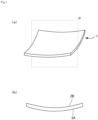
- Fig. 1(a) is a bird' s eye view showing a heat dissipation member (heat dissipation member 1) according to an embodiment.
- the heat dissipation member 1 is plate-shaped.
- a main material of the heat dissipation member 1 is a metal-silicon carbide composite containing aluminum or magnesium (the details of the material will be described below together with a method of manufacturing the heat dissipation member 1).
- the heat dissipation member 1 is substantially rectangular. That is, the heat dissipation member 1 is substantially rectangular in a top view where one main surface or the other main surface is a top surface.
- being substantially rectangular represents that at least one of four corners of the heat dissipation member 1 may have a slightly rounded shape without being linear (of course, the four corners may be linear).
- the rectangular "apex" is defined as an intersection point when straight line portions of a short side and a long side of the heat dissipation member 1 in a top view where one main surface of the heat dissipation member 1 is a top surface are extended.
- the length of the short side or “the length of the long side” of the heat dissipation member 1 is defined by using the above-described "apex" as a starting point or an end point.
- the lengths of the heat dissipation member 1 are, for example, about in a range of 40 mm ⁇ 90 mm to 140 mm ⁇ 250 mm.
- the thickness of the heat dissipation member 1 is, for example, 2 mm or more and 6 mm or less and preferably 3 mm or more and 5 mm or less. If the thickness of the heat dissipation member 1 is not uniform, it is preferable that the thickness of at least a center-of-gravity portion of the heat dissipation member 1 is in the above-described range. Alternatively, when the thickness of the heat dissipation member 1 is not uniform, it is preferable that the thickness in each of portions other than holes is within the above-described range.
- Fig. 1(b) is a cross-sectional view of the heat dissipation member 1 taken along a surface ⁇ of Fig. 1(a) .
- the plate-shaped heat dissipation member 1 includes two main surfaces (one main surface will be referred to as “main surface 2A", and the other main surface will be referred to as “main surface 2B”) .
- the main surface 2A is a surface to be joined to a heat dissipation fin or the like
- the main surface 2B is a surface to be connected to another component such as a power element.
- the main surface 2A is curved to be convex in an outward direction instead of in an inward direction of the heat dissipation member 1.
- the main surface 2B is curved to be convex in the inward direction instead of the outward direction of the heat dissipation member 1 (is curved to be concave in the outward direction of the heat dissipation member 1).
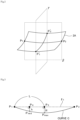
- Fig. 2 is a diagram showing only the main surface 2B of the heat dissipation member 1.
- Fig. 3 shows a curve C of the main surface 2B in a cross-sectional view of the heat dissipation member 1 showing a surface ⁇ (taken along the surface ⁇ ) that is substantially perpendicular to the heat dissipation member 1 and passes both middle points of two short sides of the main surface 2B.
- the curve C is substantially bilaterally symmetrical. That is, "the degree of curve" of the curve C is substantially uniform in the left-right direction.
- P 3 is substantially the middle point of the line segment P 1 P 2 .
- H/L is associated with the degree of "overall" curve of the main surface 2B in the surface ⁇ (in the long side direction of the heat dissipation member 1). H/L can also be referred to as the amount of curve per unit length.
- “the portion close to the end” of the main surface 2B is specifically a portion from the point P 1 to the point P mid in Fig. 3 .
- (2h/L) / (H/L) being 1.1 or more represents that, in the surface ⁇ , the degree of curve of "the portion close to the end" of the main surface 2B is sufficiently higher than the degree of overall curve of the main surface 2B.
- the degree of curve of a portion (accordingly, a particularly highly deformed portion) to which a particularly strong strength is applied when the heat dissipation member 1 is joined to another component with a fixing member such as a screw is relatively high, whereas the degree of curve of the vicinity of the center (portion to which a component such as a power element is to be connected) is relatively low.
- the degree of curve of a portion close to an end of the heat dissipation member 1, that is, a portion to which a particularly strong strength is applied when the heat dissipation member 1 is joined to another component (for example, a heat dissipation fin) with a fixing member such as a screw is relatively high.
- the heat dissipation member 1 can be easily made to be more "flat” "as a whole".
- "gap" between the heat dissipation member 1 and the other component for example, a heat dissipation fin
- joinability and heat dissipation can be further improved.
- (2h/L)/(H/L) is 1.1 or more, preferably 1.3 or more and 2.0 or less, and more preferably 1.4 or more and 1.6 or less.
- the heat dissipation member 1 can be easily made to be "flat" with an appropriate (not excessively high) force.
- the heat dissipation member 1 will be described in more detail.
- the main surface 2B can be easily made to be "flat" to a just right degree with a force by a typical fixing member (for example, a screw). That is, the joinability between the heat dissipation member 1 and another component can be further improved.
- H/L is 5.0 ⁇ 10 -4 or more and 6.0 ⁇ 10 -3 or less and more preferably 1.0 ⁇ 10 -3 or more and 3.0 ⁇ 10 -3 or less.
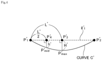
- Fig. 4 shows a curve C' of the main surface 2B of the heat dissipation member 1 of Fig. 2 in a cross-sectional view of the heat dissipation member 1 showing the surface ⁇ (taken along the surface ⁇ ) that is substantially perpendicular to the heat dissipation member 1 and passes both middle points of two short sides of the main surface 2B.
- (2h'/L')/(H'/L') is preferably 1.1 or more, more preferably 1.3 or more and 2.0 or less, and still more preferably 1.4 or more and 1.6 or less.
- the degree of curve of "the portion close to an end" of the main surface 2B not only in “the direction of the surface ⁇ " (the long side direction of the heat dissipation member 1) of Fig. 2 and but also in “the direction of the surface ⁇ " (the short side direction of the heat dissipation member 1) of Fig. 2 to be appropriately high, easy connection of a power element, joinability to a heat dissipation fin, and the like can be further improved.
- the heat dissipation member 1 in particular, by appropriately designing the curved shape of the main surface 2B side, the effect of, for example, improving the manufacturing stability during the manufacturing of a power module can be obtained, and it is preferable to appropriately design the curved shape of the main surface 2A side.
- the curved shape of the main surface 2A is formed such that the degree of curve of "the portion close to an end" is relatively high and the degree of curve of the vicinity of the center is relatively low.
- L, H, h, L', H', h', and the like of the main surface 2A are defined with respect to the drawing where "the main surface 2B" of Fig. 2 is replaced with "the main surface 2A"
- the relationship between L, H, and h in the main surface 2A is the same as that in the main surface 2B (for example, (2h/L) / (H/L) is 1.1 or more)
- the relationship between L' , H', and h' is also the same (for example, (2h'/L')/(H'/L') is 1.1 or more).
- the main surface 2A As described above from the viewpoint of easily manufacturing the heat dissipation member 1.
- the heat dissipation member 1 in which the degrees of curve of the main surface 2A and the main surface 2B are substantially the same can be relatively easily manufactured by heating press or the like described below.
- a through hole is provided in a peripheral portion of the heat dissipation member 1.
- peripheral portion can be defined as a portion corresponding to at least any one of the following (1) and (2) in a top view of the heat dissipation member 1 from the main surface 2B side.
- the through hole is included in the region (1) or (2) (or in a region where (1) and (2) overlap each other).
- the through hole is provided in the peripheral portion of a long side of the heat dissipation member 1 (the region (1) or the region where (1) and (2) overlap each other) .
- the heat dissipation member 1 has specific curve in the short side direction (in the direction of the surface ⁇ in Fig. 2 ). Accordingly, by providing the through hole in the peripheral portion of a long side of the heat dissipation member 1 and joining the heat dissipation member 1 to another component (for example, a heat dissipation fin) through the through hole with a screw, the flatness of the main surface 2B particularly in the short side direction can be further improved.
- the number of through holes is preferably 4 or more, more preferably 4 or more and 8 or less, and still more preferably 4 or more and 6 or less.
- the heat dissipation member 1 includes at least one through hole in the region where (1) and (2) overlap each other (that is, the peripheral portion of four corners of the heat dissipation member 1).
- the diameter of the through hole is, for example, 5 mm or more and 9 mm or less and preferably 6 mm or more and 8 mm or less.
- a unit that joins the heat dissipation member 1 to another component is not limited to a screw.
- the heat dissipation member 1 may be joined to another component using a dedicated jig capable of attaching the heat dissipation member 1 to another component.
- a method of manufacturing the heat dissipation member according to the embodiment is not particularly limited and can be manufactured appropriately using a well-known method.
- the heat dissipation member according to the embodiment can be manufactured through steps including: a preparation step of preparing a metal-silicon carbide composite containing aluminum or magnesium (hereinafter, simply referred to as "preparation step”) ; and a heating press step of interposing the metal-silicon carbide composite between convex and concave molds and heating and pressing the metal-silicon carbide composite (hereafter, simply referred to as "heating press step").
- the heat dissipation member according to the embodiment can be manufactured by preparing a flat metal-silicon carbide composite having no curve or small curve first, interposing the metal-silicon carbide composite between convex and concave molds having an appropriate curved shape, and heating and pressing the metal-silicon carbide composite.
- a method that is preferably used for manufacturing the metal-silicon carbide composite containing aluminum or magnesium is a high-pressure forging method of impregnating a porous body with a metal at a high pressure. More specifically, squeeze casting or die casting can be adopted.
- a porous silicon carbide body (preform) is charged into a high-pressure container, and is impregnated with molten metal containing aluminum or magnesium at a high pressure to obtain a composite.
- squeeze casting is more preferable due to the reason that a large number of products can be stably manufactured.
- the manufacturing method using squeeze casting will be described.
- a flat porous silicon carbide body (SiC preform) is formed.
- the manufacturing method is not particularly limited, and a well-known method can be manufactured.
- the porous silicon carbide body can be manufactured by adding silica, alumina, or the like as a binder to silicon carbide (SiC) powder as a raw material, mixing the components, molding and calcinating the mixture at 800°C or higher.
- silica, alumina, or the like may be used as a raw material, and the porous silicon carbide body does not need to be formed of only silicon carbide as a chemical component.
- the porous silicon carbide body only needs to be formed of 50 mass% or higher of silicon carbide with respect to the total mass.
- a molding method is not particularly limited, press molding, extrusion molding, cast molding, or the like can be used.
- a binder for shape retention can be used in combination.
- the metal-silicon carbide composite obtained by impregnating the porous silicon carbide body with a metal containing aluminum or magnesium are thermal conductivity and a thermal expansion coefficient. It is preferable that the SiC content in the porous silicon carbide body is high because the thermal conductivity is high and the thermal expansion coefficient is low. It is noted that, when the content is excessively high, the porous silicon carbide body is not sufficiently impregnated with a metal.
- the relative density of the SiC preform is preferably in a range of 55% or higher and 75% or lower.
- the bending strength of the porous silicon carbide body (SiC preform) is preferably 3 MPa or higher in order to prevent fracturing during handling or impregnation.
- the average particle size can be measured by calculating the average value of particle sizes of 1000 particles using a scanning electron microscope (for example, "JSM-T200 model", manufactured by JEOL Ltd.) and an image analyzer (for example, manufactured by Nippon Avionics Co., Ltd.).
- the relative density can be measured using the Archimedes method or the like.
- the particle size of the SiC powder as a raw material of the porous silicon carbide body (SiC preform) is adjusted by appropriately using coarse powder and fine powder in combination.
- the strength of the porous silicon carbide body (SiC preform) and the thermal conductivity of the heat dissipation member that is finally obtained can be improved at a high level.
- mixed powder obtained by mixing (i) SiC coarse powder having an average particle size of 40 um or more and 150 um or less and (ii) SiC fine powder having an average particle size of 5 um or more and 15 um or less is suitable.
- the amount of (i) is 40 mass% or higher and 80 mass% or lower, and the amount of (ii) is preferably 20 mass% or higher and 60 mass% or lower.
- the porous silicon carbide body (SiC preform) is obtained by, for example, degreasing and calcinating a compact of a mixture obtained by adding the binder to the SiC powder.
- the calcination temperature is 800°C or higher, a porous silicon carbide body (SiC preform) having a bending strength of 3 MPa or higher is likely to be obtained irrespective of the atmosphere during the calcination.
- the calcination is performed at a temperature exceeding 1100°C in an oxidizing atmosphere, the oxidation of SiC is promoted, and the thermal conductivity of the metal-silicon carbide composite may decrease. Accordingly, it is preferable that the calcination is performed at a temperature of 1100°C or lower in the oxidizing atmosphere.
- the calcination time may be appropriately determined depending on conditions such as the size of the porous silicon carbide body (SiC preform), the amount of raw materials charged into a calcination furnace, or the calcination atmosphere.
- a change in shape (for example, change in the amount of curve) caused by drying can be prevented by performing drying one by one or by performing drying using a spacer such as carbon having the same shape as the preform shape between SiC preforms.
- a spacer such as carbon having the same shape as the preform shape between SiC preforms.
- the metal-silicon carbide composite By impregnating the porous silicon carbide body (SiC preform) obtained as described above with a metal containing aluminum or magnesium using the high-pressure forging method or the like, the metal-silicon carbide composite can be obtained.
- Examples of a method of obtaining the metal-silicon carbide composite by impregnating the porous silicon carbide body (SiC preform) with the metal (alloy) containing aluminum or magnesium include the following method.
- the porous silicon carbide body (SiC preform) is set into a mold.
- molten metal metal containing aluminum or magnesium
- voids of the porous silicon carbide body (SiC preform) are impregnated with the metal.
- the metal-silicon carbide composite is obtained.
- the porous silicon carbide body (SiC preform) when the porous silicon carbide body (SiC preform) is set into the mold, it is preferable to preheat the mold.
- the preheating temperature is, for example, 500°C or higher and 650°C or lower.
- the molten metal is charged as rapidly as possible after setting the porous silicon carbide body (SiC preform) into the mold.
- a surface metal layer may be provided on a surface (for example, a main surface) of the metal-silicon carbide composite.
- a heat dissipation member in which the surface metal layer (specifically, the surface metal layer containing aluminum or magnesium) is provided on surfaces such as two main surfaces can be obtained.
- a mold having a slightly larger dimension than the dimension of the SiC preform is prepared as the mold for the impregnation, the SiC preform is disposed in the mold, and the molten metal is poured thereinto.
- the surface metal layer can be provided.
- the surface metal layer can be provided by impregnating the SiC preform with the metal in a state where one or more kinds among fibers, spherical particles, and crushed particles formed of alumina or silica are disposed to be in direct contact with the surface of the SiC preform.
- the content of the material including one or more kinds among fibers, spherical particles, and crushed particles formed of alumina or silica in the surface metal layer is preferably 5 mass% or higher and 40 mass% or lower and more preferably 10 mass% or higher and 20 mass% or lower with respect to the mass of the metal-silicon carbide composite.
- the surface metal layer can be provided using a method of disposing a thin sheet or a thin film of the metal on the surface of the SiC preform and then impregnating the SiC preform with the metal, a method of providing a groove or the like on the surface of the SiC preform in advance, or the like.
- the press pressure of the molten metal is not particularly limited as long as the metal can be sufficiently impregnated, and is, for example, 30 MPa or higher.
- the melting point of the metal (preferably, the alloy containing aluminum or magnesium) to be impregnated is appropriately low so as to sufficiently permeate into the voids of the preform.
- an aluminum alloy containing 7 mass% or higher and 25 mass% or lower of silicon is preferable. Further, it is preferable that 0.2 mass% or higher and 5 mass% or lower of magnesium is contained from the viewpoint that the binding between the silicon carbide particle and the metal portion becomes more strong.
- Metal components in the aluminum alloy other than aluminum, silicon, and magnesium are not particularly limited within a range where characteristics do not change extremely. For example, copper may be included.
- the aluminum alloy for example, AC4C, AC4CH, or ADC12 that is an alloy for forging can be preferably used.
- an annealing treatment may be performed on the metal-silicon carbide composite.
- the annealing treatment can be performed, for example, under conditions of a temperature of about 400°C or higher and 550°C or lower and 10 minutes or longer.
- the metal-silicon carbide composite (flat plate-shaped) obtained in the above-described preparation step is typically flat or has uncontrolled curve.
- a heat dissipation member to which appropriate curve is imparted can be obtained.
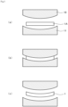
- a metal-silicon carbide composite 1A is interposed between a press convex mold 10 and a press concave mold 11 and is heated and pressed (pressed while being heated) .
- the heat dissipation member 1 to which predetermined curve is imparted can be obtained.
- the press convex mold 10 and the press concave mold 11 are processed in a shape such that the predetermined curve is imparted to the heat dissipation member 1.
- a mold having a relatively small curvature in a center portion and a relatively large curvature in a portion distant from the center portion is used. The same is applicable to the press concave mold 11.
- the form of a convex portion of the press convex mold 10 and the form of a concave portion of the press concave mold 11 are substantially the same. That is, typically, when the press convex mold 10 and the press concave mold 11 overlap each other without interposing the metal-silicon carbide composite 1A therebetween, there is substantially no gap between the press convex mold 10 and the press concave mold 11.
- Materials of the press convex mold 10 and the press concave mold 11 are not particularly limited and may be any one as long as they are not substantially deformed under temperature and pressure conditions described below. Specifically, a ceramic such as carbon or boron nitride or a metal material such as cemented carbide or stainless steel is preferably used.
- the heating temperature during the heating press is not particularly limited. However, from the viewpoints of obtaining productivity and reducing the pressure, it is preferable that the heating temperature is as high as possible within a range where the metal in the metal-silicon carbide composite 1A does not melt. In the embodiment, the heating temperature is preferably 450°C or higher and 550°C or lower in consideration of the fact that the metal in the metal-silicon carbide composite 1A is aluminum, magnesium, or the like (including an alloy thereof).
- the pressure during the heating press is not particularly limited.
- the pressure may be appropriately adjusted depending on the thickness of the metal-silicon carbide composite 1A, the heating temperature, and the like.
- the pressure is preferably 10 kPa or higher and more preferably 30 kPa or higher and 250 kPa or lower.
- the time during the heating press is not particularly limited.
- the time at which the temperature of the metal-silicon carbide composite 1A itself is 450° or higher is preferably 30 seconds or longer and more preferably 30 seconds or longer and 300 seconds or shorter.
- the heating press step may be performed multiple times.
- the second heating press step may be performed using the second press convex mold 10 and the second press concave mold 11 having a curved shape different from that of the first press convex mold 10 and the first press concave mold 11.
- Cooling may be, for example, rapid cooling or air cooling.
- the curve may change depending on a cooling method. Therefore, in order to obtain desired curve, it is preferable to appropriately set cooling conditions.
- the press convex mold 10 and the press concave mold 11 having an appropriate shape and to appropriately adjust and optimize the temperature and time of the heating press, a specific cooling method after the heating press, and the like.
- the adjustment and optimization described herein is not that difficult by grasping the degree of curve through some preliminary experiments.
- the method of manufacturing the heat dissipation member according to the embodiment may include another step other than the above-described steps.
- a step of providing the hole for screwing may be provided.
- the hole for screwing for joining to another component can be provided by mechanical processing or the like. Since a position where the hole for screwing is provided and the like are as described above, the description thereof will not be repeated.
- a step of providing the hole for screwing can be performed, for example, between the preparation step and the heating press step.
- the step of providing the hole for screwing can be performed after the heating press step.
- a step of mechanically processing at least a part of the surface of the heat dissipation member 1 may be performed.
- mechanical processing includes cutting, grinding, polishing, and the like.
- connection to a power element can be performed more easily, or the joinability to a heat dissipation fin can be further improved.
- the surface of the heat dissipation member 1 for example, the main surface 2A or 2B
- the surface roughness can be appropriately adjusted, and the connectivity of a power element or the joinability to a heat dissipation fin or the like can be further improved.
- Both surfaces of the porous silicon carbide body were interposed between stainless steel (SUS 304) sheets having a dimension of 210 mm ⁇ 160 mm ⁇ 0.8 mm and having both surfaces to which a release agent was applied, and 30 bodies were laminated. Further, an iron sheet having a thickness of 6 mm was disposed at both ends and fixed using bolts and nuts having a diameter of 10 mm ⁇ such that one block was formed.
- SUS 304 stainless steel
- the above-described block was preheated using an electric furnace at a temperature of 600°C. Next, this block was put into a press mold having a void with an internal dimension of 400 mm ⁇ ⁇ 300 mm that was heated in advance.
- molten aluminum alloy having a temperature of 800°C and having a composition including 12% of silicon, 1% of magnesium, and a remainder consisting of aluminum and inevitable impurities was poured into the press mold and was pressurized at a pressure of 100 MPa for 20 minutes.
- the porous silicon carbide body was impregnated with the aluminum alloy to obtain a metal block including the aluminum-silicon carbide composite.
- the obtained metal block was cooled to room temperature and was cut along a side surface shape of a release sheet using a wet bandsaw to remove the interposed stainless steel sheets.
- the outer periphery of the obtained aluminum-silicon carbide composite was processed with an NC lathe such that the lengths were 180 mm ⁇ 130 mm.
- an NC lathe such that the lengths were 180 mm ⁇ 130 mm.
- through holes having a diameter of 7 mm were formed at eight positions, and countersunk holes having a diameter ⁇ of 10-4 mm were formed at four positions.
- a press convex mold and a press concave mold were prepared. Specifically, in order to obtain a desired curved shape, a press convex mold and a press concave mold having a relatively small curvature in a center portion and a relatively large curvature in a portion distant from the center portion were prepared.
- the convex and concave molds were mounted on a heating press machine and were heated such that the surface temperature of the molds were 460°C.
- the aluminum-silicon carbide composite was disposed between the convex and concave molds and was pressed at 40 kPa. At this time, a thermocouple was brought into contact with a side surface of the composite to measure the temperature. After the temperature of the composite reached 450°C, the composite was held at this temperature for 3 minutes, the pressurization was released, the composite was naturally cooled to room temperature.
- the composite was blasted and cleaned with alumina abrasive grains under conditions of pressure: 0.4 MPa, transport speed: 1.0 m/min. Further, next, electroless Ni-P plating and Ni-B plating were performed. As a result, a plating layer having a thickness of 8 um (Ni-P: 6 pm, Ni-B: 2 um) was formed on the surface of the composite.
- Heat dissipation members were prepared using the same method as that of Example 1, except that the lengths of a long side and a short side of the heat dissipation member and the curved shapes of the press convex mold and the press concave mold in the above (Imparting of Curve) were changed. Next, various numerical values were measured using the same methods as those of Example 1.
- the values of L, H, h, and the like shown in Table 1 are values measured for the main surface (the other main surface; the main surface 2B in Fig. 1(b) ) curved to be convex in the inward direction of the heat dissipation member.
- a ceramic substrate (substrate having both surfaces where a metal layer such as copper or aluminum was provided) was soldered to six specific positions of the main surface 2B among two main surfaces of the heat dissipation member according to each of Examples and Comparative Examples. As a result, a substrate for a simulated power module was obtained.
- the obtained simulated power module was investigated for whether or not a defect causing a problem relating to mass production was present.
- the heat dissipation member according to each of Examples 1 to 7 was joined to a heat dissipation fin with a screw, and adhesion between the heat dissipation member and the heat dissipation fin, heat dissipation, and the like were evaluated. As a result, the adhesion and the heat dissipation were excellent.
- Comparative Example 1 a tool for aligning the ceramic substrate was not suitably fitted, and it was difficult to perform the connection of the component itself.
Landscapes
- Engineering & Computer Science (AREA)
- Chemical & Material Sciences (AREA)
- Ceramic Engineering (AREA)
- Materials Engineering (AREA)
- Organic Chemistry (AREA)
- Physics & Mathematics (AREA)
- Structural Engineering (AREA)
- Thermal Sciences (AREA)
- Manufacturing & Machinery (AREA)
- Microelectronics & Electronic Packaging (AREA)
- Mechanical Engineering (AREA)
- Inorganic Chemistry (AREA)
- Computer Hardware Design (AREA)
- Condensed Matter Physics & Semiconductors (AREA)
- General Physics & Mathematics (AREA)
- Power Engineering (AREA)
- General Engineering & Computer Science (AREA)
- Plasma & Fusion (AREA)
- Combustion & Propulsion (AREA)
- Chemical Kinetics & Catalysis (AREA)
- Cooling Or The Like Of Semiconductors Or Solid State Devices (AREA)
Applications Claiming Priority (2)
| Application Number | Priority Date | Filing Date | Title |
|---|---|---|---|
| JP2019013765A JP7116690B2 (ja) | 2019-01-30 | 2019-01-30 | 放熱部材およびその製造方法 |
| PCT/JP2020/003090 WO2020158775A1 (ja) | 2019-01-30 | 2020-01-29 | 放熱部材およびその製造方法 |
Publications (3)
| Publication Number | Publication Date |
|---|---|
| EP3920214A1 EP3920214A1 (en) | 2021-12-08 |
| EP3920214A4 EP3920214A4 (en) | 2022-03-23 |
| EP3920214B1 true EP3920214B1 (en) | 2024-08-07 |
Family
ID=71841807
Family Applications (1)
| Application Number | Title | Priority Date | Filing Date |
|---|---|---|---|
| EP20747772.0A Active EP3920214B1 (en) | 2019-01-30 | 2020-01-29 | Heat-dissipating member and manufacturing method for same |
Country Status (5)
| Country | Link |
|---|---|
| US (1) | US12069837B2 (enExample) |
| EP (1) | EP3920214B1 (enExample) |
| JP (1) | JP7116690B2 (enExample) |
| CN (1) | CN112997300B (enExample) |
| WO (1) | WO2020158775A1 (enExample) |
Families Citing this family (5)
| Publication number | Priority date | Publication date | Assignee | Title |
|---|---|---|---|---|
| US12306455B2 (en) | 2021-10-05 | 2025-05-20 | Raytheon Company | Multiaxial thermal dissipation and structurally-compliant device |
| US12236571B2 (en) | 2021-10-05 | 2025-02-25 | Raytheon Company | Integrated Dewar assembly with compliant endcap cooling |
| EP4411810A4 (en) * | 2021-10-06 | 2025-02-12 | Denka Company Limited | Heat dissipation member |
| CN114851352B (zh) * | 2022-05-23 | 2023-11-28 | 松山湖材料实验室 | 电阻加热元件及其制造方法 |
| CN120752754A (zh) * | 2023-02-27 | 2025-10-03 | 电化株式会社 | 陶瓷板、包装体、陶瓷板的制造方法、模块及电气电子产品 |
Family Cites Families (23)
| Publication number | Priority date | Publication date | Assignee | Title |
|---|---|---|---|---|
| JPS468358B1 (enExample) | 1967-01-27 | 1971-03-02 | ||
| JP3468358B2 (ja) | 1998-11-12 | 2003-11-17 | 電気化学工業株式会社 | 炭化珪素質複合体及びその製造方法とそれを用いた放熱部品 |
| JP2002246515A (ja) | 2001-02-20 | 2002-08-30 | Mitsubishi Electric Corp | 半導体装置 |
| JP4267947B2 (ja) * | 2003-03-19 | 2009-05-27 | 日本碍子株式会社 | ハニカム構造体 |
| JP3907620B2 (ja) | 2003-11-14 | 2007-04-18 | 電気化学工業株式会社 | セラミックス回路基板一体型アルミニウム−炭化珪素質複合体及びその製造方法 |
| CN101361184B (zh) | 2006-01-13 | 2011-04-13 | 电气化学工业株式会社 | 铝-碳化硅复合体和使用该复合体的散热零件 |
| JP4996600B2 (ja) * | 2006-04-26 | 2012-08-08 | 電気化学工業株式会社 | アルミニウム−炭化珪素質複合体及びそれを用いた放熱部品 |
| JP4864593B2 (ja) | 2006-08-08 | 2012-02-01 | 電気化学工業株式会社 | アルミニウム−炭化珪素質複合体の製造方法 |
| US8092624B2 (en) * | 2006-12-07 | 2012-01-10 | Ngk Insulators, Ltd. | Bonding material composition and method for manufacturing the same, and joined body and method for manufacturing the same |
| JP2010227755A (ja) * | 2009-03-26 | 2010-10-14 | Ngk Insulators Ltd | セラミックハニカム構造体 |
| WO2012071353A1 (en) * | 2010-11-22 | 2012-05-31 | Saint-Gobain Ceramics & Plastics, Inc. | Infiltrated silicon carbide bodies and methods of making |
| CN105580131B (zh) | 2013-10-10 | 2021-03-12 | 三菱综合材料株式会社 | 自带散热器的功率模块用基板及其制造方法 |
| CN105981162A (zh) | 2014-02-03 | 2016-09-28 | 电化株式会社 | 碳化硅质复合体及其制造方法以及使用该复合体的散热零件 |
| WO2016017689A1 (ja) | 2014-07-31 | 2016-02-04 | 電気化学工業株式会社 | アルミニウム‐炭化珪素質複合体及びその製造方法 |
| CN106796920B (zh) | 2014-08-06 | 2019-09-24 | 电化株式会社 | 散热部件及其制造方法 |
| JP7048493B2 (ja) | 2016-07-14 | 2022-04-05 | 株式会社東芝 | セラミックス回路基板および半導体モジュール |
| CN110036473B (zh) | 2016-12-06 | 2023-09-05 | 联合材料公司 | 复合构件、散热构件、半导体装置和制造复合构件的方法 |
| JP6717238B2 (ja) | 2017-03-07 | 2020-07-01 | 三菱マテリアル株式会社 | ヒートシンク付パワーモジュール用基板 |
| CN110998839B (zh) * | 2017-08-04 | 2023-07-04 | 电化株式会社 | 功率模块 |
| JP6646116B2 (ja) | 2018-08-09 | 2020-02-14 | 株式会社カプコン | 映像音声処理プログラム及びゲーム装置 |
| JP7199988B2 (ja) * | 2019-02-08 | 2023-01-06 | 日本碍子株式会社 | ハニカム構造体の製造方法 |
| FR3094039B1 (fr) * | 2019-03-21 | 2021-03-19 | Faurecia Systemes Dechappement | Organe de chauffage durable pour dispositif de purification des gaz d’échappement d’un véhicule |
| JP6591114B1 (ja) * | 2019-06-05 | 2019-10-16 | デンカ株式会社 | 放熱部材およびその製造方法 |
-
2019
- 2019-01-30 JP JP2019013765A patent/JP7116690B2/ja active Active
-
2020
- 2020-01-29 EP EP20747772.0A patent/EP3920214B1/en active Active
- 2020-01-29 WO PCT/JP2020/003090 patent/WO2020158775A1/ja not_active Ceased
- 2020-01-29 CN CN202080006007.8A patent/CN112997300B/zh active Active
- 2020-01-29 US US17/425,541 patent/US12069837B2/en active Active
Also Published As
| Publication number | Publication date |
|---|---|
| CN112997300B (zh) | 2023-03-24 |
| US20220369499A1 (en) | 2022-11-17 |
| JP7116690B2 (ja) | 2022-08-10 |
| EP3920214A1 (en) | 2021-12-08 |
| CN112997300A (zh) | 2021-06-18 |
| EP3920214A4 (en) | 2022-03-23 |
| US12069837B2 (en) | 2024-08-20 |
| JP2020123639A (ja) | 2020-08-13 |
| WO2020158775A1 (ja) | 2020-08-06 |
Similar Documents
| Publication | Publication Date | Title |
|---|---|---|
| EP3920214B1 (en) | Heat-dissipating member and manufacturing method for same | |
| EP3920215B1 (en) | Heat-dissipating member and manufacturing method for same | |
| EP2012354B1 (en) | Method of producing a base plate for a power module | |
| EP1973157B1 (en) | Aluminum/silicon carbide composite and heat dissipation device employing the same | |
| EP3121847B1 (en) | Aluminium-silicon carbide composite, and power-module base plate | |
| EP3890007B1 (en) | Heat dissipation member | |
| US11296008B2 (en) | Aluminum-silicon carbide composite and production method therefor | |
| JP7050978B1 (ja) | 成形体及びその製造方法 | |
| JP6591114B1 (ja) | 放熱部材およびその製造方法 | |
| EP4411809A1 (en) | Heat dissipation member | |
| JP6591113B1 (ja) | 放熱部材およびその製造方法 | |
| EP4411810A1 (en) | Heat dissipation member | |
| EP4549056A1 (en) | Method of manufacturing bonded body, bonded body, and heat sink |
Legal Events
| Date | Code | Title | Description |
|---|---|---|---|
| STAA | Information on the status of an ep patent application or granted ep patent |
Free format text: STATUS: THE INTERNATIONAL PUBLICATION HAS BEEN MADE |
|
| PUAI | Public reference made under article 153(3) epc to a published international application that has entered the european phase |
Free format text: ORIGINAL CODE: 0009012 |
|
| STAA | Information on the status of an ep patent application or granted ep patent |
Free format text: STATUS: REQUEST FOR EXAMINATION WAS MADE |
|
| 17P | Request for examination filed |
Effective date: 20210823 |
|
| AK | Designated contracting states |
Kind code of ref document: A1 Designated state(s): AL AT BE BG CH CY CZ DE DK EE ES FI FR GB GR HR HU IE IS IT LI LT LU LV MC MK MT NL NO PL PT RO RS SE SI SK SM TR |
|
| A4 | Supplementary search report drawn up and despatched |
Effective date: 20220223 |
|
| RIC1 | Information provided on ipc code assigned before grant |
Ipc: H01L 23/373 20060101ALI20220217BHEP Ipc: H01L 21/48 20060101ALI20220217BHEP Ipc: C04B 41/88 20060101ALI20220217BHEP Ipc: H01L 23/36 20060101AFI20220217BHEP |
|
| DAV | Request for validation of the european patent (deleted) | ||
| DAX | Request for extension of the european patent (deleted) | ||
| STAA | Information on the status of an ep patent application or granted ep patent |
Free format text: STATUS: EXAMINATION IS IN PROGRESS |
|
| 17Q | First examination report despatched |
Effective date: 20230620 |
|
| GRAP | Despatch of communication of intention to grant a patent |
Free format text: ORIGINAL CODE: EPIDOSNIGR1 |
|
| STAA | Information on the status of an ep patent application or granted ep patent |
Free format text: STATUS: GRANT OF PATENT IS INTENDED |
|
| RIC1 | Information provided on ipc code assigned before grant |
Ipc: C04B 41/90 20060101ALI20240126BHEP Ipc: C04B 41/52 20060101ALI20240126BHEP Ipc: C04B 41/45 20060101ALI20240126BHEP Ipc: C04B 41/00 20060101ALI20240126BHEP Ipc: H01L 23/373 20060101ALI20240126BHEP Ipc: H01L 21/48 20060101ALI20240126BHEP Ipc: C04B 41/88 20060101ALI20240126BHEP Ipc: H01L 23/36 20060101AFI20240126BHEP |
|
| INTG | Intention to grant announced |
Effective date: 20240301 |
|
| GRAS | Grant fee paid |
Free format text: ORIGINAL CODE: EPIDOSNIGR3 |
|
| GRAA | (expected) grant |
Free format text: ORIGINAL CODE: 0009210 |
|
| STAA | Information on the status of an ep patent application or granted ep patent |
Free format text: STATUS: THE PATENT HAS BEEN GRANTED |
|
| AK | Designated contracting states |
Kind code of ref document: B1 Designated state(s): AL AT BE BG CH CY CZ DE DK EE ES FI FR GB GR HR HU IE IS IT LI LT LU LV MC MK MT NL NO PL PT RO RS SE SI SK SM TR |
|
| REG | Reference to a national code |
Ref country code: GB Ref legal event code: FG4D |
|
| REG | Reference to a national code |
Ref country code: CH Ref legal event code: EP |
|
| P01 | Opt-out of the competence of the unified patent court (upc) registered |
Free format text: CASE NUMBER: APP_42845/2024 Effective date: 20240722 |
|
| REG | Reference to a national code |
Ref country code: IE Ref legal event code: FG4D |
|
| REG | Reference to a national code |
Ref country code: DE Ref legal event code: R096 Ref document number: 602020035348 Country of ref document: DE |
|
| REG | Reference to a national code |
Ref country code: LT Ref legal event code: MG9D |
|
| REG | Reference to a national code |
Ref country code: NL Ref legal event code: MP Effective date: 20240807 |
|
| PG25 | Lapsed in a contracting state [announced via postgrant information from national office to epo] |
Ref country code: NO Free format text: LAPSE BECAUSE OF FAILURE TO SUBMIT A TRANSLATION OF THE DESCRIPTION OR TO PAY THE FEE WITHIN THE PRESCRIBED TIME-LIMIT Effective date: 20241107 |
|
| REG | Reference to a national code |
Ref country code: AT Ref legal event code: MK05 Ref document number: 1711933 Country of ref document: AT Kind code of ref document: T Effective date: 20240807 |
|
| PG25 | Lapsed in a contracting state [announced via postgrant information from national office to epo] |
Ref country code: NL Free format text: LAPSE BECAUSE OF FAILURE TO SUBMIT A TRANSLATION OF THE DESCRIPTION OR TO PAY THE FEE WITHIN THE PRESCRIBED TIME-LIMIT Effective date: 20240807 Ref country code: PT Free format text: LAPSE BECAUSE OF FAILURE TO SUBMIT A TRANSLATION OF THE DESCRIPTION OR TO PAY THE FEE WITHIN THE PRESCRIBED TIME-LIMIT Effective date: 20241209 Ref country code: FI Free format text: LAPSE BECAUSE OF FAILURE TO SUBMIT A TRANSLATION OF THE DESCRIPTION OR TO PAY THE FEE WITHIN THE PRESCRIBED TIME-LIMIT Effective date: 20240807 Ref country code: PL Free format text: LAPSE BECAUSE OF FAILURE TO SUBMIT A TRANSLATION OF THE DESCRIPTION OR TO PAY THE FEE WITHIN THE PRESCRIBED TIME-LIMIT Effective date: 20240807 Ref country code: GR Free format text: LAPSE BECAUSE OF FAILURE TO SUBMIT A TRANSLATION OF THE DESCRIPTION OR TO PAY THE FEE WITHIN THE PRESCRIBED TIME-LIMIT Effective date: 20241108 |
|
| PGFP | Annual fee paid to national office [announced via postgrant information from national office to epo] |
Ref country code: GB Payment date: 20241205 Year of fee payment: 6 |
|
| PG25 | Lapsed in a contracting state [announced via postgrant information from national office to epo] |
Ref country code: BG Free format text: LAPSE BECAUSE OF FAILURE TO SUBMIT A TRANSLATION OF THE DESCRIPTION OR TO PAY THE FEE WITHIN THE PRESCRIBED TIME-LIMIT Effective date: 20240807 |
|
| PG25 | Lapsed in a contracting state [announced via postgrant information from national office to epo] |
Ref country code: LV Free format text: LAPSE BECAUSE OF FAILURE TO SUBMIT A TRANSLATION OF THE DESCRIPTION OR TO PAY THE FEE WITHIN THE PRESCRIBED TIME-LIMIT Effective date: 20240807 |
|
| PG25 | Lapsed in a contracting state [announced via postgrant information from national office to epo] |
Ref country code: AT Free format text: LAPSE BECAUSE OF FAILURE TO SUBMIT A TRANSLATION OF THE DESCRIPTION OR TO PAY THE FEE WITHIN THE PRESCRIBED TIME-LIMIT Effective date: 20240807 Ref country code: IS Free format text: LAPSE BECAUSE OF FAILURE TO SUBMIT A TRANSLATION OF THE DESCRIPTION OR TO PAY THE FEE WITHIN THE PRESCRIBED TIME-LIMIT Effective date: 20241207 |
|
| PG25 | Lapsed in a contracting state [announced via postgrant information from national office to epo] |
Ref country code: HR Free format text: LAPSE BECAUSE OF FAILURE TO SUBMIT A TRANSLATION OF THE DESCRIPTION OR TO PAY THE FEE WITHIN THE PRESCRIBED TIME-LIMIT Effective date: 20240807 |
|
| PG25 | Lapsed in a contracting state [announced via postgrant information from national office to epo] |
Ref country code: RS Free format text: LAPSE BECAUSE OF FAILURE TO SUBMIT A TRANSLATION OF THE DESCRIPTION OR TO PAY THE FEE WITHIN THE PRESCRIBED TIME-LIMIT Effective date: 20241107 Ref country code: ES Free format text: LAPSE BECAUSE OF FAILURE TO SUBMIT A TRANSLATION OF THE DESCRIPTION OR TO PAY THE FEE WITHIN THE PRESCRIBED TIME-LIMIT Effective date: 20240807 |
|
| PG25 | Lapsed in a contracting state [announced via postgrant information from national office to epo] |
Ref country code: RS Free format text: LAPSE BECAUSE OF FAILURE TO SUBMIT A TRANSLATION OF THE DESCRIPTION OR TO PAY THE FEE WITHIN THE PRESCRIBED TIME-LIMIT Effective date: 20241107 Ref country code: PT Free format text: LAPSE BECAUSE OF FAILURE TO SUBMIT A TRANSLATION OF THE DESCRIPTION OR TO PAY THE FEE WITHIN THE PRESCRIBED TIME-LIMIT Effective date: 20241209 Ref country code: PL Free format text: LAPSE BECAUSE OF FAILURE TO SUBMIT A TRANSLATION OF THE DESCRIPTION OR TO PAY THE FEE WITHIN THE PRESCRIBED TIME-LIMIT Effective date: 20240807 Ref country code: NO Free format text: LAPSE BECAUSE OF FAILURE TO SUBMIT A TRANSLATION OF THE DESCRIPTION OR TO PAY THE FEE WITHIN THE PRESCRIBED TIME-LIMIT Effective date: 20241107 Ref country code: NL Free format text: LAPSE BECAUSE OF FAILURE TO SUBMIT A TRANSLATION OF THE DESCRIPTION OR TO PAY THE FEE WITHIN THE PRESCRIBED TIME-LIMIT Effective date: 20240807 Ref country code: LV Free format text: LAPSE BECAUSE OF FAILURE TO SUBMIT A TRANSLATION OF THE DESCRIPTION OR TO PAY THE FEE WITHIN THE PRESCRIBED TIME-LIMIT Effective date: 20240807 Ref country code: IS Free format text: LAPSE BECAUSE OF FAILURE TO SUBMIT A TRANSLATION OF THE DESCRIPTION OR TO PAY THE FEE WITHIN THE PRESCRIBED TIME-LIMIT Effective date: 20241207 Ref country code: HR Free format text: LAPSE BECAUSE OF FAILURE TO SUBMIT A TRANSLATION OF THE DESCRIPTION OR TO PAY THE FEE WITHIN THE PRESCRIBED TIME-LIMIT Effective date: 20240807 Ref country code: GR Free format text: LAPSE BECAUSE OF FAILURE TO SUBMIT A TRANSLATION OF THE DESCRIPTION OR TO PAY THE FEE WITHIN THE PRESCRIBED TIME-LIMIT Effective date: 20241108 Ref country code: FI Free format text: LAPSE BECAUSE OF FAILURE TO SUBMIT A TRANSLATION OF THE DESCRIPTION OR TO PAY THE FEE WITHIN THE PRESCRIBED TIME-LIMIT Effective date: 20240807 Ref country code: ES Free format text: LAPSE BECAUSE OF FAILURE TO SUBMIT A TRANSLATION OF THE DESCRIPTION OR TO PAY THE FEE WITHIN THE PRESCRIBED TIME-LIMIT Effective date: 20240807 Ref country code: BG Free format text: LAPSE BECAUSE OF FAILURE TO SUBMIT A TRANSLATION OF THE DESCRIPTION OR TO PAY THE FEE WITHIN THE PRESCRIBED TIME-LIMIT Effective date: 20240807 Ref country code: AT Free format text: LAPSE BECAUSE OF FAILURE TO SUBMIT A TRANSLATION OF THE DESCRIPTION OR TO PAY THE FEE WITHIN THE PRESCRIBED TIME-LIMIT Effective date: 20240807 |
|
| PGFP | Annual fee paid to national office [announced via postgrant information from national office to epo] |
Ref country code: DE Payment date: 20241203 Year of fee payment: 6 |
|
| PG25 | Lapsed in a contracting state [announced via postgrant information from national office to epo] |
Ref country code: SM Free format text: LAPSE BECAUSE OF FAILURE TO SUBMIT A TRANSLATION OF THE DESCRIPTION OR TO PAY THE FEE WITHIN THE PRESCRIBED TIME-LIMIT Effective date: 20240807 Ref country code: DK Free format text: LAPSE BECAUSE OF FAILURE TO SUBMIT A TRANSLATION OF THE DESCRIPTION OR TO PAY THE FEE WITHIN THE PRESCRIBED TIME-LIMIT Effective date: 20240807 |
|
| PG25 | Lapsed in a contracting state [announced via postgrant information from national office to epo] |
Ref country code: EE Free format text: LAPSE BECAUSE OF FAILURE TO SUBMIT A TRANSLATION OF THE DESCRIPTION OR TO PAY THE FEE WITHIN THE PRESCRIBED TIME-LIMIT Effective date: 20240807 |
|
| PGFP | Annual fee paid to national office [announced via postgrant information from national office to epo] |
Ref country code: CH Payment date: 20250201 Year of fee payment: 6 |
|
| PG25 | Lapsed in a contracting state [announced via postgrant information from national office to epo] |
Ref country code: CZ Free format text: LAPSE BECAUSE OF FAILURE TO SUBMIT A TRANSLATION OF THE DESCRIPTION OR TO PAY THE FEE WITHIN THE PRESCRIBED TIME-LIMIT Effective date: 20240807 |
|
| PG25 | Lapsed in a contracting state [announced via postgrant information from national office to epo] |
Ref country code: SK Free format text: LAPSE BECAUSE OF FAILURE TO SUBMIT A TRANSLATION OF THE DESCRIPTION OR TO PAY THE FEE WITHIN THE PRESCRIBED TIME-LIMIT Effective date: 20240807 |
|
| REG | Reference to a national code |
Ref country code: DE Ref legal event code: R097 Ref document number: 602020035348 Country of ref document: DE |
|
| PLBE | No opposition filed within time limit |
Free format text: ORIGINAL CODE: 0009261 |
|
| STAA | Information on the status of an ep patent application or granted ep patent |
Free format text: STATUS: NO OPPOSITION FILED WITHIN TIME LIMIT |
|
| 26N | No opposition filed |
Effective date: 20250508 |
|
| PG25 | Lapsed in a contracting state [announced via postgrant information from national office to epo] |
Ref country code: SE Free format text: LAPSE BECAUSE OF FAILURE TO SUBMIT A TRANSLATION OF THE DESCRIPTION OR TO PAY THE FEE WITHIN THE PRESCRIBED TIME-LIMIT Effective date: 20240807 |
|
| PG25 | Lapsed in a contracting state [announced via postgrant information from national office to epo] |
Ref country code: MC Free format text: LAPSE BECAUSE OF FAILURE TO SUBMIT A TRANSLATION OF THE DESCRIPTION OR TO PAY THE FEE WITHIN THE PRESCRIBED TIME-LIMIT Effective date: 20240807 Ref country code: LU Free format text: LAPSE BECAUSE OF NON-PAYMENT OF DUE FEES Effective date: 20250129 |
|
| PG25 | Lapsed in a contracting state [announced via postgrant information from national office to epo] |
Ref country code: BE Free format text: LAPSE BECAUSE OF NON-PAYMENT OF DUE FEES Effective date: 20250131 |
|
| PG25 | Lapsed in a contracting state [announced via postgrant information from national office to epo] |
Ref country code: FR Free format text: LAPSE BECAUSE OF NON-PAYMENT OF DUE FEES Effective date: 20250131 |
|
| REG | Reference to a national code |
Ref country code: BE Ref legal event code: MM Effective date: 20250131 |