EP3920215B1 - Heat-dissipating member and manufacturing method for same - Google Patents
Heat-dissipating member and manufacturing method for same Download PDFInfo
- Publication number
- EP3920215B1 EP3920215B1 EP20748646.5A EP20748646A EP3920215B1 EP 3920215 B1 EP3920215 B1 EP 3920215B1 EP 20748646 A EP20748646 A EP 20748646A EP 3920215 B1 EP3920215 B1 EP 3920215B1
- Authority
- EP
- European Patent Office
- Prior art keywords
- heat dissipation
- dissipation member
- main surface
- silicon carbide
- metal
- Prior art date
- Legal status (The legal status is an assumption and is not a legal conclusion. Google has not performed a legal analysis and makes no representation as to the accuracy of the status listed.)
- Active
Links
- 238000004519 manufacturing process Methods 0.000 title claims description 39
- 230000017525 heat dissipation Effects 0.000 claims description 193
- 229910010271 silicon carbide Inorganic materials 0.000 claims description 74
- 239000002131 composite material Substances 0.000 claims description 61
- 229910052751 metal Inorganic materials 0.000 claims description 59
- 239000002184 metal Substances 0.000 claims description 59
- 238000012545 processing Methods 0.000 claims description 29
- 229910052782 aluminium Inorganic materials 0.000 claims description 24
- XAGFODPZIPBFFR-UHFFFAOYSA-N aluminium Chemical compound [Al] XAGFODPZIPBFFR-UHFFFAOYSA-N 0.000 claims description 24
- FYYHWMGAXLPEAU-UHFFFAOYSA-N Magnesium Chemical compound [Mg] FYYHWMGAXLPEAU-UHFFFAOYSA-N 0.000 claims description 22
- 229910052749 magnesium Inorganic materials 0.000 claims description 22
- 239000011777 magnesium Substances 0.000 claims description 22
- 238000000034 method Methods 0.000 claims description 17
- HBMJWWWQQXIZIP-UHFFFAOYSA-N silicon carbide Chemical compound [Si+]#[C-] HBMJWWWQQXIZIP-UHFFFAOYSA-N 0.000 description 79
- 239000010410 layer Substances 0.000 description 45
- 229910021426 porous silicon Inorganic materials 0.000 description 40
- 238000007747 plating Methods 0.000 description 17
- 238000005470 impregnation Methods 0.000 description 16
- 238000000137 annealing Methods 0.000 description 15
- 239000002245 particle Substances 0.000 description 13
- 238000001354 calcination Methods 0.000 description 11
- 230000008859 change Effects 0.000 description 9
- 238000000227 grinding Methods 0.000 description 9
- 229910000838 Al alloy Inorganic materials 0.000 description 8
- VYPSYNLAJGMNEJ-UHFFFAOYSA-N Silicium dioxide Chemical compound O=[Si]=O VYPSYNLAJGMNEJ-UHFFFAOYSA-N 0.000 description 8
- 238000005520 cutting process Methods 0.000 description 8
- 239000000758 substrate Substances 0.000 description 8
- 239000000843 powder Substances 0.000 description 7
- PNEYBMLMFCGWSK-UHFFFAOYSA-N aluminium oxide Inorganic materials [O-2].[O-2].[O-2].[Al+3].[Al+3] PNEYBMLMFCGWSK-UHFFFAOYSA-N 0.000 description 6
- 230000000052 comparative effect Effects 0.000 description 6
- 229910045601 alloy Inorganic materials 0.000 description 5
- 239000000956 alloy Substances 0.000 description 5
- 230000015572 biosynthetic process Effects 0.000 description 5
- 238000010586 diagram Methods 0.000 description 5
- 230000000694 effects Effects 0.000 description 5
- 239000000463 material Substances 0.000 description 5
- CSDREXVUYHZDNP-UHFFFAOYSA-N alumanylidynesilicon Chemical compound [Al].[Si] CSDREXVUYHZDNP-UHFFFAOYSA-N 0.000 description 4
- 238000001035 drying Methods 0.000 description 4
- 239000000835 fiber Substances 0.000 description 4
- 238000005242 forging Methods 0.000 description 4
- 238000010438 heat treatment Methods 0.000 description 4
- 238000005259 measurement Methods 0.000 description 4
- 239000000203 mixture Substances 0.000 description 4
- 238000000465 moulding Methods 0.000 description 4
- 230000002093 peripheral effect Effects 0.000 description 4
- 239000000377 silicon dioxide Substances 0.000 description 4
- RYGMFSIKBFXOCR-UHFFFAOYSA-N Copper Chemical compound [Cu] RYGMFSIKBFXOCR-UHFFFAOYSA-N 0.000 description 3
- 229910018104 Ni-P Inorganic materials 0.000 description 3
- 229910018536 Ni—P Inorganic materials 0.000 description 3
- 239000011230 binding agent Substances 0.000 description 3
- 239000000919 ceramic Substances 0.000 description 3
- 229910052802 copper Inorganic materials 0.000 description 3
- 239000010949 copper Substances 0.000 description 3
- 238000005336 cracking Methods 0.000 description 3
- 230000007547 defect Effects 0.000 description 3
- 239000000047 product Substances 0.000 description 3
- 239000002994 raw material Substances 0.000 description 3
- 229910052710 silicon Inorganic materials 0.000 description 3
- 239000010703 silicon Substances 0.000 description 3
- 239000012798 spherical particle Substances 0.000 description 3
- 238000009716 squeeze casting Methods 0.000 description 3
- 239000010935 stainless steel Substances 0.000 description 3
- 229910001220 stainless steel Inorganic materials 0.000 description 3
- 239000002344 surface layer Substances 0.000 description 3
- OKTJSMMVPCPJKN-UHFFFAOYSA-N Carbon Chemical compound [C] OKTJSMMVPCPJKN-UHFFFAOYSA-N 0.000 description 2
- XEEYBQQBJWHFJM-UHFFFAOYSA-N Iron Chemical compound [Fe] XEEYBQQBJWHFJM-UHFFFAOYSA-N 0.000 description 2
- 235000004522 Pentaglottis sempervirens Nutrition 0.000 description 2
- 238000005452 bending Methods 0.000 description 2
- 238000005422 blasting Methods 0.000 description 2
- 229910052799 carbon Inorganic materials 0.000 description 2
- 238000001816 cooling Methods 0.000 description 2
- 238000011156 evaluation Methods 0.000 description 2
- 230000005484 gravity Effects 0.000 description 2
- 230000006872 improvement Effects 0.000 description 2
- 238000005304 joining Methods 0.000 description 2
- 238000002844 melting Methods 0.000 description 2
- 230000008018 melting Effects 0.000 description 2
- 239000011812 mixed powder Substances 0.000 description 2
- 238000002156 mixing Methods 0.000 description 2
- 230000001590 oxidative effect Effects 0.000 description 2
- 238000005498 polishing Methods 0.000 description 2
- RMAQACBXLXPBSY-UHFFFAOYSA-N silicic acid Chemical compound O[Si](O)(O)O RMAQACBXLXPBSY-UHFFFAOYSA-N 0.000 description 2
- 229910000679 solder Inorganic materials 0.000 description 2
- 238000007088 Archimedes method Methods 0.000 description 1
- XUIMIQQOPSSXEZ-UHFFFAOYSA-N Silicon Chemical compound [Si] XUIMIQQOPSSXEZ-UHFFFAOYSA-N 0.000 description 1
- 239000006061 abrasive grain Substances 0.000 description 1
- 239000011365 complex material Substances 0.000 description 1
- 238000005238 degreasing Methods 0.000 description 1
- 238000004512 die casting Methods 0.000 description 1
- 238000006073 displacement reaction Methods 0.000 description 1
- 238000002474 experimental method Methods 0.000 description 1
- 238000001125 extrusion Methods 0.000 description 1
- 239000012467 final product Substances 0.000 description 1
- 239000012784 inorganic fiber Substances 0.000 description 1
- 238000011835 investigation Methods 0.000 description 1
- 229910052742 iron Inorganic materials 0.000 description 1
- NLYAJNPCOHFWQQ-UHFFFAOYSA-N kaolin Chemical compound O.O.O=[Al]O[Si](=O)O[Si](=O)O[Al]=O NLYAJNPCOHFWQQ-UHFFFAOYSA-N 0.000 description 1
- 230000014759 maintenance of location Effects 0.000 description 1
- 230000007246 mechanism Effects 0.000 description 1
- 230000003647 oxidation Effects 0.000 description 1
- 238000007254 oxidation reaction Methods 0.000 description 1
- 239000012466 permeate Substances 0.000 description 1
- 238000002360 preparation method Methods 0.000 description 1
- 230000008569 process Effects 0.000 description 1
- 230000009467 reduction Effects 0.000 description 1
- 239000011347 resin Substances 0.000 description 1
- 229920005989 resin Polymers 0.000 description 1
- 238000007790 scraping Methods 0.000 description 1
- 238000007789 sealing Methods 0.000 description 1
- 238000007493 shaping process Methods 0.000 description 1
- 125000006850 spacer group Chemical group 0.000 description 1
- 238000003756 stirring Methods 0.000 description 1
- 239000000126 substance Substances 0.000 description 1
Images

Classifications
-
- H—ELECTRICITY
- H05—ELECTRIC TECHNIQUES NOT OTHERWISE PROVIDED FOR
- H05K—PRINTED CIRCUITS; CASINGS OR CONSTRUCTIONAL DETAILS OF ELECTRIC APPARATUS; MANUFACTURE OF ASSEMBLAGES OF ELECTRICAL COMPONENTS
- H05K7/00—Constructional details common to different types of electric apparatus
- H05K7/20—Modifications to facilitate cooling, ventilating, or heating
- H05K7/2039—Modifications to facilitate cooling, ventilating, or heating characterised by the heat transfer by conduction from the heat generating element to a dissipating body
- H05K7/20409—Outer radiating structures on heat dissipating housings, e.g. fins integrated with the housing
-
- H—ELECTRICITY
- H01—ELECTRIC ELEMENTS
- H01L—SEMICONDUCTOR DEVICES NOT COVERED BY CLASS H10
- H01L23/00—Details of semiconductor or other solid state devices
- H01L23/34—Arrangements for cooling, heating, ventilating or temperature compensation ; Temperature sensing arrangements
- H01L23/36—Selection of materials, or shaping, to facilitate cooling or heating, e.g. heatsinks
- H01L23/373—Cooling facilitated by selection of materials for the device or materials for thermal expansion adaptation, e.g. carbon
- H01L23/3736—Metallic materials
-
- F—MECHANICAL ENGINEERING; LIGHTING; HEATING; WEAPONS; BLASTING
- F28—HEAT EXCHANGE IN GENERAL
- F28F—DETAILS OF HEAT-EXCHANGE AND HEAT-TRANSFER APPARATUS, OF GENERAL APPLICATION
- F28F3/00—Plate-like or laminated elements; Assemblies of plate-like or laminated elements
-
- C—CHEMISTRY; METALLURGY
- C04—CEMENTS; CONCRETE; ARTIFICIAL STONE; CERAMICS; REFRACTORIES
- C04B—LIME, MAGNESIA; SLAG; CEMENTS; COMPOSITIONS THEREOF, e.g. MORTARS, CONCRETE OR LIKE BUILDING MATERIALS; ARTIFICIAL STONE; CERAMICS; REFRACTORIES; TREATMENT OF NATURAL STONE
- C04B35/00—Shaped ceramic products characterised by their composition; Ceramics compositions; Processing powders of inorganic compounds preparatory to the manufacturing of ceramic products
- C04B35/515—Shaped ceramic products characterised by their composition; Ceramics compositions; Processing powders of inorganic compounds preparatory to the manufacturing of ceramic products based on non-oxide ceramics
- C04B35/56—Shaped ceramic products characterised by their composition; Ceramics compositions; Processing powders of inorganic compounds preparatory to the manufacturing of ceramic products based on non-oxide ceramics based on carbides or oxycarbides
- C04B35/565—Shaped ceramic products characterised by their composition; Ceramics compositions; Processing powders of inorganic compounds preparatory to the manufacturing of ceramic products based on non-oxide ceramics based on carbides or oxycarbides based on silicon carbide
-
- C—CHEMISTRY; METALLURGY
- C04—CEMENTS; CONCRETE; ARTIFICIAL STONE; CERAMICS; REFRACTORIES
- C04B—LIME, MAGNESIA; SLAG; CEMENTS; COMPOSITIONS THEREOF, e.g. MORTARS, CONCRETE OR LIKE BUILDING MATERIALS; ARTIFICIAL STONE; CERAMICS; REFRACTORIES; TREATMENT OF NATURAL STONE
- C04B35/00—Shaped ceramic products characterised by their composition; Ceramics compositions; Processing powders of inorganic compounds preparatory to the manufacturing of ceramic products
- C04B35/622—Forming processes; Processing powders of inorganic compounds preparatory to the manufacturing of ceramic products
-
- C—CHEMISTRY; METALLURGY
- C04—CEMENTS; CONCRETE; ARTIFICIAL STONE; CERAMICS; REFRACTORIES
- C04B—LIME, MAGNESIA; SLAG; CEMENTS; COMPOSITIONS THEREOF, e.g. MORTARS, CONCRETE OR LIKE BUILDING MATERIALS; ARTIFICIAL STONE; CERAMICS; REFRACTORIES; TREATMENT OF NATURAL STONE
- C04B38/00—Porous mortars, concrete, artificial stone or ceramic ware; Preparation thereof
- C04B38/02—Porous mortars, concrete, artificial stone or ceramic ware; Preparation thereof by adding chemical blowing agents
-
- C—CHEMISTRY; METALLURGY
- C04—CEMENTS; CONCRETE; ARTIFICIAL STONE; CERAMICS; REFRACTORIES
- C04B—LIME, MAGNESIA; SLAG; CEMENTS; COMPOSITIONS THEREOF, e.g. MORTARS, CONCRETE OR LIKE BUILDING MATERIALS; ARTIFICIAL STONE; CERAMICS; REFRACTORIES; TREATMENT OF NATURAL STONE
- C04B41/00—After-treatment of mortars, concrete, artificial stone or ceramics; Treatment of natural stone
- C04B41/009—After-treatment of mortars, concrete, artificial stone or ceramics; Treatment of natural stone characterised by the material treated
-
- C—CHEMISTRY; METALLURGY
- C04—CEMENTS; CONCRETE; ARTIFICIAL STONE; CERAMICS; REFRACTORIES
- C04B—LIME, MAGNESIA; SLAG; CEMENTS; COMPOSITIONS THEREOF, e.g. MORTARS, CONCRETE OR LIKE BUILDING MATERIALS; ARTIFICIAL STONE; CERAMICS; REFRACTORIES; TREATMENT OF NATURAL STONE
- C04B41/00—After-treatment of mortars, concrete, artificial stone or ceramics; Treatment of natural stone
- C04B41/45—Coating or impregnating, e.g. injection in masonry, partial coating of green or fired ceramics, organic coating compositions for adhering together two concrete elements
- C04B41/50—Coating or impregnating, e.g. injection in masonry, partial coating of green or fired ceramics, organic coating compositions for adhering together two concrete elements with inorganic materials
- C04B41/51—Metallising, e.g. infiltration of sintered ceramic preforms with molten metal
- C04B41/515—Other specific metals
- C04B41/5155—Aluminium
-
- C—CHEMISTRY; METALLURGY
- C04—CEMENTS; CONCRETE; ARTIFICIAL STONE; CERAMICS; REFRACTORIES
- C04B—LIME, MAGNESIA; SLAG; CEMENTS; COMPOSITIONS THEREOF, e.g. MORTARS, CONCRETE OR LIKE BUILDING MATERIALS; ARTIFICIAL STONE; CERAMICS; REFRACTORIES; TREATMENT OF NATURAL STONE
- C04B41/00—After-treatment of mortars, concrete, artificial stone or ceramics; Treatment of natural stone
- C04B41/45—Coating or impregnating, e.g. injection in masonry, partial coating of green or fired ceramics, organic coating compositions for adhering together two concrete elements
- C04B41/52—Multiple coating or impregnating multiple coating or impregnating with the same composition or with compositions only differing in the concentration of the constituents, is classified as single coating or impregnation
-
- C—CHEMISTRY; METALLURGY
- C04—CEMENTS; CONCRETE; ARTIFICIAL STONE; CERAMICS; REFRACTORIES
- C04B—LIME, MAGNESIA; SLAG; CEMENTS; COMPOSITIONS THEREOF, e.g. MORTARS, CONCRETE OR LIKE BUILDING MATERIALS; ARTIFICIAL STONE; CERAMICS; REFRACTORIES; TREATMENT OF NATURAL STONE
- C04B41/00—After-treatment of mortars, concrete, artificial stone or ceramics; Treatment of natural stone
- C04B41/80—After-treatment of mortars, concrete, artificial stone or ceramics; Treatment of natural stone of only ceramics
- C04B41/81—Coating or impregnation
- C04B41/85—Coating or impregnation with inorganic materials
- C04B41/88—Metals
-
- C—CHEMISTRY; METALLURGY
- C04—CEMENTS; CONCRETE; ARTIFICIAL STONE; CERAMICS; REFRACTORIES
- C04B—LIME, MAGNESIA; SLAG; CEMENTS; COMPOSITIONS THEREOF, e.g. MORTARS, CONCRETE OR LIKE BUILDING MATERIALS; ARTIFICIAL STONE; CERAMICS; REFRACTORIES; TREATMENT OF NATURAL STONE
- C04B41/00—After-treatment of mortars, concrete, artificial stone or ceramics; Treatment of natural stone
- C04B41/80—After-treatment of mortars, concrete, artificial stone or ceramics; Treatment of natural stone of only ceramics
- C04B41/81—Coating or impregnation
- C04B41/89—Coating or impregnation for obtaining at least two superposed coatings having different compositions
- C04B41/90—Coating or impregnation for obtaining at least two superposed coatings having different compositions at least one coating being a metal
-
- C—CHEMISTRY; METALLURGY
- C22—METALLURGY; FERROUS OR NON-FERROUS ALLOYS; TREATMENT OF ALLOYS OR NON-FERROUS METALS
- C22C—ALLOYS
- C22C29/00—Alloys based on carbides, oxides, nitrides, borides, or silicides, e.g. cermets, or other metal compounds, e.g. oxynitrides, sulfides
- C22C29/02—Alloys based on carbides, oxides, nitrides, borides, or silicides, e.g. cermets, or other metal compounds, e.g. oxynitrides, sulfides based on carbides or carbonitrides
- C22C29/06—Alloys based on carbides, oxides, nitrides, borides, or silicides, e.g. cermets, or other metal compounds, e.g. oxynitrides, sulfides based on carbides or carbonitrides based on carbides, but not containing other metal compounds
- C22C29/065—Alloys based on carbides, oxides, nitrides, borides, or silicides, e.g. cermets, or other metal compounds, e.g. oxynitrides, sulfides based on carbides or carbonitrides based on carbides, but not containing other metal compounds based on SiC
-
- C—CHEMISTRY; METALLURGY
- C22—METALLURGY; FERROUS OR NON-FERROUS ALLOYS; TREATMENT OF ALLOYS OR NON-FERROUS METALS
- C22C—ALLOYS
- C22C29/00—Alloys based on carbides, oxides, nitrides, borides, or silicides, e.g. cermets, or other metal compounds, e.g. oxynitrides, sulfides
- C22C29/02—Alloys based on carbides, oxides, nitrides, borides, or silicides, e.g. cermets, or other metal compounds, e.g. oxynitrides, sulfides based on carbides or carbonitrides
- C22C29/06—Alloys based on carbides, oxides, nitrides, borides, or silicides, e.g. cermets, or other metal compounds, e.g. oxynitrides, sulfides based on carbides or carbonitrides based on carbides, but not containing other metal compounds
- C22C29/067—Alloys based on carbides, oxides, nitrides, borides, or silicides, e.g. cermets, or other metal compounds, e.g. oxynitrides, sulfides based on carbides or carbonitrides based on carbides, but not containing other metal compounds comprising a particular metallic binder
-
- C—CHEMISTRY; METALLURGY
- C22—METALLURGY; FERROUS OR NON-FERROUS ALLOYS; TREATMENT OF ALLOYS OR NON-FERROUS METALS
- C22C—ALLOYS
- C22C32/00—Non-ferrous alloys containing at least 5% by weight but less than 50% by weight of oxides, carbides, borides, nitrides, silicides or other metal compounds, e.g. oxynitrides, sulfides, whether added as such or formed in situ
- C22C32/0047—Non-ferrous alloys containing at least 5% by weight but less than 50% by weight of oxides, carbides, borides, nitrides, silicides or other metal compounds, e.g. oxynitrides, sulfides, whether added as such or formed in situ with carbides, nitrides, borides or silicides as the main non-metallic constituents
- C22C32/0052—Non-ferrous alloys containing at least 5% by weight but less than 50% by weight of oxides, carbides, borides, nitrides, silicides or other metal compounds, e.g. oxynitrides, sulfides, whether added as such or formed in situ with carbides, nitrides, borides or silicides as the main non-metallic constituents only carbides
- C22C32/0063—Non-ferrous alloys containing at least 5% by weight but less than 50% by weight of oxides, carbides, borides, nitrides, silicides or other metal compounds, e.g. oxynitrides, sulfides, whether added as such or formed in situ with carbides, nitrides, borides or silicides as the main non-metallic constituents only carbides based on SiC
-
- F—MECHANICAL ENGINEERING; LIGHTING; HEATING; WEAPONS; BLASTING
- F28—HEAT EXCHANGE IN GENERAL
- F28F—DETAILS OF HEAT-EXCHANGE AND HEAT-TRANSFER APPARATUS, OF GENERAL APPLICATION
- F28F13/00—Arrangements for modifying heat-transfer, e.g. increasing, decreasing
- F28F13/18—Arrangements for modifying heat-transfer, e.g. increasing, decreasing by applying coatings, e.g. radiation-absorbing, radiation-reflecting; by surface treatment, e.g. polishing
- F28F13/185—Heat-exchange surfaces provided with microstructures or with porous coatings
-
- F—MECHANICAL ENGINEERING; LIGHTING; HEATING; WEAPONS; BLASTING
- F28—HEAT EXCHANGE IN GENERAL
- F28F—DETAILS OF HEAT-EXCHANGE AND HEAT-TRANSFER APPARATUS, OF GENERAL APPLICATION
- F28F21/00—Constructions of heat-exchange apparatus characterised by the selection of particular materials
- F28F21/02—Constructions of heat-exchange apparatus characterised by the selection of particular materials of carbon, e.g. graphite
-
- F—MECHANICAL ENGINEERING; LIGHTING; HEATING; WEAPONS; BLASTING
- F28—HEAT EXCHANGE IN GENERAL
- F28F—DETAILS OF HEAT-EXCHANGE AND HEAT-TRANSFER APPARATUS, OF GENERAL APPLICATION
- F28F21/00—Constructions of heat-exchange apparatus characterised by the selection of particular materials
- F28F21/08—Constructions of heat-exchange apparatus characterised by the selection of particular materials of metal
- F28F21/081—Heat exchange elements made from metals or metal alloys
- F28F21/084—Heat exchange elements made from metals or metal alloys from aluminium or aluminium alloys
-
- H—ELECTRICITY
- H01—ELECTRIC ELEMENTS
- H01L—SEMICONDUCTOR DEVICES NOT COVERED BY CLASS H10
- H01L23/00—Details of semiconductor or other solid state devices
- H01L23/34—Arrangements for cooling, heating, ventilating or temperature compensation ; Temperature sensing arrangements
- H01L23/36—Selection of materials, or shaping, to facilitate cooling or heating, e.g. heatsinks
- H01L23/367—Cooling facilitated by shape of device
-
- H—ELECTRICITY
- H05—ELECTRIC TECHNIQUES NOT OTHERWISE PROVIDED FOR
- H05K—PRINTED CIRCUITS; CASINGS OR CONSTRUCTIONAL DETAILS OF ELECTRIC APPARATUS; MANUFACTURE OF ASSEMBLAGES OF ELECTRICAL COMPONENTS
- H05K7/00—Constructional details common to different types of electric apparatus
- H05K7/20—Modifications to facilitate cooling, ventilating, or heating
- H05K7/2039—Modifications to facilitate cooling, ventilating, or heating characterised by the heat transfer by conduction from the heat generating element to a dissipating body
- H05K7/20436—Inner thermal coupling elements in heat dissipating housings, e.g. protrusions or depressions integrally formed in the housing
- H05K7/20445—Inner thermal coupling elements in heat dissipating housings, e.g. protrusions or depressions integrally formed in the housing the coupling element being an additional piece, e.g. thermal standoff
- H05K7/20472—Sheet interfaces
- H05K7/20481—Sheet interfaces characterised by the material composition exhibiting specific thermal properties
-
- H—ELECTRICITY
- H05—ELECTRIC TECHNIQUES NOT OTHERWISE PROVIDED FOR
- H05K—PRINTED CIRCUITS; CASINGS OR CONSTRUCTIONAL DETAILS OF ELECTRIC APPARATUS; MANUFACTURE OF ASSEMBLAGES OF ELECTRICAL COMPONENTS
- H05K7/00—Constructional details common to different types of electric apparatus
- H05K7/20—Modifications to facilitate cooling, ventilating, or heating
- H05K7/20845—Modifications to facilitate cooling, ventilating, or heating for automotive electronic casings
-
- C—CHEMISTRY; METALLURGY
- C04—CEMENTS; CONCRETE; ARTIFICIAL STONE; CERAMICS; REFRACTORIES
- C04B—LIME, MAGNESIA; SLAG; CEMENTS; COMPOSITIONS THEREOF, e.g. MORTARS, CONCRETE OR LIKE BUILDING MATERIALS; ARTIFICIAL STONE; CERAMICS; REFRACTORIES; TREATMENT OF NATURAL STONE
- C04B2235/00—Aspects relating to ceramic starting mixtures or sintered ceramic products
- C04B2235/02—Composition of constituents of the starting material or of secondary phases of the final product
- C04B2235/30—Constituents and secondary phases not being of a fibrous nature
- C04B2235/34—Non-metal oxides, non-metal mixed oxides, or salts thereof that form the non-metal oxides upon heating, e.g. carbonates, nitrates, (oxy)hydroxides, chlorides
- C04B2235/3418—Silicon oxide, silicic acids or oxide forming salts thereof, e.g. silica sol, fused silica, silica fume, cristobalite, quartz or flint
-
- C—CHEMISTRY; METALLURGY
- C04—CEMENTS; CONCRETE; ARTIFICIAL STONE; CERAMICS; REFRACTORIES
- C04B—LIME, MAGNESIA; SLAG; CEMENTS; COMPOSITIONS THEREOF, e.g. MORTARS, CONCRETE OR LIKE BUILDING MATERIALS; ARTIFICIAL STONE; CERAMICS; REFRACTORIES; TREATMENT OF NATURAL STONE
- C04B2235/00—Aspects relating to ceramic starting mixtures or sintered ceramic products
- C04B2235/02—Composition of constituents of the starting material or of secondary phases of the final product
- C04B2235/50—Constituents or additives of the starting mixture chosen for their shape or used because of their shape or their physical appearance
- C04B2235/54—Particle size related information
- C04B2235/5418—Particle size related information expressed by the size of the particles or aggregates thereof
- C04B2235/5436—Particle size related information expressed by the size of the particles or aggregates thereof micrometer sized, i.e. from 1 to 100 micron
-
- C—CHEMISTRY; METALLURGY
- C04—CEMENTS; CONCRETE; ARTIFICIAL STONE; CERAMICS; REFRACTORIES
- C04B—LIME, MAGNESIA; SLAG; CEMENTS; COMPOSITIONS THEREOF, e.g. MORTARS, CONCRETE OR LIKE BUILDING MATERIALS; ARTIFICIAL STONE; CERAMICS; REFRACTORIES; TREATMENT OF NATURAL STONE
- C04B2235/00—Aspects relating to ceramic starting mixtures or sintered ceramic products
- C04B2235/60—Aspects relating to the preparation, properties or mechanical treatment of green bodies or pre-forms
- C04B2235/602—Making the green bodies or pre-forms by moulding
-
- C—CHEMISTRY; METALLURGY
- C04—CEMENTS; CONCRETE; ARTIFICIAL STONE; CERAMICS; REFRACTORIES
- C04B—LIME, MAGNESIA; SLAG; CEMENTS; COMPOSITIONS THEREOF, e.g. MORTARS, CONCRETE OR LIKE BUILDING MATERIALS; ARTIFICIAL STONE; CERAMICS; REFRACTORIES; TREATMENT OF NATURAL STONE
- C04B2235/00—Aspects relating to ceramic starting mixtures or sintered ceramic products
- C04B2235/65—Aspects relating to heat treatments of ceramic bodies such as green ceramics or pre-sintered ceramics, e.g. burning, sintering or melting processes
- C04B2235/656—Aspects relating to heat treatments of ceramic bodies such as green ceramics or pre-sintered ceramics, e.g. burning, sintering or melting processes characterised by specific heating conditions during heat treatment
- C04B2235/6567—Treatment time
-
- C—CHEMISTRY; METALLURGY
- C04—CEMENTS; CONCRETE; ARTIFICIAL STONE; CERAMICS; REFRACTORIES
- C04B—LIME, MAGNESIA; SLAG; CEMENTS; COMPOSITIONS THEREOF, e.g. MORTARS, CONCRETE OR LIKE BUILDING MATERIALS; ARTIFICIAL STONE; CERAMICS; REFRACTORIES; TREATMENT OF NATURAL STONE
- C04B2235/00—Aspects relating to ceramic starting mixtures or sintered ceramic products
- C04B2235/65—Aspects relating to heat treatments of ceramic bodies such as green ceramics or pre-sintered ceramics, e.g. burning, sintering or melting processes
- C04B2235/658—Atmosphere during thermal treatment
- C04B2235/6583—Oxygen containing atmosphere, e.g. with changing oxygen pressures
-
- Y—GENERAL TAGGING OF NEW TECHNOLOGICAL DEVELOPMENTS; GENERAL TAGGING OF CROSS-SECTIONAL TECHNOLOGIES SPANNING OVER SEVERAL SECTIONS OF THE IPC; TECHNICAL SUBJECTS COVERED BY FORMER USPC CROSS-REFERENCE ART COLLECTIONS [XRACs] AND DIGESTS
- Y10—TECHNICAL SUBJECTS COVERED BY FORMER USPC
- Y10T—TECHNICAL SUBJECTS COVERED BY FORMER US CLASSIFICATION
- Y10T428/00—Stock material or miscellaneous articles
- Y10T428/12—All metal or with adjacent metals
- Y10T428/12007—Component of composite having metal continuous phase interengaged with nonmetal continuous phase
-
- Y—GENERAL TAGGING OF NEW TECHNOLOGICAL DEVELOPMENTS; GENERAL TAGGING OF CROSS-SECTIONAL TECHNOLOGIES SPANNING OVER SEVERAL SECTIONS OF THE IPC; TECHNICAL SUBJECTS COVERED BY FORMER USPC CROSS-REFERENCE ART COLLECTIONS [XRACs] AND DIGESTS
- Y10—TECHNICAL SUBJECTS COVERED BY FORMER USPC
- Y10T—TECHNICAL SUBJECTS COVERED BY FORMER US CLASSIFICATION
- Y10T428/00—Stock material or miscellaneous articles
- Y10T428/12—All metal or with adjacent metals
- Y10T428/12014—All metal or with adjacent metals having metal particles
- Y10T428/12028—Composite; i.e., plural, adjacent, spatially distinct metal components [e.g., layers, etc.]
- Y10T428/12049—Nonmetal component
- Y10T428/12056—Entirely inorganic
-
- Y—GENERAL TAGGING OF NEW TECHNOLOGICAL DEVELOPMENTS; GENERAL TAGGING OF CROSS-SECTIONAL TECHNOLOGIES SPANNING OVER SEVERAL SECTIONS OF THE IPC; TECHNICAL SUBJECTS COVERED BY FORMER USPC CROSS-REFERENCE ART COLLECTIONS [XRACs] AND DIGESTS
- Y10—TECHNICAL SUBJECTS COVERED BY FORMER USPC
- Y10T—TECHNICAL SUBJECTS COVERED BY FORMER US CLASSIFICATION
- Y10T428/00—Stock material or miscellaneous articles
- Y10T428/12—All metal or with adjacent metals
- Y10T428/12014—All metal or with adjacent metals having metal particles
- Y10T428/12028—Composite; i.e., plural, adjacent, spatially distinct metal components [e.g., layers, etc.]
- Y10T428/12063—Nonparticulate metal component
-
- Y—GENERAL TAGGING OF NEW TECHNOLOGICAL DEVELOPMENTS; GENERAL TAGGING OF CROSS-SECTIONAL TECHNOLOGIES SPANNING OVER SEVERAL SECTIONS OF THE IPC; TECHNICAL SUBJECTS COVERED BY FORMER USPC CROSS-REFERENCE ART COLLECTIONS [XRACs] AND DIGESTS
- Y10—TECHNICAL SUBJECTS COVERED BY FORMER USPC
- Y10T—TECHNICAL SUBJECTS COVERED BY FORMER US CLASSIFICATION
- Y10T428/00—Stock material or miscellaneous articles
- Y10T428/12—All metal or with adjacent metals
- Y10T428/12486—Laterally noncoextensive components [e.g., embedded, etc.]
-
- Y—GENERAL TAGGING OF NEW TECHNOLOGICAL DEVELOPMENTS; GENERAL TAGGING OF CROSS-SECTIONAL TECHNOLOGIES SPANNING OVER SEVERAL SECTIONS OF THE IPC; TECHNICAL SUBJECTS COVERED BY FORMER USPC CROSS-REFERENCE ART COLLECTIONS [XRACs] AND DIGESTS
- Y10—TECHNICAL SUBJECTS COVERED BY FORMER USPC
- Y10T—TECHNICAL SUBJECTS COVERED BY FORMER US CLASSIFICATION
- Y10T428/00—Stock material or miscellaneous articles
- Y10T428/12—All metal or with adjacent metals
- Y10T428/12493—Composite; i.e., plural, adjacent, spatially distinct metal components [e.g., layers, joint, etc.]
- Y10T428/12535—Composite; i.e., plural, adjacent, spatially distinct metal components [e.g., layers, joint, etc.] with additional, spatially distinct nonmetal component
- Y10T428/12576—Boride, carbide or nitride component
-
- Y—GENERAL TAGGING OF NEW TECHNOLOGICAL DEVELOPMENTS; GENERAL TAGGING OF CROSS-SECTIONAL TECHNOLOGIES SPANNING OVER SEVERAL SECTIONS OF THE IPC; TECHNICAL SUBJECTS COVERED BY FORMER USPC CROSS-REFERENCE ART COLLECTIONS [XRACs] AND DIGESTS
- Y10—TECHNICAL SUBJECTS COVERED BY FORMER USPC
- Y10T—TECHNICAL SUBJECTS COVERED BY FORMER US CLASSIFICATION
- Y10T428/00—Stock material or miscellaneous articles
- Y10T428/12—All metal or with adjacent metals
- Y10T428/12493—Composite; i.e., plural, adjacent, spatially distinct metal components [e.g., layers, joint, etc.]
- Y10T428/12729—Group IIA metal-base component
-
- Y—GENERAL TAGGING OF NEW TECHNOLOGICAL DEVELOPMENTS; GENERAL TAGGING OF CROSS-SECTIONAL TECHNOLOGIES SPANNING OVER SEVERAL SECTIONS OF THE IPC; TECHNICAL SUBJECTS COVERED BY FORMER USPC CROSS-REFERENCE ART COLLECTIONS [XRACs] AND DIGESTS
- Y10—TECHNICAL SUBJECTS COVERED BY FORMER USPC
- Y10T—TECHNICAL SUBJECTS COVERED BY FORMER US CLASSIFICATION
- Y10T428/00—Stock material or miscellaneous articles
- Y10T428/12—All metal or with adjacent metals
- Y10T428/12493—Composite; i.e., plural, adjacent, spatially distinct metal components [e.g., layers, joint, etc.]
- Y10T428/12736—Al-base component
-
- Y—GENERAL TAGGING OF NEW TECHNOLOGICAL DEVELOPMENTS; GENERAL TAGGING OF CROSS-SECTIONAL TECHNOLOGIES SPANNING OVER SEVERAL SECTIONS OF THE IPC; TECHNICAL SUBJECTS COVERED BY FORMER USPC CROSS-REFERENCE ART COLLECTIONS [XRACs] AND DIGESTS
- Y10—TECHNICAL SUBJECTS COVERED BY FORMER USPC
- Y10T—TECHNICAL SUBJECTS COVERED BY FORMER US CLASSIFICATION
- Y10T428/00—Stock material or miscellaneous articles
- Y10T428/12—All metal or with adjacent metals
- Y10T428/12993—Surface feature [e.g., rough, mirror]
-
- Y—GENERAL TAGGING OF NEW TECHNOLOGICAL DEVELOPMENTS; GENERAL TAGGING OF CROSS-SECTIONAL TECHNOLOGIES SPANNING OVER SEVERAL SECTIONS OF THE IPC; TECHNICAL SUBJECTS COVERED BY FORMER USPC CROSS-REFERENCE ART COLLECTIONS [XRACs] AND DIGESTS
- Y10—TECHNICAL SUBJECTS COVERED BY FORMER USPC
- Y10T—TECHNICAL SUBJECTS COVERED BY FORMER US CLASSIFICATION
- Y10T428/00—Stock material or miscellaneous articles
- Y10T428/26—Web or sheet containing structurally defined element or component, the element or component having a specified physical dimension
Definitions
- the present invention relates to a heat dissipation member and a method of manufacturing the same. More specifically, the present invention relates to a plate-shaped heat dissipation member including a metal-silicon carbide composite containing aluminum or magnesium and a method of manufacturing the same.
- a heat dissipation member formed of a metal-silicon carbide composite has been used instead of copper in the related art.
- metal of the metal-silicon carbide composite aluminum or an alloy thereof is used frequently.
- the heat dissipation member is used in a state where it is joined to another component (for example, a heat dissipation fin or a heat dissipation unit, and characteristics of the junction portion are important.
- the heat dissipation member when the heat dissipation member is joined to a heat dissipation fin or a heat dissipation unit, in general, the heat dissipation member is screwed and fixed to the heat dissipation fin, the heat dissipation unit, or the like using a hole provided in a peripheral portion of the heat dissipation member.
- a surface of the heat dissipation member in contact with the heat dissipation fin or the like is concave or when many fine uneven portions are present, a gap may be formed between the heat dissipation member and the heat dissipation fin or the like, and there is a problem in that heat transference deteriorates.
- some heat dissipation members are disclosed in which a surface joined to a heat dissipation fin or the like is curved to be convex to prevent the formation of a gap between the heat dissipation member and the heat dissipation fin or the like as far as possible.
- the heat dissipation member is used in a state where it is fixed to the heat dissipation fin or the like with a fixing member such as a screw. Therefore, by forming the surface joined to the heat dissipation fin or the like to be curved to be convex, the joined surface is "appropriately flat" during fixing with the fixing member, and joinability (adhesion) to the heat dissipation fin or the like is improved.
- Patent Document 2 discloses a plate-shaped silicon carbide composite in which a porous silicon carbide compact is impregnated with a metal containing aluminum as a main component, and a warpage per 10 cm of a main surface of the composite is 250 um or less.
- US 2013/0328184 A1 discloses a plate-shaped dissipation member including a metal-silicon carbide composite containing magnesium capable of efficiently dissipating heat to an object with particular warpage amount.
- EP 3 104 406 A1 discloses a high-thermal-conductivity silicon carbide complex material with particular plate thicknesses.
- a surface of the heat dissipation member opposite to the surface in contact with the heat dissipation fin or the like is connected to a component such as a power element. Therefore, when the component is connected to the curved heat dissipation member, in particular, in a mass-production stage, alignment may be difficult or the connection of the component itself may be difficult.
- the present invention has been made under these circumstances.
- One object of the present invention is to improve manufacturing stability (for example, yield) when a component is connected to a single surface of a curved heat dissipation member to manufacture a power module or the like.
- the present inventors conducted a thorough investigation in order to achieve the above-described object. As a result, it was found that flatness or the like of two main surfaces of a plate-shaped heat dissipation member defined by JIS B 0621 has a close relationship with the achievement of the object. Based on this finding, the present invention provided below was completed.
- thermoforming the above-described heat dissipation member including:
- manufacturing stability for example, yield
- yield the degree of a component that is connected to a single surface of a curved heat dissipation member to manufacture a power module or the like.
- a value measured at room temperature (23°C) can be adopted as a value that is variable depending on temperatures among various numerical values (in particular, measured values) in the present specification.
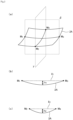
- the heat dissipation member 1 is plate-shaped.
- a main material of the heat dissipation member 1 is a metal-silicon carbide composite containing aluminum or magnesium (the details of the material will be described below together with a method of manufacturing the heat dissipation member 1).
- the heat dissipation member 1 can be made to be substantially rectangular. That is, the heat dissipation member 1 is substantially rectangular in a top view where one main surface is a top surface.
- being substantially rectangular represents that at least one of four corners of the heat dissipation member 1 may have a slightly rounded shape without being linear (of course, the four corners may be linear).
- At least one of the four corners of the heat dissipation member 1 is processed in a rounded shape, an intersection point when straight line portions of a short side and a long side of the heat dissipation member 1 in the top view are extended can be defined as "apex”.
- "the length of the short side” or “the length of the long side” of the heat dissipation member 1 can be defined by using the above-described "apex" as a starting point or an end point.
- the lengths of the heat dissipation member 1 are, for example, about in a range of 40 mm ⁇ 90 mm to 250 mm ⁇ 140 mm.
- the thickness of the heat dissipation member 1 is, for example, 2 mm or more and 6 mm or less and preferably 3 mm or more and 5 mm or less. If the thickness of the heat dissipation member 1 is not uniform, it is preferable that the thickness of at least a center-of-gravity portion of the heat dissipation member 1 is in the above-described range.
- FIG. 1 (b) of Fig. 1 is a cross-sectional view of the heat dissipation member 1 taken along a surface ⁇ of (a) of Fig. 1 .
- the plate-shaped heat dissipation member 1 includes two main surfaces (one main surface will be referred to as “main surface 2A", and the other main surface will be referred to as “main surface 2B”) .
- the main surface 2A is a surface to be joined to a heat dissipation fin or the like
- the main surface 2B is a surface to be connected to a power element or the like.
- the main surface 2A is curved to be convex in an outward direction instead of in an inward direction of the heat dissipation member 1.
- the main surface 2A is curved to be convex in the outward direction as a whole and does not include a portion that is partially concave.
- f 2 is less than f 1 by 10 um or more.
- the degree of curve on the main surface 2A side and the degree of curve on the main surface 2B side are substantially the same in many cases. Accordingly, when the main surface 2B side is connected to a component such as a power element, alignment may be difficult or the connection of the component itself may be difficult.
- f 1 (representing the degree of curve of the main surface 2A) is relatively large, and f 2 (representing the degree of curve of the main surface 2B) is relatively small.
- the joinability between the heat dissipation member 1 and a heat dissipation fin or the like can be sufficiently obtained, and thus sufficient heat dissipation can be obtained.
- the alignment or the connection of the component can be made to be easier as compared to the heat dissipation member in the related art.
- the flatness defined by JIS B 0621 can be defined as a minimum interval between two planes that are geometrically parallel to each other when a planar body is interposed between the two planes.
- Examples of a measuring device of the flatness f 1 and the flatness f 2 include a device VR-3000 manufactured by Keyence Corporation.
- f 1 is measured for the main surface 2A as a whole. It is noted that the main surface 2A as a whole may not be included in a field of view of the measuring device depending on the size of the heat dissipation member 1. In this case, f 1 is measured such that the center (geometric center of gravity) of the main surface 2A in a top view matches the center of the field of view of the measuring device. At this time, it is preferable that a long side of the main surface 2A that is substantially rectangular and a long side of the field of view (the field of view of the measuring device for the flatness is typically rectangular) are parallel to each other. The same is applicable to the measurement of f 2 .
- the heat dissipation member 1 will be described in more detail.
- f 2 may be less than f 1 by 10 um or more, it is preferable that f 2 is less than f 1 by 50 um or more, and it is more preferable that f 2 is less than f 1 by 100 um or more.
- the difference (f 1 - f 2 ) between f 1 and f 2 is preferably 600 um or less, more preferably 500 um or less, and still more preferably 400 um or less.
- f 1 itself is preferably 100 um or more and 700 um or less and more preferably 200 um or more and 600 um or less.
- the value of f 2 itself is preferably 300 um or less, more preferably 250 um or less, still more preferably 200 um or less, and still more preferably 100 um or less.
- the lower limit value of f 2 may be, for example, 0. In addition, in another example, the lower limit value f 2 may be 50 um or more.
- the heat dissipation member 1 can be fixed to a heat dissipation fin or the like with good connectivity with an appropriate (not excessively high) fastening force. This leads to further improvement in heat dissipation, a reduction in cracking caused by an excessive force, and the like.
- the main surface 2B may be curved to be convex in the outward direction of the heat dissipation member 1. Conversely, that is, the main surface 2B may be curved to be concave in the outward direction of the heat dissipation member 1. From the viewpoint of the curve and the like of the heat dissipation member 1 during the manufacturing of a power device as a final product, it is preferable that the main surface 2B is curved to be concave in the outward direction of the heat dissipation member 1.
- the main surface 2B is curved to be concave in the outward direction of the heat dissipation member 1, and when the degree of the curve is represented by the flatness, the flatness is preferably 300 pm or less, more preferably 250 um or less, still more preferably 200 pm or less, and still more preferably 100 pm or less.
- the main surface 2B may be curved to be convex in the outward direction of the heat dissipation member 1.
- the degree of curve represented by f 2 is less than f 1 by 10 um or more, a problem in the connection to a power element or the like can be suppressed.
- the main surface 2A and/or the main surface 2B may be a metal-silicon carbide composite containing aluminum or magnesium.
- the main surface 2A and/or the main surface 2B may be a metal layer.
- the main surface 2A and/or the main surface 2B is a surface metal layer containing aluminum or magnesium.
- a portion of the heat dissipation member 1 other than the surface metal layer can be made to be the metal-silicon carbide composite or the like.
- a metal in the metal surface layer is the same as the metal in the metal-silicon carbide composite. The reason for this is a reason relating to the manufacturing of the heat dissipation member 1 (the method of manufacturing the heat dissipation member 1 will be described below) .
- a plating layer is provided on the outside further than the above-described surface metal layer. Since a solder is used for the connection to a power element or the like, the plating layer can improve the wettability of the solder.
- the plating layer can be made to be, for example, a Ni-containing plating layer.
- the average thickness of the surface metal layer is not particularly limited and is, for example, 10 um or more and 300 um or less and preferably 30 um or more and 150 um or less.
- the average thickness of the plating layer is not particularly limited and is, for example, 3 um or more and 15 um or less and preferably 4 um or more and 10 um or less.
- the value of f 1 or f 2 in principle, the value of the flatness of the outermost surface of the heat dissipation member 1 is adopted.
- the flatness of both main surfaces of the plate-shaped metal-silicon carbide composite can be measured to obtain the value of f 1 or f 2 .
- the flatness of the surface of the surface metal layer or the plating layer as the outermost surface can be measured to obtain the value of f 1 or f 2 .
- the performance such as heat dissipation can be further improved.
- an average length RS m of roughness curve elements of the main surface 2A is designed to be 50 pm or more and 250 pm or less, and it is more preferable that the average length RS m is designed to be 70 um or more and 160 um or less.
- the joinability to a heat dissipation fin or the like can be further improved, and the heat dissipation can be further improved.
- the detailed mechanism or the like is not clear but is presumed to be that, by appropriately designing RS m , micro gaps between the heat dissipation member 1 and the heat dissipation fin can be reduced and the joinability can be further improved.
- an average length RS m of roughness curve elements of the main surface 2B is designed to be 50 pm or more and 200 pm or less, and it is more preferable that the average length RS m is designed to be 70 um or more and 160 um or less.
- Fig. 2 is a diagram showing a configuration of the main surface 2A of the heat dissipation member 1.
- FIG. 2 is a diagram showing only the main surface 2A of the heat dissipation member 1, (b) of Fig. 2 is a cross-sectional view of the main surface 2A taken along a cross-section ⁇ of (a) of Fig. 2, and (c) of Fig. 2 is a cross-sectional view of the main surface 2A taken along a cross-section ⁇ of (a) of Fig. 2 .
- auxiliary lines and the like are shown for the following description.
- the length of a long side of the rectangular heat dissipation member 1 is represented by a
- the length of a short side of the heat dissipation member 1 is represented by b
- a straight line connecting middle points (represented by M 1 and M 3 in the drawing) of two short sides of the main surface 2A is represented by l 1
- a straight line connecting middle points (represented by M 2 and M 4 in the drawing) of two long sides of the main surface 2A is represented by l 2 .
- h 1 a maximum distance between a point on a curve of the main surface 2A and l 1 in a cross-sectional view of the heat dissipation member 1 showing the cross-section ⁇ including l 1 and substantially perpendicular to the main surface 2A
- h 2 a maximum distance between a point on a curve of the main surface 2A and l 2 in a cross-sectional view of the heat dissipation member 1 showing the cross-section ⁇ including l 2 and substantially perpendicular to the main surface 2A
- the heat dissipation member 1 is designed such that h 1 /a ⁇ h 2 /b.
- the value of (h 1 /a) / (h 2 /b) is preferably 1.00 or higher and 1.9 or lower and more preferably 1.07 or higher and 1.6 or lower.
- h 1 /a represents "the curve per unit length in a long side direction" of the heat dissipation member 1.
- h 2 /b represents "the curve per unit length in a short side direction" of the heat dissipation member 1.
- h 1 /a ⁇ h 2 /b can be interpreted to be that "the degree of curve" in the long side direction is the same as or higher than that in the short side direction in addition to the fact that a long side is longer than a short side.
- the curved heat dissipation member 1 when the curved heat dissipation member 1 is pressed against and joined to another component using a screw, the rectangular (oblong) heat dissipation member 1 is more likely to be deformed (likely to be bent) in the long side direction than in the short side direction. Accordingly, it is presumed that, by designing "the degree of curve" in the long side direction to be higher than that in the short side direction, the heat dissipation member 1 as a whole can be easily flattened even without applying an excessive force (even when the screwing force is relatively low) . In addition, it is presumed that, by designing the screwing force to be relatively low, cracking in the vicinity of the screw can be suppressed.
- the heat dissipation member 1 includes a hole for screwing (not shown in Figs. 1 and 2 ).
- the hole for screwing is provided in peripheral portions of four corners of the heat dissipation member 1.
- a hole may be provided in the vicinity of the middle point of the long side in the peripheral portion of the heat dissipation member 1.
- the diameter of the hole can be made to be, for example, about 5 mm or more and 9 mm or less.
- a unit that joins the heat dissipation member 1 to another component is not limited to a screw.
- the heat dissipation member 1 may be joined to another component using a dedicated jig capable of attaching the heat dissipation member 1 to another component.
- a method of manufacturing the heat dissipation member according to the embodiment is not particularly limited and can be manufactured appropriately using a well-known method.
- the heat dissipation member according to the embodiment can be manufactured through steps including: (i) a step of preparing a plate-shaped metal-silicon carbide composite containing aluminum or magnesium; and(ii) a step of mechanically processing (for example, grinding or cutting) a part of at least one surface of the metal-silicon carbide composite to provide the main surface 2A.
- the heat dissipation member according to the embodiment includes the metal-silicon carbide composite containing aluminum or magnesium.
- a method that is preferably used for manufacturing the metal-silicon carbide composite is a high-pressure forging method of impregnating a porous body with a metal at a high pressure. More specifically, squeeze casting or die casting can be adopted. In the high-pressure forging method, a porous silicon carbide body (preform) is charged into a high-pressure container, and is impregnated with molten metal containing aluminum or magnesium at a high pressure to obtain a composite.
- squeeze casting is more preferable due to the reason that a large number of products can be stably manufactured.
- the manufacturing method using squeeze casting will be described.
- the heat dissipation member according to the embodiment can be manufactured through the following steps:
- Step 1 (Step 1) to (Step 4) will be described in more detail.
- a method of manufacturing the porous silicon carbide body (SiC preform) in (Step 1) is not particularly limited, and the porous silicon carbide body can be manufactured using a well-known method.
- the porous silicon carbide body can be manufactured by adding silica, alumina, or the like as a binder to silicon carbide (SiC) powder as a raw material, mixing the components, molding and calcinating the mixture at 800°C or higher.
- a molding method is not particularly limited, press molding, extrusion molding, cast molding, or the like can be used.
- a binder for shape retention can be used in combination.
- the metal-silicon carbide composite obtained by impregnating the porous silicon carbide body with a metal containing aluminum or magnesium are thermal conductivity and a thermal expansion coefficient. It is preferable that the SiC content in the porous silicon carbide body is high because the thermal conductivity is high and the thermal expansion coefficient is low. It is noted that, when the content is excessively high, the porous silicon carbide body is not sufficiently impregnated with an aluminum alloy.
- the relative density of the SiC preform is preferably in a range of 55% or higher and 75% or lower.
- the bending strength of the porous silicon carbide body (SiC preform) is preferably 3 MPa or higher in order to prevent fracturing during handling or impregnation.
- the average particle size can be measured by calculating the average value of particle sizes of 1000 particles using a scanning electron microscope (for example, "JSM-T200 model", manufactured by JEOL Ltd.) and an image analyzer (for example, manufactured by Nippon Avionics Co., Ltd.).
- the relative density can be measured using the Archimedes method.
- the particle size of the SiC powder as a raw material of the porous silicon carbide body (SiC preform) is adjusted by appropriately using coarse powder and fine powder in combination.
- the strength of the porous silicon carbide body (SiC preform) and the thermal conductivity of the heat dissipation member that is finally obtained can be improved at a high level.
- mixed powder obtained by mixing (i) SiC coarse powder having an average particle size of 40 um or more and 150 um or less and (ii) SiC fine powder having an average particle size of 5 pm or more and 15 um or less is suitable.
- the amount of (i) is 40 mass% or higher and 80 mass% or lower, and the amount of (ii) is preferably 20 mass% or higher and 60 mass% or lower.
- the porous silicon carbide body (SiC preform) is obtained by, for example, degreasing and calcinating a compact of a mixture obtained by adding the binder to the SiC powder.
- the calcination temperature is 800°C or higher, a porous silicon carbide body (SiC preform) having a bending strength of 3 MPa or higher is likely to be obtained irrespective of the atmosphere during the calcination.
- the calcination is performed at a temperature exceeding 1100°C in an oxidizing atmosphere, the oxidation of SiC is promoted, and the thermal conductivity of the metal-silicon carbide composite may decrease. Accordingly, it is preferable that the calcination is performed at a temperature of 1100°C or lower in the oxidizing atmosphere.
- the calcination time may be appropriately determined depending on conditions such as the size of the porous silicon carbide body (SiC preform), the amount of raw materials charged into a calcination furnace, or the calcination atmosphere.
- porous silicon carbide body SiC preform
- a change in curve caused by drying can be prevented by performing drying one by one or by performing drying using a spacer such as carbon having the same shape as the preform shape between SiC preforms.
- a shape change caused by a change in internal structure can be prevented.
- Step 2 at least a single surface of the porous silicon carbide body (SiC preform) is processed in a convex curved shape toward the outside, for example, a cutting and grinding tool such as a lathe.
- a cutting and grinding tool such as a lathe.
- both surfaces of the porous silicon carbide body may be processed instead of the single surface. That is, both surfaces of the porous silicon carbide body (SiC preform) may be processed such that, in the finally obtained heat dissipation member, f 2 is less than f 1 by 10 um or more and the values of f 1 and f 2 are desired values.
- the porous silicon carbide body (SiC preform) can be impregnated with a metal containing aluminum or magnesium using a high-pressure forging method to prepare a metal-silicon carbide composite including a composite portion and a surface metal layer, the composite portion containing silicon carbide and a metal, and the surface metal layer being provided on an outer surface of the composite portion.
- Examples of a method of obtaining the metal-silicon carbide composite by impregnating the porous silicon carbide body (SiC preform) with the metal (alloy) containing aluminum or magnesium include the following method.
- the porous silicon carbide body (SiC preform) is put into a mold, and one or more kinds among fibers, spherical particles, and crushed particles formed of alumina or silica are disposed to be in direct contact with on both plate surfaces of the mold. As a result, one block is obtained.
- This block is preheated to 500°C or higher and 650°C or lower, and one or two or more blocks are disposed in a high-pressure container.
- molten metal containing aluminum or magnesium is pressurized at a pressure of 30 MPa or higher, and the metal is impregnated into voids of the porous silicon carbide body (SiC preform).
- the metal-silicon carbide composite including a composite portion and a surface metal layer is obtained, the composite portion containing silicon carbide and a metal, and the surface metal layer being provided on an outer surface of the composite portion.
- the melting point of the metal (typically, the alloy containing aluminum or magnesium) in the metal-silicon carbide composite is as low as possible so as to sufficiently permeate into the voids of the preform during the impregnation.
- an aluminum alloy containing 7 mass% or higher and 25 mass% or lower of silicon is preferable. Further, it is preferable that 0.2 mass% or higher and 5 mass% or lower of magnesium is contained from the viewpoint that the binding between the silicon carbide powder and the metal portion becomes more strong.
- Metal components in the aluminum alloy other than aluminum, silicon, and magnesium are not particularly limited within a range where characteristics do not change extremely. For example, copper may be included.
- the aluminum alloy for example, AC4C, AC4CH, or ADC12 that is an alloy for forging can be preferably used.
- an annealing treatment may be performed after the preparation of the metal-silicon carbide composite. It is preferable that the annealing treatment that is performed in order to remove strain is performed at a temperature of 400°C or higher and 550°C or lower for 10 minutes or longer and 5 hours or shorter.
- the annealing temperature is 400°C or higher, strain in the composite is sufficiently released, and a significant change in curve in the annealing treatment step after mechanical processing can be suppressed.
- the annealing temperature is 550°C or lower, the aluminum alloy used for the impregnation can be prevented from melting.
- the annealing time is 10 minutes or longer, strain in the composite is sufficiently released, and a significant change in curve in the annealing treatment step for removing processing strain after mechanical processing can be suppressed.
- the annealing time is 5 hours or shorter from the viewpoint of mass productivity or the like.
- one or more kinds among fibers, spherical particles, and crushed particles formed of alumina or silica can be disposed to be in direct contact with the surface of the porous silicon carbide body (SiC preform) .
- SiC preform porous silicon carbide body
- the content of the material including one or more kinds among fibers, spherical particles, and crushed particles formed of alumina or silica in the surface metal layer is preferably 0.1 mass% or higher and 5 mass% or lower and more preferably 0.3 mass% or higher and 2 mass% or lower with respect to the mass of the metal-silicon carbide composite.
- the content is 0.1 mass% or higher, it is easy to control the thickness of the aluminum layer, and a significant change in curved shape caused by the annealing treatment after processing can be suppressed.
- the content is 5 mass% or lower, the aluminum alloy layer is not excessively hard, and general mechanical processing can be easily performed.
- the thickness of the surface metal layer provided on the surface of the metal-silicon carbide composite may be appropriately adjusted such that the difference in thickness between the front and rear surface metal layers after processing is not large irrespective of whether only a heat dissipation surface (corresponding to the main surface 2A in the heat dissipation member 1) or both surfaces are mechanically processed in (Step 4). After the adjustment, the above-described inorganic fiber can be appropriately used.
- the average thickness of the metal layer on the circuit board mounting surface side (corresponding to the main surface 2B in the heat dissipation member 1) is preferably 10 pm or more and 300 pm or less.
- the average thickness of the metal-containing layer having a smaller thickness is less than 50% with respect to the average thickness of the metal-containing layer having a larger thickness.
- the difference in average thickness between the metal-containing layers of both of the surfaces is adjusted to be preferably less than 40% and more preferably less than 30% with respect to the average thickness of the metal-containing layer of the heat dissipation surface.
- the reason for this is that a change in curved state depending on a difference in thermal expansion coefficient between the metal-containing layers of both of the surfaces can be suppressed.
- Step 4 at least the surface metal layer on the surface side processed in a convex curved shape in the metal-silicon carbide composite is mechanically processed and, in some cases, is further annealed to obtain a heat dissipation member in which f 2 is less than f 1 by 10 um or more.
- a tool such as a lathe capable of accurate scraping (for example, grinding or cutting).
- the metal-silicon carbide composite is heated at about 400°C to 550°C using a muffle furnace and is annealed for about 2 hours to 6 hours.
- a heat dissipation member in which f 1 , f 2 , and the like have desired numerical values can be obtained.
- a heat dissipation member having the desired values of f 1 , f 2 , h 1 /a, h 2 /b, and the like can be obtained. That is, a heat dissipation member having more satisfactory heat dissipation properties, reliability, and the like can be obtained.
- a heat treatment such as "annealing” that is performed in (Step 1) to (Step 4), typically, the metal-silicon carbide composite or the heat dissipation member is deformed as a whole. That is, even when a curved shape is formed on only the heat dissipation surface of the metal-silicon carbide composite by grinding, cutting or the like, typically, a certain degree of curve is formed on the surface opposite to the heat dissipation surface through a heat treatment such as annealing (that is, f 2 is typically a value other than 0) .
- the degree of deformation by the heat treatment such as annealing can be estimated quantitatively to some extent, for example, by performing a preliminary experiment several times.
- the total average thickness of the metal-containing layers of both of the surfaces after mechanical processing is preferably 500 um or less and more preferably 300 um or less.
- the thermal expansion of the heat dissipation member as a whole is suppressed to be relatively small.
- cracking caused by a difference in thermal expansion coefficient between the heat dissipation member and a power element or the like connected to an upper surface thereof can be suppressed.
- the method of manufacturing the heat dissipation member according to the embodiment is not limited to the above-described configuration.
- the surface metal layer is an optional configuration. Therefore, in (Step 3), the surface metal layer does not need to be formed.
- the removal of (Step 2) may be considered. That is, it may be considered to obtain a heat dissipation member having a desired curve or flatness by performing necessary mechanical processing in (Step 4) without performing processing into a curved shape at the stage of the porous silicon carbide body (SiC preform) before impregnating the porous silicon carbide body with the metal.
- the mechanical processing can be performed more easily before the impregnation with the metal than after the impregnation with the metal. Therefore, from the viewpoint of, for example, reducing manufacturing costs, it is preferable to form the curved shape to some extent at the stage of (Step 2).
- the removal of (Step 4) may be considered. That is, mechanical processing in (Step 4) may be unnecessary by performing curve processing with sufficient accuracy at the stage of (Step 2) to provide desired curve to the mold used for the impregnation in (Step 3) .
- mechanical processing in (Step 4) may be unnecessary by performing curve processing with sufficient accuracy at the stage of (Step 2) to provide desired curve to the mold used for the impregnation in (Step 3) .
- the method of manufacturing the heat dissipation member according to the embodiment may include another step other than the above-described steps.
- a step of providing the hole for screwing may be provided.
- the hole for screwing for joining to another component may be provided in the metal-silicon carbide composite by mechanical processing or the like.
- a step of polishing or blasting the surface of the heat dissipation member may be performed after (Step 4).
- the above-described average length RS m of the roughness curve elements can be appropriately adjusted.
- a specific method of the polishing treatment or the blasting treatment a well-known method can be appropriately used.
- a plating layer may be provided by performing a plating step after (Step 4).
- the plating layer can be provided on the surface of the heat dissipation member using a well-known method of electroless Ni-P plating or Ni-B plating. A preferable thickness and the like of the plating layer are as described above.
- main surface 2A is a surface to be joined to a heat dissipation fin or the like and is curved to be convex in the outward direction instead of the inward direction of the heat dissipation member.
- main surface 2B is a surface to be connected to a component such as a power element.
- silicon carbide powder A, silicon carbide powder B, and silica sol described below were mixed with each other using a stirring mixer for 30 minutes to obtain a mixture.
- the obtained mixture was put into a mold and was pressed at a pressure of 10 MPa. As a result, a flat compact having a dimension of 185 mm ⁇ 135 mm ⁇ 5.5 mm was obtained.
- the obtained compact was calcinated in air at a temperature of 900°C for 2 hours to obtain a porous silicon carbide body having a relative density (bulk density) of 65 vol%.
- a surface of the porous silicon carbide body forming the main surface 2B of the heat dissipation member after completion was processed with a surface grinding machine.
- the thickness of the center of the porous silicon carbide body was adjusted to be 4.8 mm.
- Alumina fibers manufactured by Tanaka Paper Co., Ltd., purity: 97%, sheet form
- both surfaces were interposed between carbon-coated stainless steel sheets having a dimension of 210 mm ⁇ 160 mm ⁇ 0.8 mm, and 30 bodies were laminated.
- iron sheets having a thickness of 6 mm were disposed on both sides and were fastened six M10 bolts lined to each other using a torque wrench such that the fastening torque in a planar direction was 3 Nm. As a result, one block was obtained.
- the integrated block was preheated to 620°C in an electric furnace and subsequently was put into a press mold having an inner diameter of 400 mm ⁇ that was heated in advance.
- Molten aluminum alloy containing 12 mass% of silicon and 1.0 mass% of magnesium was poured into the press mold, and the mold was pressurized at a pressure of 100 MPa for 20 minutes.
- the porous silicon carbide body was impregnated with the aluminum alloy.
- the unit After completion of the impregnation, the unit was cooled to 25°C and was cut along a shape of the stainless steel sheets using a wet bandsaw to remove the interposed stainless steel sheets. Further, next, in order to remove strain during the impregnation, an annealing treatment was performed at a temperature of 500°C for 3 hours.
- the outer periphery of the obtained aluminum-silicon carbide composite was processed with an NC lathe such that the lengths were 190 mm ⁇ 140 mm.
- an NC lathe such that the lengths were 190 mm ⁇ 140 mm.
- through holes having a diameter of 7 mm were formed at eight positions, and countersink holes having a diameter ⁇ of 10-4 mm were formed at four positions.
- an annealing treatment was performed at a temperature of 500°C for 4 hours in a muffle furnace. As a result, processing strain was removed.
- the aluminum-silicon carbide composite was blasted and cleaned with alumina abrasive grains under conditions of pressure: 0.4 MPa, transport speed: 1.0 m/min.
- electroless Ni-P plating and Ni-B plating were performed.
- a plating layer having a thickness of 8 um (Ni-P: 6 um, Ni-B: 2 um) was formed on the surface of the composite.
- the flatness values of the main surface 2A and the main surface 2B of the obtained heat dissipation member were measured using a device VR-3000 (manufactured by Keyence Corporation) to obtain f 1 and f 2 .
- the main surface 2A and the main surface 2B were not included in the field of view of the device. Therefore, a range of 190 mm ⁇ 100 mm was measured such that the center (geometric center of gravity) of the main surface 2A/the main surface 2B in a top view matched the center of the field of view of the measuring device.
- the average length RSm of roughness curve elements in the main surface 2A and the main surface 2B were measured using a device SJ-310 (manufactured by Mitutoyo Corporation) according to ISO4287-1997.
- heat dissipation members were prepared through the same steps as those of Example 1, except that the length of a long side and a short side of the heat dissipation member, the processing R in (Formation of Porous Silicon Carbide Body), and the processing R in (Treatment after Impregnation) and the like were changed. Next, various numerical values were measured using the same methods as those of Example 1.
- Heat dissipation members were prepared through the same steps as those of Example 1, except that a surface of the porous silicon carbide body forming the main surface 2B of the heat dissipation member after completion was not processed with a surface grinding machine in (Formation of Porous Silicon Carbide Body), and the processing R in (Formation of Porous Silicon Carbide Body), the processing R in (Treatment after Impregnation) and the like were changed. Next, various numerical values were measured using the same methods as those of Example 1.
- a ceramic substrate (substrate having both surfaces where a metal layer such as copper or aluminum was provided) was soldered to six specific positions of the main surface 2B among two main surfaces of the heat dissipation member according to each of Examples and Comparative Examples. As a result, a substrate for a simulated power module was obtained.
- the obtained simulated power module was investigated for whether or not a defect causing a problem relating to manufacturing was present.
- the manufacturing stability for example, yield
- the plate-shaped heat dissipation member having the characteristics such as the satisfaction of the specific relationship between the flatness values of the two main surfaces.
- the heat dissipation member according to each of Examples 1 to 12 was joined to a heat dissipation fin with a screw, and adhesion between the heat dissipation member and the heat dissipation fin, heat dissipation, and the like were evaluated. As a result, the adhesion and the heat dissipation were excellent.
Landscapes
- Chemical & Material Sciences (AREA)
- Engineering & Computer Science (AREA)
- Ceramic Engineering (AREA)
- Materials Engineering (AREA)
- Organic Chemistry (AREA)
- Structural Engineering (AREA)
- Physics & Mathematics (AREA)
- Microelectronics & Electronic Packaging (AREA)
- Thermal Sciences (AREA)
- Mechanical Engineering (AREA)
- Inorganic Chemistry (AREA)
- General Physics & Mathematics (AREA)
- Condensed Matter Physics & Semiconductors (AREA)
- Computer Hardware Design (AREA)
- Power Engineering (AREA)
- Manufacturing & Machinery (AREA)
- General Engineering & Computer Science (AREA)
- Metallurgy (AREA)
- Chemical Kinetics & Catalysis (AREA)
- General Chemical & Material Sciences (AREA)
- Crystallography & Structural Chemistry (AREA)
- Cooling Or The Like Of Semiconductors Or Solid State Devices (AREA)
Description
- The present invention relates to a heat dissipation member and a method of manufacturing the same. More specifically, the present invention relates to a plate-shaped heat dissipation member including a metal-silicon carbide composite containing aluminum or magnesium and a method of manufacturing the same.
- Recently, as a heat dissipation component for a power module in an electric vehicle or an electric railway, a heat dissipation member formed of a metal-silicon carbide composite has been used instead of copper in the related art.
- As the metal of the metal-silicon carbide composite, aluminum or an alloy thereof is used frequently.
- In many cases, the heat dissipation member is used in a state where it is joined to another component (for example, a heat dissipation fin or a heat dissipation unit, and characteristics of the junction portion are important.
- For example, when the heat dissipation member is joined to a heat dissipation fin or a heat dissipation unit, in general, the heat dissipation member is screwed and fixed to the heat dissipation fin, the heat dissipation unit, or the like using a hole provided in a peripheral portion of the heat dissipation member. However, when a surface of the heat dissipation member in contact with the heat dissipation fin or the like is concave or when many fine uneven portions are present, a gap may be formed between the heat dissipation member and the heat dissipation fin or the like, and there is a problem in that heat transference deteriorates.
- In consideration of the above-described problem, some heat dissipation members are disclosed in which a surface joined to a heat dissipation fin or the like is curved to be convex to prevent the formation of a gap between the heat dissipation member and the heat dissipation fin or the like as far as possible.
- The reason for this is follows. As described above, typically, the heat dissipation member is used in a state where it is fixed to the heat dissipation fin or the like with a fixing member such as a screw. Therefore, by forming the surface joined to the heat dissipation fin or the like to be curved to be convex, the joined surface is "appropriately flat" during fixing with the fixing member, and joinability (adhesion) to the heat dissipation fin or the like is improved.
- For example,
Patent Document 1 discloses a plate-shaped silicon carbide composite in which a porous silicon carbide compact is impregnated with a metal containing aluminum as a main component, four or more hole portions for screwing a convex surface of the plate-shaped composite to another heat dissipation component are provided in a surface of the plate-shaped composite, and a relationship between a warpage (Cx: um) per 10 cm in a hole-to-hole direction (X direction) and a warpage (Cy: um) per 10 cm in a direction (Y direction) perpendicular thereto is 50 ≤ Cx ≤ 250 and -50 ≤ Cy ≤ 200 (excluding Cy = 0). - In another example, Patent Document 2 discloses a plate-shaped silicon carbide composite in which a porous silicon carbide compact is impregnated with a metal containing aluminum as a main component, and a warpage per 10 cm of a main surface of the composite is 250 um or less.
-
US 2013/0328184 A1 discloses a plate-shaped dissipation member including a metal-silicon carbide composite containing magnesium capable of efficiently dissipating heat to an object with particular warpage amount.EP 3 104 406 A1 discloses a high-thermal-conductivity silicon carbide complex material with particular plate thicknesses. -
- [Patent Document 1]
Japanese Patent Application No. 3468358 - [Patent Document 2] Pamphlet of International Publication No.
WO2015/115649 - As described above, it is known that, (1) by manufacturing a curved heat dissipation member first and then (2) "flattening" the curve with a force of a screw during joining to the heat dissipation fin or the like, joinability between the heat dissipation member and the heat dissipation fin or the like is improved and further heat dissipation is improved.
- However, typically, a surface of the heat dissipation member opposite to the surface in contact with the heat dissipation fin or the like is connected to a component such as a power element. Therefore, when the component is connected to the curved heat dissipation member, in particular, in a mass-production stage, alignment may be difficult or the connection of the component itself may be difficult.
- That is, when the component is connected to a single surface of the curved heat dissipation member to manufacture a power module or the like, there is a room for improvement from the viewpoint of manufacturing stability (for example, yield).
- The present invention has been made under these circumstances.
- One object of the present invention is to improve manufacturing stability (for example, yield) when a component is connected to a single surface of a curved heat dissipation member to manufacture a power module or the like.
- The present inventors conducted a thorough investigation in order to achieve the above-described object. As a result, it was found that flatness or the like of two main surfaces of a plate-shaped heat dissipation member defined by JIS B 0621 has a close relationship with the achievement of the object. Based on this finding, the present invention provided below was completed.
- According to the present invention,
- there is provided a plate-shaped heat dissipation member including a metal-silicon carbide composite containing aluminum or magnesium,
- in which at least one of two main surfaces of the heat dissipation member is curved to be convex in an outward direction of the heat dissipation member, and
- when a flatness of the one main surface defined by JIS B 0621 is represented by f1 and a flatness of the other main surface different from the one main surface defined by JIS B 0621 is represented by f2, f2 is less than f1 by 10 um or more, wherein JIS B 0621 defines the flatness as a minimum interval between two planes that are geometrically parallel to each other when a planar body is interposed between the two planes.
- In addition, according to the present invention,
there is provided a method of manufacturing the above-described heat dissipation member, the method including: - a step of preparing a plate-shaped metal-silicon carbide composite containing aluminum or magnesium; and
- a step of mechanically processing a part of at least one surface of the composite to provide the one main surface.
- According to the present invention, manufacturing stability (for example, yield) can be improved when a component is connected to a single surface of a curved heat dissipation member to manufacture a power module or the like.
- The above-described object, other objects, characteristics, and advantageous effects will be further clarified using preferred embodiments described below and the accompanying drawings below.
-
Fig. 1 is a schematic diagram showing a heat dissipation member according to an embodiment, in which (a) is a bird's eye view showing the heat dissipation member according to the embodiment and (b) is a cross-sectional view of the heat dissipation member taken along a cross-section α of (a). -
Fig. 2 is a diagram particularly showing at least one of two main surfaces of the heat dissipation member according to the embodiment, in which (a) shows only one of two main surfaces of the heat dissipation member, (b) is a cross-sectional view of the one main surface taken along a cross-section β of (a), and (c) is a cross-sectional view of the one main surface taken along a cross-section γ of (a). - Hereinafter, embodiments of the present invention will be described in detail with reference to the drawings.
- In all the drawings, the same components are represented by the same reference numerals, and the description thereof will not be repeated.
- In order to avoid complication, (i) when a plurality of the same components are present on the same drawing, there may be a case where the reference numeral is given to only one component without giving the reference numeral to all the components; and (ii) in the drawings after
Fig. 2 , there may be a case where the reference numeral is not given again to the same components as those ofFig. 1 . - All the drawings are merely illustrative. The shapes, a dimensional ratio, and the like of each of members in the drawings do not necessarily correspond to those of an actual product. In particular, for easy understanding of the description, a shape or a dimensional ratio may be shown in an exaggerated manner. In particular, in each of the drawings, the size of "curve" is more exaggerated than the actual product.
- In the present specification, unless explicitly specified otherwise, the term "substantially" in the present specification is intended to include a range defined in consideration of manufacturing tolerances, assembly variations, and the like.
- Unless specified otherwise, a value measured at room temperature (23°C) can be adopted as a value that is variable depending on temperatures among various numerical values (in particular, measured values) in the present specification.
-
- (a) of
Fig. 1 is a bird's eye view showing a heat dissipation member (heat dissipation member 1) according to an embodiment. - The
heat dissipation member 1 is plate-shaped. - A main material of the
heat dissipation member 1 is a metal-silicon carbide composite containing aluminum or magnesium (the details of the material will be described below together with a method of manufacturing the heat dissipation member 1). - Typically, the
heat dissipation member 1 can be made to be substantially rectangular. That is, theheat dissipation member 1 is substantially rectangular in a top view where one main surface is a top surface. - Here, "being substantially rectangular" represents that at least one of four corners of the
heat dissipation member 1 may have a slightly rounded shape without being linear (of course, the four corners may be linear). - Supplementarily, at least one of the four corners of the
heat dissipation member 1 is processed in a rounded shape, an intersection point when straight line portions of a short side and a long side of theheat dissipation member 1 in the top view are extended can be defined as "apex". In addition, at this time, "the length of the short side" or "the length of the long side" of theheat dissipation member 1 can be defined by using the above-described "apex" as a starting point or an end point. - The lengths of the
heat dissipation member 1 are, for example, about in a range of 40 mm × 90 mm to 250 mm × 140 mm. - The thickness of the
heat dissipation member 1 is, for example, 2 mm or more and 6 mm or less and preferably 3 mm or more and 5 mm or less. If the thickness of theheat dissipation member 1 is not uniform, it is preferable that the thickness of at least a center-of-gravity portion of theheat dissipation member 1 is in the above-described range. - (b) of
Fig. 1 is a cross-sectional view of theheat dissipation member 1 taken along a surface α of (a) ofFig. 1 . - The plate-shaped
heat dissipation member 1 includes two main surfaces (one main surface will be referred to as "main surface 2A", and the other main surface will be referred to as "main surface 2B") . Typically, themain surface 2A is a surface to be joined to a heat dissipation fin or the like, and themain surface 2B is a surface to be connected to a power element or the like. - In the
heat dissipation member 1, in particular, at least themain surface 2A is curved to be convex in an outward direction instead of in an inward direction of theheat dissipation member 1. Typically, themain surface 2A is curved to be convex in the outward direction as a whole and does not include a portion that is partially concave. - When a flatness of the
main surface 2A defined by JIS B 0621 is represented by f1 and a flatness of themain surface 2B defined by JIS B 0621 is represented by f2, f2 is less than f1 by 10 um or more. - In a curved heat dissipation member in the related art, the degree of curve on the
main surface 2A side and the degree of curve on themain surface 2B side are substantially the same in many cases. Accordingly, when themain surface 2B side is connected to a component such as a power element, alignment may be difficult or the connection of the component itself may be difficult. - On the other hand, in the
heat dissipation member 1 ofFig. 1 , f1 (representing the degree of curve of themain surface 2A) is relatively large, and f2 (representing the degree of curve of themain surface 2B) is relatively small. As a result, on themain surface 2A side, the joinability between theheat dissipation member 1 and a heat dissipation fin or the like can be sufficiently obtained, and thus sufficient heat dissipation can be obtained. Accordingly, on themain surface 2B side, the alignment or the connection of the component can be made to be easier as compared to the heat dissipation member in the related art. - The flatness defined by JIS B 0621 can be defined as a minimum interval between two planes that are geometrically parallel to each other when a planar body is interposed between the two planes.
- Examples of a measuring device of the flatness f1 and the flatness f2 include a device VR-3000 manufactured by Keyence Corporation.
- In addition, it is preferable that f1 is measured for the
main surface 2A as a whole. It is noted that themain surface 2A as a whole may not be included in a field of view of the measuring device depending on the size of theheat dissipation member 1. In this case, f1 is measured such that the center (geometric center of gravity) of themain surface 2A in a top view matches the center of the field of view of the measuring device. At this time, it is preferable that a long side of themain surface 2A that is substantially rectangular and a long side of the field of view (the field of view of the measuring device for the flatness is typically rectangular) are parallel to each other. The same is applicable to the measurement of f2. - The
heat dissipation member 1 will be described in more detail. - In the
heat dissipation member 1, f2 may be less than f1 by 10 um or more, it is preferable that f2 is less than f1 by 50 um or more, and it is more preferable that f2 is less than f1 by 100 um or more. - On the other hand, from the viewpoints of easy manufacturing of the
heat dissipation member 1 itself, an appropriate amount of curve, and the like, the difference (f1 - f2) between f1 and f2 is preferably 600 um or less, more preferably 500 um or less, and still more preferably 400 um or less. - The value of f1 itself is preferably 100 um or more and 700 um or less and more preferably 200 um or more and 600 um or less.
- The value of f2 itself is preferably 300 um or less, more preferably 250 um or less, still more preferably 200 um or less, and still more preferably 100 um or less. The lower limit value of f2 may be, for example, 0. In addition, in another example, the lower limit value f2 may be 50 um or more.
- It is presumed that, by appropriately designing the value of f1 itself, the
heat dissipation member 1 can be fixed to a heat dissipation fin or the like with good connectivity with an appropriate (not excessively high) fastening force. This leads to further improvement in heat dissipation, a reduction in cracking caused by an excessive force, and the like. - It is presumed that, by appropriately designing the value of f2 itself, the alignment or the connection of the component to be connected to the
main surface 2B can be made more simple. - The
main surface 2B may be curved to be convex in the outward direction of theheat dissipation member 1. Conversely, that is, themain surface 2B may be curved to be concave in the outward direction of theheat dissipation member 1. From the viewpoint of the curve and the like of theheat dissipation member 1 during the manufacturing of a power device as a final product, it is preferable that themain surface 2B is curved to be concave in the outward direction of theheat dissipation member 1. - More specifically, the
main surface 2B is curved to be concave in the outward direction of theheat dissipation member 1, and when the degree of the curve is represented by the flatness, the flatness is preferably 300 pm or less, more preferably 250 um or less, still more preferably 200 pm or less, and still more preferably 100 pm or less. - Of course, the
main surface 2B may be curved to be convex in the outward direction of theheat dissipation member 1. As long as the degree of curve represented by f2 is less than f1 by 10 um or more, a problem in the connection to a power element or the like can be suppressed. - In one aspect, the
main surface 2A and/or themain surface 2B (that is, the surface of the heat dissipation member 1) may be a metal-silicon carbide composite containing aluminum or magnesium. - In another aspect, the
main surface 2A and/or themain surface 2B (the surface of the heat dissipation member 1) may be a metal layer. For example, it is preferable that themain surface 2A and/or themain surface 2B is a surface metal layer containing aluminum or magnesium. In this case, a portion of theheat dissipation member 1 other than the surface metal layer can be made to be the metal-silicon carbide composite or the like. It is preferable that a metal in the metal surface layer is the same as the metal in the metal-silicon carbide composite. The reason for this is a reason relating to the manufacturing of the heat dissipation member 1 (the method of manufacturing theheat dissipation member 1 will be described below) . - It is preferable that a plating layer is provided on the outside further than the above-described surface metal layer. Since a solder is used for the connection to a power element or the like, the plating layer can improve the wettability of the solder.
- The plating layer can be made to be, for example, a Ni-containing plating layer.
- When the
heat dissipation member 1 includes the metal surface layer, the average thickness of the surface metal layer is not particularly limited and is, for example, 10 um or more and 300 um or less and preferably 30 um or more and 150 um or less. - When the
heat dissipation member 1 includes the plating layer, the average thickness of the plating layer is not particularly limited and is, for example, 3 um or more and 15 um or less and preferably 4 um or more and 10 um or less. - As the value of f1 or f2, in principle, the value of the flatness of the outermost surface of the
heat dissipation member 1 is adopted. - For example, when the
heat dissipation member 1 is formed of only the plate-shaped metal-silicon carbide composite, the flatness of both main surfaces of the plate-shaped metal-silicon carbide composite can be measured to obtain the value of f1 or f2. - In addition, when the outermost surface of the
heat dissipation member 1 is the surface metal layer or the plating layer, the flatness of the surface of the surface metal layer or the plating layer as the outermost surface can be measured to obtain the value of f1 or f2. - In another viewpoint, by appropriately designing "the index representing the roughness of the surfaces" of the
main surface 2A and themain surface 2B, the performance such as heat dissipation can be further improved. - For example, it is preferable that an average length RSm of roughness curve elements of the
main surface 2A is designed to be 50 pm or more and 250 pm or less, and it is more preferable that the average length RSm is designed to be 70 um or more and 160 um or less. - By appropriately designing RSm of the
main surface 2A, the joinability to a heat dissipation fin or the like can be further improved, and the heat dissipation can be further improved. The detailed mechanism or the like is not clear but is presumed to be that, by appropriately designing RSm, micro gaps between theheat dissipation member 1 and the heat dissipation fin can be reduced and the joinability can be further improved. - In addition, it is preferable that an average length RSm of roughness curve elements of the
main surface 2B is designed to be 50 pm or more and 200 pm or less, and it is more preferable that the average length RSm is designed to be 70 um or more and 160 um or less. - The reason for this is presumed to be that, by appropriately designing RSm of the
main surface 2B, the connectivity between theheat dissipation member 1 and the power element or the like can be improved. -
Fig. 2 is a diagram showing a configuration of themain surface 2A of theheat dissipation member 1. - (a) of
Fig. 2 is a diagram showing only themain surface 2A of theheat dissipation member 1, (b) ofFig. 2 is a cross-sectional view of themain surface 2A taken along a cross-section β of (a) ofFig. 2, and (c) ofFig. 2 is a cross-sectional view of themain surface 2A taken along a cross-section γ of (a) ofFig. 2 . In these diagrams, auxiliary lines and the like are shown for the following description. - Here, the length of a long side of the rectangular
heat dissipation member 1 is represented by a, the length of a short side of theheat dissipation member 1 is represented by b, a straight line connecting middle points (represented by M1 and M3 in the drawing) of two short sides of themain surface 2A is represented by l1, and a straight line connecting middle points (represented by M2 and M4 in the drawing) of two long sides of themain surface 2A is represented by l2. - In addition, a maximum distance between a point on a curve of the
main surface 2A and l1 in a cross-sectional view of theheat dissipation member 1 showing the cross-section β including l1 and substantially perpendicular to themain surface 2A is represented by h1, and a maximum distance between a point on a curve of themain surface 2A and l2 in a cross-sectional view of theheat dissipation member 1 showing the cross-section γ including l2 and substantially perpendicular to themain surface 2A is represented by h2. - At this time, it is preferable that the
heat dissipation member 1 is designed such that h1/a ≥ h2/b. - More specifically, the value of (h1/a) / (h2/b) is preferably 1.00 or higher and 1.9 or lower and more preferably 1.07 or higher and 1.6 or lower.
- The above-described inequality can be interpreted as follows.
- It can be said that h1/a represents "the curve per unit length in a long side direction" of the
heat dissipation member 1. - Likewise, it can be said that h2/b represents "the curve per unit length in a short side direction" of the
heat dissipation member 1. - As a result, "h1/a ≥ h2/b" can be interpreted to be that "the degree of curve" in the long side direction is the same as or higher than that in the short side direction in addition to the fact that a long side is longer than a short side.
- Although the details are partially unclear, when the curved
heat dissipation member 1 is pressed against and joined to another component using a screw, the rectangular (oblong)heat dissipation member 1 is more likely to be deformed (likely to be bent) in the long side direction than in the short side direction. Accordingly, it is presumed that, by designing "the degree of curve" in the long side direction to be higher than that in the short side direction, theheat dissipation member 1 as a whole can be easily flattened even without applying an excessive force (even when the screwing force is relatively low) . In addition, it is presumed that, by designing the screwing force to be relatively low, cracking in the vicinity of the screw can be suppressed. - It is preferable that the
heat dissipation member 1 includes a hole for screwing (not shown inFigs. 1 and2 ). - For example, when the
heat dissipation member 1 is substantially rectangular, it is preferable that the hole for screwing (through hole) is provided in peripheral portions of four corners of theheat dissipation member 1. In addition, depending on the length of a long side of theheat dissipation member 1, for example, a hole may be provided in the vicinity of the middle point of the long side in the peripheral portion of theheat dissipation member 1. - The diameter of the hole can be made to be, for example, about 5 mm or more and 9 mm or less.
- Just to make sure, a unit that joins the
heat dissipation member 1 to another component is not limited to a screw. For example, theheat dissipation member 1 may be joined to another component using a dedicated jig capable of attaching theheat dissipation member 1 to another component. - A method of manufacturing the heat dissipation member according to the embodiment is not particularly limited and can be manufactured appropriately using a well-known method.
- It is preferable that the heat dissipation member according to the embodiment can be manufactured through steps including: (i) a step of preparing a plate-shaped metal-silicon carbide composite containing aluminum or magnesium; and(ii) a step of mechanically processing (for example, grinding or cutting) a part of at least one surface of the metal-silicon carbide composite to provide the
main surface 2A. - The heat dissipation member according to the embodiment includes the metal-silicon carbide composite containing aluminum or magnesium. A method that is preferably used for manufacturing the metal-silicon carbide composite is a high-pressure forging method of impregnating a porous body with a metal at a high pressure. More specifically, squeeze casting or die casting can be adopted. In the high-pressure forging method, a porous silicon carbide body (preform) is charged into a high-pressure container, and is impregnated with molten metal containing aluminum or magnesium at a high pressure to obtain a composite.
- For manufacturing the heat dissipation member according to the embodiment, squeeze casting is more preferable due to the reason that a large number of products can be stably manufactured. Hereinafter, the manufacturing method using squeeze casting will be described.
- For example, the heat dissipation member according to the embodiment can be manufactured through the following steps:
- (Step 1) A step of forming a flat porous silicon carbide body (SiC preform);
- (Step 2) a step of mechanically processing at least a single surface of the porous silicon carbide body in a convex curved shape;
- (Step 3) a step of impregnating the porous silicon carbide body with a metal (alloy) containing aluminum or magnesium to prepare a metal-silicon carbide composite including a composite portion and a surface metal layer, the composite portion containing silicon carbide and a metal, and the surface metal layer being provided on an outer surface of the composite portion; and
- (Step 4) a step of mechanically processing at least the surface metal layer on the surface side processed in a convex curved shape to obtain a heat dissipation member in which f2 is less than f1 by 10 um or more.
- (Step 1) to (Step 4) will be described in more detail.
- A method of manufacturing the porous silicon carbide body (SiC preform) in (Step 1) is not particularly limited, and the porous silicon carbide body can be manufactured using a well-known method. For example, the porous silicon carbide body can be manufactured by adding silica, alumina, or the like as a binder to silicon carbide (SiC) powder as a raw material, mixing the components, molding and calcinating the mixture at 800°C or higher.
- A molding method is not particularly limited, press molding, extrusion molding, cast molding, or the like can be used. Optionally, a binder for shape retention can be used in combination.
- Important characteristics of the metal-silicon carbide composite obtained by impregnating the porous silicon carbide body with a metal containing aluminum or magnesium are thermal conductivity and a thermal expansion coefficient. It is preferable that the SiC content in the porous silicon carbide body is high because the thermal conductivity is high and the thermal expansion coefficient is low. It is noted that, when the content is excessively high, the porous silicon carbide body is not sufficiently impregnated with an aluminum alloy.
- In practice, suitably, 40 mass% or higher of coarse SiC particles having an average particle size of preferably 40 um or more are contained, and the relative density of the SiC preform is preferably in a range of 55% or higher and 75% or lower. The bending strength of the porous silicon carbide body (SiC preform) is preferably 3 MPa or higher in order to prevent fracturing during handling or impregnation. The average particle size can be measured by calculating the average value of particle sizes of 1000 particles using a scanning electron microscope (for example, "JSM-T200 model", manufactured by JEOL Ltd.) and an image analyzer (for example, manufactured by Nippon Avionics Co., Ltd.). In addition, the relative density can be measured using the Archimedes method.
- It is preferable that the particle size of the SiC powder as a raw material of the porous silicon carbide body (SiC preform) is adjusted by appropriately using coarse powder and fine powder in combination. As a result, the strength of the porous silicon carbide body (SiC preform) and the thermal conductivity of the heat dissipation member that is finally obtained can be improved at a high level.
- Specifically, mixed powder obtained by mixing (i) SiC coarse powder having an average particle size of 40 um or more and 150 um or less and (ii) SiC fine powder having an average particle size of 5 pm or more and 15 um or less is suitable. Here, regarding a ratio between the amount of (i) and the amount of (ii) in the mixed powder, the amount of (i) is 40 mass% or higher and 80 mass% or lower, and the amount of (ii) is preferably 20 mass% or higher and 60 mass% or lower.
- The porous silicon carbide body (SiC preform) is obtained by, for example, degreasing and calcinating a compact of a mixture obtained by adding the binder to the SiC powder. When the calcination temperature is 800°C or higher, a porous silicon carbide body (SiC preform) having a bending strength of 3 MPa or higher is likely to be obtained irrespective of the atmosphere during the calcination.
- It is noted that, when the calcination is performed at a temperature exceeding 1100°C in an oxidizing atmosphere, the oxidation of SiC is promoted, and the thermal conductivity of the metal-silicon carbide composite may decrease. Accordingly, it is preferable that the calcination is performed at a temperature of 1100°C or lower in the oxidizing atmosphere.
- The calcination time may be appropriately determined depending on conditions such as the size of the porous silicon carbide body (SiC preform), the amount of raw materials charged into a calcination furnace, or the calcination atmosphere.
- When the porous silicon carbide body (SiC preform) is molded in a predetermined shape, a change in curve caused by drying can be prevented by performing drying one by one or by performing drying using a spacer such as carbon having the same shape as the preform shape between SiC preforms. In addition, by performing the same process as that during drying for the calcination, a shape change caused by a change in internal structure can be prevented.
- In (Step 2), at least a single surface of the porous silicon carbide body (SiC preform) is processed in a convex curved shape toward the outside, for example, a cutting and grinding tool such as a lathe. This way, by performing mechanical processing (cutting) at a stage of the preform, it is not necessary to use, for example, a special tool for cutting after the metal impregnation, and there is an advantageous effect in that the degree of curve or the flatness is easy to control.
- In the manufacturing of the heat dissipation member according to the embodiment, both surfaces of the porous silicon carbide body (SiC preform) may be processed instead of the single surface. That is, both surfaces of the porous silicon carbide body (SiC preform) may be processed such that, in the finally obtained heat dissipation member, f2 is less than f1 by 10 um or more and the values of f1 and f2 are desired values.
- In (Step 3), the porous silicon carbide body (SiC preform) can be impregnated with a metal containing aluminum or magnesium using a high-pressure forging method to prepare a metal-silicon carbide composite including a composite portion and a surface metal layer, the composite portion containing silicon carbide and a metal, and the surface metal layer being provided on an outer surface of the composite portion.
- Examples of a method of obtaining the metal-silicon carbide composite by impregnating the porous silicon carbide body (SiC preform) with the metal (alloy) containing aluminum or magnesium include the following method.
- The porous silicon carbide body (SiC preform) is put into a mold, and one or more kinds among fibers, spherical particles, and crushed particles formed of alumina or silica are disposed to be in direct contact with on both plate surfaces of the mold. As a result, one block is obtained.
- This block is preheated to 500°C or higher and 650°C or lower, and one or two or more blocks are disposed in a high-pressure container. Next, in order to prevent a temperature decrease of the block as rapidly as possible, molten metal containing aluminum or magnesium is pressurized at a pressure of 30 MPa or higher, and the metal is impregnated into voids of the porous silicon carbide body (SiC preform).
- As a result, the metal-silicon carbide composite including a composite portion and a surface metal layer is obtained, the composite portion containing silicon carbide and a metal, and the surface metal layer being provided on an outer surface of the composite portion.
- It is preferable that the melting point of the metal (typically, the alloy containing aluminum or magnesium) in the metal-silicon carbide composite is as low as possible so as to sufficiently permeate into the voids of the preform during the impregnation.
- From this viewpoint, for example, an aluminum alloy containing 7 mass% or higher and 25 mass% or lower of silicon is preferable. Further, it is preferable that 0.2 mass% or higher and 5 mass% or lower of magnesium is contained from the viewpoint that the binding between the silicon carbide powder and the metal portion becomes more strong. Metal components in the aluminum alloy other than aluminum, silicon, and magnesium are not particularly limited within a range where characteristics do not change extremely. For example, copper may be included.
- As the aluminum alloy, for example, AC4C, AC4CH, or ADC12 that is an alloy for forging can be preferably used.
- In order to remove strain generated during the impregnation, an annealing treatment may be performed after the preparation of the metal-silicon carbide composite. It is preferable that the annealing treatment that is performed in order to remove strain is performed at a temperature of 400°C or higher and 550°C or lower for 10 minutes or longer and 5 hours or shorter.
- When the annealing temperature is 400°C or higher, strain in the composite is sufficiently released, and a significant change in curve in the annealing treatment step after mechanical processing can be suppressed. On the other hand, when the annealing temperature is 550°C or lower, the aluminum alloy used for the impregnation can be prevented from melting.
- When the annealing time is 10 minutes or longer, strain in the composite is sufficiently released, and a significant change in curve in the annealing treatment step for removing processing strain after mechanical processing can be suppressed. On the other hand, it is preferable that the annealing time is 5 hours or shorter from the viewpoint of mass productivity or the like.
- In addition, in (Step 3), one or more kinds among fibers, spherical particles, and crushed particles formed of alumina or silica can be disposed to be in direct contact with the surface of the porous silicon carbide body (SiC preform) . As a result, a surface metal layer having a predetermined thickness can be formed. There is substantially no color unevenness after the impregnation, and there is an advantageous effect in that workability during shaping can be improved.
- The content of the material including one or more kinds among fibers, spherical particles, and crushed particles formed of alumina or silica in the surface metal layer is preferably 0.1 mass% or higher and 5 mass% or lower and more preferably 0.3 mass% or higher and 2 mass% or lower with respect to the mass of the metal-silicon carbide composite.
- When the content is 0.1 mass% or higher, it is easy to control the thickness of the aluminum layer, and a significant change in curved shape caused by the annealing treatment after processing can be suppressed. In addition, when the content is 5 mass% or lower, the aluminum alloy layer is not excessively hard, and general mechanical processing can be easily performed.
- The thickness of the surface metal layer provided on the surface of the metal-silicon carbide composite may be appropriately adjusted such that the difference in thickness between the front and rear surface metal layers after processing is not large irrespective of whether only a heat dissipation surface (corresponding to the
main surface 2A in the heat dissipation member 1) or both surfaces are mechanically processed in (Step 4). After the adjustment, the above-described inorganic fiber can be appropriately used. - Specifically, the average thickness of the metal layer on the circuit board mounting surface side (corresponding to the
main surface 2B in the heat dissipation member 1) is preferably 10 pm or more and 300 pm or less. In addition, regarding the difference in average thickness between metal-containing layers of both surfaces, it is preferable that the average thickness of the metal-containing layer having a smaller thickness is less than 50% with respect to the average thickness of the metal-containing layer having a larger thickness. - The difference in average thickness between the metal-containing layers of both of the surfaces is adjusted to be preferably less than 40% and more preferably less than 30% with respect to the average thickness of the metal-containing layer of the heat dissipation surface. The reason for this is that a change in curved state depending on a difference in thermal expansion coefficient between the metal-containing layers of both of the surfaces can be suppressed.
- In (Step 4), at least the surface metal layer on the surface side processed in a convex curved shape in the metal-silicon carbide composite is mechanically processed and, in some cases, is further annealed to obtain a heat dissipation member in which f2 is less than f1 by 10 um or more. Specifically, an appropriate curved shape is formed on the heat dissipation surface of the metal-silicon carbide composite using a tool such as a lathe capable of accurate scraping (for example, grinding or cutting). Next, for example, the metal-silicon carbide composite is heated at about 400°C to 550°C using a muffle furnace and is annealed for about 2 hours to 6 hours.
- In the embodiment, by accurately mechanically processing the surface layer on the surface of the metal-silicon carbide composite, a heat dissipation member in which f1, f2, and the like have desired numerical values can be obtained. In particular, by appropriately mechanically processing (for example, grinding or cutting) not only the surface side of the metal-silicon carbide composite processed in a convex curved shape but also optionally an opposite surface thereof, a heat dissipation member having the desired values of f1, f2, h1/a, h2/b, and the like can be obtained. That is, a heat dissipation member having more satisfactory heat dissipation properties, reliability, and the like can be obtained.
- Supplementarily, through a heat treatment such as "annealing" that is performed in (Step 1) to (Step 4), typically, the metal-silicon carbide composite or the heat dissipation member is deformed as a whole. That is, even when a curved shape is formed on only the heat dissipation surface of the metal-silicon carbide composite by grinding, cutting or the like, typically, a certain degree of curve is formed on the surface opposite to the heat dissipation surface through a heat treatment such as annealing (that is, f2 is typically a value other than 0) . The degree of deformation by the heat treatment such as annealing can be estimated quantitatively to some extent, for example, by performing a preliminary experiment several times.
- In short, in the embodiment, it is preferable that mechanical processing conditions and annealing conditions are appropriately combined in order to obtain a desired heat dissipation member.
- The total average thickness of the metal-containing layers of both of the surfaces after mechanical processing is preferably 500 um or less and more preferably 300 um or less.
- When the total average thickness of the metal-containing layers of both of the surfaces is 500 pm or less, the thermal expansion of the heat dissipation member as a whole is suppressed to be relatively small. As a result, when thermal load is applied, cracking caused by a difference in thermal expansion coefficient between the heat dissipation member and a power element or the like connected to an upper surface thereof can be suppressed.
- Just to be safe, of course, the method of manufacturing the heat dissipation member according to the embodiment is not limited to the above-described configuration.
- For example, in the heat dissipation member according to the embodiment, the surface metal layer is an optional configuration. Therefore, in (Step 3), the surface metal layer does not need to be formed.
- In another example, among (Step 1) to (Step 4), the removal of (Step 2) may be considered. That is, it may be considered to obtain a heat dissipation member having a desired curve or flatness by performing necessary mechanical processing in (Step 4) without performing processing into a curved shape at the stage of the porous silicon carbide body (SiC preform) before impregnating the porous silicon carbide body with the metal. The mechanical processing can be performed more easily before the impregnation with the metal than after the impregnation with the metal. Therefore, from the viewpoint of, for example, reducing manufacturing costs, it is preferable to form the curved shape to some extent at the stage of (Step 2).
- In still another example, among (Step 1) to (Step 4), the removal of (Step 4) may be considered. That is, mechanical processing in (Step 4) may be unnecessary by performing curve processing with sufficient accuracy at the stage of (Step 2) to provide desired curve to the mold used for the impregnation in (Step 3) . In consideration of a dimensional change caused by heating and cooling during the impregnation with the metal, even if the curve processing is performed with sufficient accuracy at the stage of (Step 2), it is preferable to adjust the curved shape or the flatness by performing (Step 4).
- The method of manufacturing the heat dissipation member according to the embodiment may include another step other than the above-described steps.
- For example, a step of providing the hole for screwing may be provided. For example, between (Step 3) and (Step 4), the hole for screwing for joining to another component may be provided in the metal-silicon carbide composite by mechanical processing or the like. By providing the hole for screwing between (Step 3) and (Step 4), there is an advantageous effect in that the hole can be used when the metal-silicon carbide composite is fixed to a cutting and grinding tool in (Step 4).
- In addition, a step of polishing or blasting the surface of the heat dissipation member may be performed after (Step 4). As a result, for example, the above-described average length RSm of the roughness curve elements can be appropriately adjusted. As a specific method of the polishing treatment or the blasting treatment, a well-known method can be appropriately used.
- In addition, a plating layer may be provided by performing a plating step after (Step 4). For example, the plating layer can be provided on the surface of the heat dissipation member using a well-known method of electroless Ni-P plating or Ni-B plating. A preferable thickness and the like of the plating layer are as described above.
- The embodiments of the present invention will be described in more detail based on Examples and Comparative Examples.
- Hereinafter, as described above, "
main surface 2A" is a surface to be joined to a heat dissipation fin or the like and is curved to be convex in the outward direction instead of the inward direction of the heat dissipation member. In addition, "main surface 2B" is a surface to be connected to a component such as a power element. - First, silicon carbide powder A, silicon carbide powder B, and silica sol described below were mixed with each other using a stirring mixer for 30 minutes to obtain a mixture.
- ·Silicon carbide powder A (manufactured by Pacific Rundrum Co., Ltd.: NG-150, average particle size: 100 µm)300 g
- ·Silicon carbide powder B (manufactured by Yakushima Denko Co., Ltd.: GC-1000F, average particle size: 10 µm)150 g
- ·Silica sol (manufactured by Nissan Chemical Corporation: SNOWTEX)30 g
- The obtained mixture was put into a mold and was pressed at a pressure of 10 MPa. As a result, a flat compact having a dimension of 185 mm × 135 mm × 5.5 mm was obtained. The obtained compact was calcinated in air at a temperature of 900°C for 2 hours to obtain a porous silicon carbide body having a relative density (bulk density) of 65 vol%.
- A surface of the porous silicon carbide body forming the
main surface 2B of the heat dissipation member after completion was processed with a surface grinding machine. Next, a surface forming themain surface 2A was mechanically processed in a convex curved shape with a lathe of R = 11 m. At this time, the thickness of the center of the porous silicon carbide body was adjusted to be 4.8 mm. - For the following step, 30 porous silicon carbide bodies having the same configuration were prepared.
- Alumina fibers (manufactured by Tanaka Paper Co., Ltd., purity: 97%, sheet form) were disposed on the mechanically processed
main surface 2A side of the porous silicon carbide body, both surfaces were interposed between carbon-coated stainless steel sheets having a dimension of 210 mm × 160 mm × 0.8 mm, and 30 bodies were laminated. - Next, iron sheets having a thickness of 6 mm were disposed on both sides and were fastened six M10 bolts lined to each other using a torque wrench such that the fastening torque in a planar direction was 3 Nm. As a result, one block was obtained.
- Next, the integrated block was preheated to 620°C in an electric furnace and subsequently was put into a press mold having an inner diameter of 400 mmϕ that was heated in advance. Molten aluminum alloy containing 12 mass% of silicon and 1.0 mass% of magnesium was poured into the press mold, and the mold was pressurized at a pressure of 100 MPa for 20 minutes. As a result, the porous silicon carbide body was impregnated with the aluminum alloy.
- After completion of the impregnation, the unit was cooled to 25°C and was cut along a shape of the stainless steel sheets using a wet bandsaw to remove the interposed stainless steel sheets. Further, next, in order to remove strain during the impregnation, an annealing treatment was performed at a temperature of 500°C for 3 hours.
- As a result, an aluminum-silicon carbide composite was obtained.
- The outer periphery of the obtained aluminum-silicon carbide composite was processed with an NC lathe such that the lengths were 190 mm × 140 mm. Next, in the peripheral portion, through holes having a diameter of 7 mm were formed at eight positions, and countersink holes having a diameter ϕ of 10-4 mm were formed at four positions.
- In addition, a surface of the aluminum-silicon carbide composite corresponding to the
main surface 2A was mechanically processed such that R = 11 m at a turning center. After the mechanical processing, an annealing treatment was performed at a temperature of 500°C for 4 hours in a muffle furnace. As a result, processing strain was removed. - Further, the aluminum-silicon carbide composite was blasted and cleaned with alumina abrasive grains under conditions of pressure: 0.4 MPa, transport speed: 1.0 m/min. Next, electroless Ni-P plating and Ni-B plating were performed. As a result, a plating layer having a thickness of 8 um (Ni-P: 6 um, Ni-B: 2 um) was formed on the surface of the composite.
- As a result, a heat dissipation member was obtained.
- The flatness values of the
main surface 2A and themain surface 2B of the obtained heat dissipation member were measured using a device VR-3000 (manufactured by Keyence Corporation) to obtain f1 and f2. At this time, themain surface 2A and themain surface 2B were not included in the field of view of the device. Therefore, a range of 190 mm × 100 mm was measured such that the center (geometric center of gravity) of themain surface 2A/themain surface 2B in a top view matched the center of the field of view of the measuring device. - Using a laser three-dimensional shape measuring system, data relating to the shapes of the
main surface 2A and themain surface 2B were obtained, and the data was analyzed to obtain h1 and h2. - Device: laser three-dimensional shape measuring system (hereinafter, a system obtained by integrating the following four devices)
- XYθ stage unit: K2-300 (manufactured by Kohzu Precision Co., Ltd.)
- High-accuracy laser displacement sensor: LK-G500 (manufactured by Keyence Corporation)
- Motor controller: SC-200K (manufactured by Kohzu Precision Co., Ltd.)
- AD converter: DL-100 (manufactured by Kohzu Precision Co. , Ltd.)
- The average length RSm of roughness curve elements in the
main surface 2A and themain surface 2B were measured using a device SJ-310 (manufactured by Mitutoyo Corporation) according to ISO4287-1997. - In Examples 2 to 12, heat dissipation members were prepared through the same steps as those of Example 1, except that the length of a long side and a short side of the heat dissipation member, the processing R in (Formation of Porous Silicon Carbide Body), and the processing R in (Treatment after Impregnation) and the like were changed. Next, various numerical values were measured using the same methods as those of Example 1.
- Heat dissipation members were prepared through the same steps as those of Example 1, except that a surface of the porous silicon carbide body forming the
main surface 2B of the heat dissipation member after completion was not processed with a surface grinding machine in (Formation of Porous Silicon Carbide Body), and the processing R in (Formation of Porous Silicon Carbide Body), the processing R in (Treatment after Impregnation) and the like were changed. Next, various numerical values were measured using the same methods as those of Example 1. - Supplementarily, a surface forming the
main surface 2B of the heat dissipation member after completion was not processed with a surface grinding machine. Therefore, this surface was naturally curved to some extent during calcination and subsequent cooling. - Various numerical values are collectively shown in Tables 1 and 2.
- In the tables, "E" in the columns "h1/a" and "h2/b" is an exponent notation. For example, 2.38E -03 represents 2.38 × 10⁻³.
-
[Table 1] Example Flatness (µm) RSm(µm) Length a of Long Side (mm) Length b of Short Side (mm) h1 (µm) h2 (µm) (h1/a) (h2/b) (h1/a) / (h2/b) Main Surface 2A Main Surface 2B f1-f2 Main Surface 2A Main Surface 2B f1 f2 1 557 180 377 94 72 190 140 445 244 2.34E-03 1.74E-03 1.34 2 536 206 329 100 88 190 140 435 245 2.29E-03 1.75E-03 1.31 3 526 224 302 93 88 190 140 421 244 2.22E-03 1.74E-03 1.27 4 584 151 433 100 91 190 140 451 244 2.37E-03 1.74E-03 1.36 5 552 178 374 110 91 190 140 434 232 2.28E-03 1.65E-03 1.38 6 656 135 521 102 90 190 140 436 238 2.30E-03 1.70E-03 1.35 7 264 208 56 144 102 190 140 231 123 1.21E-03 8.81E-04 1.38 8 266 255 10 139 89 190 140 236 120 1.24E-03 8.60E-04 1.44 9 297 273 24 106 80 190 140 260 129 1.37E-03 9.25E-04 1.48 10 270 179 91 104 98 190 140 238 134 1.25E-03 9.58E-04 1.31 11 239 87 152 101 89 140 130 180 146 1.28E-03 1.13E-03 1.14 12 233 167 66 126 98 140 130 166 135 1.19E-03 1.04E-03 1.14 -
[Table 2] Comparative Example Flatness (µm) RSm (µm) Length a of Long Side (mm) Length b of short Side (mm) h1 (µm) h2 (µm) (h1/a) (h2/b) (h1/a) / (h2/b) Main Surface 2A Main Surface 2B f1-f2 Main Surface 2A Main Surface 2B f1 f2 1 378 482 -104 113 118 190 140 281 165 1.48E-03 1.18E-03 1.26 2 382 574 -193 106 102 190 140 294 171 1.55E-03 1.22E-03 1.27 3 367 392 -25 89 87 190 140 274 161 1.44E-03 1.15E-03 1.25 - 10 heat dissipation members were prepared for each of Examples and Comparative Examples, and these members were connected to a simulated power element. As a result, a substrate for a simulated power module was manufactured.
- As a specific manufacturing procedure, using a device that is typically used for manufacturing a power module, a ceramic substrate (substrate having both surfaces where a metal layer such as copper or aluminum was provided) was soldered to six specific positions of the
main surface 2B among two main surfaces of the heat dissipation member according to each of Examples and Comparative Examples. As a result, a substrate for a simulated power module was obtained. - Next, in order to obtain a simulated power module, case providing, resin sealing, and cover providing were performed on the substrate for a simulated power module. As a result, a simulated power module was obtained.
- The obtained simulated power module was investigated for whether or not a defect causing a problem relating to manufacturing was present.
- In all the simulated power modules manufactured using the heat dissipation members according to Examples, a defect causing a problem relating to manufacturing was not present.
- On the other hand, in the substrates for a simulated power module manufactured using the heat dissipation members according to Comparative Examples 1 to 3, a defect causing a problem relating to manufacturing, for example, unsuitable fitting of a jig for aligning the ceramic substrate or unsuitable fitting of a case after connection of the ceramic substrate was present in one sample among ten samples.
- It can be seen from the results that the manufacturing stability (for example, yield) during power module manufacturing can be improved by using the plate-shaped heat dissipation member having the characteristics such as the satisfaction of the specific relationship between the flatness values of the two main surfaces.
- For additional evaluations, the heat dissipation member according to each of Examples 1 to 12 was joined to a heat dissipation fin with a screw, and adhesion between the heat dissipation member and the heat dissipation fin, heat dissipation, and the like were evaluated. As a result, the adhesion and the heat dissipation were excellent.
- That is, it can be seen that, by using the heat dissipation members according to Examples 1 to 12, a power module having excellent heat dissipation can be manufactured, and the yield and the like during the manufacturing of the power module can also be improved.
Claims (9)
- A plate-shaped heat dissipation member (1) comprising a metal-silicon carbide composite containing aluminum or magnesium,wherein at least one of two main surfaces (2A, 2B) of the heat dissipation member is curved to be convex in an outward direction of the heat dissipation member,characterized in that,when a flatness of the one main surface (2A) defined by JIS B 0621 is represented by f1 and a flatness of the other main surface (2B) different from the one main surface (2A) defined by JIS B 0621 is represented by f2, f2 is less than f1 by 10 um or more, wherein JIS B 0621 defines the flatness as a minimum interval between two planes that are geometrically parallel to each other when a planar body is interposed between the two planes.
- The heat dissipation member according to claim 1,
wherein a surface metal layer containing aluminum or magnesium is provided on the one main surface (2A) and/or the other main surface (2B) . - The heat dissipation member according to claim 1 or 2,
wherein f1 is 100 um or more and 700 um or less. - The heat dissipation member according to any one of claims 1 to 3,
wherein f2 is 300 µm or less. - The heat dissipation member according to any one of claims 1 to 4,wherein the heat dissipation member is substantially rectangular, andwhen a length of a long side of the rectangle is represented by a and a length of a short side of the rectangle is represented by b,a straight line connecting middle points of two short sides of the one main surface is represented by l1 and a straight line connecting middle points of two long sides of the one main surface is represented by l2,a maximum distance between a point on a curve of the one main surface and l1 in a cross-sectional view of the heat dissipation member showing a cross-section including l1 and substantially perpendicular to the one main surface (2A) is represented by h1, anda maximum distance between a point on a curve of the one main surface (2A) and l2 in a cross-sectional view of the heat dissipation member showing a cross-section including l2 and substantially perpendicular to the one main surface (2A) is represented by h2,

- The heat dissipation member according to claim 5,
wherein a value of (h1/a) / (h2/b) is 1.00 or more and 1.9 or less. - The heat dissipation member according to any one of claims 1 to 6,
wherein an average length RSm of roughness curve elements of the one main surface (2A) is 50 um or more and 250 um or less. - The heat dissipation member according to any one of claims 1 to 7,
wherein an average length RSm of roughness curve elements of the other main surface (2B) is 50 um or more and 200 um or less. - A method of manufacturing the heat dissipation member according to any one of claims 1 to 8, the method comprising:
a step of preparing a plate-shaped metal-silicon carbide composite containing aluminum or magnesium; and
a step of mechanically processing a part of at least one surface of the composite to provide the one main surface.
Applications Claiming Priority (2)
| Application Number | Priority Date | Filing Date | Title |
|---|---|---|---|
| JP2019013762A JP7116689B2 (en) | 2019-01-30 | 2019-01-30 | Heat dissipation member and manufacturing method thereof |
| PCT/JP2020/003089 WO2020158774A1 (en) | 2019-01-30 | 2020-01-29 | Heat-dissipating member and manufacturing method for same |
Publications (3)
| Publication Number | Publication Date |
|---|---|
| EP3920215A1 EP3920215A1 (en) | 2021-12-08 |
| EP3920215A4 EP3920215A4 (en) | 2022-03-30 |
| EP3920215B1 true EP3920215B1 (en) | 2023-06-14 |
Family
ID=71841816
Family Applications (1)
| Application Number | Title | Priority Date | Filing Date |
|---|---|---|---|
| EP20748646.5A Active EP3920215B1 (en) | 2019-01-30 | 2020-01-29 | Heat-dissipating member and manufacturing method for same |
Country Status (5)
| Country | Link |
|---|---|
| US (1) | US20220104400A1 (en) |
| EP (1) | EP3920215B1 (en) |
| JP (1) | JP7116689B2 (en) |
| CN (2) | CN116086232A (en) |
| WO (1) | WO2020158774A1 (en) |
Families Citing this family (4)
| Publication number | Priority date | Publication date | Assignee | Title |
|---|---|---|---|---|
| KR101426370B1 (en) | 2013-12-13 | 2014-08-05 | 주식회사 정신이앤시 | An inspection device for defects and damages of pre-stressed concrete box girder bridges |
| US11903168B2 (en) * | 2018-11-29 | 2024-02-13 | Denka Company Limited | Heat dissipation member |
| JP6875588B1 (en) | 2020-09-18 | 2021-05-26 | 住友電気工業株式会社 | Semiconductor device |
| CN118056272A (en) * | 2021-10-06 | 2024-05-17 | 电化株式会社 | Heat radiation member |
Family Cites Families (18)
| Publication number | Priority date | Publication date | Assignee | Title |
|---|---|---|---|---|
| JPS468358B1 (en) | 1967-01-27 | 1971-03-02 | ||
| JP2002246515A (en) * | 2001-02-20 | 2002-08-30 | Mitsubishi Electric Corp | Semiconductor device |
| KR101021450B1 (en) * | 2004-09-14 | 2011-03-15 | 덴끼 가가꾸 고교 가부시키가이샤 | Aluminum-silicon carbide composite |
| EP1973157B1 (en) * | 2006-01-13 | 2017-06-21 | Denka Company Limited | Aluminum/silicon carbide composite and heat dissipation device employing the same |
| US7993728B2 (en) * | 2006-04-26 | 2011-08-09 | Denki Kagaku Kogyo Kabushiki Kaisha | Aluminum/silicon carbide composite and radiating part comprising the same |
| JP5416570B2 (en) * | 2009-12-15 | 2014-02-12 | 住友電気工業株式会社 | Heating / cooling device and apparatus equipped with the same |
| JP2012197496A (en) * | 2011-03-22 | 2012-10-18 | Sumitomo Electric Ind Ltd | Composite member |
| KR101986860B1 (en) * | 2011-07-28 | 2019-06-07 | 덴카 주식회사 | Heat dissipating component for semiconductor element |
| CN105580131B (en) * | 2013-10-10 | 2021-03-12 | 三菱综合材料株式会社 | Substrate for power module with heat sink and method for manufacturing same |
| CN105981162A (en) * | 2014-02-03 | 2016-09-28 | 电化株式会社 | Silicon carbide complex, method for manufacturing same, and heat dissipation component using same |
| CN106796925B (en) * | 2014-07-31 | 2019-09-24 | 电化株式会社 | Aluminum-silicon carbide composite and its manufacturing method |
| CN106796920B (en) * | 2014-08-06 | 2019-09-24 | 电化株式会社 | Thermal component and its manufacturing method |
| CN205752140U (en) * | 2016-02-03 | 2016-11-30 | 湖南浩威特科技发展有限公司 | A kind of aluminising silicon carbide substrate |
| US11147156B2 (en) * | 2016-12-06 | 2021-10-12 | Sumitomo Electric Industries, Ltd. | Composite member, heat radiation member, semiconductor device, and method of manufacturing composite member |
| JP6717238B2 (en) * | 2017-03-07 | 2020-07-01 | 三菱マテリアル株式会社 | Power module substrate with heat sink |
| EP3427772B1 (en) | 2017-07-10 | 2023-05-03 | B. Braun Avitum AG | Oxygenator unit with a pressure relief valve |
| JP7144419B2 (en) * | 2017-08-04 | 2022-09-29 | デンカ株式会社 | power module |
| JP6591113B1 (en) * | 2019-06-05 | 2019-10-16 | デンカ株式会社 | Heat dissipation member and manufacturing method thereof |
-
2019
- 2019-01-30 JP JP2019013762A patent/JP7116689B2/en active Active
-
2020
- 2020-01-29 CN CN202210666863.7A patent/CN116086232A/en active Pending
- 2020-01-29 CN CN202080006024.1A patent/CN113474885B/en active Active
- 2020-01-29 US US17/423,429 patent/US20220104400A1/en active Pending
- 2020-01-29 EP EP20748646.5A patent/EP3920215B1/en active Active
- 2020-01-29 WO PCT/JP2020/003089 patent/WO2020158774A1/en unknown
Also Published As
| Publication number | Publication date |
|---|---|
| EP3920215A1 (en) | 2021-12-08 |
| EP3920215A4 (en) | 2022-03-30 |
| JP2020123638A (en) | 2020-08-13 |
| JP7116689B2 (en) | 2022-08-10 |
| US20220104400A1 (en) | 2022-03-31 |
| CN113474885A (en) | 2021-10-01 |
| CN113474885B (en) | 2022-07-01 |
| CN116086232A (en) | 2023-05-09 |
| WO2020158774A1 (en) | 2020-08-06 |
Similar Documents
| Publication | Publication Date | Title |
|---|---|---|
| EP3920215B1 (en) | Heat-dissipating member and manufacturing method for same | |
| EP1973157B1 (en) | Aluminum/silicon carbide composite and heat dissipation device employing the same | |
| KR101021450B1 (en) | Aluminum-silicon carbide composite | |
| KR101344152B1 (en) | - aluminum/silicon carbide composite and radiating part comprising the same | |
| EP3121847B1 (en) | Aluminium-silicon carbide composite, and power-module base plate | |
| US11296008B2 (en) | Aluminum-silicon carbide composite and production method therefor | |
| EP3890007B1 (en) | Heat dissipation member | |
| JP4864593B2 (en) | Method for producing aluminum-silicon carbide composite | |
| EP3920214B1 (en) | Heat-dissipating member and manufacturing method for same | |
| EP4131366B1 (en) | Element-mounted board and method for manufacturing element-mounted board | |
| JP6591113B1 (en) | Heat dissipation member and manufacturing method thereof | |
| JP6591114B1 (en) | Heat dissipation member and manufacturing method thereof | |
| JP5662834B2 (en) | Method for producing aluminum-silicon carbide composite | |
| EP4411810A1 (en) | Heat dissipation member | |
| EP4411809A1 (en) | Heat dissipation member |
Legal Events
| Date | Code | Title | Description |
|---|---|---|---|
| STAA | Information on the status of an ep patent application or granted ep patent |
Free format text: STATUS: THE INTERNATIONAL PUBLICATION HAS BEEN MADE |
|
| PUAI | Public reference made under article 153(3) epc to a published international application that has entered the european phase |
Free format text: ORIGINAL CODE: 0009012 |
|
| STAA | Information on the status of an ep patent application or granted ep patent |
Free format text: STATUS: REQUEST FOR EXAMINATION WAS MADE |
|
| 17P | Request for examination filed |
Effective date: 20210817 |
|
| AK | Designated contracting states |
Kind code of ref document: A1 Designated state(s): AL AT BE BG CH CY CZ DE DK EE ES FI FR GB GR HR HU IE IS IT LI LT LU LV MC MK MT NL NO PL PT RO RS SE SI SK SM TR |
|
| A4 | Supplementary search report drawn up and despatched |
Effective date: 20220225 |
|
| RIC1 | Information provided on ipc code assigned before grant |
Ipc: H01L 23/373 20060101ALI20220221BHEP Ipc: C04B 41/52 20060101ALI20220221BHEP Ipc: C04B 41/00 20060101ALI20220221BHEP Ipc: C04B 41/88 20060101ALI20220221BHEP Ipc: H01L 23/36 20060101AFI20220221BHEP |
|
| DAV | Request for validation of the european patent (deleted) | ||
| DAX | Request for extension of the european patent (deleted) | ||
| RIC1 | Information provided on ipc code assigned before grant |
Ipc: H01L 23/373 20060101ALI20221121BHEP Ipc: C04B 41/52 20060101ALI20221121BHEP Ipc: C04B 41/00 20060101ALI20221121BHEP Ipc: C04B 41/88 20060101ALI20221121BHEP Ipc: H01L 23/36 20060101AFI20221121BHEP |
|
| GRAP | Despatch of communication of intention to grant a patent |
Free format text: ORIGINAL CODE: EPIDOSNIGR1 |
|
| STAA | Information on the status of an ep patent application or granted ep patent |
Free format text: STATUS: GRANT OF PATENT IS INTENDED |
|
| INTG | Intention to grant announced |
Effective date: 20230113 |
|
| GRAS | Grant fee paid |
Free format text: ORIGINAL CODE: EPIDOSNIGR3 |
|
| GRAA | (expected) grant |
Free format text: ORIGINAL CODE: 0009210 |
|
| STAA | Information on the status of an ep patent application or granted ep patent |
Free format text: STATUS: THE PATENT HAS BEEN GRANTED |
|
| AK | Designated contracting states |
Kind code of ref document: B1 Designated state(s): AL AT BE BG CH CY CZ DE DK EE ES FI FR GB GR HR HU IE IS IT LI LT LU LV MC MK MT NL NO PL PT RO RS SE SI SK SM TR |
|
| REG | Reference to a national code |
Ref country code: CH Ref legal event code: EP |
|
| REG | Reference to a national code |
Ref country code: DE Ref legal event code: R096 Ref document number: 602020012560 Country of ref document: DE |
|
| REG | Reference to a national code |
Ref country code: AT Ref legal event code: REF Ref document number: 1579855 Country of ref document: AT Kind code of ref document: T Effective date: 20230715 |
|
| P01 | Opt-out of the competence of the unified patent court (upc) registered |
Effective date: 20230801 |
|
| REG | Reference to a national code |
Ref country code: LT Ref legal event code: MG9D |
|
| REG | Reference to a national code |
Ref country code: NL Ref legal event code: MP Effective date: 20230614 |
|
| PG25 | Lapsed in a contracting state [announced via postgrant information from national office to epo] |
Ref country code: SE Free format text: LAPSE BECAUSE OF FAILURE TO SUBMIT A TRANSLATION OF THE DESCRIPTION OR TO PAY THE FEE WITHIN THE PRESCRIBED TIME-LIMIT Effective date: 20230614 Ref country code: NO Free format text: LAPSE BECAUSE OF FAILURE TO SUBMIT A TRANSLATION OF THE DESCRIPTION OR TO PAY THE FEE WITHIN THE PRESCRIBED TIME-LIMIT Effective date: 20230914 Ref country code: ES Free format text: LAPSE BECAUSE OF FAILURE TO SUBMIT A TRANSLATION OF THE DESCRIPTION OR TO PAY THE FEE WITHIN THE PRESCRIBED TIME-LIMIT Effective date: 20230614 |
|
| REG | Reference to a national code |
Ref country code: AT Ref legal event code: MK05 Ref document number: 1579855 Country of ref document: AT Kind code of ref document: T Effective date: 20230614 |
|
| PG25 | Lapsed in a contracting state [announced via postgrant information from national office to epo] |
Ref country code: RS Free format text: LAPSE BECAUSE OF FAILURE TO SUBMIT A TRANSLATION OF THE DESCRIPTION OR TO PAY THE FEE WITHIN THE PRESCRIBED TIME-LIMIT Effective date: 20230614 Ref country code: NL Free format text: LAPSE BECAUSE OF FAILURE TO SUBMIT A TRANSLATION OF THE DESCRIPTION OR TO PAY THE FEE WITHIN THE PRESCRIBED TIME-LIMIT Effective date: 20230614 Ref country code: LV Free format text: LAPSE BECAUSE OF FAILURE TO SUBMIT A TRANSLATION OF THE DESCRIPTION OR TO PAY THE FEE WITHIN THE PRESCRIBED TIME-LIMIT Effective date: 20230614 Ref country code: LT Free format text: LAPSE BECAUSE OF FAILURE TO SUBMIT A TRANSLATION OF THE DESCRIPTION OR TO PAY THE FEE WITHIN THE PRESCRIBED TIME-LIMIT Effective date: 20230614 Ref country code: HR Free format text: LAPSE BECAUSE OF FAILURE TO SUBMIT A TRANSLATION OF THE DESCRIPTION OR TO PAY THE FEE WITHIN THE PRESCRIBED TIME-LIMIT Effective date: 20230614 Ref country code: GR Free format text: LAPSE BECAUSE OF FAILURE TO SUBMIT A TRANSLATION OF THE DESCRIPTION OR TO PAY THE FEE WITHIN THE PRESCRIBED TIME-LIMIT Effective date: 20230915 |
|
| PG25 | Lapsed in a contracting state [announced via postgrant information from national office to epo] |
Ref country code: FI Free format text: LAPSE BECAUSE OF FAILURE TO SUBMIT A TRANSLATION OF THE DESCRIPTION OR TO PAY THE FEE WITHIN THE PRESCRIBED TIME-LIMIT Effective date: 20230614 |
|
| PG25 | Lapsed in a contracting state [announced via postgrant information from national office to epo] |
Ref country code: SK Free format text: LAPSE BECAUSE OF FAILURE TO SUBMIT A TRANSLATION OF THE DESCRIPTION OR TO PAY THE FEE WITHIN THE PRESCRIBED TIME-LIMIT Effective date: 20230614 |
|
| PGFP | Annual fee paid to national office [announced via postgrant information from national office to epo] |
Ref country code: GB Payment date: 20231207 Year of fee payment: 5 |
|
| PG25 | Lapsed in a contracting state [announced via postgrant information from national office to epo] |
Ref country code: IS Free format text: LAPSE BECAUSE OF FAILURE TO SUBMIT A TRANSLATION OF THE DESCRIPTION OR TO PAY THE FEE WITHIN THE PRESCRIBED TIME-LIMIT Effective date: 20231014 |
|
| PG25 | Lapsed in a contracting state [announced via postgrant information from national office to epo] |
Ref country code: SM Free format text: LAPSE BECAUSE OF FAILURE TO SUBMIT A TRANSLATION OF THE DESCRIPTION OR TO PAY THE FEE WITHIN THE PRESCRIBED TIME-LIMIT Effective date: 20230614 Ref country code: SK Free format text: LAPSE BECAUSE OF FAILURE TO SUBMIT A TRANSLATION OF THE DESCRIPTION OR TO PAY THE FEE WITHIN THE PRESCRIBED TIME-LIMIT Effective date: 20230614 Ref country code: RO Free format text: LAPSE BECAUSE OF FAILURE TO SUBMIT A TRANSLATION OF THE DESCRIPTION OR TO PAY THE FEE WITHIN THE PRESCRIBED TIME-LIMIT Effective date: 20230614 Ref country code: PT Free format text: LAPSE BECAUSE OF FAILURE TO SUBMIT A TRANSLATION OF THE DESCRIPTION OR TO PAY THE FEE WITHIN THE PRESCRIBED TIME-LIMIT Effective date: 20231016 Ref country code: IS Free format text: LAPSE BECAUSE OF FAILURE TO SUBMIT A TRANSLATION OF THE DESCRIPTION OR TO PAY THE FEE WITHIN THE PRESCRIBED TIME-LIMIT Effective date: 20231014 Ref country code: EE Free format text: LAPSE BECAUSE OF FAILURE TO SUBMIT A TRANSLATION OF THE DESCRIPTION OR TO PAY THE FEE WITHIN THE PRESCRIBED TIME-LIMIT Effective date: 20230614 Ref country code: CZ Free format text: LAPSE BECAUSE OF FAILURE TO SUBMIT A TRANSLATION OF THE DESCRIPTION OR TO PAY THE FEE WITHIN THE PRESCRIBED TIME-LIMIT Effective date: 20230614 Ref country code: AT Free format text: LAPSE BECAUSE OF FAILURE TO SUBMIT A TRANSLATION OF THE DESCRIPTION OR TO PAY THE FEE WITHIN THE PRESCRIBED TIME-LIMIT Effective date: 20230614 |
|
| PG25 | Lapsed in a contracting state [announced via postgrant information from national office to epo] |
Ref country code: PL Free format text: LAPSE BECAUSE OF FAILURE TO SUBMIT A TRANSLATION OF THE DESCRIPTION OR TO PAY THE FEE WITHIN THE PRESCRIBED TIME-LIMIT Effective date: 20230614 |
|
| REG | Reference to a national code |
Ref country code: DE Ref legal event code: R097 Ref document number: 602020012560 Country of ref document: DE |
|
| PLBE | No opposition filed within time limit |
Free format text: ORIGINAL CODE: 0009261 |
|
| STAA | Information on the status of an ep patent application or granted ep patent |
Free format text: STATUS: NO OPPOSITION FILED WITHIN TIME LIMIT |
|
| PG25 | Lapsed in a contracting state [announced via postgrant information from national office to epo] |
Ref country code: DK Free format text: LAPSE BECAUSE OF FAILURE TO SUBMIT A TRANSLATION OF THE DESCRIPTION OR TO PAY THE FEE WITHIN THE PRESCRIBED TIME-LIMIT Effective date: 20230614 |
|
| PGFP | Annual fee paid to national office [announced via postgrant information from national office to epo] |
Ref country code: DE Payment date: 20231205 Year of fee payment: 5 Ref country code: CH Payment date: 20240202 Year of fee payment: 5 |
|
| PG25 | Lapsed in a contracting state [announced via postgrant information from national office to epo] |
Ref country code: SI Free format text: LAPSE BECAUSE OF FAILURE TO SUBMIT A TRANSLATION OF THE DESCRIPTION OR TO PAY THE FEE WITHIN THE PRESCRIBED TIME-LIMIT Effective date: 20230614 |
|
| 26N | No opposition filed |
Effective date: 20240315 |
|
| PG25 | Lapsed in a contracting state [announced via postgrant information from national office to epo] |
Ref country code: SI Free format text: LAPSE BECAUSE OF FAILURE TO SUBMIT A TRANSLATION OF THE DESCRIPTION OR TO PAY THE FEE WITHIN THE PRESCRIBED TIME-LIMIT Effective date: 20230614 Ref country code: IT Free format text: LAPSE BECAUSE OF FAILURE TO SUBMIT A TRANSLATION OF THE DESCRIPTION OR TO PAY THE FEE WITHIN THE PRESCRIBED TIME-LIMIT Effective date: 20230614 |
|
| PG25 | Lapsed in a contracting state [announced via postgrant information from national office to epo] |
Ref country code: MC Free format text: LAPSE BECAUSE OF FAILURE TO SUBMIT A TRANSLATION OF THE DESCRIPTION OR TO PAY THE FEE WITHIN THE PRESCRIBED TIME-LIMIT Effective date: 20230614 |
|
| PG25 | Lapsed in a contracting state [announced via postgrant information from national office to epo] |
Ref country code: MC Free format text: LAPSE BECAUSE OF FAILURE TO SUBMIT A TRANSLATION OF THE DESCRIPTION OR TO PAY THE FEE WITHIN THE PRESCRIBED TIME-LIMIT Effective date: 20230614 |
|
| PG25 | Lapsed in a contracting state [announced via postgrant information from national office to epo] |
Ref country code: LU Free format text: LAPSE BECAUSE OF NON-PAYMENT OF DUE FEES Effective date: 20240129 |